Embed Size (px)
Citation preview

LINEAR ACTUATORS AND ELECTRONICS
To learn more about LINAK, please visit:
W W W. L I N A K . C O M

2

Preface . . . . . . . . . . . . . . . . . . . . . . . . . . . . . . . . . . . . . . . . . . . . . . . . . . . . . . . . . . . . . . . . . . . . . . . . . . . . . . . 4Valid for . . . . . . . . . . . . . . . . . . . . . . . . . . . . . . . . . . . . . . . . . . . . . . . . . . . . . . . . . . . . . . . . . . . . . . . . . . . . . . 5Safety instructions . . . . . . . . . . . . . . . . . . . . . . . . . . . . . . . . . . . . . . . . . . . . . . . . . . . . . . . . . . . . . . . . . . . . . . 6Important information . . . . . . . . . . . . . . . . . . . . . . . . . . . . . . . . . . . . . . . . . . . . . . . . . . . . . . . . . . . . . . . . . . 6Manufacturer’s declaration . . . . . . . . . . . . . . . . . . . . . . . . . . . . . . . . . . . . . . . . . . . . . . . . . . . . . . . . . . . . . . . 81. System description . . . . . . . . . . . . . . . . . . . . . . . . . . . . . . . . . . . . . . . . . . . . . . . . . . . . . . . . . . . . . . . . . . . 9 Fundamental actuator construction . . . . . . . . . . . . . . . . . . . . . . . . . . . . . . . . . . . . . . . . . . . . . . . . . . . . 13 Warranty and service life . . . . . . . . . . . . . . . . . . . . . . . . . . . . . . . . . . . . . . . . . . . . . . . . . . . . . . . . . . . . . 12 IP-protection degree . . . . . . . . . . . . . . . . . . . . . . . . . . . . . . . . . . . . . . . . . . . . . . . . . . . . . . . . . . . . . . . . . 13 Maintenance . . . . . . . . . . . . . . . . . . . . . . . . . . . . . . . . . . . . . . . . . . . . . . . . . . . . . . . . . . . . . . . . . . . . . . . 15 Environmental conditions . . . . . . . . . . . . . . . . . . . . . . . . . . . . . . . . . . . . . . . . . . . . . . . . . . . . . . . . . . . . . 16 Insulation class . . . . . . . . . . . . . . . . . . . . . . . . . . . . . . . . . . . . . . . . . . . . . . . . . . . . . . . . . . . . . . . . . . . . . 17 Key to symbols . . . . . . . . . . . . . . . . . . . . . . . . . . . . . . . . . . . . . . . . . . . . . . . . . . . . . . . . . . . . . . . . . . . . . 17 Mounting . . . . . . . . . . . . . . . . . . . . . . . . . . . . . . . . . . . . . . . . . . . . . . . . . . . . . . . . . . . . . . . . . . . . . . . . . . 19 Connecting the system . . . . . . . . . . . . . . . . . . . . . . . . . . . . . . . . . . . . . . . . . . . . . . . . . . . . . . . . . . . . . . . 20
2. Start-up/operation . . . . . . . . . . . . . . . . . . . . . . . . . . . . . . . . . . . . . . . . . . . . . . . . . . . . . . . . . . . . . . . . . . . 23 Troubleshooting Actuators/Lifting columns. . . . . . . . . . . . . . . . . . . . . . . . . . . . . . . . . . . . . . . . . . . . . . . 24 Troubleshooting Electronics . . . . . . . . . . . . . . . . . . . . . . . . . . . . . . . . . . . . . . . . . . . . . . . . . . . . . . . . . . . 25
3. Information on specific actuators . . . . . . . . . . . . . . . . . . . . . . . . . . . . . . . . . . . . . . . . . . . . . . . . . . . . . . 26
4. Information on specific columns . . . . . . . . . . . . . . . . . . . . . . . . . . . . . . . . . . . . . . . . . . . . . . . . . . . . . . . 39
5. Information on specific controls boxes . . . . . . . . . . . . . . . . . . . . . . . . . . . . . . . . . . . . . . . . . . . . . . . . . . 43
6. Information on specific controls . . . . . . . . . . . . . . . . . . . . . . . . . . . . . . . . . . . . . . . . . . . . . . . . . . . . . . . . 51
7. Information on specific JUMBO . . . . . . . . . . . . . . . . . . . . . . . . . . . . . . . . . . . . . . . . . . . . . . . . . . . . . . . . 55
8. Information on specific accessories . . . . . . . . . . . . . . . . . . . . . . . . . . . . . . . . . . . . . . . . . . . . . . . . . . . . . 58
9. Repair and disposal . . . . . . . . . . . . . . . . . . . . . . . . . . . . . . . . . . . . . . . . . . . . . . . . . . . . . . . . . . . . . . . . . . 61 Main groups of disposal . . . . . . . . . . . . . . . . . . . . . . . . . . . . . . . . . . . . . . . . . . . . . . . . . . . . . . . . . . . . . . 63
Drawings . . . . . . . . . . . . . . . . . . . . . . . . . . . . . . . . . . . . . . . . . . . . . . . . . . . . . . . . . . . . . . . . . . . . . . . . . . . . . 68
Addresses . . . . . . . . . . . . . . . . . . . . . . . . . . . . . . . . . . . . . . . . . . . . . . . . . . . . . . . . . . . . . . . . . . . . . . . . . . . . 76
Contents
3

Preface
Dear User,
We are delighted that you have chosen a product from LINAK®.
LINAK systems are high-tech products based on many years of experience in the manufacture and development of actuators, electric control boxes, controls and chargers.
This User Manual will tell you how to install, use and maintain your LINAK electronics. We are sure that your LINAK system will give you many years of problem-free operation.
Before our products leave the factory they undergo full function and quality testing. Should you nevertheless experience problems with your systems, you are always welcome to contact your local dealer.
LINAK subsidiaries and some distributors situated all over the world have authorised service centres, which are always ready to help you.
LINAK provides a warranty on all its products.
This warranty, however, is subject to correct use in accordance with the specifications, maintenance being done correctly and any repairs being carried out at a service centre, which is authorised to repair LINAK products.
Changes in installation and use of LINAK systems can affect their operation and durability. The products are not to be opened by unauthorised personnel.
The User Manual has been written on the basis of our present technical knowledge. We are constantly working on updating the information and we therefore reserve the right to carry out technical modifications.
LINAK A/S
4

5
Valid for:This User Manual is valid for the following products:(See the first 3 - 5 characters on the label)
Actuators: LA12, LA22, LA27, LA28, LA29, LA30, LA31, LA32, LA34, RA40
Columns: BB3, BL3, BL4, LC2, LP2, LP3
Control boxes: CB6, CB8-A, CB8-T, CB9, CB12, CB14, CB18, CB20, CBR1
Controls: ACC, ACK, ACL, ACM, ACP, FS, FS2, HB40, HB50, HB60, HB70, HL70, LS/LSD
JUMBO systems: BAJ, CBJ, CBJH, CH01, CH08, CHJ2, MBJ1/2/3
Accessories: BA18, CS16, CS18, DJB, IB18, MJB, SLS

Safety instructions
Please read the following safety information carefully.
It is important for everyone who is to connect, install or use the systems to have the necessary information and access to this User Manual.
LINAK recommends that the actuators should be used in push applications, rather than pull applications.
If the actuator is used for push in an application where personal injury can occur (e.g. patient hoists), a special safety nut must be used.
Except for LA34 which can be used for both push or pull applications, if mounted with safety nuts in both directions.
Classification:The equipment is not suitable for use in the presence of a flammable anesthetic mixture with air or with oxygen or nitrous oxide.
Important informationDescription of the various signs used in this manual.
Warning!Failure to comply with these instructions may result in accidents involving serious personal injury.
Failing to follow these instructions can result in the product being damaged or destroyed.
Warning! If the actuator or lifting column is used for pull in an application where personal injury can occur, the following is valid:It is the application manufacturer’s responsibility to incorporate a suitable safety arrangement, which will prevent personal injury from occurring, if the actuator should fail.
Warning! Note that during construction of applications, in which the actuator is to be fi tted, there must be no possibility of personal injury, for example the squeezing of fi ngers or arms.
Warning!The plastic parts in the system cannot tolerate cutting oil.
6

7
Warning!LINAK’s actuators and electronics are not constructed for use within the following fields:
• Off-shore installations • Maritime applications • Planes and other aircrafts • Explosive environments • Nuclear power generation
Warning!LINAK recommends that the actuators should be used in push applications, rather than pull applications.
If the actuator is used for push in an application where personal injury can occur (e.g. patient hoists), a special safety nut must be used. Except for LA34 which can be used for both push or pull applications, if mounted with safety nuts in both directions.
Warnings:If faults are observed, the products must be replaced. Never spray directly on the products with a high pressure cleaner.
For actuators without plugs, which are not connected to a LINAK control box, the mains supply or the actuator must always be equipped with an arrangement that switches off the actuator at the end-stop, for example, LS or LSD limit switch. If there is a risk of overloading the actuator, the mains supply must be equipped with a safety device against overloading (for example a CS16-PCB). If these precautions are not observed, the actuator can be damaged.
The LINAK products cannot tolerate the infl uence of strong solvents, basic or alkaline liquids.
Non-LINAK handsetsLINAK handsets are designed specially for LINAK control boxes, and they are designed to be highly reliable and fl exible. If the customer still wishes to use his own handset, it is important to contact a LINAK sales person to fi nd out the requirements with regard to the switches in the handset. Poor switches can destroy the control box.
The duty cycle printed on the label of the control box must always be noted. If this is exceeded, there is a risk of the control box being overheated and damaged. Unless specified otherwise on the label, the duty cycle is max. 10%: max. 2 min. in use followed by 18 min. not in use. Exceeding the duty cycle will result in a dramatic reduction of the product.

8
Manufacturer's declarationImplementation with regard to the Community
legislation on machinery
Directive 98/37/EC attachment II B:
LINAK A/S, subsidiaries or representatives,
(see back cover)
prohibit that actuators are put into service
until the machinery into which the actuator is to be
incorporated has been declared in conformity with
the provisions of all relevant Directives.
Bent Jensen
LINAK A/S
9
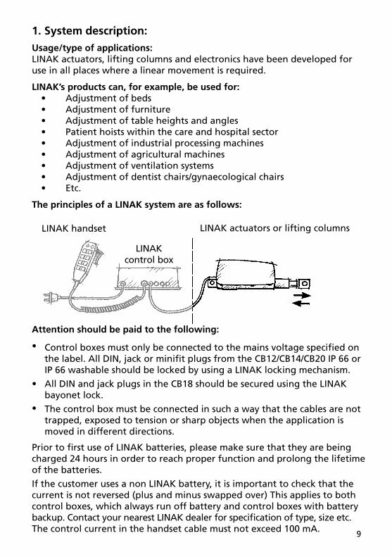
1. System description:Usage/type of applications:LINAK actuators, lifting columns and electronics have been developed for use in all places where a linear movement is required.
LINAK’s products can, for example, be used for: • Adjustment of beds • Adjustment of furniture • Adjustment of table heights and angles • Patient hoists within the care and hospital sector • Adjustment of industrial processing machines • Adjustment of agricultural machines • Adjustment of ventilation systems • Adjustment of dentist chairs/gynaecological chairs • Etc.
The principles of a LINAK system are as follows:
LINAK control box
LINAK handset LINAK actuators or lifting columns
Attention should be paid to the following:
•
•
•
Control boxes must only be connected to the mains voltage specifi ed on the label. All DIN, jack or minifi t plugs from the CB12/CB14/CB20 IP 66 or IP 66 washable should be locked by using a LINAK locking mechanism.
All DIN and jack plugs in the CB18 should be secured using the LINAK bayonet lock.
The control box must be connected in such a way that the cables are not trapped, exposed to tension or sharp objects when the application is moved in different directions.
Prior to fi rst use of LINAK batteries, please make sure that they are being charged 24 hours in order to reach proper function and prolong the lifetime of the batteries.
If the customer uses a non LINAK battery, it is important to check that the current is not reversed (plus and minus swapped over) This applies to both control boxes, which always run off battery and control boxes with battery backup. Contact your nearest LINAK dealer for specifi cation of type, size etc.The control current in the handset cable must not exceed 100 mA.

10
The control box is the heart of the system and connects the various outlying units (actuators, lifting columns, handsets and attendent controls). Control boxes differ widely in complexity. The simplest are only able to convert control signals from the handset into operating voltage for the actuator. The most advanced are microprocessor controlled and have advanced functions such as, parallel running of several actuators and other complex correlations. Most LINAK control boxes provide an Electronic Overload Protection (EOP), designed to protect the actuator (excl. LA12, LA29, LA31, LA34), against overload by disconnecting the current when the actuator is fully extended or retracted. If an LA12, LA29, LA31, LA34 actuator is used, the built-in limit swit ches stop the actuator when fully extended or retracted, and the control box only disconnects when the maximum current is exceeded. When using a CB9 control box it is important to note that not all types of CB9 have electronic overload protection.
The actuator is the unit, which converts the operating voltage from the control box into a linear movement.
The principle of the LINAK actuator’s mode of operation is that a low voltage DC motor (5), via a gear system (12), rotates a threaded spindle, on to which a nut is fitted. As this nut cannot rotate, since the piston rod (2) is restrained, the piston rod will move forwards or backwards, when the threaded spindle rotates.
Fundamental actuator construction
8 7 6 5
11 1213
109 4 3 12
1. Piston rod eye2. Piston rod3. Location of mechanical splines4. Location of brake5. Motor6. Motor with optical switch7. Motor with potentiometer
8. Motor with reed-switch9. Back fixture10. Back fixture with electrical splines11. Quick release mechanism12. Transmission between motor and spindle13. Cable for connection to 12/24/36V DC by means of plug via control box

11
On the basis of motor type, gearing and the threaded spindle’s pitch, the actuator’s thrust and speed are determined.
The handset is the unit to be used when you want the LINAK® system to perform a movement. It determines whether the control box will make the actuator move in or out. There are many variants of LINAK handsets.
The Attendant Control (ACC, ACK, ACL, ACM, ACP) is an accessory used when nursing staff want to restrict the patients adjustment options of a bed. It is often used in conjunction with a handset and disables selected functions on the handset. It can also have control functions with the same function as those on the handset.

12
Warranty and service lifeThe LINAK warranty covers manufacturing defects in the products, starting from the date of manufacture. There is an 36 months’ warranty on the HOMELINE products, 18 months’ for MEDLINE and CARELINE products and 12 months’ for the TECHLINE products. The warranty is limited to the value of the LINAK product.
LINAK’s guarantee is only valid in so far as the products have been used and maintained correctly and has not been tampered with. Furthermore, the products must not be exposed to violent treatment. In the event of this, the warranty will be ineffective / invalid. LINAK’s warranty is only valid if the system is unopened and has been used correctly.
All LINAK products are designed to have an optimum service life as a matter of course, but the expected service life in a specifi c application is very dependent on how the products are used. Therefore, the customer must investigate the service life for the application in question, if necessary in cooperation with LINAK.

13
IP Protection degree:The products can be cleaned as follows according to their IP protection, which is stated on the product label:
IP PROTECTION CLEANING INSTRUCTIONS
IP X0 Clean with a damp cloth.
IP X1 Clean with a damp cloth.
IP X2 Clean with a damp cloth.
IP X3 Clean with a damp cloth.
IP X4 Clean with a damp cloth.
IP X5 Wash with a brush and water, but not water under pressure.
IP X6 X Wash with a brush and water. The water can be under pressure, but the system must not be hosed down directly with a high pressure cleaner. Max. 20oC.
IP X6 W* Clean by the use of water tunnels
X can have a value of between 1 and 6.* The following products can be marked with IP x6, but they are still allowed for wash tunnels : ACP, ACM (mini), ACM (new), BA18, CB12/14/18, DJB, FS2, HB40, LA28, LA32, LA34 stand., LA34 comp..
The materials are resistant to the majority of cleaners and disinfectants used in the hospital and nursing home sector.
Cleaning with a steam cleaner, for example, is not permitted, as it will not be possible to maintain a minimum distance of 300 mm from the electrical parts.
IP 66W products can be washed in wash tunnels that wasches according to the “Maschinelle Dekontamination” provided that the following guidelines are complied with:
• The cleaning and disinfection cycle in the wash tunnel must not last longer than 10 minutes.
• The nozzle pressure in the wash tunnel must not exceed 10 bar.
• The distance between the nozzle and the electrical parts must be at least 300 mm.
• The handset and motor plug must be pushed right in.
• The water temperature must not exceed 85°C.• Cooling with cold water is not permitted.
To avoid degreasing of the piston rod, the actuator should be retracted to minimum stroke before washing.

14
The following directions regarding cleaners and disinfectants must be complied with:• They must not be highly alkaline or acidic (pH value 6-8).
• They must not contain caustic agents.
• Their contents must not be able to change the structure of the surface or adhesion of the plastic.
• They must not break down grease.
The following disinfectants/detergents are recommended:• Neodischer Dekonta, dosage 1-3%, made by CHEMISCHE FABRIK Dr. WEIGERT
• CCOTRADE RW, dosage 0.5%, made by CCOTRADE GmbH.
Warning!The systems must not be sprayed directly with a high pressure cleaner.

15
MaintenanceValid for all LINAK products• The LINAK products must be cleaned at regular intervals to remove dust and dirt and inspected for mechanical damage, wear and breaks.
• The LINAK products are closed units and require no internal maintenance.
• Only type IP 66 is waterproof and type IP 66W tolerates being washed in tunnels.
• The LINAK products must be IP 66 washable when cleaning in wash tunnels. Make sure that the plugs are correctly fi tted with O-rings before washing.
• O-rings: When individual parts are replaced in a LINAK IP 66 or IP 66 wash-able system, the O-rings on all parts, must be replaced at the same time. On control boxes with a replaceable mains fuse, the O-ring in the fuse cover must be replaced every time the cover has been removed. The O-rings must be greased in water free vaseline when replacing them. Make sure that the counterpart - the socket - is clean and undamaged.
Valid for all LINAK actuators and lifting columns• Actuators/lifting columns must be inspected at attachment points, wires, piston rod, cabinet and plug, as well as checking that the actuator/ lifting columns function correctly.
• To ensure that the pregreased inner tube remain lubricated the actuator must only be washed down when the piston rod is fully retracted.
Valid for all LINAK control boxes and handsets• Electronics must be inspected at attachment points, wires, cabinet and plugs.
• Inspect the connections, cables, cabinet and plugs, and check for correct functioning (does not apply to battery versions).
• With the exception of the CS16 and CS18 PCB the control boxes are sealed and maintenance-free.
• Inspect at regular intervals that the ventilation aperture on the external battery is positioned correctly and is intact throughout its length, approx. 20 mm., see fi gure 1.

16
Environmental conditions:
Environment conditions
Operating:
TemperatureRelative humidityAtmospheric pressure
5°C to 40°C20% to 90% @ 30°C – not condensing700 to 1060 hPa
Storage:
TemperatureRelative humidityAtmospheric pressure
-10°C to +50°C20% to 90% @ 30°C – not condensing700 to 1060 hPa
Valid where nothing otherwise is stated under the specifi c products in a later section.
17
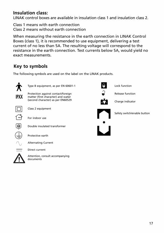
Insulation class:LINAK control boxes are available in insulation class 1 and insulation class 2.
Class 1 means with earth connectionClass 2 means without earth connection
When measuring the resistance in the earth connection in LINAK Control Boxes (class 1), it is recommended to use equipment, delivering a test current of no less than 5A. The resulting voltage will correspond to the resistance in the earth connection. Test currents below 5A, would yield no exact measurements.
Type B equipment, as per EN 60601-1
Protection against contact/foreign matter (first character) and water (second character) as per EN60529
Class 2 equipment
For indoor use
Double insulated transformer
Protective earth
Alternating Current
Direct current
Attention, consult accompanying documents
Key to symbols
Lock function
Release function
Charge indicator
Safety switch/enable button
IPXX
The following symbols are used on the label on the LINAK products.

18
Demko approval
Fimko approval
Australian approval mark
Australian approval mark
Recognized - Component Mark
CanadianRecognized - Component Mark
RecognizedComponent Mark for Canada and the United States
T-Mark
RW-Tüv approval
Tüv.Produkt Service
TÜVRheinland
ETL
C-ETL
LGA
UL Listing Mark
C-UL Listing Mark
C-UL US Listing Mark
UL Listing Mark
M
UL fi le number
UL fi le number
UL fi le number
CSA
PSE-Mark
Product with a thermofuse
For indoor use (House).
Safety isolating transformer.
Electronic scrap
Equipment Kl.2 (Double square)
Patient part of type B (Mand)
Patient part of type BF
Earth protection
Equipment class1.
Earth
CE Mark
C-TICK

19
Mounting:Actuator:Do not use any other screws for the mounting brackets than those recommended by LINAK. If longer screws are used they will come into contact with the inner parts of the actuator. This will result in an irregular operation or even damage the actuator.
During mounting, the actuator must always be:• Fixed, to protect it against torque and bending. See Figure 2.
• Fixed, so that it is restrained, but free to move on its mountings. See Figure 3.
• Fixed in brackets, which can take up the torque reaction. See Figure 3.
• Mounted at right angles, so that the right angle requirement is observed. See Figure 4.
• Mounted with correct bolt dimension.
• Mounted with bolts and nuts made of steel.
• Bolts and nuts must be protected from being able to fall out.
Control boxes:• The mounting screws on the control box must be tightened with a maximum torque of 1 Nm
• The mounting surface to which the control box is attached should have a surface evenness better than ±0.5 mm.
• Systems must not be installed/deinstalled while in operation.
• Control boxes with a wet alarm must be mounted as shown on fi gure 5.
• Nuts and bolts must be made of steel.
• Nuts and bolts must be tightened securely.
The correct bolt size for securing the CB6, CB8, CB12, CB14, CB18 and CB20, is Ø5 mm and the ACP box is M5.

20
Connecting the system:Do not connect the mains cable until all actuators and handsets are connected to the control box.
Start by connecting the handset to the control box. The connection in the control box is marked with “HB”.
Connect the different actuators to the different channels on the control box. Each channel is marked with a number (e.g. “1”, “2”, “3”…….).
Check that all plugs are well connected and fi rm pushed into the connection plug. Due to the fact that LINAK control boxes are designed for a high IP degree a fi rm force can be required.
Connect the mains cable. The actuators can now be operated by pushing a button on the handset. Use only one button at the time. If the control box is equipped with a special software an initializing process might be necessary. This process is described in the software specifi cation.
LINAK control box
LINAK handset LINAK actuator or lifting column
Attention should be paid to the following:
•
•
•
Control boxes must only be connected to the mains voltage specifi ed on the label. All DIN, jack or minifi t plugs from the CB12/CB14/CB20 IP 66 or IP 66 washable should be locked by using a LINAK locking mechanism.All DIN and jack plugs in the CB18 should be secured using the LINAK bayonet lock.The control box must be connected in such a way that the cables are not trapped, exposed to tension or sharp objects when the application is moved in different directions.
Prior to fi rst use of LINAK batteries, please make sure that they are being charged 24 hours in order to reach proper function and prolong the lifetime of the batteries.
If the customer uses a non-LINAK battery, it is important to check that the current is not reversed (plus and minus swapped over) This applies to both control boxes, which always run off battery and control boxes with battery backup. Contact your nearest LINAK dealer for specifi cation of type, size etc. The control current in the handset cable must not exceed 100 mA.

21
Any non-detachable power supply cord with mains plug are considered as the disconnecting device.
All types of actuators may only be connected according to the label, where the voltages 12, 24 or 36 VDC are indicated.
a) Actuators with jack plugs may only be connected to LINAK control boxes
b) Actuators without plugs are connected as shown in Figures 6.1 - 6.12.
For actuators operating without a control box, the mains supply of the actuator must be equipped with an arrangement, which switches off the actuator at end-stop (e.g. LS or LSD limit switch). If there is a risk of overloading the actuator, the mains supply must be equipped with a safety device against overloading (e.g. a CS16 PCB). If this requirement is not observed, the actuator may be damaged.
JUMBO system (special information):The LINAK JUMBO system is specially developed for patient lifts, offering various combinations of actuators and control boxes.
Connecting the system:Mount the mounting bracket (MBJ) to the application. Mount control box and battery (and charger (CHJ2) if equipped).
If it is a JUMBO Home system mount the control box on the application (no mounting bracket is needed).
Connect the handset to the control box. The connection in the control box is marked with “HB”.
Connect the actuators to the control box. Each channel is marked with a number (e.g. “1”, “2”). Channel “1” has always to be used for the High / Low (Lifting) function.
The actuators can now be operated by pushing a button on the handset. Use only one button at the time.
Example of JUMBO patient lift system
1
2
3 4
5
1
2
3
4
5
Handset
Battery
Charger
Control box
Mains plug
+ Actuators
6 7
6 7

22
4
1
2
3
Battery
Charger
Light indicationfor mains connection
Light indicationfor charging
1
2
3
4
1
2
1
2
3
45 6
1) 2)
4
1
2
3
Battery
Emergency stop
Control box
LCD-displayfor battery condition
4
1
2
3
5
Battery
Charger
Control box
Output for handset
+ Output for actuators
6
1) 2) 3)
3)
3
4
Configuration of the JUMBO System
JUMBO Home System
23
2. Information on start-up, de-installation and operation:Before installation, de-installation or troubleshooting:• Stop the actuator/lifting column.
• Switch off the power supply or pull out the mains plug and pull out the plug to the actuator/lifting column.
• Relieve the actuator/lifting column of any loads, which may be released during the work.
Prior to fi rst use of LINAK batteries, please make sure that they are being charged 24 hours in order to reach proper function and prolong the lifetime of the batteries.
Before start-up:• Make sure that the system has been installed as instructed in the User Manual.
• The individual parts (actuator/lifting column/handsets etc.) must be connected before the control box is connected to the mains.
• Make sure that the voltage of the mains to be connected to the product or the system is the one stated on the label.
• Make sure that the actuator/lifting column is connected to a mainselectricity supply/transformer with the correct voltage and which is dimensioned and adapted for the actuator in question.
• The equipment can be freely moved over the actuator/lifting column’s whole working area.
• Check correct function after mounting.
• The actuator/lifting column must not be loaded in excess of the values indicated in the specifi cations on the product label.
• The duty cycle noted on the product label must always be noted. Other-wise there is a risk of damaging the products. Exceeding the duty cycle will result in a dramatic reduction of the life time of the system. Unless specifi ed otherwise on the product label the duty cycle is max. 10% : Max. 2 minutes in use followed by 18 minutes not in use.
• The actuator/lifting column system may only be used in an environmentcorresponding to the system’s IP-rating. LINAK products are marked with the actual IP-rating on the label.
During operation:• Listen for unusual sounds and watch out for uneven running. Stop the actuator/lifting column immediately if anything unusual is observed.
• If the control box makes unusual noises or smells switch off the mains voltage immediately and the external battery, if any.
• Take care that the cables are not damaged.
• Unplug the mains cable on mobile equipment before it is moved.

24
Actuators/lifting columns Symptom Possible cause Action
No motor sound or - The actuator is not connnected - Connect the actuator to movement of to the control box the control boxpiston rod - Blown fuse in the control box - Fuse must be changed - Cable damaged - Send actuator for repair
Excessive electricity - Send actuator for repairConsumption
Motor runs but spindle - Gear wheel or spindle damaged - Send actuator for repairdoes not move
Actuator cannot lift - Clutch is worn - Send actuator for repairfull load - Motor is damaged
Motor sound but no - Send actuator for repairmovement of piston rod
No signal from - Send actuator for repairReed or Hall switch
Motor runs and quick - Declutching arm turns less than - Adjust cablerelease does not approx. 75°function or is noisy
Piston rod will only - Safety nut has operated - Send actuator for repairmove inwards andnot outwards
Motor runs too slowly - Insufficient power supply - Increase power supplyor does not give full - Voltage drop in cable - Thicker cableforce
Troubleshooting

25
Electronics
Symptom Possible cause Action
Power indicator does not - Not connected to mains - Connect to mainslight up - The fuse has blown - Replace fuse, if the system is prepared for external fuse replacement, or send the system for repair
- Defective power cable - On control boxes with exchangeable power cable change the cable. - On control boxes with fi xed cable send it for repair
- Control box defective - Send control box for repair
Power indicator lights up - Actuator plug not pushed - Push actuator plug into controlbut actuator does not run into control box properly box properly
Relays in control box are - Actuator defective - Replace actuatorheard clicking - Control box defective - Replace the control box
Power indicator lights up but - Control box defective - Send control box for repairactuator does not run
No relay noise is heard from - Handset defective - Send handset for repaircontrol boxNot valid for CB20
Control box completely - Battery completely fl at - Charge batterydead on battery and norelay clicking is heard - Battery defective - Replace battery
Actuator does not run on - Actuator plug not properly - Push actuator plug properlybattery, but relay clicking pushed into control box into control boxis heard - Actuator defective - Replace actuator
- Control box defective - Replace control box
Control box okay apart from - Handset defective - Send handset for repairone direc tion on one channel - Control box defective - Send control box for repair

26
3. Information on specifi c actuators :1. LA12 (TECHLINETM)
Thanks to the small size and outstanding performance, the LA12 actuator provides a practical and cost-effective alternative to traditional pneumatic systems and gear motors.
The LA12 is ideal for automating industrial and agricultural machines, feeding, ventilation systems troughs and many other applications requiring short linear movement.
Installation instructionsThe actuators model LA12 must be installed in a fi xed position.
Reed-switch:Reed-switch gives a number of pulses for each rotation of the motor. These pulses are used to calculate the piston rod’s position as well as to control several actuators running in parallel.
Your nearest LINAK dealer can inform the number of pulses per stroke length.
Regarding Reed-switch connection, see Figure 6.4 (LA12R)
If the LA12 actuator is mounted in an application where a mechanical stop prevents the installed end-stop switches in LA12 from being activated, the LA12 actuator must be equipped either with an electrical safety device, a timer or an electronic limit switch. Therefore, please contact your nearest LINAK dealer for technical data.
Built-in end-stop circuitEnd-stop switch is part of the actuator construction. Each time the actuator reaches end-stop position the switch is activated and the current is cut off.
SUPPLEMENTARY FOR LA12 ATEX (Protection class 8)Special conditions for safe use:The permanently attached cable shall be terminated in a non-hazardous area or inside an enclosure that is certifi ed in a type of explosion protection as described in EN 50014 clause 1.2.
The duty cycle of the actuator is limited to 6 minutes ON - 54 minutes OFF.
The actuator model LA12 is to be installed where it is protected against direct sunlight.

27
2. LA22 (MEDLINE® CARELINE® TECHLINETM)
LA22 is an in-line actuator specially designed with a small overall dimension for easy use in industrial, agricultural and rehabilitation products.
Thanks to its small outer dimensions and linear design, LA22 is well suited for applications where installation space is limited, such as on wheelchairs.
3. LA27 (MEDLINE® CARELINE® HOMELINE®)
The LA27 actuator is a powerful actuator designed for applications such as furniture and care beds.
Built-in end-stop circuit (CS27)In the LA27/CS27 the actuator is switched off at the end position. There is no overload protection.
• LA27CS27 has no IP classifi cation and is connected to a HB71 or HB72. The power supply is TR6 or TR7.
It is important that the supply voltage 24 VDC is connected correctly (see Figure 6.7) otherwise the CS-circuit may be destroyed.
Mechanical spline:The splines function so that the actuator can only push, not pull.
During pull in the actuator, the inner tube is lifted off the thread bush, and the actuator can therefore never pull a load, only push.
Functional test of mechanical splines:When the piston rod is at the innermost position, it must be possible to pull it out manually to its full travel length and to press it in again without much resistance and without using the motor. If this is not possible, contact your nearest LINAK dealer.

28
Quick Release:LA27 with QR is designed to be used as a part of the backrest function in a Care/Hospital bed. The QR function allows a patient to be lowered manually to a fl at position very quickly (CPR) in case of an emergency.
Functional test of QR:To test a LA27QR it is necesarry to have the actuator built into an application. The release cable has to be provided and mounted by the customer.The necesarry force on the cable requiered to operate the Quick Release is approx. 20 kg. The necesarry force on the actuator to operate the quick release is approx. 50 kg. Wenn operating the QR, it is recommended that the QR is activated all the way down.
Warning!If the actuator does not work as described above, the risk of injury due to squeezing can arise. The actuator must therefore be sent immediately for service at the nearest, authorised LINAK workshop.
Warning!The actuator must not be used in pull applications when the quick release is activated, as the risk of personal injury can arise.
4. LA28 (MEDLINE® CARELINE® TECHLINETM)
The LA28 is primarily a system actuator. The actuator is very quiet and powerful designed for use in the furniture, rehabilitation and hospital bed line of businesses.
The actuator is also ideal for use in agricultural machinery and for a wide range of industrial applications.
Reed-switch :Reed-switch gives a number of pulses for each rotation of the motor. These pulses are used to calculate the piston rod’s position as well as to control several actuators running in parallel.
Your nearest LINAK dealer can inform the number of pulses per stroke length.
Regarding Reed-switch connection, Figure 6.8 (LA28R)
Built-in end-stop circuit (CS28/CS28S)In the LA28 actuator, with built-in CS28 A-, B- or C-PCB, the actuator is switched off at the end position or when overloaded.

29
LA28 actuator with:• CS28 A is standard IP 51 and is connected to a HB41 handset with a telephone plug.
• CS28 B is standard IP 65 and is connected to a HB41 handset with a DIN plug. CS32 B is also available in IP66.
• CS28 C is standard IP 51 and is connected to an external contact or control. See fi gure 6.7.
Mechanical spline:The splines function so that the actuator can only push, not pull.
During pull in the actuator, the inner tube is lifted off the thread bush, and the actuator can therefore never pull a load, only push.
Functional test of mechanical splines:When the piston rod is at the innermost position, it must be possible to pull it out manually to its full travel length and to press it in again without much resistance and without using the motor. If this is not possible, contact your nearest LINAK dealer.

30
5. LA29 (HOMELINE®)
The LA29 actuator is the latest HOMELINE® actuator. The LA29 is specially made for domestic applications.
The actuator has a very short installation dimension as the distance between the two fi xing points is small when the actuator is retracted and at the same time independent of the stroke length.
Reed-switch:Reed-switch gives a number of pulses for each rotation of the motor. These pulses are used to calculate the piston rod’s position as well as to control several actuators running in parallel.
Your nearest LINAK dealer can inform the number of pulses per stroke length.
Regarding Reed-switch connection, see Figure 6.10.
Built-in end-stop circuitThe end-stop switch is part of the actuator construction. Each time the actuator reaches end-stop position the switch is activated and the current is cut off.

31
6. LA30 (MEDLINE® CARELINE® TECHLINETM)
The LA30 is a powerful actuator yet small enough to fi t most applications.
The actuator can be supplied with options such as built-in potentiometer for servo operation or an extra powerful motor for increased speed and strength (S-motor).
In addition to industrial and agricultural applications, the actuator is also ideal for positioning satellite dishes.
Reed-switch:(Reed-switch gives a number of pulses for each rotation of the motor. These pulses are used to calculate the piston rod’s position as well as to control several actuators running in parallel.
Your nearest LINAK dealer can inform the number of pulses per stroke length.
Regarding Reed-switch connection, see Figure 6.10.
Mechanical spline:The splines function so that the actuator can only push, not pull.
During pull in the actuator, the inner tube is lifted off the thread bush, and the actuator can therefore never pull a load, only push. See Figure 8.
Functional test of mechanical splines:When the piston rod is at the innermost position, it must be possible to pull it out manually to its full travel length and to press it in again without much resistance and without using the motor. If this is not possible, contact your nearest LINAK dealer.
32
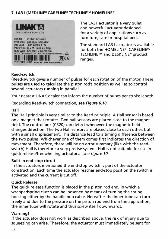
7. LA31 (MEDLINE® CARELINE® TECHLINETM HOMELINE®)
The LA31 actuator is a very quiet and powerful actuator designed for a variety of applications such as furniture, care or hospital beds.
The standard LA31 actuator is available for both the HOMELINE®, CARELINE®,
TECHLINE™ and DESKLINE® product ranges.
Reed-switch:(Reed-switch gives a number of pulses for each rotation of the motor. These pulses are used to calculate the piston rod’s position as well as to control several actuators running in parallel.
Your nearest LINAK dealer can inform the number of pulses per stroke length.
Regarding Reed-switch connection, see Figure 6.10.
HallThe Hall principle is very similar to the Reed principle. A Hall sensor is based on a magnet that rotates. Two hall sensors are placed close to the magnet fi eld. The control box (CB20) can detect whenever the magnetic fi eld changes direction. The two Hall-sensors are placed close to each other, but with a small displacement. This distance lead to a timing difference between the two pulses. Whichever one of them comes fi rst indicates the direction of movement. Therefore, there will be no error summary (like with the reed-switch) Hall is therefore a very precise system. Hall is not suitable for use in quick release/freewhelling actuators. . see fi gure 10
Built-in end-stop circuitIn the actuators mentioned the end-stop switch is part of the actuator construction. Each time the actuator reaches end-stop position the switch is activated and the current is cut off.
Quick ReleaseThe quick release function is placed in the piston rod end, in which a wrappedspring clutch can be loosened by means of turning the spring housing either by the handle or a cable. Hereafter the inner tube can turn freely and due to the pressure on the piston rod end from the application, the inner tube will rotate and thus screw itself downwards.
Warning!If the actuator does not work as described above, the risk of injury due to squeezing can arise. Therefore, the actuator must immediately be sent for

33
service at the nearest, authorised LINAK workshop.
Warning!The actuator must not be used in pull applications when the quick release is activated, as the risk of personal injury can arise.
Internal Quick Release:LA31 with QR is designed to be used as a part of the back rest function in a Care/Hospital bed. The QR function allowes a patient to be lowered manually to a fl at position very quickly (CPR) in case of an emergency.
New version of quick release. The new version of the Quick Release is integrated in the clutch of LA31.
It operates by way of a release cable that is pulled. Hereafter the clutch is declutched and the spindle can turn freely. Due to the pressure on the piston rod end from the application, the spindle will rotate thus moving the actuator inwards.
Due to this new version the LA31 actuator can keep its standard installation dimension and has a protection class up to IP 66 washable.
The quick release is e.g. used for emergency lowering of the headrest part of a bed
Functional test of QR:To test a LA31QR it is necesarry to have the actuator built into an application. The release cable has to be provided and mounted by the customer. The necesarry force on the cable requiered to operate the Quick release is approx. 5 kg. The necesarry force on the actuator to operate the quick release is approx. 50 kg. Wenn operating the QR, it is recommended that the QR is activated all the way down.
Mechanical spline:The splines function so that the actuator can only push, not pull.
During pull in the actuator, the inner tube is lifted off the thread bush, and the actuator can therefore never pull a load, only push. See fi gure 8.
Functional test of mechanical splines:When the piston rod is at the innermost position, it must be possible to pull it out manually to its full travel length and to press it in again without much resistance and without using the motor. If this is not possible, contact your nearest LINAK dealer.

34
8. LA32 (MEDLINE® TECHLINETM)
The LA32 actuator is a powerful actuator that can be supplied with a ball screw spindle to give outstanding performance. The ideal choice for a wide range of applications including adjustment of hospital beds.
The LA32 actuator has many special options including a safety nut, splines, quick release (F) and an optional protection up to IP 66 standard.
Reed-switch:(Reed-switch gives a number of pulses for each rotation of the motor. These pulses are used to calculate the piston rod’s position as well as to control several actuators running in parallel.
Your nearest LINAK dealer can inform the number of pulses per stroke length.
Regarding Reed-switch connection, see Figure 6.10.
Freewheeling of piston rodAll LA32 actuators with freewheeling as well as with quick release have the designation W on the label.
The function causes the following:• The piston rod can be pulled out with a thrust of approx. 300 N and it remains in the new position without declutching.
• The actuator cannot pull, but only push.
Functional test:It must be possible to pull the piston rod out with a thrust of approx. 300 N and it must remain in the new position without releasing. If this is not possible, contact your nearest LINAK dealer.
Built-in end-stop circuit (CS32)In the LA32 actuators, with built-in CS32 A-, B- or C-PCB, the actuator is switched off at the end position or when overloaded.
LA32 actuator with:• CS32 A is standard IP 51 and is connected to a HB41 handset with a telephone plug.
• CS32 B is standard IP 65 and is connected to a HB41 handset with a DIN plug. CS32 B is also available in IP66.
• CS32 C is standard IP 51 and is connected to an external contact or control. See Figure 6.7.

35
Mechanical spline:The splines function so that the actuator can only push, not pull.
During pull in the actuator, the inner tube is lifted off the thread bush, and the actuator can therefore never pull a load, only push. See fi gure 8.
Functional test of mechanical splines:When the piston rod is at the innermost position, it must be possible to pull it out manually to its full travel length and to press it in again without much resistance and without using the motor. If this is not possible, contact your nearest LINAK dealer.
Electrical splines:In the rear fi xture on the actuator, a microswitch is fi tted, which turns off the motor, if the actuator is exposed to pull forces.
Functional test of electrical splinesWhen the actuator is correctly fi xed/mounted, the inward movement of the piston must stop, when the actuator is pulled or the movement is blocked, so that the back fi xture is not put under undue stress/tension. For mounting, see Figure 7.
Quick releaseWhen the quick release arm, see Figure 9, is turned counter clockwise approx. 75° and fi xed here, the piston rod is released and can now be pressed in to its innermost position or pulled out to its outermost position. When the quick release arm is released, the arm turns back and the actuator functions normally again. The cable must not be tight.
Warning!If the actuator does not work as described above, the risk of injury due to squeezing can arise. Therefore the actuator must be sent immediately for service at the nearest, authorised LINAK workshop.
Warning!The actuator must not be used in pull applications when the quick release is activated, as the risk of personal injury can arise.

36
9. LA34 (MEDLINE® TECHLINETM)
Reed-switch:Reed-switch gives a number of pulses for each rotation of the motor. These pulses are used to calculate the piston rod’s position as well as to control several actuators running in parallel.
Your nearest LINAK dealer can inform the number of pulses per stroke length.
Regarding Reed-switch connection, see Figure 6.10.
If the LA34 actuator is used in connection with a non-LINAK power supply the system must be equipped with current trip cut-off.
Adjustment of the installation dimension N
As standard the installation dimension on the LA34 actuator can be manually adjusted by +4/-0 mm (not possible for mechanical splines). The adjustment of the installation dimension must only be made without use of tools only, or hand). It is not allowed to use tools to adjust the installation dimension of the LA34 actuator as there is a risk that the inner tube may be unscrewed.
HallThe Hall principle is very similar to the Reed principle. It is a control box, which based on Hall signals, can decide whether the actuator runs out or in. Hall, however, can detect whether the actuator runs in or out. The number of pulses is like Reed. Hall and Reed are placed opposite the potentiometer on the actuator’s worm wheel. Therefore, it is not suitable for use in quick release /free wheelingactuators. see fi gure 10.
PotentiometerThe potentiometer function is mechanically attached to the spindle and registers the number of spindle revolutions. The signal from the potentiometer is measured in Ohm, where the lowest value is measured when the actuator has been run into inward switch stop. The potentiometer is a 10-turn and therefore it is dependent on the stroke length/spindle pitch. see fi gure 6.5
The LA34 actuator is a technological state-of-the-art actuator that, due to its innovative construction can push up to 10,000 N at a speed of 5 mm/sec. and with a power consumption of approx. 7 Amp.
Its compact design, the outstanding performance and a wide range of safety options makes LA34 the right choice for a variety of medical and industrial applications.

37
Mechanical spline:The splines function so that the actuator can only push, not pull.
During pull in the actuator, the inner tube is lifted off the thread bush, and the actuator can therefore never pull a load, only push. See Figure 8.
Functional test of mechanical splines:When the piston rod is at the innermost position, it must be possible to pull it out manually to its full travel length and to press it in again without much resistance and without using the motor. If this is not possible, contact your nearest LINAK dealer.
Electrical splines:In the rear fi xture on the actuator, a microswitch is fi tted, which turns off the motor, if the actuator is exposed to pull forces.
Functional test of electrical splinesIt is important that the actuator is correctly fi xed with regard to the section on page 11. For mounting, see Figure 7.
When the actuator is correctly fi xed/mounted, the inward movement of the piston must stop, when the actuator is pulled or the movement is blocked, so that the back fi xture is not put under undue stress/tension.
Quick releaseLA34 (34xxxF/H) is equipped with a function which permits operation of the actuator should the power source fail. Condition for functioning: the actuator must be loaded in push direction (LA34xxxF) or pull direction (LA34xxxsH).
Warning!If the actuator does not work as described above, the risk of injury due to squeezing can arise. Therefore the actuator must be sent immediately for service at the nearest, authorised LINAK workshop.
Warning!The actuator must not be used in pull applications when the quick release is activated, as the risk of personal injury can arise.
Activation of quick releasePull the release handle in the direction of the piston rod eye (outwards), the harder you pull the button the quicker the actuator runs down. When releasing the button the emergency lowering stops immediately. The emergency lowering is activated as long as the load on the actuator is above 100-150 kg. The actuator is ready for normal use when the emergency lowering is fi nished.
Safety device regarding functional failure of the nut (Safety nut):LA34 has a built-in safety nut in push as standard and is available with a safety nut in pull as an option. Actuators with safety nut in push can only function when used in push applications. The safety nut comes into

38
operation should the main nut fail. Afterwards it is only possible to drive the actuator into the innermost position. Safety nut in pull is for pull applications and works the opposite way as described above. Thereafter the actuator will not function any more and must be sent for service.
Built-in end-stop circuitIn the actuators mentioned the end-stop switch is part of the actuator construction. Each time the actuator reaches end-stop position the switch is activated and the current is cut off.
10. RA40 (MEDLINE® CARELINE® HOMELINE®)
The RA40 Rotary actuator is a compact unit where the fast rotation of the electric motor is converted into a slow turning movement of a lever with a high torque.
The Rotary concept offers new possibilities especially for care bed applications due to the optimum freedom of design.

39
4. Information on specifi c columns :
2. BL3 (MEDLINE® CARELINE®)
The BL3 lifting column is the ideal choice for vertical lift of beds where design, easy cleaning and ergonomics are important factors.
The BL3 is a 3-part telescopic column with a special slide system especially developed to fulfi l the European standard EN 1970 in a care bed that demands an adjustment range from 400 mm up to 800 mm.
The BB3 3-part telescopic actuator is the ideal choice for vertical lift of beds where design and easy integration in the customer’s guidance ensures optimum freedom of design.
The BB3 is a 3-part telescopic actuator designed to meet EN 1970 for care beds, which demands an adjustment range from 350 mm up to 750 mm.
1. BB3 (MEDLINE® CARELINE®)
Reed-switch:Reed-switch gives a number of pulses for each rotation of the motor. These pulses are used to calculate the piston rod’s position as well as to control several actuators running in parallel.
Your nearest LINAK dealer can inform you of the number of pulses per stroke length.
Regarding reed-switch connection, see Figure 6.10.
• The columns must be securely mounted before operation, no rotation must be possible
• The motor housing must be mounted uppermost

40
3. BL4 (MEDLINE® CARELINE®)
The BL4 is a 4-part lifting column specially designed for hospital and care beds; the BL4 can of course be used for other applications where a compact lifting column with a long stroke length is needed.
The lifting column is based on the BB3 actuator, which is practically noiseless. The specifi cations comply with the demands to the lifting functions in beds as to load, speed and stroke length.
Reed-switch:Reed-switch gives a number of pulses for each rotation of the motor. These pulses are used to calculate the piston rod’s position as well as to control several actuators running in parallel.
Your nearest LINAK dealer can inform the number of pulses per stroke length.
Regarding Reed-switch connection, see Figure 6.10.
• There are mounting holes in the endplates and motor housing
• The columns must be securely mounted before operation, no rotation must be possible.
• The motor housing must be mounted uppermost
• The mounting bracket tension must be adjusted correctly

41
5. LP2 (MEDLINE® CARELINE® TECHLINETM)
The LP2 range of vertical lifting columns is ideal where vertical positioning of substantial loads is required.
The design allows the LP2 range to be built in a complete motion control system simply by adding a suitable LINAK control box and handset.
Advanced design and high quality construction allows the column to be operated either as single or parallel with up to a maximum of four units and/or with a memory function.
The LP2 lifting column is the ideal choice for duties such as height adjustment on computer workstations, work benches or a wide selection of other duties.
• There are mounting holes in the end plates.
• The largest profi le must be mounted uppermost
4. LC2 (MEDLINE® CARELINE® TECHLINETM)
The LC2 column is an update of the LP2 program. It has an improved “twisting” stability and end-stop switches as standard.
The column is designed to be used in a vertical position and only for lifting purposes. It is not possible to use the column in any kind of “pull” application.
Depending on the application, the LC2 can be operated either as a single column or several columns in a parallel system by choosing a control box with microprocessor.
It is designed to provide vertical lifting (push only) where simultaneous bending and torsion moments may occur.

42
6. LP3 (MEDLINE® CARELINE® TECHLINETM)
The LP3 is developed for vertical lifts and can resist a bending moment by virtue of the effective telescopic system.
The lifting column is designed for applications where a small installation dimension is requested without compromising the lifting capacity.
The LP3 is characterised by having a lower installation dimension proportional to the stroke length compared to the LP2. The LP3 can also attain a higher speed than the LP2.
The telescopic column is compatible with LINAK’s control boxes and can run individually; as 2 x LP3 parallel and/or with memory.
The LP3 is the perfect choice for height adjustment on dental, gynaecologist and wheelchairs as well as for operating, offi ce and working benches etc.
The column can only be loaded with the maximum bending moment over the fi rst 80 % of the stroke. The maximum bending moment will be reduced to 50%.
The column must be mounted with the largest profi le uppermost!
• There are mounting holes in the end plates.
• The largest profi le must be mounted uppermost

43
5. Information on specifi c controls boxes:Please be aware if the control box is not visible after mounting, all information regarding limitation of use shall be marked on the end product.
Output voltageOn control boxes connected to the mains the voltage at the actuator outputs is dependent on load, and the no-load voltage can reach 50 V. Control boxes connected to a battery can reach a voltage of 30 V during charging and no load.
For all control boxes with batteryPrior to fi rst use of LINAK batteries, please make sure that they are being charged 24 hours in order to reach proper function and prolong the lifetime of the batteries.
Warning!Please observe the following maintenance, replacement and disposal requirements to ensure a safe and reliable operation.
Maintenance of batteriesThe batteries are to be replaced after 4 years at the latest. Perhaps earlier, dependent on the pattern of use. Frequent and high-powered discharges reduce the battery life. For optimum lifetime the product must be connected to the mains voltage as often as possible. The batteries must be charged at least every 3rd month - otherwise they will be damaged in due to self-discharge. It is recommended to test the battery function at least once every year.
Replacement of batteriesThe batteries must only be replaced by the following mechanical and electrical compatible types: Kobe 1.2-6 (6V, 1.2 Ah) Yuasa 1.2-6 (6V, 1.2 Ah) PBQ 1.2-12 (12V, 1.2 Ah) or 1.3-12 (12V, 1.3 Ah) Kobe 1.2-12 (12V, 1.2 Ah) PBQ 2,9-12 (12V, 2.9 Ah) Rocket 2.9-12 (12V, 2.9 Ah)The batteries must be new or maintained by means of charging at least every 3rd month. The batteries, which make a set, must be supplied with identical production codes. Mismatching of production codes may lead to severely reduced life time expectancy.
Interpretation of the production codes are as follows:Kobe: XX (day) XX (month) X (year) X (production line number)Yuasa: X (year) XX (month) XX (day) XX (serial number)PBQ made in Korea: XX (not relevant) X (year) X (month) XX (day) X (not relevant)

44
PBQ made in China: X (year) X (month) XX (day)Example: “DA10” (04-01-10)
Before mounting ensure that the battery set is correctly connected, compare with the drawing in the battery room, and check that no connectors are loose.
Warning!From the factory the battery room is hermatically separated from the electronics room. When replacing the batteries this separation must not be damaged or modifi ed as this may allow penetration of battery gas into the electronics room with risk of explosion.
When replacing batteries in waterproof products (IP 65 and IP 66) precautions must be taken that the sealing material (silicone ring or joint fi ller) is not damaged and that it is correctly placed in the groove. Hereafter the screws in the cover are to be fastened with appox. 1 Nm. If the seal is damaged it must be replaced by a new silicone string (LINAK article no. 0008004 for a roll of 100 metres).
DisposalThe batteries, which are lead-acid batteries, can be returned to LINAK or disposed in the same way as car batteries.
Warning!The battery room is supplied with ventilation that ensures correct and necessary airing of the battery room. This airing must not be blocked or covered as a positive pressure may occur with risk of explosion.
If the product has been exposed to mechanical overload (lost on the fl oor, collision/squeezing in the application or a powerful stroke) the product must be sent to an authorised workshop for control of the hermetic separation between the battery and electronics rooms.

45
The CB8-A is a battery powered control box operating up to 3 actuators individually. One of these channels can be used either as an emergency stop or for battery charging.
Simple design and high quality construction make the CB8-A an ideal control box choice for mains-free operation of beds, chairs, tables and many other mobile applications.
2. CB8-A (CARELINE® TECHLINETM)
1. CB6 (HOMELINE®)
The CB6 control box has been specially developed for use together with LA27 actuator in the care and rehab industry.
The control box is designed to be mounted on the actuator LA27 as with the CB9 and LA31 system.
The CB6 control box has a LED power ON indicator, detachable mains cable and strain relief for all cables.
The control box CB6 communicates with the LA27 actuator by means of the built-in end stop signal switches in the actuator. Due to the signal switches the power to the motor will be cut off in the control box and not in the actuator.
This ensures that it is only possible to run in the opposite direction once the actuator has reached the end position.

46
4. CB9 (MEDLINE® CARELINE® HOMELINE®)
The CB9 has been developed for use in the Care & Rehab industry. CB9 and LA31 can be fully integrated which saves mounting and wiring or be installed separately.
The CARELINE® CB9 series is available as either analogue (Ax) or µ-processor based (Px) types.
CB9PF with mains cut-offIn standby mode the CB9PF with mains cut-off will typically switch off the power supply to the transformer for 3-4 hours, following which it will switch on the mains supply for approx. 3 sec. It will then be switched off again for 3-4 hours. If the control box has an internal/external battery, the power supply to the transformer will not be switched off until the battery is fully charged.
3. CB8-T (TECHLINETM)
The CB8-T is developed for use with LINAK A/S’ actuators and handsets. The control box can operate up to 2 actuators individually.
The simple compact design combined with high quality makes the control box ideal for use with beds, chairs, tables and many other applications.
47
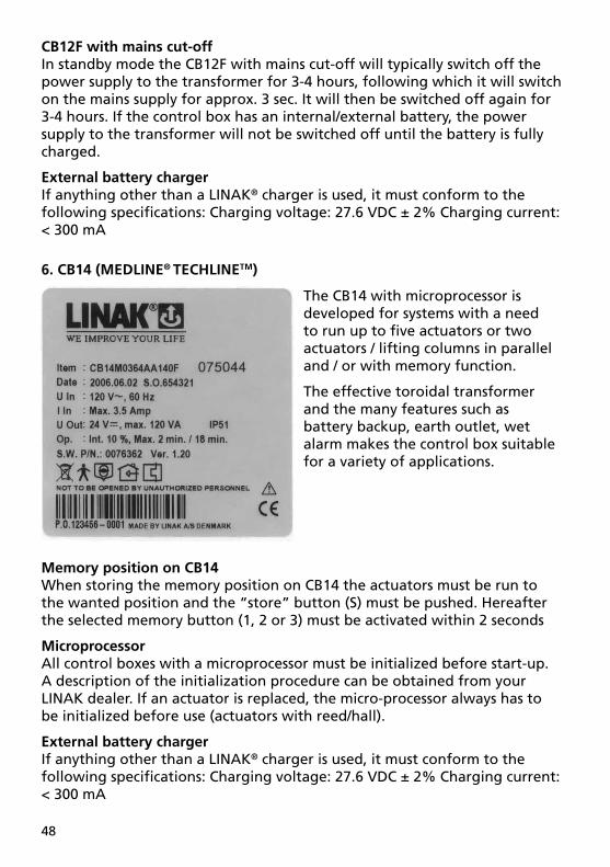
5. CB12 (MEDLINE®)
The CB12 product range features three standard versions, which are ideal for a vast number of medical and industrial applications.
In general the CB12 is a transformer operated control unit, which can control up to 4 actuators. The control box features a range of built-in safety devices, increased current cut-off, EAS (Electronic Arc Suppression) and other options such as battery back-up, earth outlet, wet alarm etc.
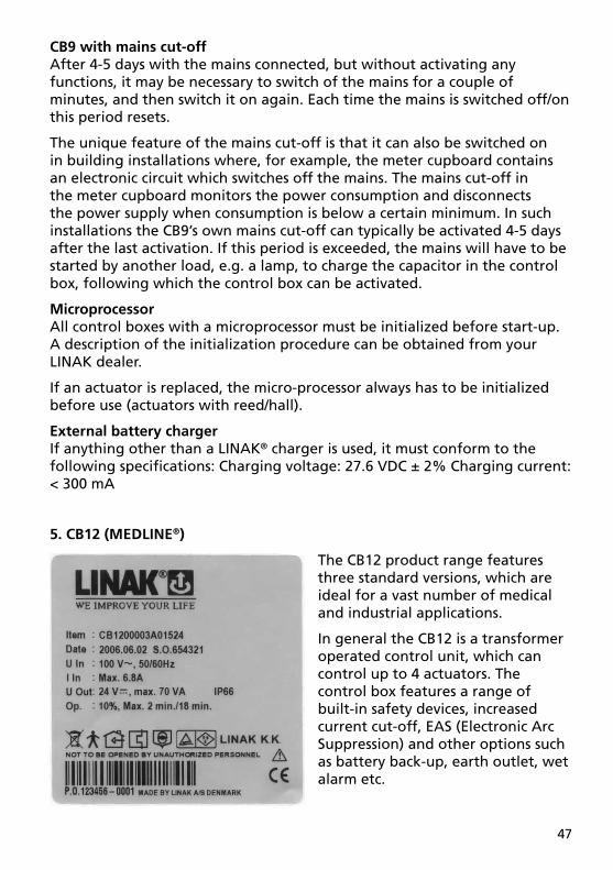
CB9 with mains cut-offAfter 4-5 days with the mains connected, but without activating any functions, it may be necessary to switch of the mains for a couple of minutes, and then switch it on again. Each time the mains is switched off/on this period resets.
The unique feature of the mains cut-off is that it can also be switched on in building installations where, for example, the meter cupboard contains an electronic circuit which switches off the mains. The mains cut-off in the meter cupboard monitors the power consumption and disconnects the power supply when consumption is below a certain minimum. In such installations the CB9’s own mains cut-off can typically be activated 4-5 days after the last activation. If this period is exceeded, the mains will have to be started by another load, e.g. a lamp, to charge the capacitor in the control box, following which the control box can be activated.
MicroprocessorAll control boxes with a microprocessor must be initialized before start-up. A description of the initialization procedure can be obtained from your LINAK dealer.
If an actuator is replaced, the micro-processor always has to be initialized before use (actuators with reed/hall).
External battery chargerIf anything other than a LINAK® charger is used, it must conform to the following specifi cations: Charging voltage: 27.6 VDC ± 2% Charging current: < 300 mA
48
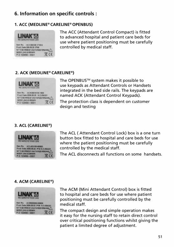
6. CB14 (MEDLINE® TECHLINETM)
The CB14 with microprocessor is developed for systems with a need to run up to fi ve actuators or two actuators / lifting columns in parallel and / or with memory function.
The effective toroidal transformer and the many features such as battery backup, earth outlet, wet alarm makes the control box suitable for a variety of applications.
Memory position on CB14When storing the memory position on CB14 the actuators must be run to the wanted position and the “store” button (S) must be pushed. Hereafter the selected memory button (1, 2 or 3) must be activated within 2 seconds
MicroprocessorAll control boxes with a microprocessor must be initialized before start-up. A description of the initialization procedure can be obtained from your LINAK dealer. If an actuator is replaced, the micro-processor always has to be initialized before use (actuators with reed/hall).
External battery chargerIf anything other than a LINAK® charger is used, it must conform to the following specifi cations: Charging voltage: 27.6 VDC ± 2% Charging current: < 300 mA
CB12F with mains cut-offIn standby mode the CB12F with mains cut-off will typically switch off the power supply to the transformer for 3-4 hours, following which it will switch on the mains supply for approx. 3 sec. It will then be switched off again for 3-4 hours. If the control box has an internal/external battery, the power supply to the transformer will not be switched off until the battery is fully charged.
External battery chargerIf anything other than a LINAK® charger is used, it must conform to the following specifi cations: Charging voltage: 27.6 VDC ± 2% Charging current: < 300 mA

49
Memory position on CB18When storing the memory position on CB18 the actuators must be run to the wanted position and the “store” button (S) must be pushed. Hereafter the selected memory button (1, 2 or 3) must be activated within 2 seconds.
CB18 with wet alarmCB18 with wet alarm must be installed horizontally to ensure correct function of the wet alarm.
MicroprocessorAll control boxes with a microprocessor must be initialized before start-up. A description of the initialization procedure can be obtained from your LINAK dealer. If an actuator is replaced, the microprocessor always has to be initialized before use (actuators with reed/hall).
External battery chargerIf anything other than a LINAK® charger is used, it must conform to the following specifi cations: Charging voltage: 27.6 VDC ±2% Charging current: < 300 mA
7. CB18 (MEDLINE® CARELINE® TECHLINETM)
The CB18 is developed for system solutions, where there is a request for running 2 or more actuators/lifting columns in parallel and/or with memory function.
The CB18 can control up to 6 actuators.
The CB18 offers protection up to IP 66 and is fi tted with a toroidal transformer giving low electromagnetic emission and low power consumption.

50
The CB20 is the platform for the future with a unique safety concept, logging of service data and it is possible to connect a variety of accessories to the control box.
The CB20 consists of 3 modules :
CP20 = Control Power, CU20 = Control Unit and BA20 = Battery.
To ensure the battery pack BA20 has max. effi ciency the following must be complied with:
• The battery pack BA20 must be connected
• Mains voltage must be connected min. 12 hours before use.
MicroprocessorAll control boxes with a microprocessor must be initialized before start-up. A description of the initialization procedure can be obtained from your LINAK dealer. If an actuator is replaced, the microprocessor always has to be initialized before use (actuators with reed/hall).
8. CB20 (MEDLINE®)
9. CBR1 (MEDLINE® CARELINE® HOMELINE®)
The CBR1 has been developed for use together with the Rotary actuator RA40. CBR1 can be installed in the same profi le as the Rotary actuator RA40 thus saving mounting and wiring.
External battery chargerIf anything other than a LINAK® charger is used, it must conform to the following specifi cations: Charging voltage: 27.6 VDC ± 2% Charging current: < 300 mA
51
The ACL ( Attendant Control Lock) box is a one turn button box fi tted to hospital and care beds for use where the patient positioning must be carefully controlled by the medical staff.
The ACL disconnects all functions on some handsets.
3. ACL (CARELINE®)
The ACC (Attendant Control Compact) is fi tted to advanced hospital and patient care beds for use where patient positioning must be carefully controlled by medical staff.
1. ACC (MEDLINE® CARELINE® OPENBUS)
The OPENBUSTM system makes it possible to use keypads as Attendant Controls or Handsets integrated in the bed side rails. The keypads are named ACK (Attendant Control Keypads).
The protection class is dependent on customer design and testing
2. ACK (MEDLINE® CARELINE®)
6. Information on specifi c controls :
The ACM (Mini Attendant Control) box is fi tted to hospital and care beds for use where patient positioning must be carefully controlled by the medical staff.
The compact design and simple operation makes it easy for the nursing staff to retain direct control over critical positioning functions whilst giving the patient a limited degree of adjustment.
4. ACM (CARELINE®)

52
5. ACP (CARELINE®)
The ACP (Attendant Control Panel) controller is fi tted to advanced hospital and patient care beds for use where patient positioning must be carefully controlled by medical staff.
The ACP allows nursing staff to retain direct control over critical positioning functions while giving the patient a limited degree of adjustment.
6. FS (MEDLINE® CARELINE®)
The Foot Switch is a modular system, developed for use together with some of LINAK control boxes. The LINAK Foot Switch is designed for control of physiotherapeutic beds, hospital beds, dentist chairs, gynaecologist chairs, computer workstations and working desks etc. It can also be used as a “stand alone” item for industrial applications.
FootswitchConsist of: FS (a pedal unit) and FSE (electronics unit) which can activate one or more actuators. The module system can max. consist of two pedal units, a FSR (right pedal), a FSL (left pedal) and one electronics box.

53
10. HB60 (MEDLINE® CARELINE® HOMELINE®)
9. HB50 (MEDLINE® CARELINE® TECHLINETM)
8. HB40 (MEDLINE® CARELINE® TECHLINETM HOMELINE®)
The HB40 series handsets are designed for use with most of LINAK control boxes. These sturdy compact units are ergonomically designed and ideal for a vast range of applications from patient care beds and offi ce furniture to industrial and agricultural duties.
The HB50 is primarily designed for the LINAK JUMBO system and most of LINAK control boxes with memory functions. The HB50 gives the user access to a range of memory functions, allowing present positions to be stored. For use in a wide variety of hospital, patient care and industrial applications.
The HB60 series is exclusively designed to be used together with the LINAK HOMELINE® system: LA31/LA29/LA28C/CB7 or CB9 with or without memory.
7. FS2 (MEDLINE® CARELINE®)
The FS2 Foot Switch is developed for use together with some of LINAK control boxes and especially designed for mounting on a support plate.
The Foot Switch is available in a single and a double version.
The double version can be used on a bed where one Foot Switch will be mounted on each side of the bed frame, thus enabling operation from both sides.

54
13. LS (TECHLINETM)
12. HL70 (MEDLINE® CARELINE®)
The HL70 is a handset with integrated locking function, where a selective locking of the different functions is available by use of a special key. The HL70 is an alternative to the HB70 combined with an attendant Control Panel (ACM, ACL, etc.).
11. HB70 (MEDLINE® CARELINE® TECHLINETM)
LINAK offers the HB70 with protection class IP 66 as standard and a range of options such as control of up to 5 actuators, memory and simultaneous drive. The HB70 is designed to operate with most LINAK control boxes.
14. LSD (TECHLINETM)
The LSD type controls the stroke length of the actuator between two fi xed end positions by cutting off the current to the motor.
There are two types of LINAK limit switches, for actuators type LA22, LA30, LA30S , LS and LSD.
The LS type gives a signal in two fi xed end positions, but requires a control unit to stop the actuator when the microswitches are activated.

55
7. Information on specifi c JUMBO :
1. BAJ1 (MEDLINE® CARELINE®)
These battery packs have been specially developed for use with the JUMBO system.
The battery packs are easy to exchange through an integrated snap system.
The battery packs are easily mounted on the JUMBO mounting brackets.
A customised front cover is possible.
The BAJ1 has to be charged with a JUMBO charger CHJ2 or a JUMBO control box CBJ1 or CBJ2 with integrated charger.
The BAJ1 is ventilated through a breather hole on the backside of the housing.
2
2. BAJ2 (MEDLINE® CARELINE®)
These battery packs have been specially developed for use with the JUMBO system.
The battery packs are easy to exchange through an integrated snap system.
The battery packs are easily mounted on the JUMBO mounting brackets.
A customised front cover is possible.
The BAJ2 can be charged as the BAJ1, but can also be charged through an integrated DC-plug for use with charger CH08.
The BAJ2 is ventilated through a breather hole on the backside of the housing.

56
The control boxes CBJ1 and CBJ2 are part of the JUMBO system. JUMBO is a modular system combining an actuator, a control box (CBJ1/CBJ2), a battery (BAJ1/BAJ2) and a charger (CHJ2) in a fl exible solution, specially developed for patient lifts.
The complete system is medically approved and contains a series of features, which meet the patients need for a safe and comfortable lift, e.g. CBJ1 and CBJ2 are equipped with a soft-start/stop function, emergency lowering function etc.
3. CBJ1/CBJ2 (MEDLINE® CARELINE®)
4. CBJH (MEDLINE® CARELINE®)
The CBJ-HOME is a specially developed solution for patient lifts. The complete system consists of a control box and a battery enclosed in a single elegant module. The system will be medically approved and contains a series of features ensuring a safe comfortable lift, e.g. the CBJ-HOME is equipped with a soft-start function, emergency lowering, emergency stop etc.
The CBJH-batteries are ventilated through a number of grill units on the backside of the housing.

57
6. CH08 (MEDLINE®)
For charging of the batteries in the control box CB08-A, directly connected to the control box or via the handset HB40A
For charging of the batteries in battery box BAJ2 (JUMBO system) and CBJH.
LINAK’s product range covers several chargers. The CH08 can be used for the CBJH and CB8-A.
7. CHJ2 (MEDLINE® CARELINE®)
The charger CHJ2 has been specially designed for use as a wall-charger for the JUMBO system.
The CHJ2 charger is a Switch Mode Power Supply (SMPS) version, which makes charging of the batteries more effi cient.
The charging time for a BAJ1 or a BAJ2 battery pack is approx. 4 hours.
Mains voltage from 100 V AC – 240 V AC (50/60 Hz) is possible on same charger.
8. MBJ1/2/3 (MEDLINE® CARELINE®)
Depending on of what your JUMBO system consists you need to use one of the following three mounting brackets. IP protection is only valid when the JUMBO system is mounted vertically.
5. CH01 (MEDLINE® CARELINE®)
For charging the batteries of CB08-XA and all JUMBO control boxes, directly connected to the control box or via the handset HB40A.
For charging of the batteries in battery box BAJ2 (JUMBO system) and CBJH.

58
8. Information on specifi c accessories :If the actuator is to be equipped with accessories, these must be specifi ed when ordering the actuator from LINAK. There are the following possibilities:
1) TR6/TR7 External transformerIf the TR6 or TR7 fi xed cable connection becomes damaged the transformer must be replaced.
1. BA18 (MEDLINE® CARELINE®)
Compatible with CB9, CB18-AT-version, CB12 BT version and CB14 BT version.
The BA18 is exchangeable without opening the CB (BA18 is a separate box).
Ventilation of external batteries, BA18 - see Figure 1
Check at regular intervals that the ventilation stub is undamaged and intact. The construction of the ventilation stub permits battery gasses to get out, but it does not permit penetration of water.
2. CS16 (TECHLINETM)
The CS16 electronic limit switch is connected between the LINAK® actuator and a non-LINAK power supply, where it cuts out the current to the actuator in end position of if an obstacle is encountered. The PCB contains a variable current limit setting and is available in different versions, depending on which actuator it is to be used with.
The CS16 should be connected between the linear actuator and the power supply, where it will switch off the power when the actuator reaches end position or if the actuator is overloaded.
As the CS16 are open PCB’s, they have to be installed in an encapsulation to prevent damage. (LINAK® offers one type of encapsulation for CS16)
Adjustment of CS16The CS16 has a rotary potentiometer for adjusting the value of the cut-off current. To obtain the correct cut-off current, connect the CS16 and turn the potentiometer as far as it will go/anticlock wise to set the maximum cut-off current.

59
3. CS18 (MEDLINE® CARELINE®)
The CS18 print is designed for use in connection with dental-chair applications.
The CS18 print is specially developed to be combined with actuators that have a built-in end-stop print such as LA29, LA31and LA34.
The print is microprocessor based and can handle actuators with potentiometer, reed, hall sensor or actuators without feedback. The CS18 is handled according to EN 100015-1 (EUROSTAT).
The CS18 should be connected between the linear actuator and the power supply, where it will switch off the power when the actuator reaches end position or if the actuator is overloaded.
As the CS18 are open PCB’s, they have to be installed in an encapsulation to prevent damage.
Then subject the actuator to the maximum load it will be exposed to in the application. At the same time turn the potentiometer clockwise, reducing the cut-off current, until the actuator stops (not in end position).
Then turn the potentiometer approx. quarter of a turn anti-clockwise and the system is ready for use.
As the CS16 and the CS18 are open PCB’s, they have to be installed in an encapsulation to prevent damage. (LINAK® offers one type of encapsulation) but only for CS16.
The DIN Junction Box is designed for use where there is a need for more than 1 or 2 controls to be connected to a control box.
The DIN Junction Box is constructed for connection of up to 4 controls with 8-pin DIN plugs. Further-more, the box is constructed so that all channels for connetion are placed on the same side of the box.
This gives the box a clean design and makes it easy to mount e.g. in a bed frame.
4. DJB (MEDLINE® CARELINE®)

60
5. IB18
IB18 is an interface box used as communication link between the control box CB18 and PC when confi guration changes of the control box CB18 (standard software) and downloading of our new software are needed.
6. MJB (MEDLINE® CARELINE®)
The MJB (Modular Junction Box) is designed for use together with the CB20 and other OPENBUSTM control boxes.
The MJB makes it possible to connect handsets, attendant controls and accessories with the CB20. The CB20 has 2 modular jack interfaces, but by using the MJB the connection possiblities are greatly increased. One “modular jack” channel is used for connectin to the CB20.
7. SLS (MEDLINE® CARELINE®)
LINAK has designed a switch that can be mounted in connection with the 24V DC actuators: LA12, LA22, LA28, LA28S, LA31, LA32 or LA34 and a control box on e.g. a bed frame.
The Safety Limit Switch (SLS). The SLS Switch is primarily used as a Limit Switch in systems consisting of a control box, LA28/28S and/or LA32.
As an example the SLS can be installed on the actuator cable where it disconnects the actuator in either inward or outward direction when activated. The SLS can also be used as a signal control directly connected to a control box.

61
9. Repair and disposalRepairOnly an authorised LINAK service centre should repair the LINAK actuator systems. Systems to be repaired under warranty must be sent to an authorised LINAK service centre.In order to avoid the risk of malfunction, all actuator repairs must only be carried out by an authorised LINAK Service shop or repairers, as special tools and parts must be used.
If a system is opened by unauthorised personel there is a risk that it may malfunction at a later date.
Spare parts LINAK can supply spindle parts and motor parts as spare parts. Please indicate the designation from the label when ordering spare parts from your nearest authorised LINAK dealer.
Disposal of LINAK’s productsLINAK’s products may be disposed of, possibly by dividing them into different waste groups for recycling or combustion.
We recommend that our product is disassembled as much as possible at the disposal and that you try to recycle it. As an example of main groups within sorting of waste we can mention the following.Metal, plastic, cable scrap, combustible material and collection for recoverable resources.
Some of these main groups can be sub-divided into groups e.g. metal can be divided into steel and aluminum or plastic can be divided into ABS and PP.
As example of sorting we show you below which recycling groups the different components in LINAK’s products should be placed into:

62
By now nearly all our moulded plastic units are provided with an internal code for plastic types and fi bre content, if any.
Product Component Recycling group
Actuator: Spindle and motor Metal scrap Plastic housing Plastic recycling or combustion Cable Cable scrap or combustion
Control box: PC-board Electronic scrap Plastic housing Plastic recycling or combustion Cable Cable scrap or combustion Transformer Metal scrap Batteries Recoverable resources
Control: Plastic housing Plastic recycling or combustion Cable Cable scrap or combustion PC-board Electronic scrap

63
Main groups of disposal:
Product main type
Metal scrap Cable scrap Electronic scrap
Plastic recycling or combustion
Remark
ACC X X X
ACK X X X
ACL X X X
ACM X X X
ACP X X X
BA18
BAJ1 X
BAJ2 X
BB3 X
BL3 X
BL4 X
CB12 X X X
CB14 X X X
CB18 X X X
CB20 X X X X
CB6 X X X
CB8-A X
CB8-T X
CB9 X X X X
CBJ1 X
CBJ2 X
CBJH X
CBR1 X
CH08 X
CHJ2 X
CS16 X X
CS18 X X
DJB X X X
FS X X X X Metalscrap because of FSR
+ FSR
FS2 X X X
HB40 X X X
HB50 X X X
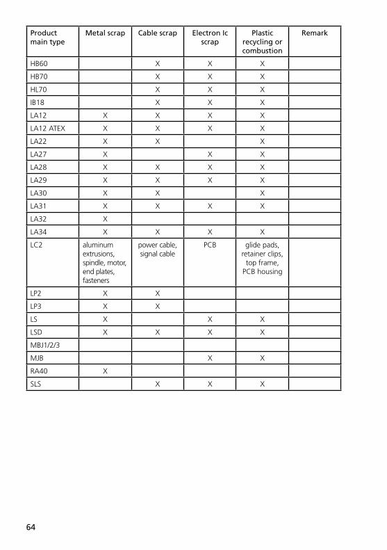
64
Product main type
Metal scrap Cable scrap Electron Ic scrap
Plastic recycling or combustion
Remark
HB60 X X X
HB70 X X X
HL70 X X X
IB18 X X X
LA12 X X X X
LA12 ATEX X X X X
LA22 X X X
LA27 X X X
LA28 X X X X
LA29 X X X X
LA30 X X X
LA31 X X X X
LA32 X
LA34 X X X X
LC2 aluminum extrusions, spindle, motor, end plates, fasteners
power cable, signal cable
PCB glide pads, retainer clips,
top frame, PCB housing
LP2 X X
LP3 X X
LS X X X
LSD X X X X
MBJ1/2/3
MJB X X
RA40 X
SLS X X X

65
Practical information:
ACC
ACK
ACL Cannot be opened since it is welded together. When the cable has been cut off it is disposed of as combustible waste
ACM
ACP
BA18
BAJ1 Screw together
BAJ2 Screw together
BB3 Outer tube (Alu) can be dismounted (screws)
BL3 The actuator (LA31) inside the BL3 can be dismounted (screws)
BL4 Plastic housing and the BB3 inside can be dismounted (screws)
CB12 Screw together
CB14 Screw together
CB18
CB20 Glued and welded together. Cannot be opend
CB6 Screw together
CB8-A Screw together
CB8-T Screw together
CB9 Has to be unscrewed with a screw driver
CBJ1 Screw together
CBJ2 Screw together
CBJH Screw together
CBR1
CH01 Welded together
CH08 Welded together
CHJ2 Screw together
CS16 Screw together, cut off can be adjusted
CS18 No casing/housing
DJB
FS
FS2
HB40
HB50
HB60
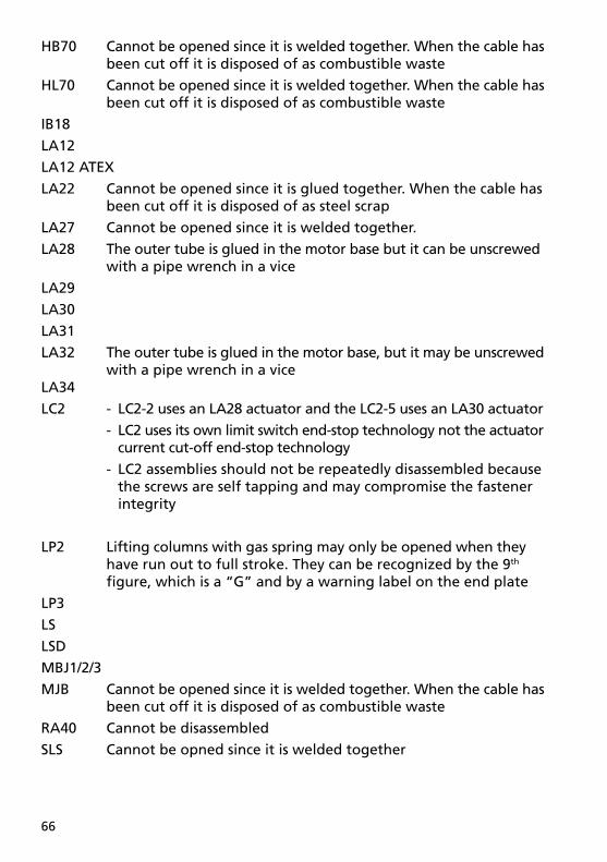
66
HB70 Cannot be opened since it is welded together. When the cable has been cut off it is disposed of as combustible waste
HL70 Cannot be opened since it is welded together. When the cable has been cut off it is disposed of as combustible waste
IB18
LA12
LA12 ATEX
LA22 Cannot be opened since it is glued together. When the cable has been cut off it is disposed of as steel scrap
LA27 Cannot be opened since it is welded together.
LA28 The outer tube is glued in the motor base but it can be unscrewed with a pipe wrench in a vice
LA29
LA30
LA31
LA32 The outer tube is glued in the motor base, but it may be unscrewed with a pipe wrench in a viceLA34
LC2 - LC2-2 uses an LA28 actuator and the LC2-5 uses an LA30 actuator
- LC2 uses its own limit switch end-stop technology not the actuator current cut-off end-stop technology
- LC2 assemblies should not be repeatedly disassembled because the screws are self tapping and may compromise the fastener integrity
LP2 Lifting columns with gas spring may only be opened when they have run out to full stroke. They can be recognized by the 9th fi gure, which is a “G” and by a warning label on the end plate
LP3
LS
LSD
MBJ1/2/3
MJB Cannot be opened since it is welded together. When the cable has been cut off it is disposed of as combustible waste
RA40 Cannot be disassembled
SLS Cannot be opned since it is welded together

67
Figure 1Ventilation of external batteries, BA18
Ventilation stub
Check at regular intervals that the ventilation stub is undamaged and intact. The construction of the ventilation stub permits battery gasses to get out, but it does not permit penetration of water.
Figure 2

68
Figure 3
Figure 4
max. ± 1,5o
max. ± 1,5o
Figure 5 CB18 with wet alarm
CB18 with wet alarm must be installed horizontally to ensure correct function of the wet alarm.

69
R = ÷S = +
Colour codes:S BlackBR BrownR RedO OrangeGU YellowG GreyBL BlueV PurpleGR GreenHV White
S BL BR R/GU+
GR.HV÷
LA34: GR R GU S B
BR = +BL = ÷
÷ +
+ ÷
Figure 6
1) LA22
3) LA30 and 30S
5) LA30, LA30S, LA32 and LA34 with potentiometer
4) LA12
M
S HV R BL+ –:
With reed-switch
S GR R
M
BL+ –:
With Potentiometer10KΩ
1KΩ
GU

70
7A-B) LA28/28S/32 with CS28/28S/32 - PC-board version A and B
Version BLINAK handset HB is connected with a DIN plug
Version ALINAK handset HB is connected with a telephone plug
BR +
BL ÷24 VDC
Figure 3 continued
6) LA30, LA30S and LA32 with optical encoder
Pulses +5V DC
SGU R
OPTIC ENCODER
÷+
GR BL
Earth

71
Pulse BL
÷S
+BR
3,9 kΩ
R+
BL÷
S÷LA22, LA30, LA30S
HV+
Version C
GU
SGRR
BL
CS28C CS32C
S
GUGRRBL
+
÷24 VDC
Figure 3 continued
7C) LA28/28S/32 with CS28/28S/32 - PC-board version C
8) LA28, LA28S, LA32 with reed-switch and LA34 with pulse system
9) LSD LS

72
BL BR
÷ +
R S
Reed Switch Motor
Black Red Blue +Blue -
Brown - = Runs outwardsBrown + = Runs inwards
Figure 3 continued
10) LA31, LA34 with electronic pulse coder (reed-switch)
11) LA31 TECHLINE

73
12) LA12 PLC
� � � � � � � � � �
� � �
� � �
�
� � � �
� � � �
�����
���
�� ���
��� ���
�����
�����
���
������
� � � � � � � � � � � � � � � � � �
� � � � � � � � � � � � � � � � � � � � � � �
� � � � � � � � �
�������� �
��������� �
����
������
�������������
� �
� � � �
� �
� �
� � � � � �
� � �
� �
�
�
�
� � �
� � �� � �
�
�
Figure 7
max. ± 1,5o
max. ± 1,5o

74
Figure 8
Figure 9
75o
Figure 10

75
LINAK APPLICATION POLICYThe purpose of the application policy is to defi ne areas of responsibilities in relation to applying a LINAK product defi ned as hardware, software, technical advice, etc. related to an existing or new customer application.
LINAK products as defi ned above are applicable for a wide range of applications within the Medical, Furniture, Desk and Industry areas. Yet, LINAK cannot know all the conditions under which LINAK products will be installed, used, and operated, as each individual application is unique.
The suitability and functionality of the LINAK product and its performance under varying conditions (application, vibration, load, humidity, temperature, frequency, etc.) can only be verifi ed by testing, and shall ultimately be the responsibility of the LINAK customer using any LINAK product.
LINAK shall be responsible solely that the LINAK products comply with the specifi cations set out by LINAK and it shall be the responsibility of the LINAK customer to ensure that the specifi c LINAK product can be used for the application in question.

Cop
yrig
ht©
LIN
AK
. 20
07.0
1 . M
A-M
9-02
-196
-A .
LIN
AK
A/S
rese
rve
the
right
to
mak
e te
chni
cal a
ltera
tions
The user is responsible for determining the suitability of LINAK products for a specifi c application.
LINAK A/S takes great care in providing accurate and up-to-date information on its products. However, due to continuing developments in order to improve its products, LINAK products are subject to frequent modifi cations and changes without prior notice. Therefore, LINAK cannot guarantee the correct and actual status of said information on its products. While LINAK uses its best efforts to fulfi l orders, LINAK cannot, for the same reasons as mentioned above, guarantee the availability of any particular product. Therefore, LINAK reserves the right to discontinue the sale of any product displayed on its website or listed in its catalogues or other written material drawn up by LINAK.
All sales are subject to the Standard Terms of Sale and Delivery for LINAK A/S. For a copy hereof, please contact LINAK.
FACTORIESCHINALINAK (Shenzhen) Actuator Systems co., Ltd.Phone: +86 755 8610 6656 . Fax: +86 755 8610 6990 E-mail: [email protected] . www.linak.cn
DENMARKLINAK A/SGroup HeadquartersPhone: +45 73 15 15 15Fax: +45 74 45 80 48 . Fax (Sales): +45 73 15 16 13E-mail: [email protected] . www.linak.com
USALINAK U.S. Inc.North and South American HeadquartersPhone: +1 502 253 5595 . Fax: +1 502 253 5596E-mail: [email protected] . www.linak-us.com
SUBSIDIARIESAUSTRALIALINAK Australia Pty. LtdPhone: +61 3 8796 9777 . Fax: +61 3 8796 9778E-mail: [email protected] . www.linak.com.au
BELGIUM & LUXEMBOURGLINAK Actuator-Systems NV/SAPhone: +32 (0)9 230 01 09 . Fax: +32 (0)9 230 88 80E-mail: [email protected] . www.linak.be
BRAZILLINAK do Brasil Comércio de Atuadores Ltda.Phone: +55 (11) 6832-7070 . Fax: +55 (11) 6832-7060E-mail: [email protected] . www.linak.com.br
CANADALINAK Canada Inc.Phone: +1 905 821-7727 . Fax: +1 905 821-4281E-mail: [email protected] . www.linak.ca
CZECH REPUBLICLINAK C&S S.R.O.Phone: +420581741814 . Fax: +420581702452 E-mail: [email protected] . www.linak.cz
DENMARKLINAK Danmark A/SPhone: +45 86 80 36 11 . Fax: +45 86 82 90 51E-mail: [email protected] . www.linak.dk
FINLANDLINAK OYPhone: +358 9 8700 130 . Fax: +358 9 8700 1355E-mail: [email protected] . www.linak.fi
FRANCELINAK FRANCE S.A.R.LPhone: +33 (0) 2 41 36 34 34 . Fax: +33 (0) 2 41 36 35 00E-mail: [email protected] . www.linak.fr
GERMANYLINAK GmbHPhone: +49 6043 9655 0 . Fax: +49 6043 9655 60E-mail: [email protected] . www.linak.de
INDIALINAK A/S India Liaison OfficePhone: +91 80 2212 0015 . Fax: +91 80 2207 2186E-mail: [email protected] . www.linak.in
IRELANDLINAK UK LimitedPhone: +44(0)121 544 2211 . Fax: +44(0)121 544 2552 E-mail: [email protected] . www.linak.co.uk
ITALYLINAK ITALIA S.r.l.Phone: +39 02 48 46 33 66 . Fax: +39 02 48 46 82 52E-mail: [email protected] . www.linak.it
JAPANLINAK K.K.Phone: 81 45 533 0802 . Fax: 81 45 533 0803E-mail: [email protected] . www.linak.jp
MALAYSIALINAK A/S Asian Representative OfficePhone: +60 4 210 6500 . Fax: +60 4 226 8901E-mail: [email protected] . www.linak-asia.com
NETHERLANDSLINAK Actuator-Systems B.V.Phone: +31 76 5 42 44 40 . Fax: +31 76 5 42 61 10E-mail: [email protected] . www.linak.nl
NEW ZEALANDLINAK New Zealand Ltd.Phone: 0064 9272 4411 . Fax: 0064 9272 4477E-mail: [email protected] . www.linak.co.nz
NORWAYLINAK Norge ASPhone: +47 32 82 90 90 . Fax: +47 32 82 90 98E-mail: [email protected] . www.linak.no
POLANDLINAK PolskaPhone: +48 (22) 500 28 74 . Fax: +48 (22) 500 28 75 E-mail: [email protected] . www.linak.pl
SPAINLINAK Actuadores S.L.Phone: +34 93 588 27 77 . Fax: +34 93 588 27 85E-mail: [email protected] . www.linak.es
SWEDENLINAK Scandinavia ABPhone: +46 8 732 20 00 . Fax: +46 8 732 20 50E-mail: [email protected] . www.linak.se
SWITZERLANDLINAK AGPhone: +41 43 388 31 88 . Fax: +41 43 388 31 87E-mail: [email protected] . www.linak.ch
TAIWANLINAK A/S Taiwan Representative OfficePhone: +886 2 2713 2007 . Fax: +886 2 2718 2141E-mail: [email protected] . www.linak-asia.com
TURKEYLINAK A/S Turkey Representative OfficePhone: +90 312 4726338-59 . Fax: +90 312 4726635E-mail: [email protected] . www.linak.com.tr
UNITED KINGDOMLINAK UK LimitedPhone: +44(0)121 544 2211 . Fax: +44(0)121 544 2552 E-mail: [email protected] . www.linak.co.uk
DISTRIBUTORSARGENTINANOVOTEC ARGENTINA SRLPhone: +[54] (11) 4303-8900/89 . Fax: +[54] (11) 4032-0184E-mail: [email protected]
COLOMBIAMEM LtdaPhone: +[57] (1) 334-7666 . Fax: +[57] (1) 282-1684E-mail: [email protected]
ESTONIATECHTRADE OÜPhone: + 372 50 67040
E-mail: [email protected] . www.techtrade.ee
INDONESIA PT. HIMALAYA EVEREST JAYAPhone: +6 221 544 8956 / 65 . Fax: +6 221 619 4658 / 1925E-mail: [email protected]
IRANPhone: +98 21 88527255 . Fax: +98 21 88514037E-mail: [email protected] . www.bod.ir
ISRAEL Elsar Ltd.Phone: +972 3 6438 490 . Fax: +972 3 6438 574E-mail: [email protected] . www.linak.co.il
RUSSIAN FEDERATION 000 FAMPhone: +7 812 3319333 . Fax: +7 812 3271454E-mail: [email protected] . www.fam-drive.ru
SINGAPORE SERVO DYNAMICS PTE. Ltd.Phone: +65 6844 0288 . Fax: +65 6844 0070E-mail: [email protected] . www.servo.com.sg
SOUTH KOREA UNITEK ENG.Phone: +82 2 567 0888 . Fax: +82 2 3453 1177E-mail: [email protected] . www.unitekeng.co.kr
UNITED ARAB EMIRATES HydrolinkPhone: +971 6 528 0801 . Fax: +971 6 528 0830E-mail: [email protected] . www.hydrolinkuae.com
For contact details on other countries please visitwww.linak.com or contact:
LINAK INTERNATIONALFax: +45 74 45 90 10E-mail: [email protected] . www.linak.com