Embed Size (px)
Citation preview

24-Nov-03 Single Phase Uncontrolled Rectifiers 1
Single Phase Line Frequency Uncontrolled Rectifiers
Kevin Gaughan

24-Nov-03 Single Phase Uncontrolled Rectifiers 2
Topics
Basic operation and Waveforms (Inductive Load)Power Factor CalculationsSupply current Harmonics and ThdEffect of Source InductanceOperation with Constant DC Voltage (Capacitive
Load)Voltage Doubler ConfigurationEffect of Non-linear loads on Neutral currents

24-Nov-03 Single Phase Uncontrolled Rectifiers 3
Single Phase Bridge Rectifierid=Id
vdVdo
is
id1
vs

24-Nov-03 Single Phase Uncontrolled Rectifiers 4
Assumptions
• Ideal Diodes• Zero source impedance• Highly inductive load
L/R >>T => DC output current does not vary over course of cycle)
Continuous inductor current ( Inductor Current does not go to zero during cycle)

24-Nov-03 Single Phase Uncontrolled Rectifiers 5
Rectifier Waveforms
T/2 T
√ 2 . V s
v d
id 1I d
id 3
Id
isId
-I d
T/2 T
√ 2 . V s
v d
√ 2 . V s
v d
id 1I did 1I d
id 3
Idid 3
Id
isId
-I d

24-Nov-03 Single Phase Uncontrolled Rectifiers 6
Rectifier RelationshipsDC Output Voltage
ss
T
s
ddo VVT
dttVvV 9.0.
2.22/
)..sin(..22/
0 ==== ∫π
ω
RMS Supply Current
d
T
s
s IT
dttiI == ∫0
2 .))((
Real Power and Apparent Power Assuming loss-less components Real AC power in = DC power out:
ssssddo IVIVIVP .9.0..2.2
. ===π
Apparent power by definition is V rms.Irms:
ss IVS ..=

24-Nov-03 Single Phase Uncontrolled Rectifiers 7
Harmonic AnalysisThe Supply Current can be expressed as a Fourier Series:
( )∑ ∞
=++=
10 )sin(.)cos(.)(n nnss tnbtnaIti ωω
where ∫=π
π2
00 ).(.21
dttiI ss = 0 (No DC component)
0.)cos(.)cos(.1
)cos().(.1 2
0
2
0=
−+== ∫ ∫∫
π π
π
πωωωω
πωω
πtdtnItdtnItdtntia ddsn
(No Cosine component)
πωωωω
πωω
π
π π
π
π
nI
tdtnItdtnItdtntib dddsn
4)sin(.)sin(..
1)sin().(.
1 2
0
2
0=
−+== ∫ ∫∫
bn = 0 for n = 2,4,6.... πnI
b dn
4= for n = 1,3, 5.... (No Even Harmonics)
substituting for an and bn:
+++= ....
5)5sin(
3)3sin(
1)sin(4
)(tttI
ti ds
ωωωπ
24-Nov-03 Single Phase Uncontrolled Rectifiers 8
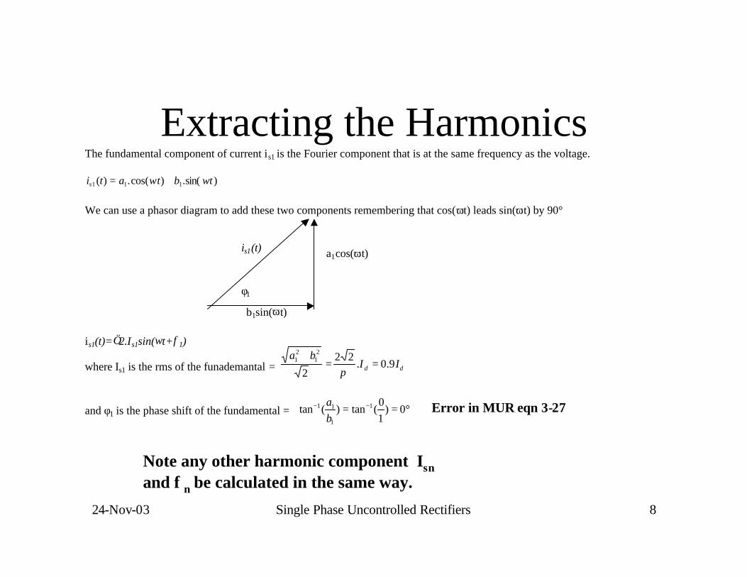
Extracting the Harmonics The fundamental component of current is1 is the Fourier component that is at the same frequency as the voltage.
)sin(.)cos(.)( 111 tbtatis ωω += We can use a phasor diagram to add these two components remembering that cos(ωt) leads sin(ωt) by 90° is1(t)=√2.Is1sin(ωt+φ1)
where Is1 is the rms of the funademantal = dd IIba
9.0.22
2
21
21 ==
+π
and φ1 is the phase shift of the fundamental = °== −− 0)10
(tan)(tan 1
1
11
ba
is1(t)
b1sin(ωt)
a1cos(ωt)
φ1
Error in MUR eqn 3-27
Note any other harmonic component Isnand φn be calculated in the same way.

24-Nov-03 Single Phase Uncontrolled Rectifiers 9
• Current is not a sinewave => Power factor is not merely cos(φ)
• Can use the more general definition of power factorPF= Real Power / Apparent Power = P/SFor rectifier described above:
Power Factor with non-sinusoidal current
9.022
.
.22
==
==π
π
ss
ss
IV
IV
SP
PF

24-Nov-03 Single Phase Uncontrolled Rectifiers 10
Displacement Power Factor
• The displacement power factor (DPF) is the power factor that would arise from the phase shift of the fundamental
DPF = cos(φ1) For the rectifier we are looking at DPF = cos(0)=1
• If the voltage is a pure sinewave then only the fundamental component of current gives real power and the overall power factor (PF) in the presence of harmonics is lower by the ratio of the rms of the fundamental to the overall rms.
PF=P/S=DPF.Is1/Is
For the rectifier we are looking at PF = 1x0.9Id/Id=0.9 so all of the power factor reduction in this case comes from harmonics

24-Nov-03 Single Phase Uncontrolled Rectifiers 11
A useful trick with rms quantities
• We can express a repetitive waveform as the sum of harmonic components:
• If we square and integrate on the way to getting the rms (Is) the cross product terms integrate to zero. So the overall rms becomes:
• This is usually expressed as :
• The above is an extremely useful equation relating the rms, the dc component, the fundamental and the distortion of a waveform
....)sin(.2)sin(.2)( 22110 +++++= φωφω tItIIti ssss
.....23
22
21
20
2 ++++= sssss IIIII
221
22dissdcs IIII ++=

24-Nov-03 Single Phase Uncontrolled Rectifiers 12
Total Harmonic Distortion• Total harmonic distortion (THD) is an index used to quantify the
amount of distortion in a waveform• THD is defined as
• If the waveform has no dc component then THD can be calculated as:
• If the voltage is sinusoidal then only the fundamental component of current gives rise to useful power. The harmonic components give rise to excess heating in cables and may interfere with other equipment. Ideally THD should be as close to 0% as possible. The rectifer wwe have examined has a THD of
%100.1s
dis
II
THD =
%100.1
21
2
s
ss
III
THD−
=
%48%100.9.0
)9.0( 22
=−
=d
dd
III
THD

24-Nov-03 Single Phase Uncontrolled Rectifiers 13
Effect of Source Inductance
Vd
id
vd
Is
VLs

24-Nov-03 Single Phase Uncontrolled Rectifiers 14
Source Inductance Waveforms
Aµ
ω t µ π 0
ω t µ π 0
i s
ω t µ π 0
v l s
ω t µ π 0
i d 1
v d

24-Nov-03 Single Phase Uncontrolled Rectifiers 15
Effects of source inductance
• It takes time for the current in Ls to reverse. During the commutation interval µ (in radians) the voltage vd Is clamped to zero.
• Effects of source inductance:Average output voltage is reduced LDisplacement power factor is dis-improved LTHD is usually improved ☺

24-Nov-03 Single Phase Uncontrolled Rectifiers 16
EquationsDuring Commutation vd = 0 so vls = vs and the current is in Ls must change from -Id to +Id.
µ
µωµ
ωω
ωAtdvdtviLvv
dtdi
Ls ssssslss .
1..
1...
0
)(
0===∆⇒== ∫∫
but ∆is=2Id so Aµ=2.ω.Ls.Id
solving the integral equation we can show that s
ds
VIL.2
1)cos(ω
µ −=
The output voltage Vd is still the average of vd but this time it vd has a chunk equal to Aµ taken out once every π radians.
π
ωππ
µ dssdod
ILV
AVV
..2.
22 −=−=

24-Nov-03 Single Phase Uncontrolled Rectifiers 17
Problem 3
• One of the diodes in a bridge rectifier has failed open circuit. You may assume that all components are ideal. The load is highly inductive and source inductance may be neglected1. Plot the circuit waveforms (vs(t), is(t), diode currents, vd(t))2. Derive expressions for output DC voltage (Vd ), Input Power factor (PF),
Displacement power factor (DPF) and total harmonic distortion (THD)3. Build a spice model of the circuit and use it to verify your answers.
Hints: a) The circuit will behave like a half wave rectifier.b) Is
2 = Idc2 + Is1
2 + Idis2
c) Suggested values for simulation vs(t): 100V peak (70Vrms), 50HzL1=100H, Rload = 100

24-Nov-03 Single Phase Uncontrolled Rectifiers 18
Bridge Rectifier with Capacitive Load

24-Nov-03 Single Phase Uncontrolled Rectifiers 19
Assumptions
• Ideal Diodes• Highly Capacitive
RC >>T => Capacitor voltage not vary over course of cycle =>Like a constant voltage source load
• Current is zero prior to every zero crossing of voltage => Commutation interval is zero.

24-Nov-03 Single Phase Uncontrolled Rectifiers 20
Rectifier with Constant voltage Source Load
id
is

24-Nov-03 Single Phase Uncontrolled Rectifiers 21
Rectifier with a dc-side voltage

24-Nov-03 Single Phase Uncontrolled Rectifiers 22
DC-Side Voltage and Current Relationship
• Zero current corresponds to dc voltage equal to the peak of the input ac voltage

24-Nov-03 Single Phase Uncontrolled Rectifiers 23
Effect of DC-Side Current on THD, PF and DPF
• Very high THD at low current values

24-Nov-03 Single Phase Uncontrolled Rectifiers 24
Crest Factor versus the Current Loading
• The Crest Factor is very high at low values of current

24-Nov-03 Single Phase Uncontrolled Rectifiers 25
Diode-Rectifier with a Capacitor Filter
• Power electronics load is represented by an equivalent load resistance

24-Nov-03 Single Phase Uncontrolled Rectifiers 26
Line-Voltage Distortion
• PCC is the point of common coupling

24-Nov-03 Single Phase Uncontrolled Rectifiers 27
Line Voltage Distortion
• Real Life AC line has some source impedance ( usually inductive Ls1)• The harmonic current components will cause a harmonic voltage to
appear across this impedance
• The harmonic component of vpcc is:
• Note that the inductive nature of source impedance will tend to amplify the effect of harmonics at higher frequencies
dtdi
Lvv ssspcc 1−=
∑ ≠−=
11)(n
snsdispcc dt
diLv

24-Nov-03 Single Phase Uncontrolled Rectifiers 28
• Distortion in voltage supplied to other loads
Line-Voltage Distortion

24-Nov-03 Single Phase Uncontrolled Rectifiers 29
Voltage Doubler Rectifier
• In 115-V position, one capacitor at-a-time is charged from the input.

24-Nov-03 Single Phase Uncontrolled Rectifiers 30
Effect of Harmonics on Neutral Current
• Three Phase system – normally expect phase currents to sum to zero so no neutral or a very light neutral wire is required
• But if there are a lot of single phase rectifiers on each of the phases – Triplen Harmonics add cumulatively so neutral wire can carry a significant 3rd harmonic component
• See MUR section 5-5 for example.