Embed Size (px)
Citation preview
LIMUS: Exploration of Technological Prototypes forLocation-Based Services in Museums ?
Juan D. Gutierrez, Fernando J. Aranda, Teodoro Aguilera andFernando J. Alvarez
Department of Electrical Engineering, Electronics and AutomationSensory Systems Research Group (https: // giss. unex. es/ )
University of Extremadura, Badajoz, Spain (06006)[email protected]
Abstract. This paper explores three technologies: acoustic, visible light, and BluetoothLow Energy (BLE) to provide Location-Based Services (LBS) in museums or archaeologicalsites. Acoustic and visible light beacons have been specifically designed, whereas for BLE acommercial beacon has been chosen. Also, a mobile phone application has been developedwhich implements the identification algorithms for each proposed technology. Once theartwork has been identified, its information is displayed on the mobile phone screen.A set of experimental tests has been carried out in order to evaluate the performance ofeach technology. Results have shown a robust detection radius of 1.5 m around the acousticand BLE beacons, while this radius decreases to 0.5 m for the visible light beacon. Resultshave also revealed the existence of some phenomena that worsen the detection quality incertain areas. This should be addressed in an evolved version of this work.
Keywords: Location-Based Services (LBS), Cell-ID, Acoustics, Bluetooth Low Energy(BLE), Visible Light, Museum.
1 Introduction
Location-Based Services (LBS) constitute the main reason that has fostered an intense researchactivity in the field of Local Positioning Systems (LPS). They can be generally defined asinformation services accessible with mobile devices through the mobile network and utilizingthe ability to make use of the mobile device location [6]. In that sense, this work presents thedevelopment of a smartguide for archaeological sites in the Spanish region of Extremadura andthe Portuguese region of the Alentejo (The LIMUS project [4]). This project aimed to design acommon application for all visitors of a number of sites from the aforementioned regions, siteswith very distinct characteristics that may require different tag identification technologies. Threeof these technologies, namely acoustic, Bluetooth Low Energy (BLE), and visible light were finallyselected to conduct a comparative analysis of performance. The results are presented in this work.
The paper is organized as follows. Section 2 details the characteristics and components ofeach prototype. Section 3 explains the transmitter and receiver architectures for each technology.Section 4 presents the main results obtained in the experiments that have been carried out.Finally, Section 5 highlights the most relevant conclusions drawn from this work.
? This work was supported in part by the European Commission through the Project LIMUS underGrant 0246-LIMUS-4-E, in part by the Spanish Government and the European Regional DevelopmentFund (ERDF) through the Project MICROCEBUS-UEx under Grant RTI2018-095168-B-C54, and inpart by the Regional Government of Extremadura and ERDF-ESF under Project GR18038.
2 Juan D. Gutierrez et al.
2 Beacons Description
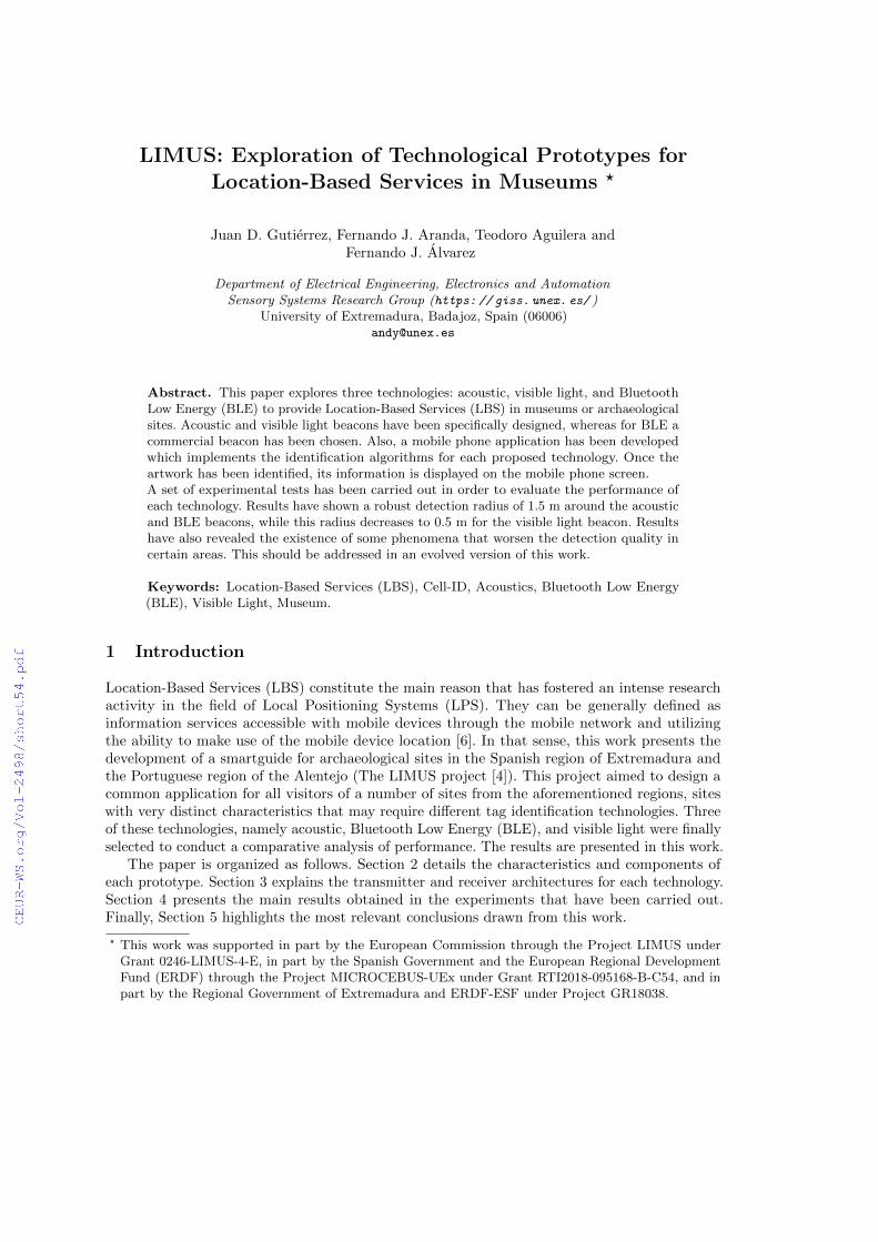
This section describes the beacons used, which are based on three different technologies: acoustic,BLE, and visible light. For each beacon, its appearance, dimensions, and components are described.For acoustic and visible light technologies, the beacons have been specifically designed to optimisethe size, price, and quality of emissions. However, for BLE technology, a commercial beacon hasbeen chosen, since this technology has long been used in mobile phones.
STM32L432KC
AC/DC C
onverter
Transducer
Mounted Beacon
55 mm
55 mm42 mm
Audio
Amplifier(underside)
(a) Acoustic beacon. (b) Estimote Proximity BLE bea-con.
118 mm
39 mm
Adafruit Feather HUZZAH
Shar
p
PC
123
(c) Visible light beacon.
Fig. 1: Beacon description for each proposed technology.
Acoustic technology offers numerous advantages when it is used to implement systems thatprovide LBS. Among them, the narrow emission cone of the acoustic transducer makes it possibleto discriminate between areas very close to each other. In addition, the acoustic waves will beconfined in each museum room and detections from adjacent rooms will be avoided.
Fig. 1a shows on the right the inside of the beacon where an AC/DC converter, a NUCLEO-L432KC board and a KSSG1708 transducer can be seen. To the left of the figure can be seen thebeacon mounted inside a plastic box of dimensions 55×55×42 mm. This box has a perforationthat allows the programming of the STM32L432KC module via its Micro-USB port. Furthermore,the beacon can be connected directly to the mains supply network without having to replace itsbatteries periodically.
Finally, this technology is suitable for the emission of robust signals against noise and theDoppler effect. This robustness makes it possible to implement modulations in long sequencesgenerating 8 or even 16 bit encoding that can identify a large number of different exhibits.
The BLE beacons used for the LIMUS project are the Estimote BLE Proximity Beacons.As shown in Fig. 1b, these beacons have a low-power 32 bit and 64 MHz Central Processing Unit(CPU), a set of sensors (accelerometer, barometer, thermometer, magnetometer and photometer)and a Bluetooth antenna all over a circuit board. This device is powered by a set of batteries andwrapped in a plastic color case. Each beacon can broadcast multiple signals at the same time,using different emission powers and advertising periods. Estimote beacon’s settings can be donevia their smartphone application or cloud service. This beacon is shown in Fig. 1b.
Visible light beacon’s final arrangement on a stand, as well as the beacon’s insides, with itscomponents identified, is shown in Fig. 1c. In particular, the beacon control and interruption circuitwhich modulates the light signal is implemented on a Feather HUZZAH board manufacturedby Adafruit. The combination of the CMOS cameras rolling shutter effect, the high frequency
LIMUS: Exploration of Technological Prototypes for LBS in Museums 3
LED luminaries modulation, and the human eye’s inability to perceive them are the basis of thissystem [2]. Thus, it is possible to emit a luminous message without annoying people close tosource.
3 Systems Operation
This section shows the beacons architecture. The transmitter operation for each technology ispresented, as well as the particularities of their own receivers.
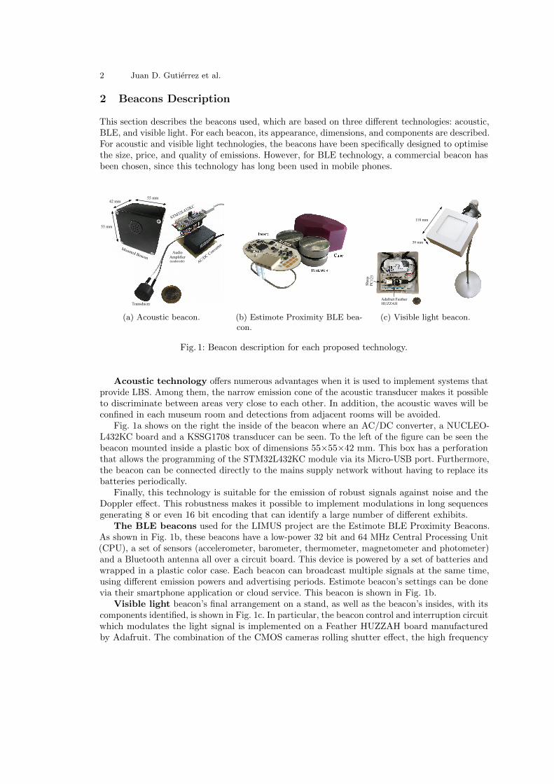
Fig. 2 shows the operating diagrams of both the transmitter and receiver modules for theacoustic technology. The transmitter module consists of an AC/DC converter in charge ofsupplying the STM32L432KC board. This board has a microcontroller STM32F103CBT6 thatgenerates the digital signals. Subsequently, these signals pass through the board’s digital-to-analogconverter (DAC), to finally be sent to the amplifier in order to be synthesized using an acoustictransducer. The receiver module is implemented in an Xiaomi Mi 8 Android terminal. The phoneacquires the acoustic signals through its embedded microphone. These signals are then processedby the phone’s analog-to-digital converter (ADC). The resulting signal is first passed througha matched filter with a synchronization chirp (initChirp). The compressed pulse detection ofthis chirp indicates the beginning of the signal fragment where the information of the exhibit tobe decoded is located. To decode this information, this signal fragment will be sent to two newfilters. A first matched filter with the upChirp pattern determines the location of the compressedpulses corresponding to the chirps encoding the 1s, and a second matched filter now with thedownChirp pattern determines the location of the compressed pulses identifying the 0s of thebinary code. Then, in the decision module, the signals resulting from the matched filters aredivided into sections of duration Tb (bit period). Both filtered signals are compared sectionby section, assigning the value 1 or 0 to the bit depending on whether the absolute maximumvalue for both filtered signals in the section in question corresponds to the pattern upChirp ordownChirp respectively. Finally, an 8 bit binary code will be obtained which identifies the artworkin question. In addition, the use of frequencies in the audio’s upper spectrum, together with thevery low power emission that allows the chirp’s pulse compression, makes the emission of thesesignals practically imperceptible to the users.
Decision
Binary Code
ADC
Matched Filter
initChirp
Peak Detector Data Signal
Data Beginning
Tb
Matched Filter
upChirp
Matched Filter
downChirp
Peak Detector
Peak Detector
Transmitter Module
Receiver Module
DAC
Audio Amplifier STM32F103CBT6
MicrocontrolerAC/DC Converter
STM32L432KC Board
Tb
Fig. 2: Operating diagram of the transmitter and receiver acoustic modules.

4 Juan D. Gutierrez et al.
The parameter used for positioning with BLE is the Received Signal Strength Indicator(RSSI). This value measures signal attenuation in a logarithmic scale and can be obtained from asmartphone device. RSSI decreases with the square of the distance from the source, but indoorsmultipath effect and emission frequency changes make measurements disperse and time variant [1].The smartphone used as receiver performs a periodic scanning process, searching for other BLEdevices in the surroundings. In each scanning, RSSI results are sorted from highest to lowest.The output code is the one associated with the first element of the list provided that its RSSIis above a threshold value, U1. This value is fixed to detect the code in the proximity of thebeacon, otherwise the system can detect the code even at large distance inside the BLE maximumtransmission range.
There could be situations when nearby beacons have high RSSI readings and all values areabove the threshold U1. In order to avoid detections in these situations, the RSSI of the secondelement of the sorted list must be smaller than a second threshold, U2. Finally the whole processmust be repeated three times to correctly identify the code and avoid false positive identifications.The whole process is shown in Fig. 3, where χRSSIi is the output code of the system.
StartBLE
Scanning
RSSISorting
RSSI1 > U1 RSSI2 < U2 j ≤ n
χRSSIi
j = 0 j = 0 j + +
yes
no
yes
no
yes
no
Fig. 3: BLE proposed code identification.
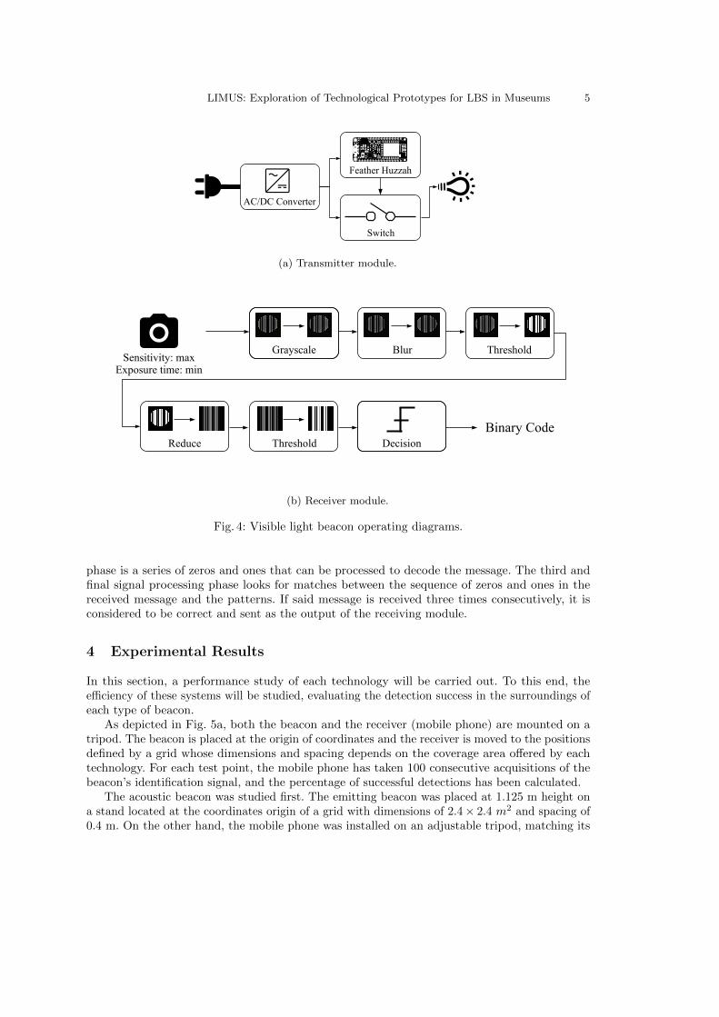
Fig. 4a shows the operating diagram of the visible light beacon transmitter module, while theblock diagram that describes the acquisition and further signal processing is shown in Fig. 4b.The transmitter module needs two AC/DC converters, the first for the LED panel, the secondfor the Feather HUZZAH development board, which is used to interrupt the power supply withthe help of an optocoupler. The board is programmed to convert the message to a Manchesterencoding via on-off keying (OOK). The LED panel turns off completely to transmit a 0 and lightsup to transmit a 1, at an oscillation frequency of 5 kHz.
The Android app visible light detection module uses the rear camera of the terminal for theacquisition of the signal. First, the sensitivity of the camera is increased to the maximum, whileits exposure time is reduced as much as possible. As a result, the luminous parts of the capturedscene are more prominent than the rest, giving priority to luminaries. A single photograph isenough to carry out a complete decoding process. This process is repeated as many times persecond as the capacity of the smartphone allows, twice in this work.
First, the acquired image is converted to gray scale, since only the intensity of the signal, notits chromatic components, are of interest. Next, the signal noise is reduced using a Gaussiansmoothing function. Finally, a thresholding operation is performed, resulting in a black and whiteimage. Otsu’s algorithm [3] is applied to obtain the optimal threshold value. The second phase ofprocessing begins with a reduction operation applied to the image columns, using the average ofall the values. Otsu’s thresholding is reapplied to the value vector obtained. The result of this
LIMUS: Exploration of Technological Prototypes for LBS in Museums 5
Feather Huzzah
USB
RST NC3V NC
ADC
14 213 15 0
SCK MO MI
5 4
RX TX
BAT12 16
GND
#0
EN
CHPD
RST
CHG
NC
NC NC NC
SCL SDA
huzzah!
Antenna
Switch
AC/DC Converter
(a) Transmitter module.
Sensitivity: maxExposure time: min
Grayscale
Binary CodeDecision
Blur Threshold
Reduce Threshold
(b) Receiver module.
Fig. 4: Visible light beacon operating diagrams.
phase is a series of zeros and ones that can be processed to decode the message. The third andfinal signal processing phase looks for matches between the sequence of zeros and ones in thereceived message and the patterns. If said message is received three times consecutively, it isconsidered to be correct and sent as the output of the receiving module.
4 Experimental Results
In this section, a performance study of each technology will be carried out. To this end, theefficiency of these systems will be studied, evaluating the detection success in the surroundings ofeach type of beacon.
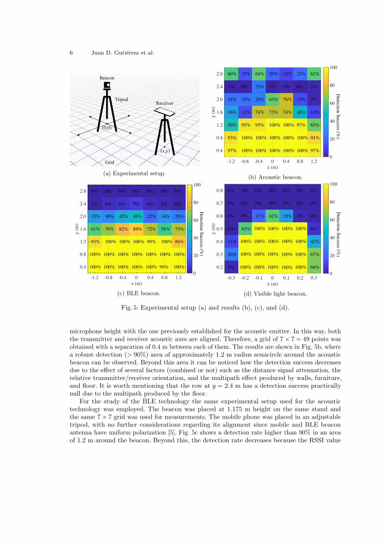
As depicted in Fig. 5a, both the beacon and the receiver (mobile phone) are mounted on atripod. The beacon is placed at the origin of coordinates and the receiver is moved to the positionsdefined by a grid whose dimensions and spacing depends on the coverage area offered by eachtechnology. For each test point, the mobile phone has taken 100 consecutive acquisitions of thebeacon’s identification signal, and the percentage of successful detections has been calculated.
The acoustic beacon was studied first. The emitting beacon was placed at 1.125 m height ona stand located at the coordinates origin of a grid with dimensions of 2.4 × 2.4 m2 and spacing of0.4 m. On the other hand, the mobile phone was installed on an adjustable tripod, matching its
6 Juan D. Gutierrez et al.
Beacon
ReceiverTripod
Grid
(0,0)
(x,y)
(a) Experimental setup.
97%
93%
50%
36%
24%
1%
60%
100%
100%
95%
13%
24%
0%
15%
100%
100%
95%
74%
28%
25%
64%
100%
100%
100%
73%
63%
1%
20%
100%
100%
100%
74%
76%
3%
12%
100%
100%
97%
48%
13%
0%
22%
97%
91%
65%
12%
2%
2%
62%
Detection Success (%
)
-1.2 -0.8 -0.4 0 0.4 0.8 1.2x (m)
0.4
0.8
1.2
1.6
2.0
2.4
2.8
y (m
)
0
20
40
60
80
100
(b) Acoustic beacon.
100%
100%
93%
61%
35%
1%
0%
100%
100%
100%
70%
30%
4%
0%
100%
100%
100%
82%
42%
6%
0%
100%
100%
100%
89%
49%
9%
0%
100%
100%
99%
72%
22%
4%
0%
99%
100%
100%
58%
34%
2%
0%
100%
100%
86%
73%
28%
0%
0%D
etection Success (%)
-1.2 -0.8 -0.4 0 0.4 0.8 1.2x (m)
0.4
0.8
1.2
1.6
2.0
2.4
2.8
y (m
)
0
20
40
60
80
100
(c) BLE beacon.
3%
26%
11%
0%
0%
0%
0%
100%
100%
100%
62%
0%
0%
0%
100%
100%
100%
100%
21%
0%
0%
100%
100%
100%
100%
62%
0%
0%
100%
100%
100%
100%
35%
0%
0%
100%
100%
100%
100%
3%
0%
0%
66%
67%
42%
6%
0%
0%
0%
Detection Success (%
)
-0.3 -0.2 -0.1 0 0.1 0.2 0.3x (m)
0.2
0.3
0.4
0.5
0.6
0.7
0.8
y (m
)
0
20
40
60
80
100
(d) Visible light beacon.
Fig. 5: Experimental setup (a) and results (b), (c), and (d).
microphone height with the one previously established for the acoustic emitter. In this way, boththe transmitter and receiver acoustic axes are aligned. Therefore, a grid of 7 × 7 = 49 points wasobtained with a separation of 0.4 m between each of them. The results are shown in Fig. 5b, wherea robust detection (> 90%) area of approximately 1.2 m radius semicircle around the acousticbeacon can be observed. Beyond this area it can be noticed how the detection success decreasesdue to the effect of several factors (combined or not) such as the distance signal attenuation, therelative transmitter/receiver orientation, and the multipath effect produced by walls, furniture,and floor. It is worth mentioning that the row at y = 2.4 m has a detection success practicallynull due to the multipath produced by the floor.
For the study of the BLE technology the same experimental setup used for the acoustictechnology was employed. The beacon was placed at 1.175 m height on the same stand andthe same 7 × 7 grid was used for measurements. The mobile phone was placed in an adjustabletripod, with no further considerations regarding its alignment since mobile and BLE beaconantenna have uniform polarization [5]. Fig. 5c shows a detection rate higher than 90% in an areaof 1.2 m around the beacon. Beyond this, the detection rate decreases because the RSSI value
LIMUS: Exploration of Technological Prototypes for LBS in Museums 7
is below the U1 threshold. Since consecutive RSSI measurements are very sparse, the changein the detection rate is not abrupt, with a small region featuring a detection rate around 50%.The threshold defines an area around the beacon where code detection is expected. Thresholdincrease or decrease changes the area with a high detection rate, thus it must be fixed beforehandaccording to the location and the minimum separation between exhibits.
A grid of 60× 60 cm, with cells of 10× 10 cm, was prepared for testing the visible light beaconperformance. The light source was located 20 cm away from the middle of the grid. The center ofthe transmitter was located at 1 m height, as it was the camera optical axis. Both transmitter andreceiver where parallel to each other. Given the differences in coverage between the two previoustechnologies and this one, using the same grid for the three experiments would have less accurateresults for the case of visible light. There is a clear limit marked at a distance of about y = 0.5 mwhere the success rate decreases rapidly, as shown in Fig. 5d. For longer distances, detection isunfeasible due to the physical limitations imposed by the size of the emitting source, the cameraresolution, and interference from other light sources present in the environment.
5 Conclusions
This work has explored different Location Based Services (LBS) technologies for mobile phones inmuseum environments. Concretely, acoustic technology, Bluetooth Low Energy (BLE), and visiblelight have been evaluated. Acoustic and visible light transmitter beacons have been specificallydesigned. Since BLE is a consolidated technology, an available commercial beacon has been chosen.Besides, the design and operation principle of each beacon has been explained. Also, the designof the mobile phone code detection algorithm for each technology has been described.
Moreover, an experimental study of detection robustness in the surroundings of each beaconhas been carried out. This study shows that both the acoustic technology and BLE beacons havea robust detection radius of about 1.5 m around the beacon where the percentage of detections isabove 90%. However, the visible light beacon detection radius is lower, around 0.5 m. Accordingto the results, the three technologies have zones where the detection percentage decreases due todifferent factors that mask or deteriorate the signal. These issues should be addressed in laterdevelopments of this work.
References
1. Faragher, R., Harle, R.: Location fingerprinting with Bluetooth Low Energy beacons. IEEE Journalon Selected Areas in Communications 33, 1–1 (11 2015). https://doi.org/10.1109/JSAC.2015.2430281
2. Gutierrez, J.D., Alvarez, F.J., Aguilera, T., Paredes, J.A., Morera, J.: Visible Light Positioning forSmartphones Based on Biphase Mark Coding: A Proof of Concept. In: 2018 International Conferenceon Indoor Positioning and Indoor Navigation (IPIN) (2018)
3. Otsu, N.: A Threshold Selection Method from Gray-Level Histograms. IEEE Transactions on Systems,Man, and Cybernetics 9(1), 62–66 (Jan 1979). https://doi.org/10.1109/TSMC.1979.4310076
4. Sensory Systems Research Group: Presentation of the Limus project, https://giss.unex.es/2019/03/21/presentation-of-the-limus-project/
5. The Bluetooth Special Interest Group: Kirkland, WA, USA: Specification of the Bluetooth System,Covered Core Package, Version: 4.0
6. Virrantaus, K., Markkula, J., Garmash, A., Terziyan, Y.: Developing GIS-supported location- basedservices. In: First International Workshop on Web Geographical Information Systems (WGIS 2001). p.423–432. Kyoto, Japan (2001)