Embed Size (px)
Citation preview

UN
CO
NTR
OLL
ED IF
PR
INTE
DELECTRICAL AND MECHANICAL VEHICLE D 323 ENGINEERING INSTRUCTIONS Issue 2, Jun 07
1
TRUCK, WRECKER, HEAVY, MC3, 8 TONNE (MACK), ARMY (AUST) 6778 NSN 2320-66-151-7176
LIGHT GRADE REPAIR
This instruction is authorised for use by command of the Chief of Army. It provides direction, mandatory controls and procedures for the operation, maintenance and support of equipment. Personnel are to carry out any action required by this instruction in accordance with EMEI General A 001.
TABLE OF CONTENTS Page No Page No
LIST OF FIGURES 2 LIST OF TABLES 3 INTRODUCTION 4 ASSOCIATED PUBLICATIONS 4 ROTABLE ITEM IDENTIFICATION 5 SPECIAL TOOLS 6 GROUP 1 – ENGINE 6 GROUP 2 – COOLING SYSTEM 6
Fan and Pneumatic Fan Clutch 6 Fan Clutch Air Filter and Solenoid Valve 7 Fan Clutch Thermal Switch 8 Radiator 8 Fault Finding 8
GROUP 3 – EXHAUST SYSTEM 10 GROUP 4 – FUEL SYSTEM 10
Hand Throttle 10 Throttle Control Valve (Recovery System) 10 Air Filters 11 Speed Limiter 11
Solenoid Valve 11 GROUP 5 – CLUTCH 12
Clutch Pedal and Cable 12 Solo Clutch Maintenance 12
GROUP 6 – TRANSMISSION 19 Air System 19
Air Filter Regulator 19 Shifting Controls 19
Roadranger Valve 19 Gear Shift Lever Housing 20
Inspection Points 20 Auxiliary Section 21
Output Seal and Drive Yoke 21 Preventative Maintenance 22
In Vehicle Checks 22 Checks with Driveline Dropped 22 Checks with Drive Yoke Removed 22
Air System Fault Finding 22 Transmission Oil Cooler 24 Fault Finding 24
GROUP 7 – TRANSFER CASE 26 GROUP 8 – PROPELLER SHAFTS 26 GROUP 9 – REAR AXLES 26 GROUP 10 – FRONT AXLE 26 GROUP 11 – WHEELS, RIMS AND TYRES 26 GROUP 12 – BRAKE SYSTEM 26
Work Brake Control Valve 26 Brake Testing 27
GROUP 13 – SUSPENSION 29 GROUP 14 – STEERING 29 GROUP 15 – ELECTRICAL 29
Recovery Electrical System 29 Lighting 29
Revolving Lamps 29 Crew Cabin Interior Lights 29
Reversing Camera System 30 Monitor 30 Cameras 30
Military Radio Mounts, Fittings and Cables 30 General 30 Radio Cabling to VHF Antenna and HF Tuner 30
Radio/CD Player 31 GROUP 16 – FRAME 31 GROUP 17 – BODY 31
Body 31 Cab Isolation System 31
UN
CO
NTR
OLL
ED IF
PR
INTE
DVEHICLE D 323 ELECTRICAL AND MECHANICAL Issue 2, Jun 07 ENGINEERING INSTRUCTIONS
2
TABLE OF CONTENTS (Cont.) Page No Page No
GROUP 18 – CAB HEATING/COOLING 32 POWER TAKE-OFFS 32
PTO Control Valves 32 HYDRAULIC SUPPLY SYSTEM 32
Flaretite Seals 32 Relieving Hydraulic Pressure 32 Return Line Oil Filters 32 Filter Head 33 Oil Cooler 33 Bleeding Hydraulic Circuits 34
RECOVERY PLATFORM 35 Mechanical Systems 35
Hitch Assembly 35
Sheave Head Assembly 35
Rear Self Recovery Sheave 38
Reversing Sheaves 38 Recovery Frame Repair 39 Hydraulic System 39
Tow Cylinders 39 Main Lift Cylinder 39 Spade Cylinders 39 Control Valve 40
Recovery Control Systems 40 Control Valve Cables 40
Recovery Control Panels 41 Inspection and Testing 41 Fault Finding 41
PNEUMATIC SYSTEM 42 Pneumatic Supply Manifold 42
Recovery Pneumatic System 42 Pneumatic System Lubricator Adjustment 42
WINCHES 43 Winch Inspection and Testing 43 Winch Rope 46 Drum Brake (drag brake) 46 Programmable Logic Controller (PLC) 46 Winch Assembly 46 Secondary Drive Motor (OMH 200) 46
Secondary Drive A Gear Assembly 47 Hydraulic Valve Block 48 Secondary Drive Motor B (OMT 200) 48 Secondary Drive B Gear Assembly 49
Pneumatic Disengagement Cylinder 50 Fault Finding 51
PALFINGER CRANE PK-9501 55 Hydraulics 55
Hydraulic Pipes and Hoses 56 High Pressure Filter 56 Stabiliser Leg Cylinder 56 Stabiliser Control Valve 57
Crane Electronics 57 General 57 Paltronic 50 System Fault Finding 57 Paltronic 50 Codes 58 Fault Finding – Crane 67 Radio Control System 67 Testing of Radio Transmitter 68
LIST OF FIGURES Figure No Title Page No Figure No Title Page No
Figure 1 Truck, Wrecker, Heavy, MC3, 8 Tonne (Mack), Army (Aust) 6778 4
Figure 2 Transmission Output Seal Driver 6 Figure 3 Fan Clutch Circuits 7 Figure 4 Clutch Locking Screws 7 Figure 5 Horton Air Filter and Solenoid Valve 8 Figure 6 Fan Clutch Air Filter and Solenoid 8 Figure 7 Fan Clutch Thermal Switch 8 Figure 8 Hand Throttle Engine Bay 10 Figure 9 Hand Throttle Cabin 10 Figure 10 Throttle Pressure Reducing Valve 10 Figure 11 Speed Limiter Solenoid Valve 11 Figure 12 Movement of Wear Indicator Tab 12
Figure 13 Clutch Linkage Adjustment 12 Figure 14 Clutch Wear Indicator 13 Figure 15 Clutch Free Pedal 13 Figure 16 Transmission 19 Figure 17 Transmission Air Lines 20 Figure 18 Gear Shift Lever Housing 20 Figure 19 Rear Bearing Cover and Drive Yoke 22 Figure 20 Range Cylinder 24 Figure 21 Transmission Oil Cooler 24 Figure 22 Work Brake Control Valve 26 Figure 23 Crew Cab Light 30 Figure 24 Reversing Camera 30
UN
CO
NTR
OLL
ED IF
PR
INTE
DELECTRICAL AND MECHANICAL VEHICLE D 323 ENGINEERING INSTRUCTIONS Issue 2, Jun 07
3
Figure 25 Radio/CD Player Removal 31 Figure 26 Cab Isolation – Rear Air Spring Station 31 Figure 27 Hydraulic Reservoir and Oil Filters 33 Figure 28 Oil Cooler Assembly 33 Figure 29 Oil Cooler Bypass Valve 34 Figure 30 Hitch Assembly 37 Figure 31 Removal of Control Module Plug 40 Figure 32 Recovery System Control Valve Cables 41 Figure 33 Pneumatic Supply Manifold 42 Figure 34 Right Winch 43 Figure 35 Winch Hydraulic Circuit 45 Figure 36 Drum Brake 46 Figure 37 PLC 47 Figure 38 Secondary Drive Assembly A 48 Figure 39 Secondary Drive Assembly B 49 Figure 40 Pneumatic Disengagement Cylinder 50 Figure 41 Pin Engagement Measurement 51 Figure 42 Basic Crane Components 55
Figure 43 WEO Plug-In Fitting 56 Figure 44 Stabiliser Control Valve 57 Figure 45 Paltronic 50 Display Unit 58 Figure 46 Paltronic Display 50 Unit Connections 58 Figure 47 Crane Electronic and Remote Control Boxes 58 Figure 48 Paltronic 50 Basic Unit and Control Valve
Circuit Boards 59 Figure 49 Remote Control Receiver 67 Figure 50 Brake System Circuit Diagram 71 Figure 51 Recovery System Pneumatic Circuit 73 Figure 52 Recovery System Hydraulic Circuit 75 Figure 53 HRV Specific Cab/Chassis Electrical Circuit
Diagram 77 Figure 54 Recovery System Electrical Circuit Diagram 79 Figure 55 Recovery System Remote Control Circuit
Diagram 81 Figure 56 Crane Spool Valve Hydraulic Circuits 83 Figure 57 Crane Actuator Hydraulic Circuits 85 Figure 58 Crane Electrical Circuit Overview 87
LIST OF TABLES Table No Title Page No Table No Title Page No
Table 1 – Rotable Item Identification 5 Table 2 Fan Clutch Fault Finding 9 Table 3 Clutch Fault Finding 14 Table 4 Transmission Torque Settings 19 Table 5 Transmission Fault Finding 24 Table 6 Flaretite Seal Torque Settings 32 Table 7 Recovery System Pin Wear Limits 38 Table 8 Recovery System Fault Finding 42 Table 9 Winch Fastener Torques 43
Table 10 Winch Fault Finding 52 Table 12 Crane Fastener Torque Settings 55 Table 12 Legend to Paltronic 50 Basic Unit and Control
Valve Circuit Boards 60 Table 13 Paltronic 50 Standard Codes 61 Table 14 Paltronic 50 Flashing Codes 63 Table 15 Paltronic 50 Additional Information Codes 66 Table 16 Fault Finding – Crane Hydraulic System 67 Table 17 Fault Finding – Remote Control Receiver 69

UN
CO
NTR
OLL
ED IF
PR
INTE
DVEHICLE D 323 ELECTRICAL AND MECHANICAL Issue 2, Jun 07 ENGINEERING INSTRUCTIONS
4
Figure 1 Truck, Wrecker, Heavy, MC3, 8 Tonne (Mack), Army (Aust) 6778
INTRODUCTION
WARNING
Drain air from the trucks air system prior to removal of air lines or air system components.
Disconnect the vehicle batteries and remove both plugs from the winch programmable logic controller (plc) boxes prior to commencing any welding tasks.
The engine, clutch, transmission and body components of this vehicle have been significantly modified from the standard configuration of mack r series fleet vehicles. It is therefore imperative that instructions detailed in this emei are strictly followed to
prevent the performance of incorrect maintenance procedures.
1. This EMEI supplement contains light repair level instructions for removing, repairing, replacing and installing minor components fitted to the Truck, Wrecker, Heavy, MC3, 8 Tonne (Mack), Army (Aust) 6778 as shown in Figure 1. For further information on the base truck refer to the relevant references.
ASSOCIATED PUBLICATIONS
2. For technical data pertaining to the base truck, repair procedures and other relevant information, reference may be necessary to the latest issue of the following documents:
a. EMEI Vehicle D 320 – Truck, Wrecker, Heavy, MC3, 8 Tonne (Mack), Army (Aust) 6778 – Data Summary;
b. EMEI Vehicle D 322 – Truck, Wrecker, Heavy, MC3, 8 Tonne (Mack), Army (Aust) 6778 – Technical Description;
c. EMEI Vehicle G 702 – Truck, Cargo, Heavy, MC3, (Mack) – Technical Description;

UN
CO
NTR
OLL
ED IF
PR
INTE
DELECTRICAL AND MECHANICAL VEHICLE D 323 ENGINEERING INSTRUCTIONS Issue 2, Jun 07
5
d. EMEI Vehicle G 702-1 – Truck, Cargo, Heavy, MC3, (Mack), All Types, Air Spring Suspension System (SA441W) – Technical Description;
e. EMEI Vehicle G 703 – Truck, Cargo, Heavy, MC3, (Mack) – Unit Repair;
f. EMEI Vehicle D 324-1 – Truck, Wrecker, Heavy, MC3, 8 Tonne (Mack), Army (Aust) 6778 – Medium Repair;
g. EMEI Vehicle G 704 – Truck, Cargo, Heavy, MC3, (Mack) – Field Repair;
h. EMEI Vehicle D 324-2 – Truck, Wrecker, Heavy, MC3, 8 Tonne (Mack), Army (Aust) 6778 – Heavy Repair;
i. EMEI Vehicle G 704-1 – Truck, Cargo, Heavy, MC3, (Mack) – Base Repair;
j. EMEI Vehicle G 798-10 – Truck, Cargo, Heavy, MC3, (Mack) All Types, Air Bag Suspension Inspection Criteria and Periodic Preventative Maintenance – Inspection for Serviceability;
k. EMEI Vehicle G 703-1 – Truck, Cargo, Heavy, MC3, (Mack) All Types, Air Spring Suspension System (SA441W) – Unit Repair;
l. EMEI Vehicle G 704-2 – Truck, Cargo, Heavy, MC3, (Mack) All Types, Air Spring Suspension System (SA441W) – Field and Base Repair;
m. EMEI Vehicle G 799-16 – Truck, Cargo, Heavy, MC3, (Mack) All Types, Chassis Welding – Miscellaneous Instruction;
n. Normax Transfer Case Oil Cooler Handbook;
o. Crisp-Air Air Conditioning Handbook, March 2004;
p. General Pneumatics Maintenance Manual – TruckMaster air filter, XD-30 Automatic Ejector and EXT-50 DumpMaster valves;
q. EMEI Vehicle D 329 – Truck, Wrecker, Heavy, MC3, 8 Tonne (Mack), Army (Aust) 6778 – Servicing Instruction;
r. EMEI Vehicle A 029 – Servicing of B Vehicles;
s. EMEI Vehicle A 119-21 – Repair of Vehicles Under Warranty Agreement;
t. Repair Parts Scale (RPS) 02252;
u. GM 120 Record Book for Service Equipment – Army;
v. Technical Manual User Handbook (Truck, Wrecker, Heavy, MC3, 8 Tonne (Mack), Army (Aust) 6778);
w. Defence Road Transport Instruction;
x. User Handbook for Single Channel Radio System RAVEN B Vehicle and Ground Installations;
3. Refer to the following publications for safety of personnel and prevention of damage to equipment:
a. EMEI Workshop E series – Occupational Health and Safety Instructions;
b. Defence Safety Manual, Volumes 1 and 2;
c. Product Material Safety Data Sheets (MSDS) – product information sheets;
d. Relevant Equipment EMEI Servicing Instructions;
e. Technical Manual User Handbook (Truck, Wrecker, Heavy, MC3, 8 Tonne (Mack), Army (Aust) 6778);
f. EMEI Vehicle D 108 – Recovery Equipment; and
g. EMEI Misc Equip O 008 – Lifting Tackle Components
h. SAFETYMAN Vol 1, Part 5, Chap 1 – Management of Hazardous Substances (excluding explosives and radioactive materials). Access to Material Safety Data Sheets (MSDS) for view or print is now available via the Chem Alert 2 database at http://dsmachem.defence.gov.au/index.jsp
ROTABLE ITEM IDENTIFICATION
4. Table 1 identifies and lists the locations of rotable items.
Table 1 – Rotable Item Identification
Item Location
Chassis No. Right hand rear frame, above intermediate axle.
Engine No. Right hand top of timing gear housing
Fuel injection pump Side of pump
Front axle No. Left rear of axle housing
Transmission No. Right rear of auxiliary housing
Transfer case No. Right hand rear
Intermediate axle No. Right hand front of carrier housing
UN
CO
NTR
OLL
ED IF
PR
INTE
DVEHICLE D 323 ELECTRICAL AND MECHANICAL Issue 2, Jun 07 ENGINEERING INSTRUCTIONS
6
Table 1 Rotable Item Identification (cont)
Rear axle No. Right hand front of carrier housing
Crane PTO Plate on PTO housing
Miller recovery unit Plate on inner side of right hand spade housing
Winches Plate affixed to motor side of winch housing
SPECIAL TOOLS
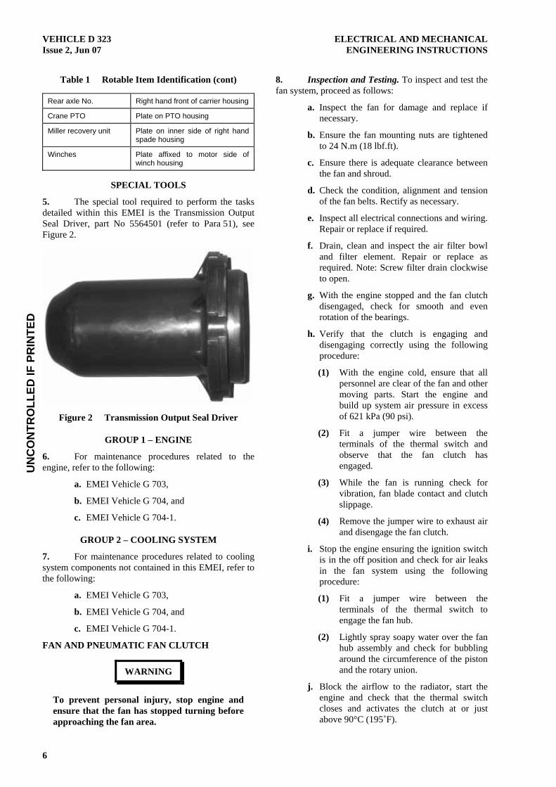
5. The special tool required to perform the tasks detailed within this EMEI is the Transmission Output Seal Driver, part No 5564501 (refer to Para 51), see Figure 2.
Figure 2 Transmission Output Seal Driver
GROUP 1 – ENGINE
6. For maintenance procedures related to the engine, refer to the following:
a. EMEI Vehicle G 703,
b. EMEI Vehicle G 704, and
c. EMEI Vehicle G 704-1.
GROUP 2 – COOLING SYSTEM
7. For maintenance procedures related to cooling system components not contained in this EMEI, refer to the following:
a. EMEI Vehicle G 703,
b. EMEI Vehicle G 704, and
c. EMEI Vehicle G 704-1.
FAN AND PNEUMATIC FAN CLUTCH
WARNING
To prevent personal injury, stop engine and ensure that the fan has stopped turning before approaching the fan area.
8. Inspection and Testing. To inspect and test the fan system, proceed as follows:
a. Inspect the fan for damage and replace if necessary.
b. Ensure the fan mounting nuts are tightened to 24 N.m (18 lbf.ft).
c. Ensure there is adequate clearance between the fan and shroud.
d. Check the condition, alignment and tension of the fan belts. Rectify as necessary.
e. Inspect all electrical connections and wiring. Repair or replace if required.
f. Drain, clean and inspect the air filter bowl and filter element. Repair or replace as required. Note: Screw filter drain clockwise to open.
g. With the engine stopped and the fan clutch disengaged, check for smooth and even rotation of the bearings.
h. Verify that the clutch is engaging and disengaging correctly using the following procedure:
(1) With the engine cold, ensure that all personnel are clear of the fan and other moving parts. Start the engine and build up system air pressure in excess of 621 kPa (90 psi).
(2) Fit a jumper wire between the terminals of the thermal switch and observe that the fan clutch has engaged.
(3) While the fan is running check for vibration, fan blade contact and clutch slippage.
(4) Remove the jumper wire to exhaust air and disengage the fan clutch.
i. Stop the engine ensuring the ignition switch is in the off position and check for air leaks in the fan system using the following procedure:
(1) Fit a jumper wire between the terminals of the thermal switch to engage the fan hub.
(2) Lightly spray soapy water over the fan hub assembly and check for bubbling around the circumference of the piston and the rotary union.
j. Block the airflow to the radiator, start the engine and check that the thermal switch closes and activates the clutch at or just above 90°C (195˚F).
UN
CO
NTR
OLL
ED IF
PR
INTE
DELECTRICAL AND MECHANICAL VEHICLE D 323 ENGINEERING INSTRUCTIONS Issue 2, Jun 07
7
9. Figure 3 illustrates the electrical and pneumatic circuits for the fan clutch.
Figure 3 Fan Clutch Circuits
10. Emergency Operating Procedure. In the event of fan clutch or control system failure that cannot be rectified in the field the following procedure can be used to manually engage the fan clutch. This will enable the vehicle to be operated normally until repairs can be made.
NOTE The vehicle is not to be operated permanently in this condition. Repairs to the fan system must be completed as soon as possible.
a. Disconnect and plug the air line to the fan clutch hub. This is only necessary if air is leaking from the fan clutch.
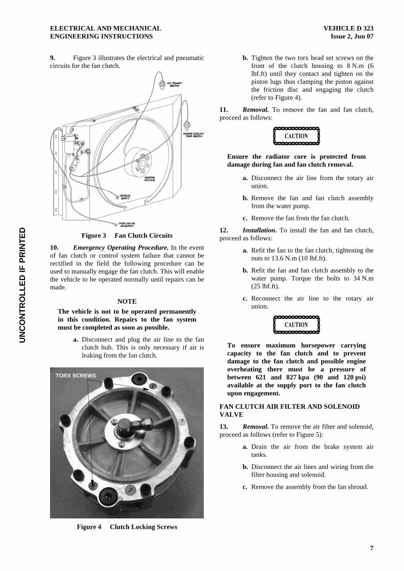
b. Tighten the two torx head set screws on the front of the clutch housing to 8 N.m (6 lbf.ft) until they contact and tighten on the piston lugs thus clamping the piston against the friction disc and engaging the clutch (refer to Figure 4).
11. Removal. To remove the fan and fan clutch, proceed as follows:
Ensure the radiator core is protected from damage during fan and fan clutch removal.
a. Disconnect the air line from the rotary air union.
b. Remove the fan and fan clutch assembly from the water pump.
c. Remove the fan from the fan clutch.
12. Installation. To install the fan and fan clutch, proceed as follows:
a. Refit the fan to the fan clutch, tightening the nuts to 13.6 N.m (10 lbf.ft).
b. Refit the fan and fan clutch assembly to the water pump. Torque the bolts to 34 N.m (25 lbf.ft).
c. Reconnect the air line to the rotary air union.
To ensure maximum horsepower carrying capacity to the fan clutch and to prevent damage to the fan clutch and possible engine overheating there must be a pressure of between 621 and 827 kpa (90 and 120 psi) available at the supply port to the fan clutch upon engagement.
FAN CLUTCH AIR FILTER AND SOLENOID VALVE
13. Removal. To remove the air filter and solenoid, proceed as follows (refer to Figure 5):
a. Drain the air from the brake system air tanks.
b. Disconnect the air lines and wiring from the filter housing and solenoid.
c. Remove the assembly from the fan shroud.
Figure 4 Clutch Locking Screws
TORX SCREWS

UN
CO
NTR
OLL
ED IF
PR
INTE
DVEHICLE D 323 ELECTRICAL AND MECHANICAL Issue 2, Jun 07 ENGINEERING INSTRUCTIONS
8
Figure 5 Horton Air Filter and Solenoid Valve
14. Disassembly. To disassemble the air filter and solenoid, proceed as follows (refer to Figure 6):
a. Unscrew the air filter from the solenoid.
b. Remove the fittings from either unit if necessary.
c. Remove the bowl and filter element from the filter head.
Figure 6 Fan Clutch Air Filter and Solenoid
15. Cleaning and Inspection. To clean and inspect the air filter and solenoid, proceed as follows:
a. Clean the air cleaner assembly in clean solvent and dry thoroughly and wipe the solenoid valve with a damp cloth.
b. Check both items for damage and replace as necessary. Correct operation of the solenoid valve should have been assessed during the system inspection process at Para 8. If not, test the solenoid by connecting the black
earth wire to ground and the green power wire to 24 V dc.
16. Assembly. Apply thread sealant to the threads of any removed air fittings and assemble the air filter and solenoid in reverse order to disassembly.
17. Installation. Install the air filter and solenoid assembly in reverse order to removal, refit the air lines and check for air leaks in accordance with Para 8.
FAN CLUTCH THERMAL SWITCH
WARNING
To prevent burns from hot coolant, ensure that the coolant is sufficiently cool and the pressure has been relieved prior to removal of the thermal switch.
18. Figure 7 shows the location of the fan clutch thermal switch. The switch is a normally open type set to close at 90°C (195˚F).
Figure 7 Fan Clutch Thermal Switch
RADIATOR
19. Removal and installation of the radiator is to be conducted in accordance with EMEI Vehicle G 703. Prior to removal of the radiator disconnect the fan clutch air lines and wiring (refer to Para 13). On completion of installation, reconnect the fan clutch (refer to Para 17).
FAULT FINDING
20. Table 3 lists fault finding procedures for the Horton fan clutch.
DRAIN VALVE
AIR FILTER
SOLENOID VALVE
FILTER ELEMENT

UN
CO
NTR
OLL
ED IF
PR
INTE
DELECTRICAL AND MECHANICAL VEHICLE D 323 ENGINEERING INSTRUCTIONS Issue 2, Jun 07
9
Table 2 Fan Clutch Fault Finding
Symptom Probable Cause Action
1. Fan clutch fails to engage Electrical Fault:
a. Broken circuit (normally open system)
Check electrical circuit (see Figure 3).
b. Improperly wired circuit Check that wiring is in accordance to circuit diagram.
c. Incorrect thermal switch fitted Check that thermal switch is Normally Open and rated at 90˚C (195˚F).
d. Faulty solenoid valve Replace the solenoid valve.
Pneumatic Fault:
a. Air leaks in fan clutch Install new ‘O’ rings.
b. Restricted air supply to fan clutch Check air lines and fittings for leaks and/or restrictions. Ensure that the supply air pressure is at least 621 to 827 kPa (90 to 120 psi).
2. Fan clutch fails to disengage Electrical Fault:
a. Improperly wired circuit Check that wiring is in accordance with circuit diagram (see Figure 3).
b. Faulty thermal switch Replace thermal switch (refer to Figure 7).
Pneumatic Fault:
a. Air line restricted, not allowing air to exhaust from the fan clutch
Check the air line between the fan clutch and the solenoid valve for restrictions and/or obstructions.
b. Faulty solenoid valve Replace the solenoid valve.
3. Fan clutch engaged, engine running hot
a. Restriction in front of radiator Check for obstructions or dirt blocking air flow through radiator core.
b. Cooling system fault Refer to the fault finding section of EMEI Vehicle G 703 Group 1.
4. Fan clutch cycles frequently Electrical Fault:
a. Poor earth wire connection Check electrical connections.
b. Improper temperature control settings
Check temperature setting of all controls. Thermal switch rating should be 90°C (195˚F) allowing the clutch to engage approximately 5 to 6˚C (10°F) above the fully open temperature of the thermostat.
c. A/C pressure switch setting too low Check the A/C pressure switch.
d. Restriction in front of radiator Check for obstructions or dirt blocking air flow through radiator core.
e. Faulty thermal switch Replace thermal switch (refer to Figure 7).
f. Faulty air temperature switch Replace air temperature switch.
Pneumatic Fault:
a. Air line restricted, not allowing air to exhaust from the fan clutch
Check the air line between the fan clutch and the solenoid valve for restrictions and/or obstructions.
b. Solenoid valve not exhausting Check for a blocked exhaust port on the solenoid valve. Clean or replace the solenoid valve.
UN
CO
NTR
OLL
ED IF
PR
INTE
DVEHICLE D 323 ELECTRICAL AND MECHANICAL Issue 2, Jun 07 ENGINEERING INSTRUCTIONS
10
GROUP 3 – EXHAUST SYSTEM
21. For maintenance procedures related to the exhaust system, refer to the following:
a. EMEI Vehicle G 703,
b. EMEI Vehicle G 704, and
c. EMEI Vehicle G 704-1.
GROUP 4 – FUEL SYSTEM
22. For maintenance procedures related to fuel system components not contained in this EMEI, refer to the following:
a. EMEI Vehicle G 703,
b. EMEI Vehicle G 704, and
c. EMEI Vehicle G 704-1.
HAND THROTTLE
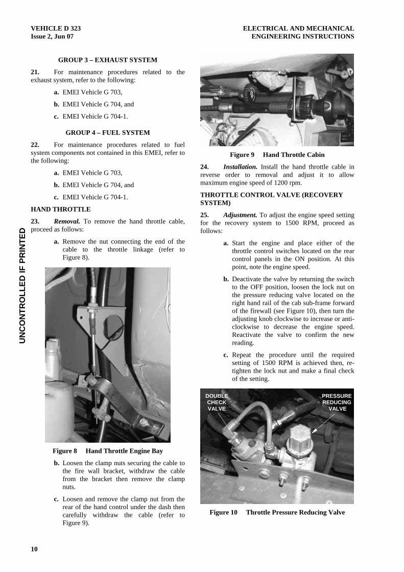
23. Removal. To remove the hand throttle cable, proceed as follows:
a. Remove the nut connecting the end of the cable to the throttle linkage (refer to Figure 8).
Figure 8 Hand Throttle Engine Bay
b. Loosen the clamp nuts securing the cable to the fire wall bracket, withdraw the cable from the bracket then remove the clamp nuts.
c. Loosen and remove the clamp nut from the rear of the hand control under the dash then carefully withdraw the cable (refer to Figure 9).
Figure 9 Hand Throttle Cabin
24. Installation. Install the hand throttle cable in reverse order to removal and adjust it to allow maximum engine speed of 1200 rpm.
THROTTLE CONTROL VALVE (RECOVERY SYSTEM)
25. Adjustment. To adjust the engine speed setting for the recovery system to 1500 RPM, proceed as follows:
a. Start the engine and place either of the throttle control switches located on the rear control panels in the ON position. At this point, note the engine speed.
b. Deactivate the valve by returning the switch to the OFF position, loosen the lock nut on the pressure reducing valve located on the right hand rail of the cab sub-frame forward of the firewall (see Figure 10), then turn the adjusting knob clockwise to increase or anti-clockwise to decrease the engine speed. Reactivate the valve to confirm the new reading.
c. Repeat the procedure until the required setting of 1500 RPM is achieved then, re-tighten the lock nut and make a final check of the setting.
Figure 10 Throttle Pressure Reducing Valve
PRESSURE REDUCING
VALVE
DOUBLE CHECK VALVE
UN
CO
NTR
OLL
ED IF
PR
INTE
DELECTRICAL AND MECHANICAL VEHICLE D 323 ENGINEERING INSTRUCTIONS Issue 2, Jun 07
11
26. Removal. To remove the pressure reducing and/or double check valve, proceed as follows:
a. Drain the air from the brake system air tanks.
b. Tag and disconnect the air lines from the valve/s to be removed.
c. Remove the valve/s from the mounting bracket.
27. Installation. To install the pressure reducing and/or double check valve, proceed as follows:
a. Refit the valve/s to the mounting bracket and reconnect the air lines. Refer to Figure 51 for the pneumatic diagram.
b. Start the truck to charge the air system.
c. Inspect the system for leaks then adjust the pressure reducing valve in accordance with Para 25.
AIR FILTERS
28. Removal. To remove the filter elements, proceed as follows:
a. Remove the air intake and cover assembly from the top of the body assembly.
b. Withdraw the filter element from the body.
29. Cleaning and Inspection. To inspect the filter element and air cleaner components, proceed as follows:
a. Clean out the inside of the body and the dust cup using a clean dry cloth.
b. Clean the air intake assembly using warm soapy water if necessary and dry thoroughly.
c. Inspect the condition of the filter element and clean or replace as necessary.
d. Inspect the condition of the cover seal, dust cup and flexible duct. Replace as necessary.
30. Installation. To install the filter elements, proceed as follows:
a. Install the filter element into the body.
b. Refit the air intake and cover assembly, fit and tighten the securing bolts.
SPEED LIMITER
Adjustment of the speed limiter is only to be performed by mack trucks (aust) or an authorised agent.
31. Testing. To test the speed limiter, drive vehicle on straight flat road with at least 100 km speed limit, slowly increasing speed. Speed limiter should activate at approximately 100 to 102 kph.
Solenoid Valve
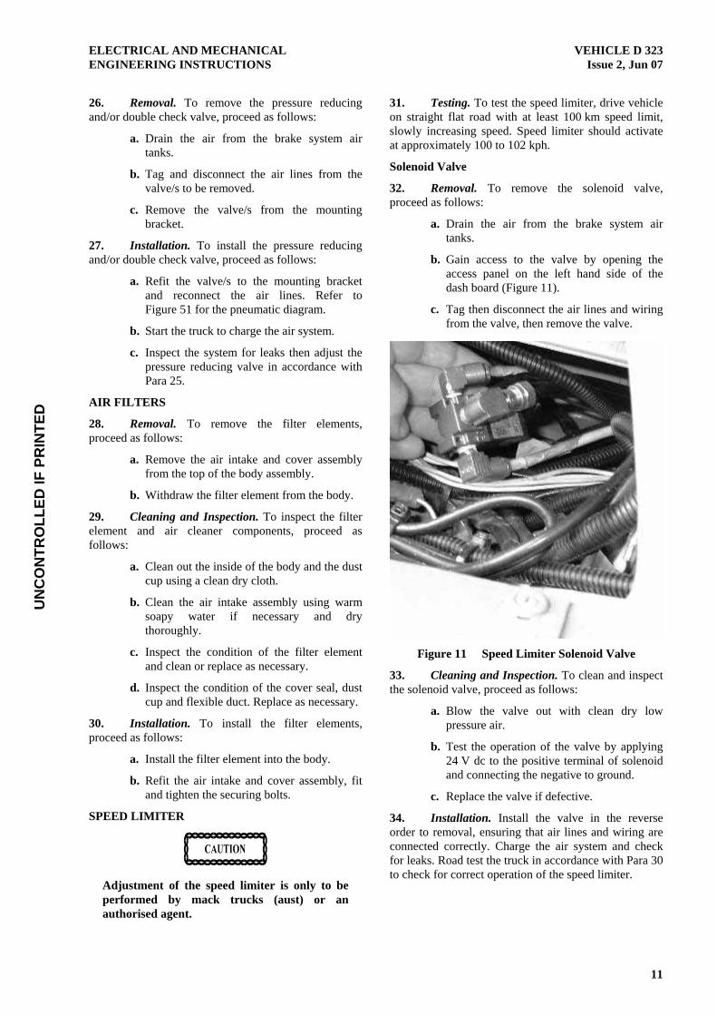
32. Removal. To remove the solenoid valve, proceed as follows:
a. Drain the air from the brake system air tanks.
b. Gain access to the valve by opening the access panel on the left hand side of the dash board (Figure 11).
c. Tag then disconnect the air lines and wiring from the valve, then remove the valve.
Figure 11 Speed Limiter Solenoid Valve
33. Cleaning and Inspection. To clean and inspect the solenoid valve, proceed as follows:
a. Blow the valve out with clean dry low pressure air.
b. Test the operation of the valve by applying 24 V dc to the positive terminal of solenoid and connecting the negative to ground.
c. Replace the valve if defective.
34. Installation. Install the valve in the reverse order to removal, ensuring that air lines and wiring are connected correctly. Charge the air system and check for leaks. Road test the truck in accordance with Para 30 to check for correct operation of the speed limiter.
UN
CO
NTR
OLL
ED IF
PR
INTE
DVEHICLE D 323 ELECTRICAL AND MECHANICAL Issue 2, Jun 07 ENGINEERING INSTRUCTIONS
12
GROUP 5 – CLUTCH
CLUTCH PEDAL AND CABLE
35. For maintenance procedures related to the clutch pedal and cable, refer to the following:
a. EMEI Vehicle G 703, and
b. EMEI Vehicle G 704.
SOLO CLUTCH MAINTENANCE
36. The 15½ inch Solo clutch fitted to this truck is self adjusting and should not require in-service adjustment. Clutch inspection, maintenance and replacement are to be carried out in accordance with the procedures detailed within this section. Clutch replacement should only be conducted in the following circumstances:
a. The wear tab is in the REPLACE position indicating that the clutch has worn out.
b. Loose parts are found in the clutch housing.
c. There have been repeated occurrences of over adjustment.
d. Drive line and other clutch related faults as detailed in Table 4 have been excluded.
e. Completing the clutch set-up verification procedure detailed in EMEI Vehicle D 324-1 does not rectify the fault.
Do not use the wear indicator tab to adjust or attempt to adjust the clutch unless instructed by a procedure detailed within this emei or emei vehicle d 324-1.
37. Clutch Linkage Adjustment. To adjust the clutch linkage, proceed as follows:
a. Remove the inspection plate from the base of the clutch housing and have someone fully depress the clutch pedal and hold it down.
b. Slide the wear indicator tab to the left until it reaches the NEW position.
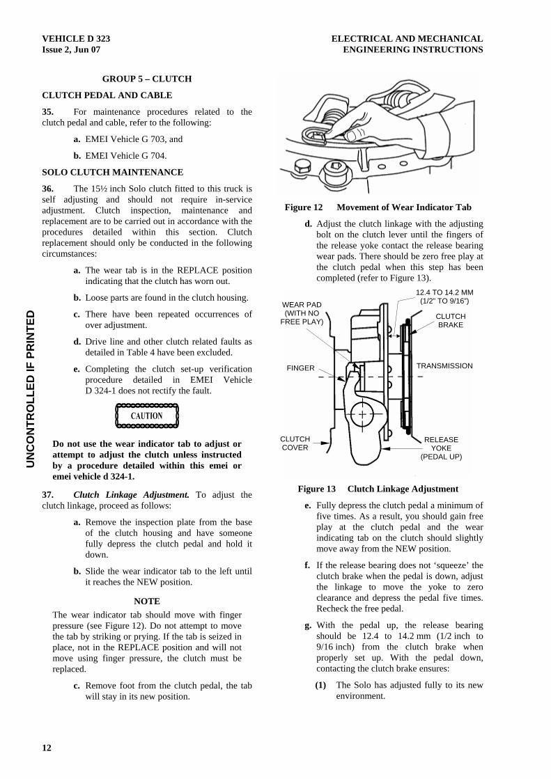
NOTE The wear indicator tab should move with finger pressure (see Figure 12). Do not attempt to move the tab by striking or prying. If the tab is seized in place, not in the REPLACE position and will not move using finger pressure, the clutch must be replaced.
c. Remove foot from the clutch pedal, the tab will stay in its new position.
Figure 12 Movement of Wear Indicator Tab
d. Adjust the clutch linkage with the adjusting bolt on the clutch lever until the fingers of the release yoke contact the release bearing wear pads. There should be zero free play at the clutch pedal when this step has been completed (refer to Figure 13).
Figure 13 Clutch Linkage Adjustment
e. Fully depress the clutch pedal a minimum of five times. As a result, you should gain free play at the clutch pedal and the wear indicating tab on the clutch should slightly move away from the NEW position.
f. If the release bearing does not ‘squeeze’ the clutch brake when the pedal is down, adjust the linkage to move the yoke to zero clearance and depress the pedal five times. Recheck the free pedal.
g. With the pedal up, the release bearing should be 12.4 to 14.2 mm (1/2 inch to 9/16 inch) from the clutch brake when properly set up. With the pedal down, contacting the clutch brake ensures:
(1) The Solo has adjusted fully to its new environment.
CLUTCH COVER
FINGER
WEAR PAD (WITH NO
FREE PLAY)
TRANSMISSION
CLUTCH BRAKE
RELEASE YOKE
(PEDAL UP)
12.4 TO 14.2 MM (1/2” TO 9/16”)
UN
CO
NTR
OLL
ED IF
PR
INTE
DELECTRICAL AND MECHANICAL VEHICLE D 323 ENGINEERING INSTRUCTIONS Issue 2, Jun 07
13
(2) The linkage is capable of pulling the bearing far enough to obtain ‘clutch brake squeeze’.
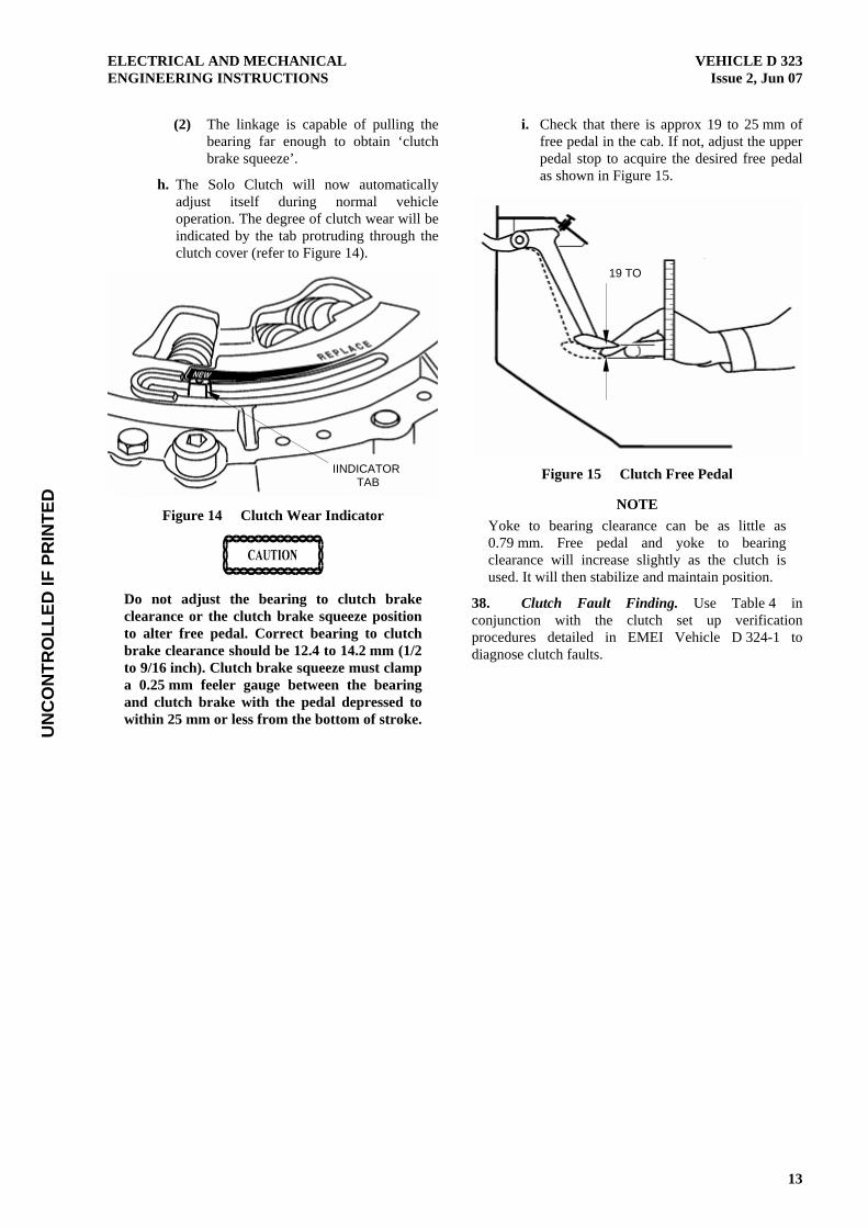
h. The Solo Clutch will now automatically adjust itself during normal vehicle operation. The degree of clutch wear will be indicated by the tab protruding through the clutch cover (refer to Figure 14).
Figure 14 Clutch Wear Indicator
Do not adjust the bearing to clutch brake clearance or the clutch brake squeeze position to alter free pedal. Correct bearing to clutch brake clearance should be 12.4 to 14.2 mm (1/2 to 9/16 inch). Clutch brake squeeze must clamp a 0.25 mm feeler gauge between the bearing and clutch brake with the pedal depressed to within 25 mm or less from the bottom of stroke.
i. Check that there is approx 19 to 25 mm of free pedal in the cab. If not, adjust the upper pedal stop to acquire the desired free pedal as shown in Figure 15.
Figure 15 Clutch Free Pedal
NOTE Yoke to bearing clearance can be as little as 0.79 mm. Free pedal and yoke to bearing clearance will increase slightly as the clutch is used. It will then stabilize and maintain position.
38. Clutch Fault Finding. Use Table 4 in conjunction with the clutch set up verification procedures detailed in EMEI Vehicle D 324-1 to diagnose clutch faults.
IINDICATOR TAB
19 TO

UN
CO
NTR
OLL
ED IF
PR
INTE
DVEHICLE D 323 ELECTRICAL AND MECHANICAL Issue 2, Jun 07 ENGINEERING INSTRUCTIONS
14
Table 3 Clutch Fault Finding
Symptom Probable Cause Action
Poor Release Pressure plate not fully retracting Verify that the release bearing travel is 12.4 to 14.2 mm (1/2 to 9/16 inch). Determine if the lever nose is out of the groove in the release sleeve retainer. If it is, be sure to reinstall (refer to Para 37).
Excessive release bearing travel, causing lever to contact pressure plate (in excess of 16 mm)
Adjust to 12.4 to 14.2 mm (1/2 to 9/16 inch) release bearing travel (refer to Para 37).
Incorrect pedal height Adjust the clutch linkages in accordance with Para 37 to obtain the following:
1. 12.4 to 14.2 mm (1/2 to 9/16 inch) release bearing travel,
2. 3 mm free travel at the release yoke, and
3. 12.5 to 25.5 mm clutch brake squeeze.
No clutch brake squeeze Adjust the clutch linkages in accordance with Para 37.
Damaged bushing in the release bearing sleeve assembly
Replace the clutch in accordance with EMEI Vehicle D 324-1.
Cover assembly not properly seated into pilot of fly wheel
Reseat into flywheel. Use crisscross pattern when tightening mounting bolts (refer to EMEI Vehicle D 324-1).
The intermediate and/or pressure plate are either cracked or broken. Possible causes of this damage are as follows:
1. Holding vehicle on hill with the clutch
2. Overload
3. Starting off in the wrong gear
4. Wrong cover assembly installed allowing clutch to slip (misapplication)
5. Intermediate plate hanging up, allowing clutch to slip
Replace the clutch in accordance with EMEI Vehicle D 324-1.
Release sleeve bushing is contacting the transmission input shaft due to a side loading condition. This condition can be the result of one or more of the following items:
1. Cross shafts protruding through the release yoke
Check for protruding cross shafts.
2. Finger(s) of release yoke are bent Install a new release yoke (refer to EMEI Vehicle G 704).
3. Clutch cover is not mounted concentric and/ or not properly seated into the flywheel pilot
When mounting clutch cover to the flywheel, always tighten the mounting bolts to their proper torque using the crisscross pattern (see EMEI Vehicle D 324-1).
4. Misalignment between the transmission bell housing and engine housing
Inspect the mating surfaces of the clutch and engine flywheel housing and replace if worn or damaged.
5. Loose transmission mounting bolts Tighten bolts to 102 N.m (75 lbf.ft).
6. Improper setup of linkage Thoroughly examine the linkage to determine if it can be contributing to a side loading condition.

UN
CO
NTR
OLL
ED IF
PR
INTE
DELECTRICAL AND MECHANICAL VEHICLE D 323 ENGINEERING INSTRUCTIONS Issue 2, Jun 07
15
Table 3 Clutch Fault Finding
Symptom Probable Cause Action
Driven disc distorted or warped Damage to driven discs can be caused by poor installation methods. Do not force transmission drive gear into disc hubs. This will distort or bend driven disc causing poor release. Also, do not allow transmission to hang unsupported. Replace any distorted or warped discs in accordance with EMEI Vehicle D 324-1.
Disc(s) installed backwards or front and rear discs were switched with each other
Replace discs in accordance with EMEI Vehicle D 324-1 and inspect the clutch cover for any damage. Replace if necessary.
Spline worn on main drive gear of transmission Replace drive gear and check driven disc hubs for excessive wear. If worn, replace disc. Check flywheel housing alignment of engine and transmission. Make sure driven discs slide freely on drive gear splines. Refer to EMEI Vehicle D 324-1.
Flywheel spigot bearing fits either too tight or too loose in the flywheel and/or end of input shaft
Check spigot bearing for correct fit.
Damaged or dry (rough) spigot bearing Replace with new bearing.
Failure to set the positive separator pins during clutch installation
It is important to note that the procedure for setting the positive separator pins can be performed while the transmission is installed. The steps are as follows:
1. Remove the transmission inspection hole cover.
2. Rotate the clutch cover until one of the holes (for setting the pins) is at the 6 o’clock position.
3. Using a 6 mm diameter flat nose punch, lightly tap the separator pin to verify that it is seated against the flywheel.
4. Repeat steps 2 and 3 for the remaining three separator pins.
5. Reinstall the transmission inspection hole cover.
Bent/damaged positive separator pin(s) 1. Use the proper tool when setting the pins.
2. Take great care when handling the intermediate plate.
The release yoke bridge is contacting the cover assembly at the full release position (clutch pedal to floor). This may be due to any of the following:
1. Worn clutch brake, broken or missing clutch plate
2. Worn transmission bearing retainer cap
3. Excessive wear on release bearing wear pads and/or the fingers of the release yoke
4. Improper linkage set up
Inspect the possible faults and correct as required.
Damaged or non-functioning clutch brake Install new clutch brake.
Rust preventative, ie never seize, grease, etc. on transmission input drive gear
Drive gear should be clean and dry before installing discs.

UN
CO
NTR
OLL
ED IF
PR
INTE
DVEHICLE D 323 ELECTRICAL AND MECHANICAL Issue 2, Jun 07 ENGINEERING INSTRUCTIONS
16
Table 3 Clutch Fault Finding
Symptom Probable Cause Action
Incorrect use of clutch brake when shifting into 1st gear. Sometimes when applying the clutch with the vehicle on a grade, the transmission gears can become locked together due to the applied torque, making it difficult to shift into and out of gear.
Let up on the clutch pedal a few inches in order to disengage the clutch brake. Doing so will allow the input shaft to roll-over slightly, eliminating the locking condition of the transmission gears and allow for effort less shifting.
Grease or oil on facings Replace discs in accordance with EMEI Vehicle D 324-1.
Foreign material on the internal workings of the clutch cover (dirt, chaff, salt, etc.)
Remove foreign material. Ensure that the transmission inspection hole cover is reinstalled to minimize future problems.
Noisy/Rattling Excessive flywheel runout Measure flywheel runout in accordance with EMEI Vehicle D 324-1.
Corrosion of disc hubs to transmission input shaft Clean the mating parts to ensure that the discs slide freely over input shaft.
Engine idling too fast Adjust engine idling speed to between 525 and 575 rpm.
Clutch release bearing is dry or damaged Lubricate the bearing. If the noise persists, install a new clutch cover (the release bearing will be included with the cover).
Flywheel spigot bearing is dry or damaged Replace flywheel spigot bearing.
Fingers of release yoke hitting clutch cover. This may be due to any of the following:
1. Broken or incorrectly installed linkage system allowing the loose yoke to contact the clutch cover
2. Incorrect clutch adjustment
Inspect and correct as required.
Failure to use the transmission inspection hole cover
Re-install the cover.
Worn sleeve bushing Investigate for any side loading conditions on the release bearing housing. Determine the cause, being sure to correct before installing the new clutch.
Linkage system is frozen, improperly lubricated, worn excessively, has missing parts (washers, etc.), or the linkage itself is rattling excessively
Clean, lubricate and reassemble or replace missing/ worn parts.
Idle gear rattle coming from the transmission Check the engine for the correct idle speed.
Clutch is loose on flywheel Install a new clutch assembly in accordance with EMEI Vehicle D 324-1 and eight new mounting bolts.
Vibrating Clutch Loose flywheel Re-tighten flywheel mounting bolts to the proper specifications (refer to EMEI Vehicle G 704).
Worn universal joints Replace worn parts (refer to EMEI Vehicle G 703).
Improper phasing of driveshaft Investigate for correct yoke phasing (refer to EMEI Vehicle G 703).
Driveshaft is not balanced Balance and straighten driveshaft. Also, ensure that no balance weights have come off the driveshaft.
Flywheel is not balanced Balance the flywheel.
Pilot area of the clutch is not completely seated into flywheel
Ensure that no dirt, burrs, etc. are preventing the cover from completely seating into the flywheel mounting surface.

UN
CO
NTR
OLL
ED IF
PR
INTE
DELECTRICAL AND MECHANICAL VEHICLE D 323 ENGINEERING INSTRUCTIONS Issue 2, Jun 07
17
Table 3 Clutch Fault Finding
Symptom Probable Cause Action
Failure to tighten the clutch cover mounting bolts, using a crisscross sequence, can cause an out-of-balance condition. Loose mounting bolts can also induce this condition.
Ensure bolts are tightened in accordance with EMEI Vehicle D 324-1.
Damaged, loose, or worn out engine mounts Replace any damaged/worn parts. Retighten all loose bolts to proper specifications. Refer to EMEI Vehicle G 703.
Misfiring of engine Refer to EMEI Vehicle G 703 and EMEI Vehicle D 324-2.
Excessive flywheel runout Refer to EMEI Vehicle D 324-1.
Clutch is loose on flywheel Install a new clutch assembly in accordance with EMEI Vehicle D 324-1 and eight new mounting bolts.
Insufficient amount of free travel. When the clutch was initially installed, the linkage was not adjusted to obtain a full 3 mm free travel.
After first adjusting the clutch for 12.4 to 14.2 mm (1/2 to 9/16 inch) release bearing travel, adjust the linkage to obtain a 3 mm free travel in accordance with Para 37 (distance between the release yoke fingers and the release bearing wear pads).
Starting out in too high a gear may lead to premature clutch wear
Start the vehicle moving in an appropriate gear (refer to Technical Manual User Handbook).
Worn cross shafts and/or linkage system Investigate entire linkage system to determine if it is binding or operating sporadically and/or worn excessively.
Clutch discs worn down to rivets Replace the clutch in accordance with EMEI Vehicle D 324-1.
Riding of clutch pedal, causing premature wear Do not use the clutch pedal as a foot rest. Driver instruction required.
Holding the vehicle on an incline by using the slipping clutch as a brake. Doing this can cause premature wear.
Refrain from using the clutch as a brake. Driver instruction required.
Sporadic changes in the amount of free play due to excessive crankshaft end play
Engine fault, refer to EMEI Vehicle G 703.
Too Much Free Play on Clutch
Failure to install a clutch brake when one is required. This condition will cause the Solo’s release bearing to adjust closer than normal to the transmission’s bearing retainer cap and will also cause the wear tab to move toward the half worn position.
Reset the wear tab to the new position. Install a new clutch brake. Readjust the Solo using the normal adjusting procedures (refer to Para 37).
Solo Clutch has over adjusted (release bearing is less than 12.4 mm (1/2 inch) from the transmission)
Reset the wear tab to the new position. Readjust the Solo using the normal adjusting procedures (refer to Para 37).
Failure to properly set-up the clutch linkage Reset the linkage to obtain a free travel (at the yoke) range of 1.5 to 3 mm (refer to Para 37).
Nothing is wrong. It is normal for the free play to increase during the Solo’s ‘Breaking in’ period
None is required, but if the additional free play is objectionable, you may readjust the linkage until you have 1.5 to 3 mm of free travel at the release yoke (refer to Para 37).
Clutch Slippage No free pedal Re-adjust clutch (refer to Para 37).
Release mechanism binding Free up mechanism and linkage, check clutch adjustment. Refer to adjustment instructions found in Eaton’s Installation Instructions.
Failure to remove shipping/resetting bolts Remove shipping/resetting bolts.
Grease or oil on facings Replace discs in accordance with EMEI Vehicle D 324-1.
Driver riding clutch pedal Refrain from riding the clutch pedal.

UN
CO
NTR
OLL
ED IF
PR
INTE
DVEHICLE D 323 ELECTRICAL AND MECHANICAL Issue 2, Jun 07 ENGINEERING INSTRUCTIONS
18
Table 3 Clutch Fault Finding
Symptom Probable Cause Action
Input shaft spline wear Replace the input shaft (refer to EMEI Vehicle D 324-2).
Chattering, Erratic Engagement, Clutch Grabs
Clutch is worn out, the driven disc assembly(s) have worn down to the facing rivets
Replace the clutch in accordance with EMEI Vehicle D 324-1.
The linkage system is not operating freely, it is binding and/or worn excessively
Replace all worn parts (refer to EMEI Vehicle D 324-1 and EMEI Vehicle G 704).
Grease or oil on facings Replace discs in accordance with EMEI Vehicle D 324-1.
Loose engine mounts Tighten.
The fingers of the release yoke and/or the wear pads on the release bearing are worn excessively
Replace all worn components (refer to EMEI Vehicle D 324-1 and EMEI Vehicle G 704).
UN
CO
NTR
OLL
ED IF
PR
INTE
DELECTRICAL AND MECHANICAL VEHICLE D 323 ENGINEERING INSTRUCTIONS Issue 2, Jun 07
19
GROUP 6 – TRANSMISSION
WARNING
BEFORE STARTING ANY DRIVELINE MAINTENANCE PROCEDURES ON THIS VEHICLE, APPLY THE PARKING BRAKES, PLACE THE TRANSMISSION IN NEUTRAL, AND CHOCK THE WHEELS.
TO AVOID TRANSMISSION DAMAGE WHEN TOWING THIS VEHICLE, PLACE THE TRANSMISSION IN NEUTRAL AND REMOVE ALL FOUR REAR AXLES. THIS VEHICLE MUST BE TRANSPORTED BY TRAILER IF THE NATURE OF DAMAGE PREVENTS FRONT LIFT TOWING.
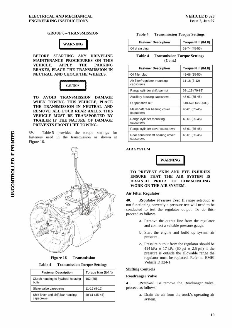
39. Table 5 provides the torque settings for fasteners used in the transmission as shown in Figure 16.
Figure 16 Transmission
Table 4 Transmission Torque Settings
Fastener Description Torque N.m (lbf.ft)
Clutch housing to flywheel housing bolts
102 (75)
Slave valve capscrews 11-16 (8-12)
Shift lever and shift bar housing capscrews
48-61 (35-45)
Table 4 Transmission Torque Settings
Fastener Description Torque N.m (lbf.ft)
Oil drain plug 61-74 (45-55)
Table 4 Transmission Torque Settings (Cont.)
Fastener Description Torque N.m (lbf.ft)
Oil filler plug 48-68 (35-50)
Air filter/regulator mounting capscrews
11-16 (8-12)
Range cylinder shift bar nut 95-115 (70-85)
Auxiliary housing capscrews 48-61 (35-45)
Output shaft nut 610-678 (450-500)
Mainshaft rear bearing cover capscrews
48-61 (35-45)
Range cylinder mounting capscrews
48-61 (35-45)
Range cylinder cover capscrews 48-61 (35-45)
Rear countershaft bearing cover capscrews
48-61 (35-45)
AIR SYSTEM
WARNING
TO PREVENT SKIN AND EYE INJURIES ENSURE THAT THE AIR SYSTEM IS DRAINED PRIOR TO COMMENCING WORK ON THE AIR SYSTEM.
Air Filter Regulator
40. Regulator Pressure Test. If range selection is not functioning correctly a pressure test will need to be conducted to test the regulator output. To do this, proceed as follows:
a. Remove the output line from the regulator and connect a suitable pressure gauge.
b. Start the engine and build up system air pressure.
c. Pressure output from the regulator should be 414 kPa ± 17 kPa (60 psi ± 2.5 psi) if the pressure is outside the allowable range the regulator must be replaced. Refer to EMEI Vehicle D 324-1.
Shifting Controls
Roadranger Valve
41. Removal. To remove the Roadranger valve, proceed as follows:
a. Drain the air from the truck’s operating air system.

UN
CO
NTR
OLL
ED IF
PR
INTE
DVEHICLE D 323 ELECTRICAL AND MECHANICAL Issue 2, Jun 07 ENGINEERING INSTRUCTIONS
20
b. Remove two screws holding the bottom cover onto the valve then slide the cover down the lever to expose the air line fittings.
c. Disconnect the air lines from the fittings then loosen the lock nut and unscrew the Roadranger valve from the gear shift lever.
42. Installation. To install the Roadranger valve, proceed as follows:
a. Refit the Roadranger valve onto the gear shift lever and tighten the jam nut.
b. Reconnect the air lines and refit the bottom cover (refer to Figure 17).
Figure 17 Transmission Air Lines
GEAR SHIFT LEVER HOUSING
Inspection Points
43. The following are the inspection points for the gear shift lever housing:
a. Check spring tension on shift lever. Replace tension spring and washer if lever moves too freely.
b. If housing is disassembled, check spade pin and corresponding slot in lever for wear. Replace both parts if extremely worn.
44. Removal. To remove the gear shift lever housing, proceed as follows:
a. Remove the Roadranger valve if not previously removed in accordance with Para 41.
b. Remove the four retaining cap screws and jar the housing lightly to break the gasket seal. Remove the shift lever housing and gasket from the shift bar housing.
45. Disassembly. To disassemble the gear shift lever housing, proceed as follows (refer to Figure 18):
a. Remove the main gear shift lever from the lever stub if not previously removed.
b. Remove the boot from the gear shift lever and secure the assembly in a vice with bottom of the housing facing up.
c. Using a large screwdriver, twist between the tension spring and housing to force the spring from under the retaining lugs gradually removing one coil at a time.
d. Remove the tension spring, spring seat and stub lever from the housing.
e. Remove the spade pin, retainer and ‘O’ ring from the bore of the housing.
Figure 18 Gear Shift Lever Housing
SUPPLY
LO RANGE
END PORT
SUPPLY HI RANGE
SUPPLY FROM
VEHICLE
P
S
L
H
L
H SPADE
SPRING
‘O’ RING
STUB
‘O’ RING RETAINER

UN
CO
NTR
OLL
ED IF
PR
INTE
DELECTRICAL AND MECHANICAL VEHICLE D 323 ENGINEERING INSTRUCTIONS Issue 2, Jun 07
21
46. Cleaning and Inspection. To clean and inspect the shift lever housing, proceed as follows:
a. Clean all metal components with cleaning spirit and blow dry with low pressure air.
b. Visually inspect all components for damage and wear, paying particular attention to the spade pin and slot in the stub lever ball. Replace parts as necessary.
47. Assembly. To assemble the shift lever housing, proceed as follows:
a. With the gear shift lever housing secured in a vice as during disassembly, install the spade pin and ‘O’ ring in the bore of housing.
b. Insert the stub lever into the housing ensuring that the spade pin is aligned with the slot in the ball then install the tension spring washer over the ball, dished side up.
c. Using a large screwdriver, install the tension spring under the retaining lugs in the top of the housing, seating one coil at a time.
d. Remove the assembly from the vice and install the rubber boot over the top of the stub lever.
48. Installation. To install the shift lever housing, proceed as follows:
NOTE Prior to refitting the shift lever housing, ensure that the detent balls and springs are in place in the shift bar housing.
a. Ensure the shift block and yoke notches are aligned in the neutral position then fit a new gasket to the top of the shift bar housing. Refit the shift lever housing ensuring that the stub lever engages with the yoke notches.
b. Install the four retaining screws and tighten to 48 to 61 N.m (35 to 45 lbf.ft).
c. Refit the Roadranger valve in accordance with Para 42.
AUXILIARY SECTION
Output Seal and Drive Yoke
49. Removal. To remove the output seal and drive yoke, proceed as follows:
a. Disconnect the propeller shaft from the drive yoke (refer to EMEI Vehicle G 703).
b. Engaging 1st gear, low range to prevent the output yoke from turning then loosen and remove the nut from output shaft.
c. Pull the yoke straight off the rear of the output shaft then remove the speedometer drive rotor and spacer from the output shaft.
d. Remove the oil slinger from the yoke and pull the oil seal out of the bearing cover.
50. Cleaning and Inspection. To clean and inspect the drive yoke and output shaft, proceed as follows:
a. Clean all components using clean solvent and dry thoroughly.
b. Inspect the splines on the output shaft and drive yoke for wear and damage.
DO NOT USE EMERY CLOTH OR ANY OTHER ABRASIVE MEDIUM TO CLEAN THE SEALING SURFACE OF THE DRIVE YOKE. DOING SO MAY DAMAGE THE SURFACE FINISH CAUSING PREMATURE SEAL FAILURE.
c. Inspect the sealing surface of the drive yoke for wear or scoring.
d. Replace worn or damaged components as necessary.
51. Installation. To install the output seal, proceed as follows (refer to Figure 19):
a. Refit the spacer and speedometer drive rotor onto the output shaft.
b. Install a new output seal into the bearing cover using the output seal driver (refer to Para 5) and fit the new oil slinger onto the drive yoke.
c. Refit the drive yoke and nyloc nut and tension to between 610 to 678 N.m (450 to 500 lbf.ft).
d. Refit the propeller shaft in accordance with EMEI Vehicle G 703.

UN
CO
NTR
OLL
ED IF
PR
INTE
DVEHICLE D 323 ELECTRICAL AND MECHANICAL Issue 2, Jun 07 ENGINEERING INSTRUCTIONS
22
Figure 19 Rear Bearing Cover and Drive Yoke
PREVENTATIVE MAINTENANCE
In Vehicle Checks
52. The following checks can be conducted without any removal or disassembly of components:
a. Air System and Connections. Check for leaks, worn air lines, loose connections and cap screws.
b. Cap Screws and Gaskets:
(1) Check the security of all cap screws which could cause oil leakage and tension in accordance with Table 5.
(2) Check the security of the clutch housing to flywheel housing mounting bolts and tension in accordance with Table 5.
(3) Check the PTO and rear bearing cover gaskets for oil leaks.
c. Gear Shift Lever. Check the lever for excessive play. If the lever is loose in the housing refer to Para 44.
Checks with Driveline Dropped
53. The following checks are to be conducted with the propeller shaft disconnected from the drive yoke:
a. Universal Joint Yoke Nut. Tension to recommended torque (refer to Table 5).
b. Output Shaft. Pry upward against the output shaft to check radial clearance in the mainshaft rear bearing.
Checks with Drive Yoke Removed
54. The following checks are to be conducted with the drive yoke removed:
DO NOT USE EMERY CLOTH OR ANY OTHER ABRASIVE MEDIUM TO CLEAN THE SEALING SURFACE OF THE DRIVE YOKE. DOING SO MAY DAMAGE THE SURFACE FINISH CAUSING PREMATURE SEAL FAILURE.
a. Splines on Output Shaft. Check for wear from movement and chucking action of the universal joint yoke.
b. Mainshaft Rear Bearing Cover. Check oil seal for wear.
AIR SYSTEM FAULT FINDING
55. If the transmission fails to make a range shift or shifts too slowly, the fault may be in the range shift air system or actuating components of the shift bar housing assembly. To locate the fault, the following checks should be made with normal vehicle air pressure applied to the system, but with the engine off:
WARNING
NEVER WORK UNDER A VEHICLE WHILE ENGINE IS RUNNING AS PERSONAL INJURY MAY RESULT FROM THE SUDDEN AND UNINTENDED MOVEMENT OF VEHICLE UNDER POWER.
a. Incorrect Air Line Hook-Ups. (Refer to Figure 17.) With the gear shift lever in neutral, move the range lever up and down.
(1) If the air lines are crossed between range valve and slave valve, there will be constant air flowing from the exhaust port of range valve while in high range.
(2) If the air lines are crossed between the slave valve and range cylinder, the transmission gearing will not correspond with the range selection. A low range selection will result in a high range engagement and vice versa.
b. Air Leaks. With the gear shift lever in neutral, coat all air lines and fittings with soapy water then check for leaks while moving the range selection lever up and down checking for the following:
(1) A steady leak from the exhaust port of the range valve indicates possible defective ‘O’ rings and/or related parts of the range valve are defective.
OUTPUT SEAL
OIL SLINGER
UN
CO
NTR
OLL
ED IF
PR
INTE
DELECTRICAL AND MECHANICAL VEHICLE D 323 ENGINEERING INSTRUCTIONS Issue 2, Jun 07
23
(2) If there is a steady leak from the breather of the slave valve, an ‘O’ ring in valve is defective, or there is a leak past the ‘O’ rings of the range cylinder piston.
(3) If transmission fails to shift into low range or is slow to make the range shift and the case is pressurised refer to Para 55h.
(4) Tighten all loose connections and replace defective ‘O’ rings and parts.
c. Air Filter/Regulator. With the gear shift lever in neutral, check the breather of air filter/regulator assembly. There should be no air leaking from this port. The complete assembly should be replaced if a steady leak is found. Stop the vehicle air supply to the air filter/regulator assembly, disconnect the air line at fitting in supply outlet and install an air gauge in opened port. Bring the vehicle air pressure to normal. Regulated air pressure should be 396 to 430 kPa (57.5 to 62.5 psi).
NOTE Do not adjust the screw at the bottom of regulator to obtain correct pressure readings.
d. The air regulator has been pre-adjusted within the correct operating limits. Any deviation from these limits, especially with regulators that have been in operation for some time, is likely to be caused by dirt or worn parts. If replacement or cleaning of the filter element fails to correct the air pressure readings, replace the complete assembly, as the air regulator is non-serviceable.
e. Range Valve. With the gear shift lever in neutral, select high range and disconnect the air line at the outlet or ‘P’ port of range valve (refer to Figure 17).
(1) When low range is selected, a steady blast of air will flow from opened port. Select high range to shut off air flow. This indicates the range valve is operating properly. Reconnect air line.
(2) If the range valve does not operate properly, check for restrictions and air leaks. Leaks indicate defective or worn ‘O’ rings.
f. High Range Operation. With the gear shift lever in neutral, select low range and disconnect the air line from the ‘H’ port of the range cylinder cover. Make sure this line leads from the high range or ‘H’ port of slave valve.
(1) When high range is selected, a steady blast of air should flow from disconnected line. Select low range to shut off air flow.
(2) Move the shift lever to a gear position and select high range. There should be no air flowing from disconnected line. Return the gear shift lever to the neutral position. There should now be a steady flow of air from disconnected line. Select low range to shut off air flow and reconnect air line.
(3) If the air system does not operate accordingly the slave valve or actuating components of the shift bar housing assembly are defective.
NOTE IMPORTANT: RANGE PRE-SELECTION: The plunger pin, located in case bore between the slave valve and actuating plunger of shift bar housing, prevents the slave valve from operating while the shift lever is in a gear position. When the lever is moved to or through the neutral position, the pin is released and the slave valve becomes operational.
g. Low Range Operation. With the gear shift lever in neutral, select high range and disconnect the air line from the ‘L’ port on the range cylinder housing. Make sure this line leads from the low range or ‘L’ port of slave valve.
(1) When low range is selected, a steady blast of air should flow from disconnected line. Select hi range to shut off air flow.
(2) Move the shift lever to a gear position and select low range. There should be no air flowing from disconnected line. Return the gear shift lever to the neutral position. There should now be a steady flow of air from disconnected line. Select high range to shut off air flow and reconnect air line.
(3) If the air system does not operate accordingly, the slave valve or actuating components of the shift bar housing assembly are defective.
h. Range Cylinder. If any of the seals in the range cylinder assembly are defective, the range shift will be affected as follows (refer to Figure 20):

UN
CO
NTR
OLL
ED IF
PR
INTE
DVEHICLE D 323 ELECTRICAL AND MECHANICAL Issue 2, Jun 07 ENGINEERING INSTRUCTIONS
24
(1) A leak at either ‘O’ ring ‘A’ results in the complete failure to make a range shift. A steady flow of air will be noted from the breather of slave valve in both ranges.
(2) A leak at gasket ‘B’ results in a steady flow of air to atmosphere while in high range.
(3) A leak at ‘O’ ring ‘C’ results in a slow shift to low range and pressurising of the transmission case.
Figure 20 Range Cylinder
TRANSMISSION OIL COOLER
56. Removal. To remove the transmission oil cooler, proceed as follows (refer to Figure 21):
a. Remove the brushguard to gain access to the cooler assembly which is located below the transfer case oil cooler assembly.
b. Disconnect both oil lines from the cooler core and cap the ends.
c. Undo the mounting bolts at each side of the cooler and remove the assembly from the vehicle.
57. Cleaning and Inspection. To clean and inspect the transmission oil cooler, proceed as follows:
a. Clean and flush the cooler core with clean solvent. Use a soft brush to clean out the fins if necessary.
b. Inspect the condition of the fins and tubes. Repair or replace as required.
Figure 21 Transmission Oil Cooler
58. Installation. To install the transmission oil cooler, proceed as follows:
a. Refit the cooler assembly in reverse order to removal.
b. Reconnect the oil lines then check and top up the transmission oil.
c. Start the truck, inspect for leaks and correct operation.
d. Refit the brushguard.
FAULT FINDING
59. Table 6 provides fault finding and problem solving procedures for the transmission.
Table 5 Transmission Fault Finding
Symptom Probable Cause Action
Noise – Growl / Rumble Torsional vibration
(Noise may be most pronounced when transmission is in a ‘float’ (low torque) condition. May also be confined to a particular vehicle speed.)
Check driveline angles for proper universal joint working angles.
Check driveline for out of balance or damage.
Check universal joints for proper phasing.
Check clutch assembly for broken damper springs.
Check for inadequate clutch disc damping.

UN
CO
NTR
OLL
ED IF
PR
INTE
DELECTRICAL AND MECHANICAL VEHICLE D 323 ENGINEERING INSTRUCTIONS Issue 2, Jun 07
25
Table 5 Transmission Fault Finding
Symptom Probable Cause Action
Transmission bearing or gear failure
(Noise may be most pronounced under hard pull or coast (high torque).)
Inspect transmission oil for excessive metal particles.
Noise – Growl / Rumble at Idle (Idle Gear Rattle)
Excessive engine torsional vibration at idle Check for low engine RPM.
Check for uneven engine cylinder performance.
Check for proper clutch damper operation.
Noise – High Pitched Whine
Gear noise
Isolate as to axle or transmission noise. If transmission, isolate to specific gear or gears.
Check for worn or defective shift lever isolator.
Check for direct cab or bracket contact with transmission (‘grounding’).
Check for proper driveline universal joint working angles.
Check for damaged or worn gearing.
Clutch dragging Check clutch for proper disengagement.
Check clutch for proper adjustment (both release bearing travel and clutch brake height).
Shift bar housing problem Check shift bar housing components for binding, wear, or damage.
Transmission mainshaft problem Check mainshaft for twist.
Check sliding clutches for binding, damage, or excessive wear.
Hard Lever Shifting (shift lever is hard to get into or out of gear)
Driver technique
Driver not familiar or skilled with proper double-clutching technique
Driver contacting the clutch brake during shifts
Instruct drivers in correct driving techniques.
Loose or worn engine mounts Check engine mounts for security, damage and wear.
Shift lever problem Check shift lever floor boot for binding or stretching.
Check shift lever isolator for excessive looseness or wear.
Check for excessive offset or overhang on the shift lever.
Check for extra equipment or extra weight added to shift lever or knob.
Shift Lever Jump-out (shift lever comes out of gear on rough roads)
Worn or broken detent spring or mechanism Check for broken detent spring.
Check for excessive wear on the detent key of detent plunger.
Replace detent spring.
UN
CO
NTR
OLL
ED IF
PR
INTE
DVEHICLE D 323 ELECTRICAL AND MECHANICAL Issue 2, Jun 07 ENGINEERING INSTRUCTIONS
26
GROUP 7 – TRANSFER CASE
60. For maintenance procedures related to the transfer case and transfer case oil cooler, refer to the following:
a. EMEI Vehicle G 703,
b. EMEI Vehicle G 704,
c. EMEI Vehicle G 704-1, and
d. Normax Transfer Case Oil Cooler Handbook.
GROUP 8 – PROPELLER SHAFTS
61. For maintenance procedures related to the propeller shafts, refer to EMEI Vehicle G 703.
GROUP 9 – REAR AXLES
62. For maintenance procedures related to the rear axle group, refer to the following:
NOTE For removal of the rear axles refer to EMEI Vehicle G 704-2.
a. EMEI Vehicle G 703,
b. EMEI Vehicle G 704,
c. EMEI Vehicle G 704-1, and
d. EMEI Vehicle G 704-2.
GROUP 10 – FRONT AXLE
63. For maintenance procedures related to the front axle group, refer to the following:
a. EMEI Vehicle G 704, and
b. EMEI Vehicle G 704-1.
GROUP 11 – WHEELS, RIMS AND TYRES
64. For maintenance procedures related to the wheels, rims and tyres, refer to EMEI Vehicle G 703.
GROUP 12 – BRAKE SYSTEM
65. For maintenance procedures related to the main brake system, refer to the following:
a. EMEI Vehicle G 703,
b. EMEI Vehicle G 704,
c. EMEI Vehicle G 704-1, and
d. General Pneumatics Maintenance Manual.
WORK BRAKE CONTROL VALVE
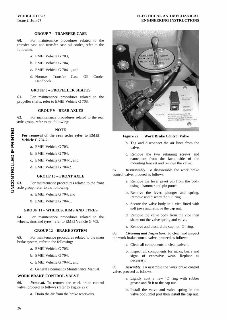
66. Removal. To remove the work brake control valve, proceed as follows (refer to Figure 22):
a. Drain the air from the brake reservoirs.
Figure 22 Work Brake Control Valve
b. Tag and disconnect the air lines from the valve.
c. Remove the two retaining screws and nameplate from the facia side of the mounting bracket and remove the valve.
67. Disassembly. To disassemble the work brake control valve, proceed as follows:
a. Remove the lever pivot pin from the body using a hammer and pin punch.
b. Remove the lever, plunger and spring. Remove and discard the ‘O’ ring.
c. Secure the valve body in a vice fitted with soft jaws and remove the cap nut.
d. Remove the valve body from the vice then shake out the valve spring and valve.
e. Remove and discard the cap nut ‘O’ ring.
68. Cleaning and Inspection. To clean and inspect the work brake control valve, proceed as follows:
a. Clean all components in clean solvent.
b. Inspect all components for nicks, burrs and signs of excessive wear. Replace as necessary.
69. Assembly. To assemble the work brake control valve, proceed as follows:
a. Lightly coat a new ‘O’ ring with rubber grease and fit it to the cap nut.
b. Install the valve and valve spring in the valve body inlet port then install the cap nut.

UN
CO
NTR
OLL
ED IF
PR
INTE
DELECTRICAL AND MECHANICAL VEHICLE D 323 ENGINEERING INSTRUCTIONS Issue 2, Jun 07
27
c. Lightly coat a new ‘O’ ring with rubber grease then fit the ‘O’ ring to the plunger.
d. Install the plunger spring and the plunger into the valve body. Place the lever on top of the plunger and secure it in position with the pin.
70. Installation. To install the work brake control valve, proceed as follows:
a. Position the control valve in the bracket then install the nameplate and retaining screws. Tighten the screws securely.
b. Connect the air lines to their correct positions on the valve and tighten the fittings.
c. Start the engine and allow the brake system air pressure to build up. Check that the control valve operates correctly then shut down the engine.
BRAKE TESTING
71. The brake tests can be carried out using Engine and Brake Performance Test Kit Part No. N50RCA446. For further information relating to the test kit refer to EMEI Vehicle G 703.
WARNING
SERIOUS INJURY CAN OCCUR TO PERSONNEL FROM COMPRESSED AIR. ENSURE THAT PRIOR TO CONNECTION OR DISCONNECTION OF TEST EQUIPMENT TO AIR LINES, ALL PRESSURE IS RELEASED FROM THE CIRCUIT.
72. Truck to Trailer Test. To check that the service brakes are applying in the correct sequence and that the hand control valve is only supplying air to the trailer, proceed as follows:
a. Connect one line of a dual test gauge to the service brake line of the truck as close as possible to a rear brake chamber (Figure 50 gauge 1), and the second line of the gauge to a similar position on the trailer brakes on an axle furthest away from the truck.
b. With the foot brake being applied slowly, both indicators should rise slowly and simultaneously. When the brakes are fully applied, both readings should be identical, with a maximum allowable variation of one graduation. Release the foot brake.
c. Apply the foot brake quickly and check that the trailer indicator rises ahead of the truck indicator. It is acceptable for both gauges to rise together as long as the truck indicator does not rise before the trailer indicator. Release the foot brake.
d. Apply the hand control valve and check that only the trailer indicator rises. Release the hand control valve.
e. Remove the test gauge.
73. Brake Treadle Valve. To test the operation of the treadle valve proceed as follows:
a. Connect two dual test gauges to the brake circuit as follows:
(1) Connect one line of the first gauge to the primary air reservoir (Figure 50 gauge 2A), and the second line of the gauge to the line from the double check valve to the service brake relay valve.
(2) Connect one line of the second gauge to the secondary air reservoir (Figure 50 gauge 2B), and the second line of the gauge to the line from the double check valve to the quick release valve.
b. With the foot brake applied, the treadle valve must deliver a pressure in the primary circuit (Figure 50 gauge 2A) equal to the supply from the primary reservoir, and a pressure in the secondary circuit (Figure 50 gauge 2B) equal to the supply from the secondary reservoir.
c. Remove the test gauges.
74. Service Brake Relay Valve. To test the service brake relay valve, proceed as follows:
a. Connect one line of a dual test gauge to the service brake chamber (Figure 50 gauge 3), and the second line of the gauge to the signal line of the service brake relay valve.
b. Apply the foot brakes and check that both indicators register identical readings. Also check for delays in application and release timings.
c. Remove the test gauge.
75. Work Brake Control Valve. To test the work brake control valve, proceed as follows:
a. Connect one line of a dual test gauge to the line from the double check valve to the service brake relay valve (Figure 50 gauge 4), and the second line of the gauge to the line from the double check valve to the quick release valve.
b. Apply the work brake and check that both indicators register identical readings. Release the work brake.
c. Remove the test gauge.
UN
CO
NTR
OLL
ED IF
PR
INTE
DVEHICLE D 323 ELECTRICAL AND MECHANICAL Issue 2, Jun 07 ENGINEERING INSTRUCTIONS
28
76. Pressure Gauge and Warning Buzzer. To test the pressure gauge and warning buzzer, proceed as follows:
a. Connect one line of a dual test gauge to the primary air reservoir (Figure 50 gauge 5), and the second line of the gauge to the secondary air reservoir.
b. Check the test gauge readings against those of the pressure gauge mounted on the instrument panel.
c. Drain the air from both the primary and secondary air reservoirs until the air compressor is heard to cut-in. The cut-in pressure indicated should be approximately 655 kPa (95 psi). Allow the compressor to operate until full pressure is attained, checking that both indicators rise simultaneously. The compressor cut-out pressure indicated should be approximately 827 kPa (120 psi). The pressures indicated for both reservoirs should be identical throughout this test.
d. Drain the primary air reservoir while maintaining full pressure in the secondary air reservoir and note the pressure that the low air pressure warning light and buzzer are activated. The pressure indicated should be approximately 480 kPa (70 psi). Build up the pressure in the primary air reservoir.
e. Repeat Para 76d for the secondary air reservoir while maintaining full pressure in the primary air reservoir.
f. Remove the test gauge.
77. Spring and Service Brakes. To test the spring and service brakes, proceed as follows:
a. Connect a dual test gauge to the spring brake line and service brake line at the spring brake chamber on a real wheel (Figure 50 gauge 6).
b. With the emergency/parking brake off and the foot brake off, air pressure should be indicated in the spring brake line, but the service brake line should indicate zero.
c. With the emergency/parking brake off and the foot brake on, air pressure should be indicated in both the spring brake and service brake lines.
d. With the emergency/parking brake on and the foot brake off, both the spring brake and service brake lines should indicate zero.
e. With the emergency/parking brake on and the foot brake applied air pressure should be indicated in both the spring brake line and service brake line.
f. Remove the test gauge.
78. Trailer Brake Hand Control Valve. To test the hand control valve, proceed as follows:
a. Connect a dual test gauge to the supply and delivery lines of the hand control valve (Figure 50 gauge 7).
b. With the trailer brake applied, both readings on the test gauge must be identical. Release the trailer brake and remove the test gauge.
79. Start Tank Priming Circuit. To test the start tank priming circuit, proceed as follows:
a. Connect one line of a dual test gauge to the primary air reservoir (Figure 50 gauge 8), and the second line of the gauge to the start tank.
b. With the truck engine running, drain both the primary air reservoir and the start tank, then close the drain cocks. Allow the two tanks to fill and observe the gauges. The primary air reservoir should fill rapidly to approximately 551 kPa (80 psi) before any movement is noticed in the start tank indicator, both tanks should then rise slowly to a maximum pressure of 827 kPa (120 psi), with the primary air reservoir indicator leading the start tank indicator.
c. Shut down the engine then drain the brake reservoirs. Check that the start tank indicator still shows maximum pressure. Start the engine and allow the pressure in the brake reservoirs to build up.
d. Remove the test gauge.
80. Trailer System. To test the trailer system, proceed as follows:
a. Connect a dual test gauge to the service and emergency lines to the trailer (Figure 50 gauge 9).
b. Operate the tractor protection switch on the instrument panel then apply the foot brake. Check that both indicators register maximum pressure. Release the foot brake and the tractor protection switch.
c. Remove the test gauge.

UN
CO
NTR
OLL
ED IF
PR
INTE
DELECTRICAL AND MECHANICAL VEHICLE D 323 ENGINEERING INSTRUCTIONS Issue 2, Jun 07
29
81. Spring Brake Relay Valve. To test the spring brake relay valve, proceed as follows:
a. Connect one line of a dual test gauge to the spring brake line at the spring brake chamber on a rear wheel (Figure 50 gauge 10), and the second line of the gauge to the line from the double check valve to the spring brake relay valve.
b. Engage the emergency/parking brake and check that air pressure is indicated on the input side of the spring brake relay valve, but no air pressure is indicated in the spring brake line.
c. Release the emergency/parking brake and check that air pressure is indicated and that both readings are identical.
d. Remove the test gauge.
GROUP 13 – SUSPENSION
82. Front Suspension. For maintenance procedures related to the front suspension, refer to the following:
a. EMEI Vehicle G 703, and
b. EMEI Vehicle G 704.
83. Rear Suspension. For maintenance procedures related to the rear suspension, refer to the following:
a. EMEI Vehicle G 798-10,
b. EMEI Vehicle G 703-1, and
c. EMEI Vehicle G 704-2.
GROUP 14 – STEERING
84. For maintenance procedures related to the steering, refer to the following:
a. EMEI Vehicle G 703,
b. EMEI Vehicle G 704, and
c. Normax Transfer Case Oil Cooler Handbook.
GROUP 15 – ELECTRICAL
85. For maintenance procedures related to the electrical system not contained in this EMEI, refer to the following:
a. EMEI Vehicle G 703,
b. EMEI Vehicle G 704, and
c. EMEI Vehicle G 704-1.
DISCONNECT THE VEHICLE BATTERIES PRIOR TO COMMENCEMENT OF REPAIRS TO THE ELECTRICAL SYSTEM.
86. Figure 53 illustrates the additional electrical circuits which have been fitted to this vehicle.
RECOVERY ELECTRICAL SYSTEM
87. Power to the recovery unit and crane is supplied via a harness running from the junction blocks located on the left hand side of the firewall and leading to a 16 pin connector located in the forward end of the left hand cabinet of the recovery unit. Protection of the recovery electrical system is provided by a circuit breaker mounted adjacent to the junction blocks on the firewall. The recovery system main electrical circuit diagram is shown at Figure 54.
88. The recovery system remote control wiring circuit is shown at Figure 55.
LIGHTING
Revolving Lamps
89. Removal. To remove the revolving lamps, loosen the wing nut and pull the lamp assembly off the bayonet fitting.
90. Installation. To install the revolving lamps, firstly ensure the terminals within the base and lamp post are clean then push the lamp onto the base until seated and tighten the wing nut.
Crew Cabin Interior Lights
91. Removal. To remove the crew cabin interior lights, proceed as follows:
a. Disconnect the wiring from the light.
b. Remove the mounting screws and lower the light from the roof.
92. Disassembly. Disassemble the crew cab light in accordance with Figure 23.
93. Cleaning and Inspection. To clean and inspect the crew cab light, proceed as follows:
a. Carefully wipe all components with a clean dry cloth if necessary.
b. Inspect all components and ensure all fittings, wiring connectors and globe holders are secure and in good order. Repair or replace unserviceable parts as necessary.
94. Assembly. Assemble the crew cab light in reverse order to disassembly.

UN
CO
NTR
OLL
ED IF
PR
INTE
DVEHICLE D 323 ELECTRICAL AND MECHANICAL Issue 2, Jun 07 ENGINEERING INSTRUCTIONS
30
95. Installation. To install the crew cab light, proceed as follows:
a. Position the light on its mounting and refit the mounting screws.
b. Reconnect the power and test the light.
Figure 23 Crew Cab Light
REVERSING CAMERA SYSTEM
Monitor
96. Removal. To remove the monitor, proceed as follows:
a. Disconnect the vehicle batteries.
b. Remove the screws retaining the instrument panel and carefully manoeuvre the panel out of the dashboard.
c. Remove the thumb screws securing the monitor to the rear of the instrument panel, disconnect the wiring from the monitor and remove it from the instrument panel.
97. Installation. To install the monitor, proceed as follows:
a. Refit the monitor in reverse order to removal.
b. Reconnect the batteries and test the system (refer to the Technical Manual User Handbook).
Cameras
98. Removal. To remove the cameras, proceed as follows:
a. Disconnect the camera cable at the plug located within the control cabinet and feed the plug out through the hole.
b. Undo the mounting screws and remove the camera (refer to Figure 24).
Figure 24 Reversing Camera
99. Installation. Install the camera in the reverse order to disassembly and test the system (refer to Technical Manual User Handbook).
MILITARY RADIO MOUNTS, FITTINGS AND CABLES
General
100. Repairs to military radio components including the cables fitted to the vehicle are to be conducted in accordance with the relevant EMEI. If it is necessary to remove any cables, ensure they are tagged and their mounting locations recorded for correct installation. Refer to the User Handbook for Single Channel Radio System RAVEN B Vehicle and Ground Installations for the configuration of the communications equipment.
Radio Cabling to VHF Antenna and HF Tuner
101. The antenna and HF tuner cabling between the crew cab and rear of the recovery module has been routed from the RHR of the crew cab down to the inside of the RH chassis rail. From here it follows the pneumatic loom rearwards to a point adjacent to the rear bogie where the VHF antenna cable is then routed to the LH side of the vehicle and the HF cables are directed up to the HF antenna tuner in the rear of the RH side cabinet.

UN
CO
NTR
OLL
ED IF
PR
INTE
DELECTRICAL AND MECHANICAL VEHICLE D 323 ENGINEERING INSTRUCTIONS Issue 2, Jun 07
31
102. Take care not to damage radio cables or pneumatic lines during removal and ensure that cables are re-routed via the same path and secured back to the pneumatic loom upon replacement.
RADIO/CD PLAYER
103. Removal. To remove the radio, proceed as follows:
a. To remove the radio/CD player use the removal keys supplied with the new unit.
b. Slide the removal keys into the dash at each end of the unit ensuring the raised section on key shank is facing outwards (refer Figure 25).
c. Hold the unit by the face and pull the unit and keys out of the dash together.
d. Once the unit is clear of the dash, unplug the aerial and wiring connectors.
Figure 25 Radio/CD Player Removal
104. Installation. To install the radio, proceed as follows:
a. Refit the radio in reverse order to removal.
b. Use of the removal keys is not required for installation.
c. Tune and test the system (refer to Technical Manual User Handbook).
GROUP 16 – FRAME
105. For maintenance procedures related to the frame and tow coupling, refer to the following:
a. EMEI Vehicle G 703, and
b. EMEI Vehicle G 799-16.
GROUP 17 – BODY
106. For maintenance procedures related to the body, refer to the following:
a. EMEI Vehicle G 703,
b. EMEI Vehicle G 704, and
c. EMEI Vehicle G 704-1.
BODY
Cab Isolation System
107. Adjustment of Cab Isolation System. To adjust the ride height of the cabin assembly, proceed as follows (refer to Figure 26):
a. Loosen the clamp on the vertical hight control rod and adjust up or down to achieve a 100 mm clearance between the main chassis rail and the cab sub-frame. Measure the clearance at the point adjacent to the cabin air spring station.
b. Once the correct clearance has been obtained re-tighten the clamp on the vertical height control rod.
Figure 26 Cab Isolation – Rear Air Spring
Station
108. Removal. To remove the air springs and dampers, proceed as follows:
a. Drain the air from the truck’s air system.
b. Disconnect the air line from the top of the air spring.
c. Undo the upper and lower retaining nuts from the air spring and remove the assembly.
d. Remove the damper mounting bolts and dampers.
109. Installation. To install the air springs and dampers, proceed as follows:
a. Install the air springs and dampers in reverse order to removal.
b. Reconnect the air line to the top of the air spring.

UN
CO
NTR
OLL
ED IF
PR
INTE
DVEHICLE D 323 ELECTRICAL AND MECHANICAL Issue 2, Jun 07 ENGINEERING INSTRUCTIONS
32
c. Start the truck to charge the air system then check for leaks and adjust the ride height in accordance with Para 107.
GROUP 18 – CAB HEATING/COOLING
110. For maintenance procedures related to the cab heating and cooling systems, refer to the following:
a. EMEI Vehicle G 703,
b. EMEI Vehicle G 704,
c. EMEI Vehicle G 704-1, and
d. Crisp-Air Air Conditioning Handbook.
POWER TAKE-OFFS
PTO CONTROL VALVES
111. Removal. To remove the PTO control valve, proceed as follows:
a. Drain the air from the brake system.
b. Remove the PTO control valve mounting bracket from the floor.
c. Mark and disconnect the air lines from the valve, then remove the valve from the mounting bracket.
112. Installation. To install the PTO control valve proceed as follows:
a. Refit the valve in reverse order to removal.
b. Start the engine to build up air pressure then test the system for correct operation and check for air leaks. Correct faults as required.
HYDRAULIC SUPPLY SYSTEM
113. This section provides maintenance information and procedures related to the hydraulic system components common to both the crane and the recovery module. For specific system information refer to the relevant sections of this EMEI.
WARNING
SERIOUS INJURY CAN OCCUR TO PERSONNEL FROM CONTACT WITH OIL UNDER PRESSURE. ENSURE THAT PRIOR TO DISCONNECTION OF HYDRAULIC HOSES OR COUPLINGS, ALL PRESSURE IS RELEASED FROM THE CIRCUIT.
FLARETITE SEALS
114. The JIC hydraulic fittings used on the recovery module have been fitted with Flaretite seals to extend the life of the fittings and ensure positive sealing. These seals are to be replaced during installation in accordance with Para 115.
115. Replacement. To replace Flaretite seals, proceed as follows:
a. Ensure the conical nose and flared seat of the fittings are clean and free of burrs.
b. Fit the Flaretite seal squarely onto the nose of the male fitting and screw fittings together. Tension in accordance with Table 7.
Table 6 Flaretite Seal Torque Settings
Torque Fitting Size
N.m Lbf.ft
7/16 inch JIC 19 14
9/16 inch JIC 35 26
3/4 inch JIC 75 55
7/8 inch JIC 108 80
11/16 inch JIC 149 110
1-5/16 inch JIC 190 140
1-5/8 inch JIC 258 190
RELIEVING HYDRAULIC PRESSURE
116. Prior to working on the hydraulic system shut the engine down and relieve built up system pressure as follows:
a. Remove the reservoir filler cap to ensure the reservoir has been vented then refit the cap.
b. Cycle all hydraulic control valves fully in both directions to ensure that no pressure has been trapped in the lines or actuators.
c. Carefully crack any fittings being removed to relieve residual pressure.
d. Loosen load holding valve cylinder connections to relieve cylinder pressure before removing the cylinder.
RETURN LINE OIL FILTERS
117. Filter Replacement. To replace the oil filters, proceed as follows (refer to Figure 27):
a. Remove the filter cap.
b. Withdraw the spring, filter element, inner housing and inner housing ‘O’ ring.
c. Remove the cap ‘O’ ring from the filter head and the lower ‘O’ ring from inside the base of the filter housing.

UN
CO
NTR
OLL
ED IF
PR
INTE
DELECTRICAL AND MECHANICAL VEHICLE D 323 ENGINEERING INSTRUCTIONS Issue 2, Jun 07
33
d. Clean and inspect the plastic housing for signs of deterioration and replace if necessary.
e. If necessary, remove, clean and inspect the filter head in accordance with Para 118.
f. Fit new ‘O’ rings to the plastic filter housing and install the housing.
g. Insert a new filter element and spring, then install the cap ‘O’ ring and cap.
Figure 27 Hydraulic Reservoir and Oil Filters
FILTER HEAD
118. Removal. To remove the filter head, proceed as follows:
a. Remove the filter element and inner housing in accordance with Para 117.
b. Remove the two screws securing the filter head to the reservoir then remove the head and ‘O’ ring.
119. Cleaning and Inspection. To clean and inspect the filter head, proceed as follows:
a. Clean the filter head and inspect for damage.
b. Replace if necessary.
120. Installation. To install the filter head, proceed as follows:
a. Fit a new ‘O’ ring to the head, refit into reservoir, install and tighten screws.
b. Refit the inner housing and filter element in reverse order to removal.
OIL COOLER
121. Removal. To remove the oil cooler, proceed as follows:
a. Relieve the hydraulic pressure from the reservoir.
b. Remove the oil cooler cover.
c. Tag and remove the hydraulic lines and wiring from the cooler assembly.
d. Unbolt and remove the cooler assembly from its mounting.
e. Drain the oil from the cooler core into an appropriate container.
122. Disassembly. To disassemble the oil cooler assembly, proceed as follows (refer to Figure 28):
Figure 28 Oil Cooler Assembly
a. Remove the fan assembly from the cooler core.
b. Remove the bypass relief valve from the PRV port (refer to Figure 29).
NOTE Bypass valve pressure setting 207 kPa (30 psi).
RETURN LINE FILTERS
SUCTION STRAINERS (3)
BYPASS VALVE

UN
CO
NTR
OLL
ED IF
PR
INTE
DVEHICLE D 323 ELECTRICAL AND MECHANICAL Issue 2, Jun 07 ENGINEERING INSTRUCTIONS
34
Figure 29 Oil Cooler Bypass Valve
123. Cleaning and Inspection. To clean and inspect the oil cooler assembly, proceed as follows:
a. Blow any dirt out of the core fins using low pressure compressed air.
b. Flush out the cooler and wash the bypass valve components using clean solvent then dry thoroughly.
c. Clean the fan assembly with a cloth and warm soapy water.
d. Visually inspect all components for damage and replace if necessary.
124. Assembly. Assemble the oil cooler in reverse order to disassembly (refer to Figure 28 and Figure 29).
125. Installation. To install the oil cooler assembly, proceed as follows:
a. Install the oil cooler in reverse order to removal.
b. Fit new Flaretite seals to JIC fittings prior to assembly and tighten to prescribed torque settings (refer to Para 115).
BLEEDING HYDRAULIC CIRCUITS
126. After repairs to any hydraulic components, the hydraulic systems must be bled to evacuate all air. If air is left to accumulate in the system the following damage can occur:
a. Cavitation damage to the pump.
b. Slow, jerky crane actions.
c. Automatic ignition (dieseling) resulting in burnt and damaged seals.
127. Crane. To bleed the crane hydraulic circuits, proceed as follows:
a. Start the engine and engage the crane PTO and leave the engine speed at idle.
NOTE Monitor the hydraulic oil level and inspect the system for leaks during the bleeding procedure.
b. Before unfolding the crane, operate the hydraulic cylinders against their stops.
c. Extend the stabiliser cylinders until a load is placed on the leg then fully retract the cylinder and hold it against the stop for 10 to 15 seconds. Repeat this step twice for each leg leaving the stabilisers deployed on completion.
TO AVOID SEAL DAMAGE DURING INITIAL BLEEDING OF THE SLEW CYLINDERS, ONLY USE THE MINIMUM PRESSURE REQUIRED TO MOVE THE CRANE.
d. Fully extend the inner boom. Slew the crane slowly to the left until it reaches the stop and then slowly to the right, again until it reaches the stop.
e. Slew the crane again, slowly to the left until reaching the stop, then slowly apply full pressure for 10 to 15 seconds. At the same time, visually inspect the slew cylinders, hoses and fittings for leaks. Repeat this process, slewing to the right.
f. If no leaks are evident, slew the crane in both directions at normal operating speed.
g. Retract and extend the inner boom cylinder twice, holding full pressure for 10 to 15 seconds at each extent of travel the second time. Repeat this procedure for the outer boom cylinder followed by the boom extension cylinder.
h. Return the crane and stabilisers to the transport position, re-check the oil level and, if necessary, top up.
128. Recovery System. To bleed the recovery hydraulic circuits after repairs, proceed as follows:
a. Start the engine and engage the recovery PTO leaving the engine at idle speed.
NOTE Monitor the hydraulic oil level and inspect the system for leaks during the bleeding procedure.
b. Run the system with all valves in the neutral position for approximately five minutes.
c. Extend and retract all cylinders to their full travel several times and operate the winches in both directions. Check the hydraulic oil level.
UN
CO
NTR
OLL
ED IF
PR
INTE
DELECTRICAL AND MECHANICAL VEHICLE D 323 ENGINEERING INSTRUCTIONS Issue 2, Jun 07
35
NOTE It is only possible to bleed the two secondary winch motors with the winch in low speed high pressure mode. This can only be achieved when the load exceeds three tonnes.
d. Increase the engine speed to 1500 rpm and repeat steps listed at Paras 128b and c.
RECOVERY PLATFORM
WARNING
TO AVOID PINCH AND CRUSH INJURIES, ENSURE THAT NO PART OF THE BODY OR LIMBS IS POSITIONED UNDER THE SPADE ASSEMBLIES OR LIFTING EQUIPMENT AT ANY TIME. LEATHER GLOVES MUST BE WORN AND EXTREME CARE USED WHEN HANDLING WIRE ROPES AND CHAINS.
MECHANICAL SYSTEMS
Hitch Assembly
129. Removal and Disassembly. To remove and disassemble the hitch assembly, proceed as follows (refer to Figure 30):
a. Lower the hitch to the horizontal position and support using appropriate stands.
b. Shut the engine down and relieve the hydraulic pressure in accordance with Para 116.
c. Remove the crossbar pivot pin and lift the crossbar out of the pivot head.
d. Support the main lift cylinder at its lower end using a fabric sling choked around the cylinder and an appropriate crane.
e. Remove the outer tow cylinder pins to disconnect the cylinders from lower pivot shaft then remove the pivot shaft.
f. Assemble the crossbar pivot pin in the pivot head. Support the pivot head assembly by placing a sling around the crossbar pivot pin and take the weight with an appropriate crane.
g. Remove the lift cylinder lower pin to separate the pivot head assembly from the cylinder and lift the assembly clear.
h. Remove the retaining plate from the pivot head pin to separate the pivot head.
i. Fit a suitable bow shackle to either of the cylinder end mounting holes. Reposition the sling on the lift cylinder, placing it around
the piston rod in a choke between the cylinder and piston rod valve block.
j. Using a suitable two legged chain sling and crane, support the weight of the cylinder.
k. Crack loose the hydraulic lines to relieve cylinder pressure then disconnect the fittings and cap hoses and connections.
l. Remove the lift cylinder upper pin and lift the cylinder clear of the vehicle.
m. Crack loose the hydraulic lines on the tow cylinders to relieve pressure then disconnect the fittings and cap hoses and connections.
n. Remove the inner pins from the tow cylinders and lift the cylinders clear.
130. Cleaning and Inspection. To clean and inspect the hitch assembly, proceed as follows:
a. Clean all pins and bushes using clean solvent and dry thoroughly.
b. Measure the pins, bores and bushes in accordance with the specifications. Refer to Figure 30 and Table 8.
131. Assembly and Installation. To assemble and install the hitch assembly, proceed as follows (refer to Figure 30):
a. Grease all pins, bores and bushes prior to assembly using XG-291.
NOTE All spring washers used on the tow hitch are to be replaced during reassembly.
b. Assemble and refit the hitch in the reverse order to removal and disassembly.
c. Bleed the hydraulic system in accordance with Para 128. Inspect and test the system for leaks and correct function.
Sheave Head Assembly
132. Removal. To remove the sheave head assembly, proceed as follows:
a. Remove the cable guide blocks from the cable guide.
b. Remove the sheave pin, cable guide and sheave from the boom end swivel.
c. Remove the three roll pins from the inner end of the boom end swivel and withdraw the assembly.
133. Cleaning and Inspection. To clean and inspect the sheave head assembly, proceed as follows:
a. Clean all components using a pressure cleaner or clean solvent and dry thoroughly.

UN
CO
NTR
OLL
ED IF
PR
INTE
DVEHICLE D 323 ELECTRICAL AND MECHANICAL Issue 2, Jun 07 ENGINEERING INSTRUCTIONS
36
b. Measure the pins, bushings and bores in accordance with the specifications. Refer to Figure 30 and Table 8.
134. Installation. To install the sheave head assembly, proceed as follows:
a. Grease the outside of the boom end swivel tube and sheave bush.

UN
CO
NTR
OLL
ED IF
PR
INTE
DELECTRICAL AND MECHANICAL VEHICLE D 323 ENGINEERING INSTRUCTIONS Issue 2, Jun 07
37
Figure 30 Hitch Assembly

UN
CO
NTR
OLL
ED IF
PR
INTE
DVEHICLE D 323 ELECTRICAL AND MECHANICAL Issue 2, Jun 07 ENGINEERING INSTRUCTIONS
38
Table 7 Recovery System Pin Wear Limits
Item Part Number Description Qty Tolerance
1. 0700563 Fairlead sheave pins 2 62.99 mm (2.48 inch) OD min
2. 0304315 Fairlead sheave bushings 2 64.00 mm (2.52 inch) ID max
3. 18563058 Reversing sheave bushings 2 76.96 mm (3.03 inch) ID max
4. 16607047 Reversing sheave pins 2 Replace when chrome plating is worn through or damaged. Between 76.15 and 76.05 mm (2.998 and 2.994 inch) OD
5. 18567169 Cross bar pivot pin 1 75.82 mm (2.985 inch) OD min
6. 18563003 Cross bar pivot bushing 1 76.71 mm (3.02 inch) ID max
7. 18567246 Pivot head pin (welded to head) 1 75.82 mm (2. 985 inch) OD min
8. 18563004 Pivot head thrust washer 1 2.41 mm (0.095 inch) min thickness
9. 0306879 Pivot head bushing 1 76.71 mm (3.02 inch) ID max
10. 18567198 Tow cylinder pin (outer) 2 37.34 mm (1.47 inch) OD min
11. 18567199 Lift cylinder pin (lower) 1 62.48 mm (2.46 inch) OD min
12. 18567073 Lower pivot shaft
Outer tow cylinder pin holes
1
2
57.79 mm (2.275 inch) OD min
39.37 mm (1.55 inch) ID max
13. 18567191 Tow cylinder pin (inner) 2 24.89 mm (0.98 inch) OD min
14. 18568033 Tow cylinder inner hitch bolt 2 24.64 mm (0.97 inch) OD min
15. 18567170 Lift cylinder pin (upper) 1 50.42 mm (1.985 inch) OD min
16. 16607136 Self recovery sheave pin 1 37.59 mm (1.48 inch) OD min
17. 18567402 Self recovery sheave bushing 1 38.61 mm (1.52 inch) ID max
b. Install the assembly in reverse order to disassembly.
c. Grease the fairlead and boom end swivel tube via the lubrication fittings.
Rear Self Recovery Sheave
135. Removal. Remove the sheave pin and sheave from the fairlead plates.
136. Cleaning and Inspection. To clean and inspect the self recovery sheave, proceed as follows:
a. Clean all components using a pressure cleaner or clean solvent and dry thoroughly.
b. Inspect the components for wear and damage.
c. Measure the pin and bushing in accordance with the specifications. Refer to Figure 30 and Table 8. Replace parts as required.
137. Installation. To install the self recovery sheave, proceed as follows:
a. Grease the pin and bush.
b. Fit the sheave into the fairlead and install the pin.
Reversing Sheaves
138. Removal. To remove the reversing sheaves, proceed as follows:
a. Remove the pin from the top of the frame and feed the rope back through the roller.
b. Disconnect the safety chain from the roller frame, then unbolt and remove the assembly from the platform.
139. Disassembly. To disassemble the reversing sheaves, proceed as follows:
a. Remove the sheave pin and fairlead.
b. Remove the bush retaining plates and press the bush out.
140. Cleaning and Inspection. To clean and inspect the reversing sheaves, proceed as follows:
a. Remove any grease or dirt from the pin and bushing.
b. Inspect the components for wear and damage. Particular attention must be paid to the hard chroming on the pins. If the plating shows signs of wear or has come away from the shaft in any way, the pin must be replaced.

UN
CO
NTR
OLL
ED IF
PR
INTE
DELECTRICAL AND MECHANICAL VEHICLE D 323 ENGINEERING INSTRUCTIONS Issue 2, Jun 07
39
c. Measure the pins and bushings in accordance with the specifications. Refer to Figure 30 and Table 8. Replace parts as required.
141. Assembly. To assemble the reversing sheaves, proceed as follows:
a. Press a new bush in.
b. Refit the bush retaining plates.
c. Refit the fairlead and sheave pin.
142. Installation. Install the reversing sheaves in reverse order to removal and tension the mounting bolts to 460 N.m (340 lbf.ft).
RECOVERY FRAME REPAIR
DISCONNECT THE VEHICLE BATTERIES AND REMOVE BOTH PLUGS FROM THE WINCH PROGRAMMABLE LOGIC CONTROLLER (PLC) BOXES PRIOR TO COMMENCING ANY WELDING TASKS.
143. Welding. The recovery frame is manufactured from Domex 100 000 lb yield strength steel. All repairs can be carried out using standard welding procedures and filler materials in accordance with current standards.
HYDRAULIC SYSTEM
TO PREVENT CONTAMINATION AND DAMAGE TO HYDRAULIC COMPONENTS, REPAIRS MUST BE CARRIED OUT IN A CLEAN DUST FREE ENVIRONMENT.
144. Figure 52 shows the hydraulic circuit for the recovery system.
Tow Cylinders
145. Removal. To remove the tow cylinders, proceed as follows:
a. Lower the three point linkage to the ground, shut down the engine and relieve the hydraulic pressure from the reservoir and extension cylinders.
b. Tag, remove and cap the hydraulic lines and fittings.
c. Remove the pins securing the cylinders in place and remove the cylinders.
146. Installation. To install the tow cylinders, proceed as follows:
a. Install the cylinders in reverse order to removal.
b. Check and top up the hydraulic reservoir.
c. Start the engine and bleed the hydraulics (refer to Para 128). Test the system for correct operation and inspect for leaks.
Main Lift Cylinder
147. Removal. To remove the main lift cylinder, proceed as follows:
a. Lower the lift linkage to the ground so that the weight is removed from the lift cylinder, shut the engine down and relieve hydraulic pressure from the reservoir and the lift circuit.
b. Remove the two pins securing the cylinder to the cross bar then retract the piston.
c. Attach appropriate lifting equipment (refer to Para 129i to l).
148. Installation. To install the main lift cylinder, proceed as follows:
a. Grease all pins and bushes, then install the main lift cylinder in reverse order to removal.
b. Check and top up the hydraulic reservoir.
c. Bleed the system in accordance with Para 128, test for correct operation of the cylinder and check for leaks.
d. Pump grease into all grease nipples.
Spade Cylinders
149. Removal. To remove a spade cylinder, proceed as follows:
WARNING
ENSURE NO PART OF THE BODY OR LIMBS IS POSITIONED UNDER THE SPADE ASSEMBLY AT ANY TIME DURING REMOVAL OR INSTALLATION.
a. Lower the spade to the ground, shut the engine down and relieve hydraulic pressure in accordance with Para 116.
b. Remove the grub screw and lock nut locking the retaining pin into the piston end of the cylinder. A hole has been provided in the front of the inner leg to access the grub screw and lock nut.
c. Remove the pin.
d. Remove the cover plate from top of the spade housing.
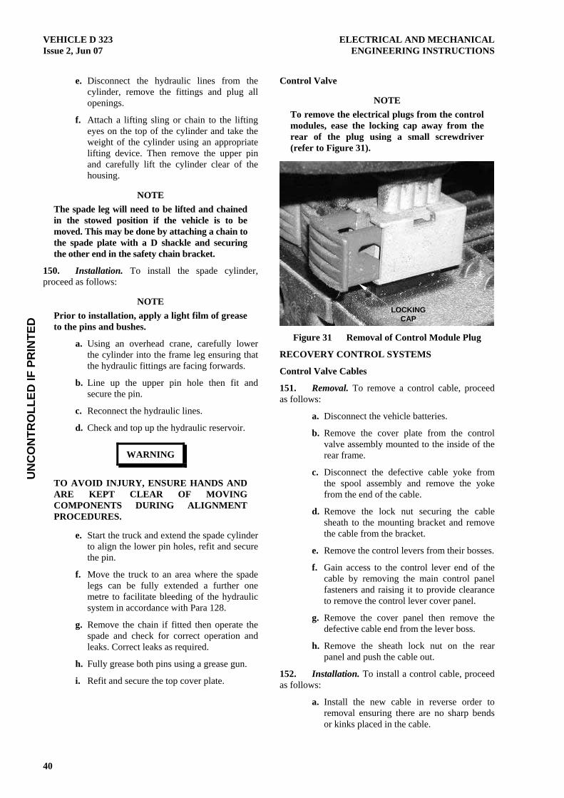
UN
CO
NTR
OLL
ED IF
PR
INTE
DVEHICLE D 323 ELECTRICAL AND MECHANICAL Issue 2, Jun 07 ENGINEERING INSTRUCTIONS
40
e. Disconnect the hydraulic lines from the cylinder, remove the fittings and plug all openings.
f. Attach a lifting sling or chain to the lifting eyes on the top of the cylinder and take the weight of the cylinder using an appropriate lifting device. Then remove the upper pin and carefully lift the cylinder clear of the housing.
NOTE The spade leg will need to be lifted and chained in the stowed position if the vehicle is to be moved. This may be done by attaching a chain to the spade plate with a D shackle and securing the other end in the safety chain bracket.
150. Installation. To install the spade cylinder, proceed as follows:
NOTE Prior to installation, apply a light film of grease to the pins and bushes.
a. Using an overhead crane, carefully lower the cylinder into the frame leg ensuring that the hydraulic fittings are facing forwards.
b. Line up the upper pin hole then fit and secure the pin.
c. Reconnect the hydraulic lines.
d. Check and top up the hydraulic reservoir.
WARNING
TO AVOID INJURY, ENSURE HANDS AND ARE KEPT CLEAR OF MOVING COMPONENTS DURING ALIGNMENT PROCEDURES.
e. Start the truck and extend the spade cylinder to align the lower pin holes, refit and secure the pin.
f. Move the truck to an area where the spade legs can be fully extended a further one metre to facilitate bleeding of the hydraulic system in accordance with Para 128.
g. Remove the chain if fitted then operate the spade and check for correct operation and leaks. Correct leaks as required.
h. Fully grease both pins using a grease gun.
i. Refit and secure the top cover plate.
Control Valve
NOTE To remove the electrical plugs from the control modules, ease the locking cap away from the rear of the plug using a small screwdriver (refer to Figure 31).
Figure 31 Removal of Control Module Plug
RECOVERY CONTROL SYSTEMS
Control Valve Cables
151. Removal. To remove a control cable, proceed as follows:
a. Disconnect the vehicle batteries.
b. Remove the cover plate from the control valve assembly mounted to the inside of the rear frame.
c. Disconnect the defective cable yoke from the spool assembly and remove the yoke from the end of the cable.
d. Remove the lock nut securing the cable sheath to the mounting bracket and remove the cable from the bracket.
e. Remove the control levers from their bosses.
f. Gain access to the control lever end of the cable by removing the main control panel fasteners and raising it to provide clearance to remove the control lever cover panel.
g. Remove the cover panel then remove the defective cable end from the lever boss.
h. Remove the sheath lock nut on the rear panel and push the cable out.
152. Installation. To install a control cable, proceed as follows:
a. Install the new cable in reverse order to removal ensuring there are no sharp bends or kinks placed in the cable.
LOCKING CAP
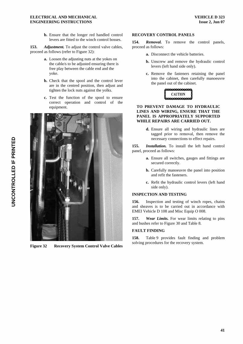
UN
CO
NTR
OLL
ED IF
PR
INTE
DELECTRICAL AND MECHANICAL VEHICLE D 323 ENGINEERING INSTRUCTIONS Issue 2, Jun 07
41
b. Ensure that the longer red handled control levers are fitted to the winch control bosses.
153. Adjustment. To adjust the control valve cables, proceed as follows (refer to Figure 32):
a. Loosen the adjusting nuts at the yokes on the cable/s to be adjusted ensuring there is free play between the cable end and the yoke.
b. Check that the spool and the control lever are in the centred position, then adjust and tighten the lock nuts against the yolks.
c. Test the function of the spool to ensure correct operation and control of the equipment.
Figure 32 Recovery System Control Valve Cables
RECOVERY CONTROL PANELS
154. Removal. To remove the control panels, proceed as follows:
a. Disconnect the vehicle batteries.
b. Unscrew and remove the hydraulic control levers (left hand side only).
c. Remove the fasteners retaining the panel into the cabinet, then carefully manoeuvre the panel out of the cabinet.
TO PREVENT DAMAGE TO HYDRAULIC LINES AND WIRING, ENSURE THAT THE PANEL IS APPROPRIATELY SUPPORTED WHILE REPAIRS ARE CARRIED OUT.
d. Ensure all wiring and hydraulic lines are tagged prior to removal, then remove the necessary connections to effect repairs.
155. Installation. To install the left hand control panel, proceed as follows:
a. Ensure all switches, gauges and fittings are secured correctly.
b. Carefully manoeuvre the panel into position and refit the fasteners.
c. Refit the hydraulic control levers (left hand side only).
INSPECTION AND TESTING
156. Inspection and testing of winch ropes, chains and sheaves is to be carried out in accordance with EMEI Vehicle D 108 and Misc Equip O 008.
157. Wear Limits. For wear limits relating to pins and bushes refer to Figure 30 and Table 8.
FAULT FINDING
158. Table 9 provides fault finding and problem solving procedures for the recovery system.

UN
CO
NTR
OLL
ED IF
PR
INTE
DVEHICLE D 323 ELECTRICAL AND MECHANICAL Issue 2, Jun 07 ENGINEERING INSTRUCTIONS
42
Table 8 Recovery System Fault Finding
Symptom Probable Cause Action
No or poor hydraulic function
a. Low oil level Check and top up.
Check all hydraulic lines, fittings and components for leaks.
b. Hydraulic isolation valve/s closed Ensure the hydraulic isolation valves under the tank are all open.
c. PTO or pump fault Inspect the PTO and tandem pump for correct operation.
1.
d. Control valve or control cable fault Check that the spool valve is moving when the lever or button on the remote pendant is actuated. If not, inspect the control cables, electrical and pneumatic circuits for correct operation.
Recovery system will not operate via remote control pendant or right hand control switches.
a. Electrical fault Check that the remote isolation switch is in the ON position and inspect the condition of wiring and connections in the remote control circuit (refer to Figure 55).
Inspect the spool actuators on the main control valve for correct operation.
2.
b. Pneumatic fault Inspect the pneumatic system for leaks and ensure that the regulator is set to between 480 and 550 kPa (refer to Figure 51).
PNEUMATIC SYSTEM
PNEUMATIC SUPPLY MANIFOLD
159. Removal. To remove the pneumatic manifold, proceed as follows (refer to Figure 33):
NOTE The pneumatic supply manifold is located on the chassis cross member above the propeller shaft centre bearing.
a. Drain the air from the brake reservoirs.
b. Tag and remove all air lines then remove the manifold block.
160. Installation. To install the pneumatic manifold, proceed as follows:
a. Secure the manifold block to the cross member.
b. Apply teflon thread tape to the threads of all fittings and refit in the correct ports.
c. Charge the air system and check for leaks.
Figure 33 Pneumatic Supply Manifold
RECOVERY PNEUMATIC SYSTEM
161. Figure 51 illustrates the pneumatic system layout for the recovery unit.
Pneumatic System Lubricator Adjustment
162. The lubricator is to be adjusted so that each time a pneumatic operation is carried out, (eg; winch disengagement cylinder is operated) one drop of oil is dispensed through the sight feed dome. To achieve this, proceed as follows:
a. Ensure there is 480 to 550 kPa of air pressure at the regulator.
b. Watch the sight feed dome while an assistant operates a pneumatic function and count the number of drops dispersed as the air flows through the lubricator.
c. Turn the adjusting screw to obtain a setting of one drop of oil each time a function is

UN
CO
NTR
OLL
ED IF
PR
INTE
DELECTRICAL AND MECHANICAL VEHICLE D 323 ENGINEERING INSTRUCTIONS Issue 2, Jun 07
43
operated. Turn the adjusting screw anticlockwise to increase and clockwise to decrease the drip rate.
d. Monitor the components being lubricated for a few days following initial adjustment. Adjust the drip rate if the oil delivery at the components appears too high or too low.
WINCHES
163. Figure 34 identifies and shows the location of the main winch components. Figure 35 shows the hydraulic circuit for the winch valve block.
164. Table 10 provides a list of torque settings for the fasteners used on the winch assemblies. Refer to the RPS for information on screw and bolt grades.
Table 9 Winch Fastener Torques
Torque N.m
Fastener Grade
Thread
8.8 10.9 12.9
M6 9.5 12 18.2
M8 24 30 43
M10 47 59 84.5
M12 84 105 146
M16 210 - 356
WINCH INSPECTION AND TESTING
165. Inspection. To inspect the winch, proceed as follows:
a. Visually inspect the following components for signs of damage or wear:
(1) Inspect the pressure plate for excessive grooving and sharp edges which may damage the rope.
(2) Inspect the components of the drum level sensing device.
(3) Ensure that the tamperproof caps on the valve block are fitted and intact.
Figure 34 Right Winch
PNEUMATIC DISENGAGEMENT
(FREE SPOOL) CYLINDER
HYDRAULIC BRAKE
PRIMARY DRIVE (OMH 250 MOTOR)
SECONDARY DRIVE A (OMH 200
MOTOR) DRAG BRAKE
SECONDARY DRIVE B (OMT 200
MOTOR)
HYDRAULIC VALVE BLOCK
PRESSURE PLATE
DRUM LEVEL SENSING DEVICE
CLUTCH GEAR WHEEL
V SEAL
LOCATION OF MOISTURE
DRAIN PLUG