Embed Size (px)
Citation preview
379
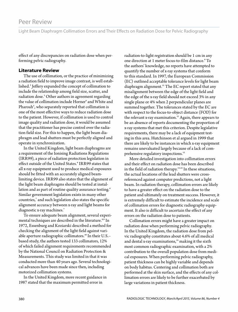
Peer Review
RADIOLOGIC TECHNOLOGY, March/April 2015, Volume 86, Number 4
diaphragm and the actual radiation field are likely to affect the overall radiation dose for the examination.
Radiographic centering and collimation are rou-tinely performed at the skin surface. Discrepancies between the light beam and the actual radiation field size could be exacerbated by extremes in patient thick-ness; however, this is likely more of a problem in pelvic radiography because patient thickness can be highly variable. The aim of this study was to quantify the effects of any discrepancies between the visually esti-mated radiation field size (light beam diaphragm) and actual radiation field size, and to assess the subsequent
Light beam diaphragms are devices used in diag-nostic radiography to provide a visual indication of the radiation field size delivered to a patient.1 The construction of the device is simple. An
electric lamp produces light that is reflected by mirrors along the x-ray beam path. The mirrors are set into 2 opposing metal plates called shutters that produce a rectangular field.2 The light beam diaphragm serves 2 purposes: It allows collimation of the x-ray field size, ensuring that only the required anatomy is irradiated, and it aids correct radiographic centering of the x-ray beam.1 Any inaccuracies between the light beam
Purpose To investigate the range of collimation errors in x-ray rooms and to calculate their possible effects on the radia-tion dose for anteroposterior pelvic examinations.
Methods A collimator test tool was suspended at 3 heights (14, 21, and 28 cm) above the table Bucky in 9 x-ray rooms. Heights corresponded to the typical patient thickness (mean, 2 SD) of 67 patients undergoing anteroposterior pelvic radiography. The x-ray beam was visually collimated to the inner boundary of the test tool and exposed to radiation. Differences between the visualized field size and the resultant x-ray field size (corrected for magnification) indicated a collimation error. Next, using a pelvic phantom, minimum textbook collimation was set and then changed and verified to simulate a range of possible collimation errors. Phantom examinations used a standard anteroposterior technique with exposure termination using outer automatic exposure control chambers. Dose area product (DAP) was recorded.
Results All but 1 of the 9 x-ray machines had a smaller irradiated area than was visually set. Errors ranged from a 16% reduc-tion in irradiated field size to a slight overirradiation by 0.4%. Assuming that these errors could be larger in other institutions, additional errors with a range of 27% to 18% were simulated. Increases in field size by 1 cm (superiorly/inferiorly) increased the DAP by 5%. Laterally, a 1-cm increase caused a 4% rise in DAP. Increases of 1 cm in both planes raised DAP by 4%.
Discussion Within a single clinical department, minimal collimation errors were demonstrated. Further evidence from multiple centers would be beneficial; however, such low incidences might reflect strict legislative requirements gov-erning the use of ionizing radiation. Understanding the magnitude of any error is important, but it is also important to ascertain an error’s influence on the effective radiation dose for any given examination.
Conclusion Overall, collimation errors were minimal and favored underirradiation. Small collimation errors can affect DAP and are more dose significant in the superior/inferior plane.
Hannah Brookfield, BSc(Hons)Anthony Manning-Stanley, BSc(Hons)
Andrew England, BSc(Hons), PgCert, MSc, PhD, FHEA
Light Beam Diaphragm Collimation Errors and Their Effects on Radiation Dose for Pelvic Radiography
380
Peer Review
RADIOLOGIC TECHNOLOGY, March/April 2015, Volume 86, Number 4
Light Beam Diaphragm Collimation Errors and Their Effects on Radiation Dose for Pelvic Radiography
effect of any discrepancies on radiation dose when per-forming pelvic radiography.
Literature Review The use of collimation, or the practice of minimizing
a radiation field to improve image contrast, is well estab-lished.3 Jeffery expanded the concept of collimation to include the relationship among field size, scatter, and radiation dose.3 Other authors in agreement regarding the value of collimation include Horner4 and White and Pharoah5, who separately reported that collimation is one of the most effective ways to reduce radiation dose to the patient. However, if collimation is used to control image quality and radiation dose, it would be assumed that the practitioner has precise control over the radia-tion field size. For this to happen, the light beam dia-phragm and lead shutters must be perfectly aligned and operate in synchronization.
In the United Kingdom, light beam diaphragms are a requirement of the Ionising Radiations Regulations (IRR99), a piece of radiation protection legislation in effect outside of the United States.6 IRR99 states that all x-ray equipment used to produce medical exposures should be fitted with an accurately aligned beam-limiting device. IRR99 also states that the alignment of the light beam diaphragms should be tested at instal-lation and as part of routine quality assurance testing.6 Similar government legislation exists in many other countries,7 and such legislation also states the specific alignment accuracy between x-ray and light beams for diagnostic x-ray machines.7
To ensure adequate beam alignment, several experi-mental techniques are described in the literature.8,9 In 1972, Essenburg and Koziarski described a method for checking the alignment of the light field against vari-able aperture radiographic collimators.10 In their U.S.–based study, the authors tested 133 collimators, 12% of which failed alignment requirements recommended by the National Council on Radiation Protection & Measurements. This study was limited in that it was conducted more than 40 years ago. Several technologi-cal advances have been made since then, including motorized collimation systems.
In the United Kingdom, more recent guidance in 1987 stated that the maximum permitted error in
radiation-to-light registration should be 1 cm in any one direction at 1 meter focus-to-film distance.9 To the authors’ knowledge, no reports have attempted to quantify the number of x-ray systems that conform to this standard. In 1997, the European Commission (EC) outlined acceptable tolerance levels for light beam diaphragm alignment.11 The EC report stated that any misalignment between the edge of the light field and the edge of the x-ray field should not exceed 3% in any single plane or 4% when 2 perpendicular planes are summed together. The tolerances stated by the EC are with respect to the focus-to-object distance (FOD) for the relevant x-ray examination.11 Again, there appears to be an absence of reports documenting the proportion of x-ray systems that met this criterion. Despite legislative requirements, there may be a lack of equipment test-ing in this area. Hutchinson et al argued in 1999 that there are likely to be instances in which x-ray equipment remains unevaluated largely because of a lack of com-prehensive regulatory inspections.12
More detailed investigation into collimation errors and their effect on radiation dose has been described in the field of radiation therapy.13,14 In these situations, the actual locations of the lead shutters were cross-referenced against computer predictions, not a light beam. In radiation therapy, collimation errors are likely to have a greater effect on the radiation dose to the patient and ultimately on treatment success. However, it is extremely difficult to estimate the incidence and scale of collimation errors for diagnostic radiography equip-ment. It also is difficult to ascertain the effect of any errors on the radiation dose to patients.
Collimation errors might have a greater impact on radiation dose when performing pelvic radiography. In the United Kingdom, the radiation dose from pel-vic radiography constitutes about 4.6% of all medical and dental x-ray examinations,15 making it the sixth most common radiographic examination, with a 2% contribution to the overall population dose from medi-cal exposures. When performing pelvic radiography, patient thickness can be highly variable and depends on body habitus. Centering and collimation both are performed at the skin surface, and the effects of any col-limation errors are likely to be further exacerbated by large variations in patient thickness.
381
Peer Review
RADIOLOGIC TECHNOLOGY, March/April 2015, Volume 86, Number 4
Brookfield, Manning-Stanley, England
MethodsPatient Thickness
A previously acquired database contained data on patient thickness measured at the radiographic center-ing point for an anteroposterior (AP) pelvis examina-tion (in the midsagittal plane, midway between the anterior superior iliac spine and the superior border of the symphysis pubis). Data from 67 patients were ana-lyzed and found to be approximately normally distrib-uted. Using these data, the mean patient thickness (at the radiographic centering point) was 21 cm. To under-stand the likely extreme ranges of patient thickness,
data were reported at 2 standard deviations (14 and 28 cm).
Clinical Collimation ErrorsBecause centering and collimation decisions rou-
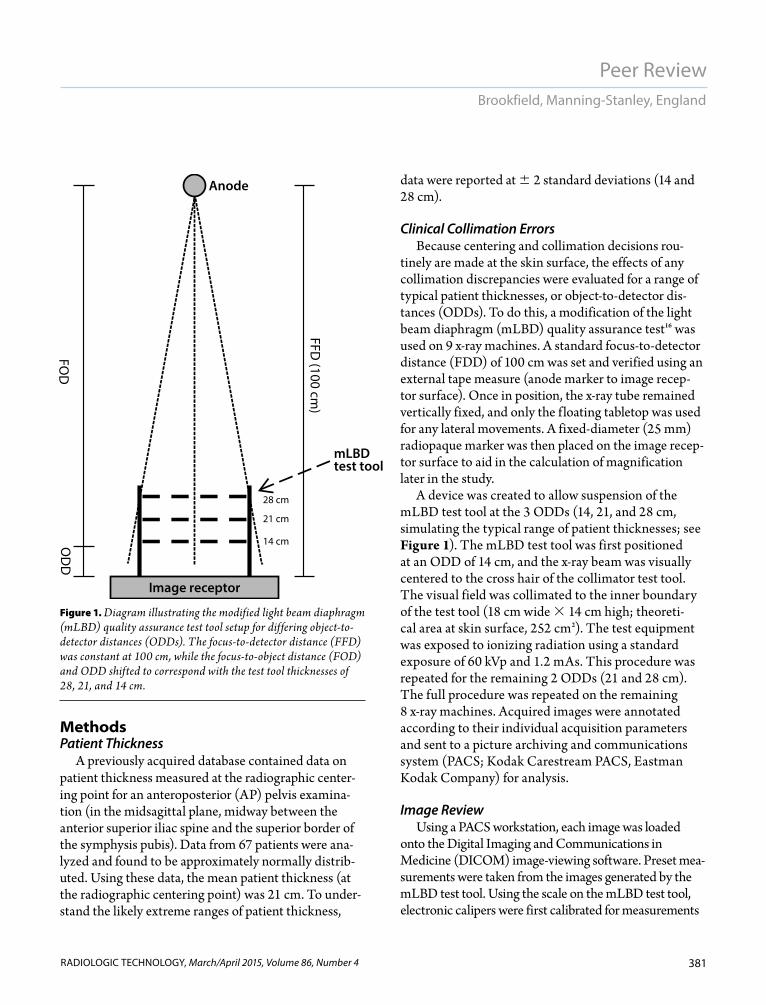
tinely are made at the skin surface, the effects of any collimation discrepancies were evaluated for a range of typical patient thicknesses, or object-to-detector dis-tances (ODDs). To do this, a modification of the light beam diaphragm (mLBD) quality assurance test16 was used on 9 x-ray machines. A standard focus-to-detector distance (FDD) of 100 cm was set and verified using an external tape measure (anode marker to image recep-tor surface). Once in position, the x-ray tube remained vertically fixed, and only the f loating tabletop was used for any lateral movements. A fixed-diameter (25 mm) radiopaque marker was then placed on the image recep-tor surface to aid in the calculation of magnification later in the study.
A device was created to allow suspension of the mLBD test tool at the 3 ODDs (14, 21, and 28 cm, simulating the typical range of patient thicknesses; see Figure 1). The mLBD test tool was first positioned at an ODD of 14 cm, and the x-ray beam was visually centered to the cross hair of the collimator test tool. The visual field was collimated to the inner boundary of the test tool (18 cm wide 14 cm high; theoreti-cal area at skin surface, 252 cm2). The test equipment was exposed to ionizing radiation using a standard exposure of 60 kVp and 1.2 mAs. This procedure was repeated for the remaining 2 ODDs (21 and 28 cm). The full procedure was repeated on the remaining 8 x-ray machines. Acquired images were annotated according to their individual acquisition parameters and sent to a picture archiving and communications system (PACS; Kodak Carestream PACS, Eastman Kodak Company) for analysis.
Image Review Using a PACS workstation, each image was loaded
onto the Digital Imaging and Communications in Medicine (DICOM) image-viewing software. Preset mea-surements were taken from the images generated by the mLBD test tool. Using the scale on the mLBD test tool, electronic calipers were first calibrated for measurements
mLBD test tool
Image receptor
Anode
28 cm
21 cm
14 cmOD
DFO
D
FFD (100 cm
)
Figure 1. Diagram illustrating the modified light beam diaphragm (mLBD) quality assurance test tool setup for differing object-to-detector distances (ODDs). The focus-to-detector distance (FFD) was constant at 100 cm, while the focus-to-object distance (FOD) and ODD shifted to correspond with the test tool thicknesses of 28, 21, and 14 cm.
382
Peer Review
RADIOLOGIC TECHNOLOGY, March/April 2015, Volume 86, Number 4
Light Beam Diaphragm Collimation Errors and Their Effects on Radiation Dose for Pelvic Radiography
at the surface of the tool (ODD). The centering error (the difference between the light beam center and the center of the radiation field) and the radiation field size error (the difference between the area of the light beam and the area of the radiation field) were determined.
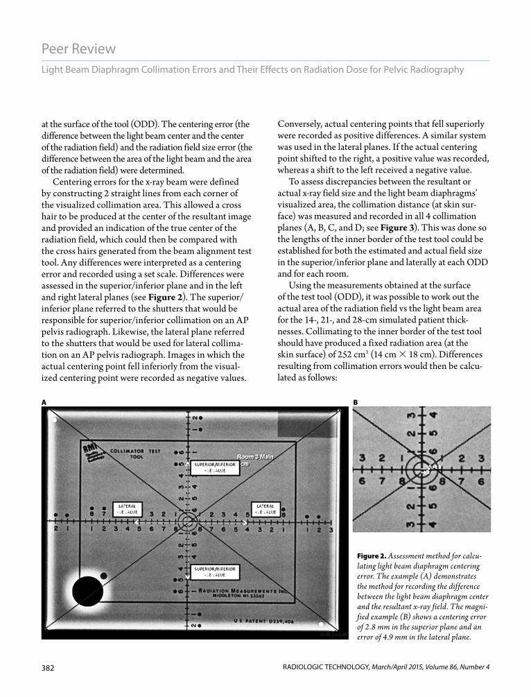
Centering errors for the x-ray beam were defined by constructing 2 straight lines from each corner of the visualized collimation area. This allowed a cross hair to be produced at the center of the resultant image and provided an indication of the true center of the radiation field, which could then be compared with the cross hairs generated from the beam alignment test tool. Any differences were interpreted as a centering error and recorded using a set scale. Differences were assessed in the superior/inferior plane and in the left and right lateral planes (see Figure 2). The superior/inferior plane referred to the shutters that would be responsible for superior/inferior collimation on an AP pelvis radiograph. Likewise, the lateral plane referred to the shutters that would be used for lateral collima-tion on an AP pelvis radiograph. Images in which the actual centering point fell inferiorly from the visual-ized centering point were recorded as negative values.
Conversely, actual centering points that fell superiorly were recorded as positive differences. A similar system was used in the lateral planes. If the actual centering point shifted to the right, a positive value was recorded, whereas a shift to the left received a negative value.
To assess discrepancies between the resultant or actual x-ray field size and the light beam diaphragms’ visualized area, the collimation distance (at skin sur-face) was measured and recorded in all 4 collimation planes (A, B, C, and D; see Figure 3). This was done so the lengths of the inner border of the test tool could be established for both the estimated and actual field size in the superior/inferior plane and laterally at each ODD and for each room.
Using the measurements obtained at the surface of the test tool (ODD), it was possible to work out the actual area of the radiation field vs the light beam area for the 14-, 21-, and 28-cm simulated patient thick-nesses. Collimating to the inner border of the test tool should have produced a fixed radiation area (at the skin surface) of 252 cm2 (14 cm 18 cm). Differences resulting from collimation errors would then be calcu-lated as follows:
Figure 2. Assessment method for calcu-lating light beam diaphragm centering error. The example (A) demonstrates the method for recording the difference between the light beam diaphragm center and the resultant x-ray field. The magni-fied example (B) shows a centering error of 2.8 mm in the superior plane and an error of 4.9 mm in the lateral plane.
A B

383
Peer Review
RADIOLOGIC TECHNOLOGY, March/April 2015, Volume 86, Number 4
Brookfield, Manning-Stanley, England
VisualizedAreas 14 cm 18 cm 252 cm2
Radiation fieldAreas h1 w1
Area difference VisualizedAreas Radiation fieldAreas
AreaS denotes the area at the skin (test tool) surface; h1 and w1 correspond to the mean height (A C/2) and width (B D/2) of the actual radiation field size at the respective level of the test tool.
The volume of irradiated tissue is given using the formula for a frustum. A frustum is created when a pyramid or cone-shaped object is divided on a plane parallel to its base. It also is possible to calculate the dif-ferences in irradiated volumes that result from collima-tion errors. The formula for the volume of a frustum is
V — AreaS AreaD √AreaS AreaD
AreaS is the area at the tool surface (or skin), whereas AreaD is the area at the detector surface; d is the depth
of tissue, or the patient thickness or ODD. In our experimental situation, the irradiated area at the detector (actual or theoretical) could be calculated using the magnification factor (Mf) for the rel-evant tissue thickness:
Mf —————
Based on a visualized field of 252 cm2 at the skin and tool surface and a 14-cm tissue thick-ness, the volume of the resultant frustum can be found with the following formula:
Mf(14 cm) ———— 1.16
AreaS 14 cm 18 cm 252 cm2
AreaD (1.16 14 cm) ( 1.16 18 cm) 338.6 cm2
TheoreticalVolume — 252 338.6
√252 338.6 4122.2 cm3
Using the collimation error values obtained from the clinical experiment and the formula for a frustum, the differences between the theoreti-cal volume (based on a 252 cm2 irradiated skin area) then could be calculated. In the event that
only minimal collimation errors were encountered, a range of possible errors and their effects on radiation dose were simulated in the subsequent experiment.
Dosimetry SimulationA range of collimation errors and their resultant
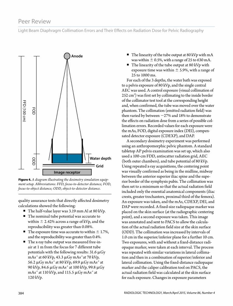
effects on dose area product (DAP) for AP pelvis radio-graphic examinations was simulated. This phase of the experiment was performed in a university department using a GE Definium 6000 digital x-ray machine (GE Healthcare). The simulation consisted of a water bath, tape measure, beam alignment test tool, and meter rule. The water bath was filled to the corresponding depths of 14 cm, 21 cm, and 28 cm (see Figure 4).
The department routinely engages in a quality assurance program, including checks on the x-ray tube-generator, beam quality, automatic exposure control (AEC), and detector. In particular, the results of prior
d3
d FDDFDD
14 8686
14 3Figure 3. Method for assessing collimation field size errors. In this example, the
lengths of sides B and D (superior/inferior shutters) were recorded as 13.3 cm and 13.4 cm, respectively. The visually set values, using the LBD, were 14 cm. This generated errors of –0.7 cm and –0.6 cm, respectively. Errors of –0.3 cm and –0.2 cm were displayed for the lateral shutters; sides A and C had actual lengths of 17.7 cm and 17.8 cm instead of a visually set 18 cm.
384
Peer Review
RADIOLOGIC TECHNOLOGY, March/April 2015, Volume 86, Number 4
Light Beam Diaphragm Collimation Errors and Their Effects on Radiation Dose for Pelvic Radiography
quality assurance tests that directly affected dosimetry calculations showed the following: The half-value layer was 3.19 mm Al at 80 kVp. The nominal tube potential was accurate to
within 2.42% across a range of kVp, and the reproducibility was greater than 0.08%.
The exposure time was accurate to within 1.7%, and the reproducibility was greater than 0.4%.
The x-ray tube output was measured free-in-air at 1 m from the focus for 7 different tube potentials with the following results: 31.6 Gy mAs-1 at 60 kVp, 43.3 Gy mAs-1 at 70 kVp, 56.2 Gy mAs-1 at 80 kVp, 69.9 Gy mAs-1 at 90 kVp, 84.6 Gy mAs-1 at 100 kVp, 99.8 Gy mAs-1 at 110 kVp, and 115.5 Gy mAs-1 at 120 kVp.
The linearity of the tube output at 80 kVp with mA was within 0.5%, with a range of 25 to 630 mA.
The linearity of the tube output at 80 kVp with exposure time was within 5.9%, with a range of 25 to 1000 ms.
For each of the 3 depths, the water bath was exposed to a pelvis exposure of 80 kVp, and the single central AEC was used. A control exposure (visual collimation of 252 cm2) was first set by collimating to the inside border of the collimator test tool at the corresponding height and, when confirmed, the tube was moved over the water phantom. The collimation (emitted radiation field) was then varied by between 27% and 18% to demonstrate the effects on radiation dose from a series of possible col-limation errors. Recorded values for each exposure were the mAs, FOD, digital exposure index (DEI), compen-sated detector exposure (CDEXP), and DAP.
A secondary dosimetry experiment was performed using an anthropomorphic pelvic phantom. A standard tabletop AP pelvis examination was set up, which also used a 100-cm FDD, antiscatter radiation grid, AEC (both outer chambers), and tube potential of 80 kVp. Using repeated x-ray acquisitions, the centering point was visually confirmed as being in the midline, midway between the anterior superior iliac spine and the supe-rior border of the symphysis pubis. The collimation was then set to a minimum so that the actual radiation field included only the essential anatomical components (iliac crests, greater trochanters, proximal third of the femora). An exposure was taken, and the mAs, CDEXP, DEI, and DAP were recorded. A fixed-size radiopaque marker was placed on the skin surface (at the radiographic centering point), and a second exposure was taken. This image was annotated and sent to PACS to allow the calcula-tion of the actual radiation field size at the skin surface (ODD). The collimation was increased by intervals of 1.0 cm in the superior/inferior plane for a further 10 cm. Two exposures, with and without a fixed-distance radi-opaque marker, were taken at each interval. The process was repeated with similar variations in lateral collima-tion and then in a combination of superior/inferior and lateral collimation. Using the fixed-distance radiopaque marker and the caliper calibration tool on PACS, the actual radiation field was calculated at the skin surface for each exposure. Changes in exposure parameters
Figure 4. A diagram illustrating the dosimetry simulation equip-ment setup. Abbreviations: FFD, focus-to-detector distance; FOD, focus-to-object distance; ODD, object-to-detector distance.
Water depth
Image receptor
Anode
Grid
OD
DFO
D
FFD (100 cm
)

385
Peer Review
RADIOLOGIC TECHNOLOGY, March/April 2015, Volume 86, Number 4
Brookfield, Manning-Stanley, England
could be investigated against subtle changes in field size, which could mimic clinical collimation errors.
Statistical AnalysisData were transferred to an
Excel (Microsoft) spreadsheet, and statistical analysis was per-formed using SPSS Statistics 20.0 (IBM). Means, medians, and stan-dard deviations were calculated for all lengths, areas, volumes, and DAP readings. Comparisons of continuous variables were per-formed with an unpaired Student t test in cases of normal distribu-tion and with the Mann-Whitney U test otherwise. The correlation between continuous variables with normal distribution was carried out using Pearson’s cor-relation test. A P value of less than .05 was considered statistically significant.
ResultsBeam Centering Errors
Centering errors were observed in both the lateral and superior/infe-rior planes (see Table 1). A single x-ray machine had an error of zero at 14 cm, which was maintained at 21 cm. One other machine had zero error at 21 cm, and 2 machines had zero error at 28 cm. The worst superior/inferior errors recorded were 0.9 to 0.9 cm. The 0.9 cm was recorded at the 28-cm thickness, and the 0.9 cm at the 14-cm thick-ness. Centering accuracy also was assessed in the lateral planes; 1 room at 14 cm and another at 28 cm pro-duced zero errors in the lateral plane. The worst centering offset in the lateral plane was 0.3 cm to 0.4 cm
Table 1
Differences Between the Light Beam Diaphragms’ Center and the Actual Radiation Field Centera
Object-to-Detector Distance (cm)
14 21 28
Room Modality X Y X Y X Y
1 DR 0.0 0.1 –0.2 –0.1 –0.3 –0.8
2 CR 0.3 –0.3 0.2 –0.2 –0.1 0.2
3 CR 0.2 0.2 0.2 0.7 0.2 0.7
4 CR –0.3 0.0 0.3 0.0 0.4 –0.1
5 CR 0.3 0.2 0.3 0.1 –0.3 –0.9
6 CR 0.2 –0.1 0.3 0.2 0.0 0.2
7 CR 0.4 0.9 0.3 0.2 0.2 0.0
8 CR 0.2 0.1 0.2 0.1 –0.1 0.0
9 CR 0.2 –0.1 0.2 0.0 0.0 –0.1
Abbreviations: CR, computed radiography; DR, digital radiography.aAll distances are displayed in centimeters. X differences correspond to the lateral plane, and Y dif-
ferences reflect differences in the superior/inferior plane.
Table 2
Differences Between the Light Beam Diaphragms’ Field Size and Actual Radiation Field Sizea
Object-to-Detector Distance (cm)
14 21 28
Room Modality X Y X Y X Y
1 DR 18.1 13.6 18.0 13.6 18.1 13.6
2 CR 17.9 13.5 18.3 13.4 17.6 14.2
3 CR 17.2 13.4 17.3 12.7 17.5 13.1
4 CR 16.9 12.6 17.0 13.4 17.5 13.5
5 CR 18.0 13.8 18.2 14.1 18.5 13.6
6 CR 18.6 13.5 18.3 14.1 17.9 13.9
7 CR 18.2 13.9 17.8 13.9 18.2 13.8
8 CR 17.8 13.8 18.4 13.4 17.9 13.9
9 CR 17.4 13.0 17.2 13.9 17.6 13.5aAll distances are displayed in centimeters. X differences correspond to the lateral plane, and Y
differences reflect differences in the superior/inferior plane. Visually, the X and Y planes were set as 18 cm and 14 cm, respectively.

386
Peer Review
RADIOLOGIC TECHNOLOGY, March/April 2015, Volume 86, Number 4
Light Beam Diaphragm Collimation Errors and Their Effects on Radiation Dose for Pelvic Radiography
and was therefore smaller than those in the superior/inferior plane.
Lateral and Superior/Inferior Collimation Errors
Lateral collimation field errors ranged from 1.1 cm to 0.6 cm, with the superior/inferior collimators hav-ing a similar error range from 1.4 cm to 0.2 cm (see Table 2). The maxi-mum negative error recorded for the superior/inferior plane was 1.4 cm, which resulted in a 10.0% smaller col-limator length than was visually set. The maximum positive error was 0.2 cm, an increase of 1.4%. One of the 9 machines gave the correct set length for each plane of collimation. The maximum error recorded in the lateral planes was 1.1 cm, indicating that a reduction of 6.1% of the set length was delivered. The maximum positive error was 0.6 cm, indicating that an extra 3.3% of col-limation length was irradiated.
Differences Between Light Beam Diaphragm Area and Radiation Field Area (Skin Surface)
Using the previously described collimation errors, it was possible to calculate the actual area irradiated and measure this against the set light beam diaphragms’ area of 252 cm2. Results showed that the maximum negative error was underirradiation from collimation error by 16% (total irradiated area of 212.94 cm2). The maximum overirradiation was 0.4%, with a radiation field at the skin surface of 253.00 cm2 delivered vs 252 cm2, which was set. Based on data from the 9 x-ray machines, an overall mean reduction was seen in the irradiated area at the skin com-pared with the prescribed area (3.7%, or 9.8 cm2).
Differences Between the Theoretical Volume and the Actual Irradiated Volume
The actual and theoretical irradiated volumes were calculated using the formula for a frustum. Theoretical calculations showed the volume of the frustum for tissue thicknesses of 14 cm, 21 cm, and 28 cm as
Table 3
Differences Between Theoretical Volumes and Actual Volumesa
Object-to-Detector Distance (cm)
14 21 28
RoomTheoretical Volume
Actual Volume
Theoretical Volume
Actual Volume
Theoretical Volume
Actual Volume
1b
4134 3840.7 6823 6217.1 10 156 9060.1
2 4134 3784.2 6823 6508.8 10 156 10 028.8
3 4134 3504.5 6823 5947.0 10 156 8847.0
4 4134 3514.9 6823 6068.1 10 156 9480.5
5 4134 3851.8 6823 6834.3 10 156 10 018.3
6 4134 3986.6 6823 6548.2 10 156 9474.5
7 4134 3982.1 6823 6529.5 10 156 9683.5
8 4134 3719.0 6823 6276.7 10 156 9405.7
9 4134 3785.5 6823 6406.3 10 156 10 155.7aAll volumes are displayed in cm3.
bDenotes an x-ray room with digital radiography technology.
Figure 5. A graph showing the actual irradiated volumes delivered compared to theoretical volumes from the light beam diaphragm of 252 cm2 .
Actual volume, cm3
Theo
retic
al v
olum
e, c
m3
5000 10000 1500000
4000
2000
6000
8000
12000
10000
14000

387
Peer Review
RADIOLOGIC TECHNOLOGY, March/April 2015, Volume 86, Number 4
Brookfield, Manning-Stanley, England
4134 cm3, 6823 cm3, and 10 156 cm3, respectively. Actual irradiated volumes, based on differences between the light beam diaphragms’ area and the actual radiation field were then compared (see Table 3 and Figure 5).
Because the clinical errors for both centering and overall radiation field were low (16% to 0.4%), we opted to simulate the effects of a wider range of potential collimation errors. This range of theoretical errors was subjected to testing in an academic x-ray room using both tissue-equivalent and water phan-toms.
Radiation DoseA water bath phantom was created and a verified
collimation field set for each depth. Because the image receptor needed to sit below the table, which was 7 cm away, ODDs of 21, 28, and 35 cm were used to represent patient thicknesses of 14, 21, and 28 cm. All images were measured using calibrated electronic calipers to confirm the actual radiation field set. From these measurements, the actual per-centage difference in DAP between the set radiation field vs a 252-cm2 field could be determined. From Table 4, a range of percentage errors (–27.4% to 18.1%) was set. It was impossible to precisely con-trol the simulated errors in collimation, for exam-ple, to a single decimal place. This was because even the smallest possible movements of the collimators produced changes in the irradiated area that were of a higher order of magnitude. However, a realistic range of positive and negative collimation errors was tested.
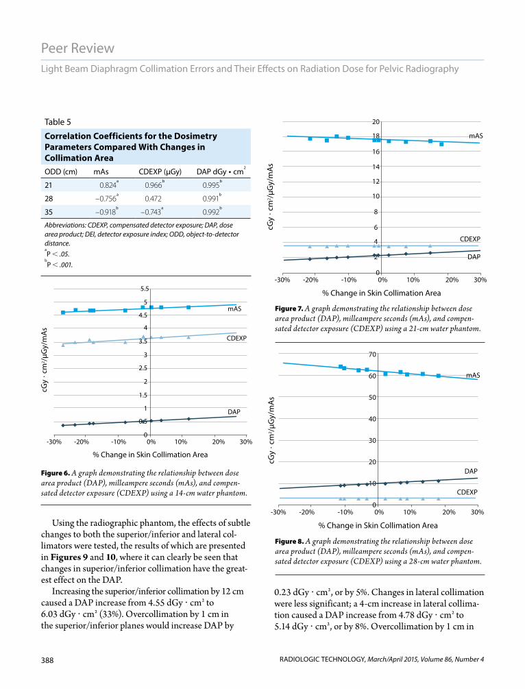
From the data presented (see Table 4), only minor variations in mAs (range, 5%) are shown across dif-ferent actual field sizes. Although the range of mAs values was small (5%), there was a strong positive correlation with increasing field size (see Table 5). CDEXP was similar, with a gradual increase in percentage collimation error or change in field size (range, 4%). DAP increased when increasing the collimated field size by a greater range (37%). The correlation between DAP and increasing field size showed the strongest positive correlation (see Table 5 and Figures 6-8).
Table 4
Changes in mAs, DEI, CDEXP, and DAP Compared With Percent Changes in the Collimated Field Size From 252 cm2a
ODD (cm)
Collimation Error by Irradiated Surface Area (%) mAs DEI
CDEXP (µGy)
DAP (dGy • cm2)
21 –27.4 4.59 0.77 3.44 0.37
–23.3 4.68 0.78 3.5 0.40
–18.7 4.71 0.79 3.55 0.43
–17.7 4.69 0.79 3.54 0.43
–7.7 4.73 0.81 3.61 0.49
–5.5 4.75 0.82 3.66 0.53
0.3 4.83 0.83 3.71 0.55
5.4 4.77 0.83 3.69 0.57
12.0 4.76 0.83 3.72 0.62
28 –21.7 17.84 0.79 3.52 1.86
–16.6 17.64 0.78 3.5 1.89
–13.7 18.07 0.80 3.57 2.06
–10.2 17.92 0.80 3.57 2.14
–2.2 17.62 0.80 3.57 2.29
0.9 17.63 0.80 3.56 2.31
2.2 17.46 0.79 3.53 2.36
7.4 17.37 0.79 3.54 2.48
14.7 17.47 0.80 3.58 2.68
35 –11.3 64.58 0.79 3.52 9.32
–10.2 63.64 0.78 3.5 9.53
–8.6 62.79 0.78 3.47 9.84
–5.9 62.99 0.78 3.49 9.96
2.2 61.17 0.77 3.44 10.33
6.7 61.99 0.78 3.47 10.80
8.7 60.79 0.77 3.43 10.87
13.4 61.12 0.78 3.47 11.29
18.1 60.33 0.77 3.44 11.57
Abbreviations: CDEXP, compensated detector exposure; DAP, dose area product; DEI, detector exposure index.aDEI is displayed in compensated radiation dose at the surface of the detec-
tor, CDEXP is displayed in µGy, and DAP is displayed in dGy • cm2.
388
Peer Review
RADIOLOGIC TECHNOLOGY, March/April 2015, Volume 86, Number 4
Light Beam Diaphragm Collimation Errors and Their Effects on Radiation Dose for Pelvic Radiography
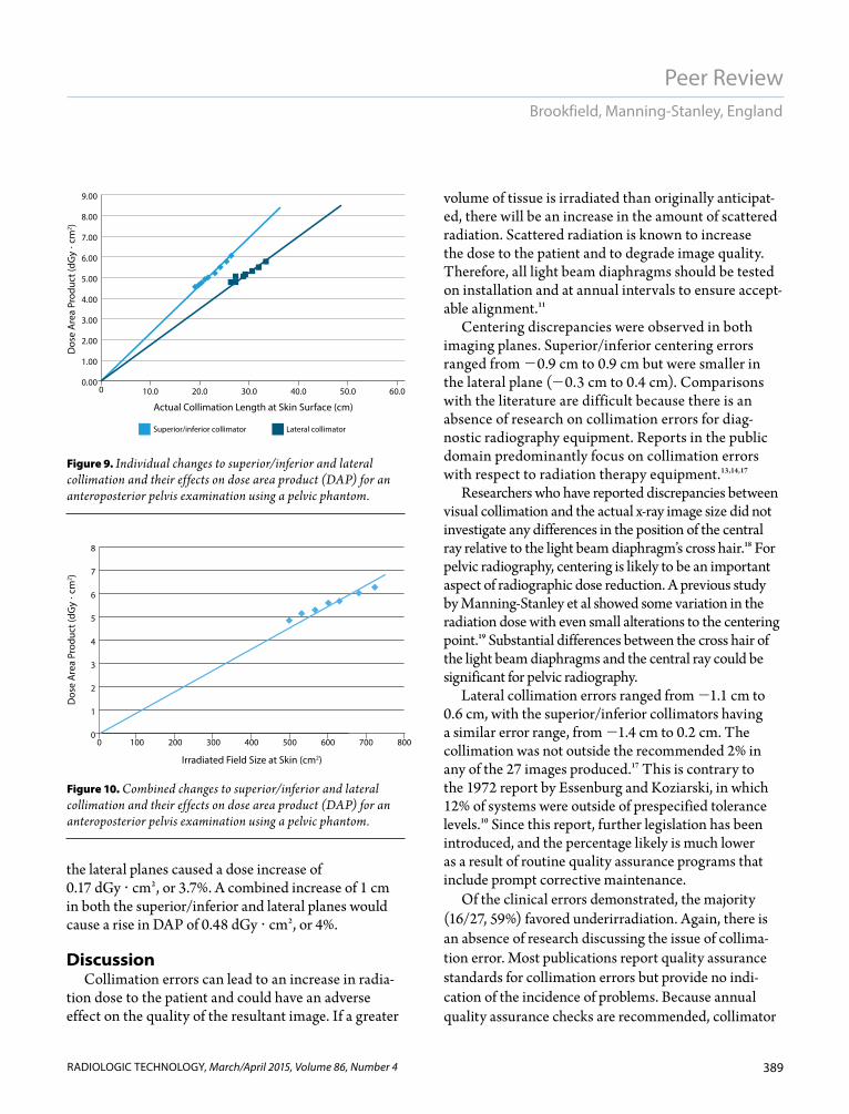
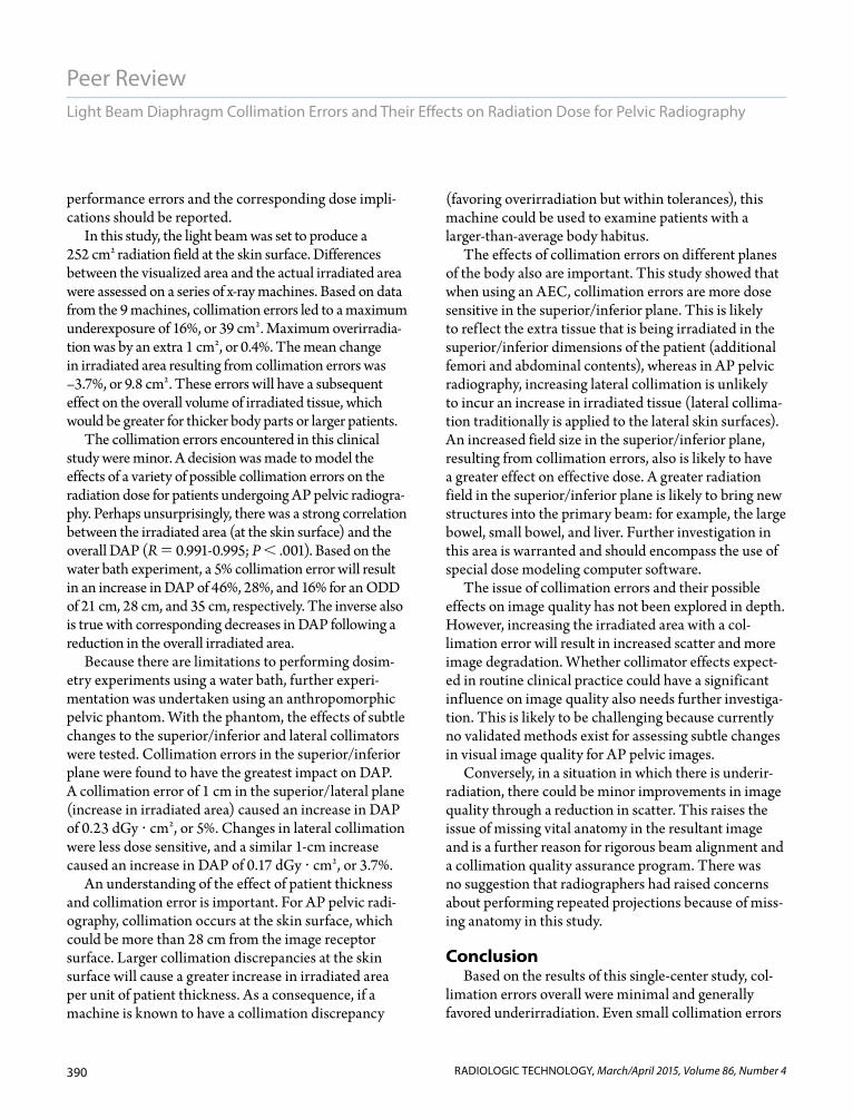
Using the radiographic phantom, the effects of subtle changes to both the superior/inferior and lateral col-limators were tested, the results of which are presented in Figures 9 and 10, where it can clearly be seen that changes in superior/inferior collimation have the great-est effect on the DAP.
Increasing the superior/inferior collimation by 12 cm caused a DAP increase from 4.55 dGy cm2 to 6.03 dGy cm2 (33%). Overcollimation by 1 cm in the superior/inferior planes would increase DAP by
0.23 dGy cm2, or by 5%. Changes in lateral collimation were less significant; a 4-cm increase in lateral collima-tion caused a DAP increase from 4.78 dGy cm2 to 5.14 dGy cm2, or by 8%. Overcollimation by 1 cm in
Table 5
Correlation Coefficients for the Dosimetry Parameters Compared With Changes in Collimation Area ODD (cm) mAs CDEXP (μGy) DAP dGy • cm
2
21 0.824a
0.966b
0.995b
28 –0.756a
0.472 0.991b
35 –0.918b
–0.743a
0.992b
Abbreviations: CDEXP, compensated detector exposure; DAP, dose area product; DEI, detector exposure index; ODD, object-to-detector distance.aP .05.
bP .001.
% Change in Skin Collimation Area
cGy
� cm
2 /µG
y/m
As
CDEXP
DAP
mAS
10% 20% 30%0%0
1
0.5
1.5
2.5
2
4.5
3.5
3
4
5
5.5
-10%-20%-30%
10% 20% 30%0%0
4
2
6
10
8
16
12
14
18
20
-10%-20%-30%
% Change in Skin Collimation Area
CDEXP
DAP
mAS
cGy
� cm
2 /µG
y/m
As
10% 20% 30%0%0
10
20
30
40
50
60
70
-10%-20%-30%
cGy
� cm
2 /µG
y/m
As
% Change in Skin Collimation Area
CDEXP
DAP
mAS
Figure 6. A graph demonstrating the relationship between dose area product (DAP), milleampere seconds (mAs), and compen-sated detector exposure (CDEXP) using a 14-cm water phantom.
Figure 7. A graph demonstrating the relationship between dose area product (DAP), milleampere seconds (mAs), and compen-sated detector exposure (CDEXP) using a 21-cm water phantom.
Figure 8. A graph demonstrating the relationship between dose area product (DAP), milleampere seconds (mAs), and compen-sated detector exposure (CDEXP) using a 28-cm water phantom.
389
Peer Review
RADIOLOGIC TECHNOLOGY, March/April 2015, Volume 86, Number 4
Brookfield, Manning-Stanley, England
the lateral planes caused a dose increase of 0.17 dGy cm2, or 3.7%. A combined increase of 1 cm in both the superior/inferior and lateral planes would cause a rise in DAP of 0.48 dGy cm2, or 4%.
DiscussionCollimation errors can lead to an increase in radia-
tion dose to the patient and could have an adverse effect on the quality of the resultant image. If a greater
volume of tissue is irradiated than originally anticipat-ed, there will be an increase in the amount of scattered radiation. Scattered radiation is known to increase the dose to the patient and to degrade image quality. Therefore, all light beam diaphragms should be tested on installation and at annual intervals to ensure accept-able alignment.11
Centering discrepancies were observed in both imaging planes. Superior/inferior centering errors ranged from 0.9 cm to 0.9 cm but were smaller in the lateral plane (0.3 cm to 0.4 cm). Comparisons with the literature are difficult because there is an absence of research on collimation errors for diag-nostic radiography equipment. Reports in the public domain predominantly focus on collimation errors with respect to radiation therapy equipment.13,14,17
Researchers who have reported discrepancies between visual collimation and the actual x-ray image size did not investigate any differences in the position of the central ray relative to the light beam diaphragm’s cross hair.18 For pelvic radiography, centering is likely to be an important aspect of radiographic dose reduction. A previous study by Manning-Stanley et al showed some variation in the radiation dose with even small alterations to the centering point.19 Substantial differences between the cross hair of the light beam diaphragms and the central ray could be significant for pelvic radiography.
Lateral collimation errors ranged from 1.1 cm to 0.6 cm, with the superior/inferior collimators having a similar error range, from 1.4 cm to 0.2 cm. The collimation was not outside the recommended 2% in any of the 27 images produced.17 This is contrary to the 1972 report by Essenburg and Koziarski, in which 12% of systems were outside of prespecified tolerance levels.10 Since this report, further legislation has been introduced, and the percentage likely is much lower as a result of routine quality assurance programs that include prompt corrective maintenance.
Of the clinical errors demonstrated, the majority (16/27, 59%) favored underirradiation. Again, there is an absence of research discussing the issue of collima-tion error. Most publications report quality assurance standards for collimation errors but provide no indi-cation of the incidence of problems. Because annual quality assurance checks are recommended, collimator
00
1
2
3
4
5
6
7
8
500 600 700 800400300200100
Dos
e A
rea
Prod
uct (
dGy
� cm
2 )
Irradiated Field Size at Skin (cm2)
0.000
1.00
2.00
3.00
4.00
5.00
6.00
7.00
8.00
9.00
50.0 60.040.030.020.010.0
Dos
e A
rea
Prod
uct (
dGy
� cm
2 )
Actual Collimation Length at Skin Surface (cm)
Superior/inferior collimator Lateral collimator
Figure 9. Individual changes to superior/inferior and lateral collimation and their effects on dose area product (DAP) for an anteroposterior pelvis examination using a pelvic phantom.
Figure 10. Combined changes to superior/inferior and lateral collimation and their effects on dose area product (DAP) for an anteroposterior pelvis examination using a pelvic phantom.
390
Peer Review
RADIOLOGIC TECHNOLOGY, March/April 2015, Volume 86, Number 4
Light Beam Diaphragm Collimation Errors and Their Effects on Radiation Dose for Pelvic Radiography
performance errors and the corresponding dose impli-cations should be reported.
In this study, the light beam was set to produce a 252 cm2 radiation field at the skin surface. Differences between the visualized area and the actual irradiated area were assessed on a series of x-ray machines. Based on data from the 9 machines, collimation errors led to a maximum underexposure of 16%, or 39 cm2. Maximum overirradia-tion was by an extra 1 cm2, or 0.4%. The mean change in irradiated area resulting from collimation errors was –3.7%, or 9.8 cm2. These errors will have a subsequent effect on the overall volume of irradiated tissue, which would be greater for thicker body parts or larger patients.
The collimation errors encountered in this clinical study were minor. A decision was made to model the effects of a variety of possible collimation errors on the radiation dose for patients undergoing AP pelvic radiogra-phy. Perhaps unsurprisingly, there was a strong correlation between the irradiated area (at the skin surface) and the overall DAP (R 0.991-0.995; P .001). Based on the water bath experiment, a 5% collimation error will result in an increase in DAP of 46%, 28%, and 16% for an ODD of 21 cm, 28 cm, and 35 cm, respectively. The inverse also is true with corresponding decreases in DAP following a reduction in the overall irradiated area.
Because there are limitations to performing dosim-etry experiments using a water bath, further experi-mentation was undertaken using an anthropomorphic pelvic phantom. With the phantom, the effects of subtle changes to the superior/inferior and lateral collimators were tested. Collimation errors in the superior/inferior plane were found to have the greatest impact on DAP. A collimation error of 1 cm in the superior/lateral plane (increase in irradiated area) caused an increase in DAP of 0.23 dGy cm2, or 5%. Changes in lateral collimation were less dose sensitive, and a similar 1-cm increase caused an increase in DAP of 0.17 dGy cm2, or 3.7%.
An understanding of the effect of patient thickness and collimation error is important. For AP pelvic radi-ography, collimation occurs at the skin surface, which could be more than 28 cm from the image receptor surface. Larger collimation discrepancies at the skin surface will cause a greater increase in irradiated area per unit of patient thickness. As a consequence, if a machine is known to have a collimation discrepancy
(favoring overirradiation but within tolerances), this machine could be used to examine patients with a larger-than-average body habitus.
The effects of collimation errors on different planes of the body also are important. This study showed that when using an AEC, collimation errors are more dose sensitive in the superior/inferior plane. This is likely to reflect the extra tissue that is being irradiated in the superior/inferior dimensions of the patient (additional femori and abdominal contents), whereas in AP pelvic radiography, increasing lateral collimation is unlikely to incur an increase in irradiated tissue (lateral collima-tion traditionally is applied to the lateral skin surfaces). An increased field size in the superior/inferior plane, resulting from collimation errors, also is likely to have a greater effect on effective dose. A greater radiation field in the superior/inferior plane is likely to bring new structures into the primary beam: for example, the large bowel, small bowel, and liver. Further investigation in this area is warranted and should encompass the use of special dose modeling computer software.
The issue of collimation errors and their possible effects on image quality has not been explored in depth. However, increasing the irradiated area with a col-limation error will result in increased scatter and more image degradation. Whether collimator effects expect-ed in routine clinical practice could have a significant influence on image quality also needs further investiga-tion. This is likely to be challenging because currently no validated methods exist for assessing subtle changes in visual image quality for AP pelvic images.
Conversely, in a situation in which there is underir-radiation, there could be minor improvements in image quality through a reduction in scatter. This raises the issue of missing vital anatomy in the resultant image and is a further reason for rigorous beam alignment and a collimation quality assurance program. There was no suggestion that radiographers had raised concerns about performing repeated projections because of miss-ing anatomy in this study.
ConclusionBased on the results of this single-center study, col-
limation errors overall were minimal and generally favored underirradiation. Even small collimation errors
391
Peer Review
RADIOLOGIC TECHNOLOGY, March/April 2015, Volume 86, Number 4
Brookfield, Manning-Stanley, England
can have an effect on DAP and for pelvic radiography are more dose significant in the superior/inferior plane. Regular quality assurance of light beam diaphragms is recommended and can help minimize radiation dose to patients. Collimation errors are confounded by increas-es in patient thickness. The effects of such errors should be of high importance when examining areas where body part thickness is highly variable, such as the pelvis, abdomen, and thoracolumbar spine.
Hannah Brookfield, BSc(Hons), is a band 5 radiographer and a member of the Department of Radiology at Aintree University Hospital NHS Foundation Trust in the United Kingdom. She can be reached at [email protected].
Anthony Manning-Stanley, BSc(Hons), is a radiographer and a member of the Department of Radiology at Salford Royal Hospital NHS Foundation Trust in the United Kingdom. He can be reached at [email protected].
Andrew England, BSc(Hons), PgCert, MSc, PhD, FHEA, is a senior lecturer in radiography and a mem-ber of the Directorate of Radiography at the University of Salford in the United Kingdom. He can be reached at [email protected].
Received January 16, 2014; accepted with revisions February 20, 2014.
Reprint requests may be mailed to the American Society of Radiologic Technologists, Communications Department, at 15000 Central Ave SE, Albuquerque, NM 87123-3909, or e-mailed to [email protected].
© 2015 American Society of Radiologic Technologists
References1. Carter PH. Imaging Science. Oxford, UK: Blackwell Science;
2006:56. 2. Fauber TL. Radiographic Imaging and Exposure. 4th ed. St
Louis, MO: Elsevier Mosby; 2013:121-122.3. Jeffery CD. The effect of collimation of the irradiated field
on objectively measured image contrast. Radiography. 1997;3(3):165-177.
4. Horner K. Review article: radiation protection in dental radi-ology. Br J Radiol. 1994;67(803);1041-1049.
5. White SC, Pharoah MJ. Oral Radiography Principles and Interpretation. 6th ed. St Louis, MO: Mosby; 2009:11.
6. The Ionising Radiations Regulations 1999. London, UK: The Stationary Office; 1999. SI 1999 No 3232.
7. Freeman DK. Testing coincidence of x-ray and light beam. Med Phys. 1984;11(1):78.
8. Voronin KV, Okhrimenki SE. Checking of the automatic col-limation system of the x-ray beams in diagnostic equipment. Med Tekh. 2004;(6):38-39.
9. Moores BM, Henshaw ET, Watkinson SA, Pearcy BJ. Practical Guide to Quality Assurance in Medical Imaging. London, UK: Wiley & Sons; 1987:74.
10. Essenburg A, Koziarski B. Alignment of light-localized beam and radiographic x-ray beam. Radiology. 1972;104(3):716.
11. European Commission. Criteria for Acceptability of Radiological (Including Radiotherapy) and Nuclear Medicine Installations. Brussels, Belgium, Commission of European Communities; 1997. Radiation Protection No 91. http://ec.europa.eu/energy/nuclear/radiation_protection/doc /publication/091_en.pdf
12. Hutchinson DE, Cobb BJ, Jacob CS. A compliance testing program for diagnostic x-ray equipment. Appl Radiat Isot. 1999;50(1):237-245.
13. Ramsey CR, Spencer KM, Alhakeem R, Oliver AL. Leaf position error during conformal dynamic arc and intensity modulated arc treatments. Med Phys. 2001;28(1):67-72.
14. Budgell GJ, Mott JH, Williams PC, Brown KJ. Requirements for leaf position accuracy for dynamic multileaf collimation. Phys Med Biol. 2000;45(5):1211-1227.
15. Hart D, Wall BF, Hillier MC, Shrimpton PC. Frequency and Collective Dose for Medical and Dental X-ray Examinations in the UK, 2008. Health Protection Agency, Centre for Radiation, Chemical and Environmental Hazards. HPA-CRCE-012. 2010.
16. Egbe NO, Chiaghanam NO, Bassey DE, Eshiet EE. Studies on the status of light beam diaphragms in Calabar: effects and implications on radiation protection. West Afr J Radiol. 2003;10(1):34-41.
17. Oliver M, Gagne I, Bush K, Zavgorodni S, Ansbacher W, Becham W. Clinical significance of multi-leaf collimator posi-tional errors for volumetric modulated arc therapy. Radiother Oncol. 2010;97(3):554-560.
18. Conference of Radiation Control Program Directors. Computed radiography (CR) and digital radiography (DR) state x-ray inspection protocol. Publication No. E-10-2. http://www.crcpd.org/Pubs/CR&DR_Protocol.pdf. Published January 2010. Accessed December 4, 2014.
19. Manning-Stanley AS, Ward AJ, England A. Options for radia-tion dose optimisation in pelvic digital radiography: a phan-tom study. Radiography. 2012;18(4):256-263.

Third PrizeTiffany & Co. 9” Rock-cut Bowl
Second PrizeSennheiser HD 380 Pro Headphones
©2015 ASRT Foundation. All rights reserved.
You Win Either Way.Win great prizes. Help R.T.s succeed.
Grand PrizeYour choice of a fi ve-night dream vacationto Las Vegas, San Antonio or Kauai, Hawaii.
A minimum contribution for a ticket is not required to enter or win. ASRT members can obtain information about receiving one complimentary entry by calling 800-444-2778. Complimentary tickets will be processed by mail during normal business hours Monday, February 16, 2015, 8 a.m. Mountain time through Friday, May 29, 2015, 11:59 p.m. Mountain time.
All proceeds from the Annual Drawing go to ASRT Foundation programs that support and empower radiologic science professionals and students.
Only ASRT members are eligible to purchase tickets and claim prizes.
Tickets are only $25.
Buy tickets now at www.asrtfoundation.org/youwin or call 800-444-2778.
ANNUAL DRAWING
FDN15_AnnualDraw_General_BW.indd 1 2/13/15 3:11 PM