Embed Size (px)
Citation preview

LIFEBOAT MANUALBy Lt. Comdr. A. E. Redifer, U.S.M.S.
Lifeboat Training Officer, Avalon, Calif., Training Station
*Indispensable to ordinary seamen preparing for the LifeboatExamination.
*A complete guide for anyone who may have to use a lifeboat.
Construction, equipment, operation of lifeboats and other buoyantapparatus are here, along with the latest Government regulationswhich you need to know.
163 Pages More than 150 illustrations Indexed $2.00
METEOROLOGY WORKBOOK with Problems
By Peter E. KraghtSenior Meteorologist, American Airlines, Inc.
*Embodies author's experience in teaching hundreds of aircraft
flight crews.
*For self-examination and for classroom use.
*For student navigator or meteorologist or weather hobbyist.*A good companion book to Mr. Kraght's Meteorology for Shipand Aircraft Operation, 0r any other standard reference work.
141 Illustrations Cloud form photographs Weather maps148 Pages W$T x tl" Format $2.25
MERCHANT MARBMI OFFICERS' HANDBOOKBy E. A. Turpin and W. A. MacEwen, Master Mariners
"A valuable guide for both new candidates for . . . officer's
license and the older, more experienced officers." Marine Engi-neering and Shipping Re$etu.
An unequalled guide to ship's officers' duties, navigation,
meteorology, shiphandling and cargo, ship construction and sta-
bility, rules of the road, first aid and ship sanitation, and enlist-
ments in the Naval Reserve all in one volume.
03 086

3rd Edition
"This book will be a great help to not
only beginners but to practical navigatingofficers." Harold Kildall, Instructor in
Charge, Navigation School of the Washing-ton Technical Institute,
"Lays bare the mysteries of navigationwith a firm and sure touch . . . should makea secure place for itself." A. F. Loomis in
Yachting.
"Covers the field thoroughly." TbeRudder.
Thousands of students of sea and air
navigation have agreed with this testimonyto the Primer.
They have found that the Primer takes
into account all the stumbling blocks, andmoves progressively from the simple funda-
mentals to the complex problems, coveringeach step clearly.
Astronomy, Time, the Astronomical Tri-
angle, Trigonometry and reliable proceduresfor Position Finding are explained under-
standably*
An added feature of this Third Edition
is the author's own method for determiningmore exact time of transit of any naviga-tional body reducing Dutton's method from
sixteen lines to ten. "You have made quitea contribution," Herbert L. Stone, editor of
Yachting, wrote the author regarding this
new method. It is published here for the
first time*
267 Pages 21 Tables Fully Indexed


Kansas city |||| public library
Books will be issued only
on presentation of library card.
Please report lost cards and
change of residence promptly.
Card holders are responsible for
all books, records, films, pictures
ecked out on their cards.
Primer of Celestial Navigation

Primer of
Celestial Navigation
By John Favill, M.D.Associate Member, U, S. Naval Institute
Navigator, U. S. Power Squadrons
Colonel, Inactive Reserve, U. S. Army
Third Edition
Revised and Enlarged
New York- 1944
Cornell Maritime Press

Copyright, 194O, 1943, 1944, byCornell IVTa/rltime !Press
IDesigpnted t>y Reinnold Frederic GennerCoixxposed., printed and bound In the XJ. S.

AcknowledgmentsFor answering bothersome questions or for helpful sug-
gestions, the author's sincere thanks go to P, V. H. Weems,Lt. Comdr., U. S. Navy (Ret.), Professor Harlan T. Stetson
of the Massachusetts Institute of Technology, Mr. Alfred F.
Loomis, Secretary of "Yachting," and Selwyn A. Anderson,Master Mariner.


Contents
Preface to Third Edition xiii
Introduction xv
Part I: Fundamentals
1. Astronomical 3
2. Time 24
3. The Nautical Almanac 51
4. Altitudes 55
5. The Sextant 61
6. The Compass69
7. The Astronomical Triangle 79
8. Trigonometry 82
9. Logarithms92
Part II: Procedures
10. Introduction to Position Finding 99
11. Latitude 103
12. Longitude and Chronometer Error 1 14
1 3 . Azimuth and Compass Error 117
14. Sumner Lines of Position 123
15. The Saint-Hilaire Method 128
16. Short-Cut Systems 134
17. Special Fixes 141
18. Polar Position Finding 148
19. Identification 155
20. Tabular Summary 157
Part HI: Supplementary
21. The Sailings, Dead Reckoning, and Current 161
22. The Day's Work 180
23. Essential Equipment 182
24. Practical Points 183
25. Navigator's Stars and Planets 196
26. Reference Rules for Book Problems 205
27. Finding G. C. T. and Date 207
28. Abbreviations 209
29. Forms 212
30. Problems 224
Selected Bibliography 259
Index 261

List of Illustrations
1. Declination,
8
2. Excess of One Rotation 13
3. Diagram for General Orientation facing page 1 3
4. Phases of the Moon 18
5. Precession of the Equinoxes 20
6. The Earth's Orbit 23
7. The Solar Year 27
8. Time Diagram 33
9. Time Diagram 33
10. Time Diagram 33
11. Time Diagram 34
12. Time Diagram 34
13. Time Diagram 35
14. Time Diagram 35
15. Time Diagram 36
16. Time Diagram 36
17. Time Diagram 37
18. Relations Between Zone Time and Local Civil
Time 40
19. Zone Time of Mean Sun Noons in Zone 40
20. Time Frame 44
21. The "Opposite-the-Sun" Meridian 45
22. Time Frame and O. S. M. 45
23. Change of Date 46
24. Refraction 57
25. Parallax 58
26. Sextant 61
ix-

27. Sextant Angles 6228. Arc and Vernier Scales 6429. Reading the Sextant 6630. Compass Card 713 1 . The Astronomical Triangle 7932. For Napier's Rules 8733. Angles in the Different Quadrants 8934. The Four Cases of Latitude from Meridian Alti-
tude Observation 10435. Latitude by Phi Prime, Phi Second 1 1 1
36. Longitude by Time Sight 1 1437. Azimuth
^ ng38. Zenith Distance and the Radius of the Circle of
Equal Altitude 12539. The Saint-Hilaire Method 13140. Rules for H. O. 211 13641. Plane Sailing 16342. Middle Latitude Sailing 16643. First Current Problem 17644. Second Current Problem 17845. FixbyH.O.214.D.R. Position 24246. Fix by H. O. 2 1 4. Assumed Position 244

List of Tables
1. The Solar System 4
2. The Brightest Heavenly Bodies 7
3. Declinations of Navigational Stars 17
4. Time 30
5. Calculations of t 36
6. Zone Time 41
7. Compass Errors 74
8. Finding Deviation 75
9. For Magnetic Steer Compass 76
10. Compass Points and Quarter Points 78
1 1 . Finding Parts o the Astronomical Triangle 80
12. Definition of the Trigonometric Functions of
Plane Right Triangles 83
13. Equivalents of the Trigonometric Functions of
One Acute Angle of a Plane Right Tritegl'when Hypotenuse = 1 &P
14. Trigonometric Functions o Any Angle with the
Sign for Each Quadrant 86
15. Equivalent Trigonometric Functions of Anglesin the Different Quadrants 88
16. Examples of Logarithms 96
17. For Correcting Polar Position Lines 152
18. Summary of Methods facing page 157
19. Rules for Time and Angles 206
20. For Finding G. C. T. and Date 208
21. Working Form for Azimuth by H.O. 214 233


Preface to Third Edition
PEARLHARBOR and all its consequences have come
since this Primer's first birthday. Thousands o officer
candidates have taken up with grim determination the
study which to me for years has been a delightful hobby.
In preparing a new edition, the chief problem was
whether to cut to the bone and leave only the bare essen-
tials for practical purposes or to retain what seemed, and
still seems to me, essential for a secure understanding of the
subject.
Pruned down to lines of position only and plotting on
charts or plotting sheets, it is possible to get along without
the following:
Meridian altitudes, reductions to the meridian and ex-
meridian sights for latitude, interval to noon, time of
transit, time of sun on the prime vertical, time-sights for
longitude, sights for determination of chronometer error,
trigonometry, logarithms, much of the sailings, basic
astronomy, and sidereal time. (I realize one need not even
know the meaning of declination in order to use the almanac
andH. O. 2 14 effectively.)
The original purpose of the Primer however was to help
clarify obscurities. It seems to me this can best be done by
a build-up from simple to complex, and by giving some
procedures which, though no longer needed, have been
strong links in the chain leading to present practice. So the
main framework of this book remains unchanged.xiii

xiv Preface to Third Edition
Some omissions and many more additions will, I hope
increase usefulness. While written primarily for surface
work, the principles here given are, of course, basic foi
aerial navigation. No attempt is made to supply detail foi
the latter, which is so adequately covered in Dutton.
I am still convinced that years of custom have made it
more natural and easy to look, in imagination, at this world
and the universe from above the north rather than from
below the south pole. Hence I have retained the style of
diagram in general use until the years 1936-39, when the
leading texts shifted their viewpoint to face Antarctica.
Probably the important thing is to get the habit of using
some time diagram not a particular type.
In this third edition, about twenty-five minor correc-
tions, changes or insertions have been made without
change of page number. An important addition on Si-
dereal Time has been added on page 249 and the author's
new "Uniform Method for More Exact Time of Local
Transit of Any Body'1
will be found on pages 254-258.
Having been found physically ineligible for active duty,
I launch this new Primer with a bold hope that somehow
its influence, however small, will count in the score of ulti-
mate Victory.
J. F.
February, 1944
Chicago, Illinois

Introduction
K1SCUEAT SEA of human beings from a ship in
distress is usually the result of a radio message. One
or more vessels respond by hastening to the locality of the
trouble. Few of us on shore, reading the press accounts
of such a rescue, fail to feel thrilled that the genius of
Marconi has again added to the large total of lives saved in
this way. But I wonder how often it is realized that manycenturies of development of the art and science of naviga-
tion led up to the ability of the master to state the position
of his ship on this globe within a radius of about one mile.
Without this ability, there would be little help in wireless.
The term Navigation covers a number of items. It is
broadly divided into (1) Geo-navigation and (2) Celo-navi-
gation. Geo-navigation includes the methods of locating
the ship's position by earth landmarks or characteristics.
It is subdivided into (a) Piloting, which has to do with
bearings, buoys, lighthouses, soundings, radio beams and
chart study and (b) Dead Reckoning which deals with
methods of estimating the distance covered and point
reached in a given interval by means of compass observa-
tions, log readings, record of engine revolutions and a few
calculations. Celo-navigation or Celestial Navigation is
also called Nautical Astronomy. It is the subject concerned
with position finding away from all landmarks when a
ship is at sea. This is done by sextant observations of the
sun or moon or certain planets or stars, with notation of
XV

xvi Introduction
exact time of each observation and with the aid of the
Nautical Almanac and certain tables.
The professional seaman learns these things as part of
his job and probably gets very tired of their routine prac-
tice. The occasional cruising yachtsman or even he whoseldom leaves land can find the study of navigation a very
fascinating one and may even let it become an absorbing
hobby. Such at any rate has been my happy experience.Some years ago on Cape Cod a friend who had a sextant
helped me take an observation of the sun and worked out
the longitude via Bowditch. I tried to understand the
various steps but could not. Buying a Bowditch I beganto study these matters from the ground up. Many more
books were soon accumulated. A sextant was purchasedand sights were taken over Lake Michigan and worked
out, with gradually increasing accuracy.
Some of the by-products of this activity have been: an
appreciation of the ingenious powers of spherical trigo-
nometry; an interest in astronomy with realization for the
first time that there actually is some reason, for one whois not an astronomer, to know certain of the stars; some
understanding of the various kinds of time-keeping; a
growing taste for sea stories and sea-lore in general; enjoy-ment of that fine magazine, U. S. Naval Institute Pro-
ceedings, and the popular yachting monthlies; the fun
of having a paper on a small overlooked point acceptedand published; correspondence with several men in dif-
ferent continents as a result of this; the diversion of work-
ing out text-book problems; glimpses of the history of
navigation; and, probably most important of all, the

Introduction xvii
mental refreshment of studying and doing something
utterly different from one's professional work.
The following compilation is limited to off-shore posi-
tion finding and so omits all consideration of the subject
of Piloting. It is intended in no way to supplant for the
beginner such splendid texts as Bowditch or Button but
rather to smooth the road to those books, to which fre-
quent reference will be found. I have used new ways in
presenting some of the old subjects. But my main purpose
is to prevent certain confusions which come to the ama-
teur when first attempting this study. The best-known
books are written by men of much learning who often
seem to have forgotten certain stumbling blocks which
they themselves passed long ago. I have done some of my
stumbling quite recently and am now trying to show how
such can be prevented. The student who wishes to learn
a method as quickly as possible and who does not have
internal distress at following rules blindly and knowing
nothing of their origins will have no need of this manual.
But those who enjoy understanding why things are done
and what they mean, and who like to have all important
steps included will, I hope, find in these pages a certain
satisfaction.

I : Fuinclamentals


1. Astronomical
THEPRACTICAL NAVIGATOR makes use of
tain of the so-called heavenly bodies to locate his posi-
tion. These are the sun, the moon, four planets (Venus,Mars, Jupiter, Saturn), and fifty-five stars.
It is vital for a clear understanding of the uses of these
bodies to consider their positions in space and to orient
ourselves. A long story in the history of science lies behind
our present knowledge.
The earth was known to be a sphere in the fourth cen-
tury B. c.
Eudoxus of Cnidos (about 360 B. c.) taught that the sun,
moon and planets all moved around the earth, which was
stationary.Aristarchus of Samos (310-230 B. c.) considered that the
sun and stars were stationary and that the earth revolved
around the sun.
Hipparchus (130 B. c.) preferred and developed the geo-centric system of Eudoxus. However, he invented planeand spherical trigonometry and observed the phenomenonknown as precession, to be described later. He was the
first of the Greeks" to divide the circle into 360 degreesand attempted to determine the positions of places on the
earth by measuring their latitude and longitude.
Ptolemy of Alexandria (127-151 A. D.) expounded the


Astronomical 5
geocentric system so well that it acquired his name and
was held by scholars for fourteen centuries.
Copernicus (1473-1543) wrote a great book developingthe ideas of Aristarchus, then eighteen centuries old, that
the sun was the center of our system, and stationary, with
the earth and planets revolving around it. This book was
published only in time for Copernicus to see a copy on
his deathbed.
Tycho Brahe (1546-1601) observed the planetary mo-
tions with improved instruments and recorded a great
number over many years.
Johann Kepler (1571-1630)vafter years of calculations,
using much of Tycho's data, found the three laws of
planetary motion that bear his name.
Galileo Galilei (1564-1642) was the pioneer of modern
physics. He made the first telescope, discovered the moons
of Jupiter, and proved the conclusions of Copernicus byactual observations.
Isaac Newton (1642-1727) worked out the laws of motion
and gravity. His Principia published in 1687 "marks
perhaps the greatest event in the history of science" (Dam-
pier-Whetham) .
An ellipse is a closed curve such that the sum of the
two distances from any point on 'its circumference to two
points within, called the foci, is always constant and equal
to the major axis of the ellipse.
The solar system consists of a group of bodies all revolv-
ing around the sun. They go counterclockwise if seen
from above the north pole, in ellipses not circles with
the sun at one of the foci of each ellipse. (See Table 1.)

6 Astronomical
Perihelion is the point on a planet's orbit nearest the
sun. It is reached about January 3 for the earth (91,500,000
miles). The earth moves faster along its orbit when nearer
the sun.
Aphelion is the point on a planet's orbit farthest from
the sun. It is reached about July 3 for the earth (94,500,000
miles).
The so-called "fixed stars" lie far away from our solar
system, so far in fact that only very slight shifts can be
found in the positions of the nearer ones when we observe
them from opposite ends of the earth's orbit. Their ownactual motions appear negligible. The nearest fixed star is
Proxima Centauri, 4i/ light years away or 26,000,000,-
000,000 miles. Deneb, a bright star often used in navigation,lies 650 light years away or 3,900,000,000,000,000 miles!
Brightness of bodies is recorded by numbering the
apparent magnitude. From minus quantities through zero
into plus quantities represents diminishing brightness.
Plus sixth magnitude is just visible to the naked eye. Each
magnitude is 2i/ times brighter than the next fainter one.
The brightest heavenly bodies are shown in Table 2.
The Nautical Almanac gives the necessary data for the
exact location of 55 of the brightest stars and less full data
for an additional list of 110 other stars for occasional use.
The earth rotates on its axis daily as well as revolvingin its orbit around the sun in a year. The earth's axis of
rotation is inclined to the plane of the earth's orbit at
about 661/ degrees and the north pole points approxi-
mately toward the north star or Polaris. The plane of the
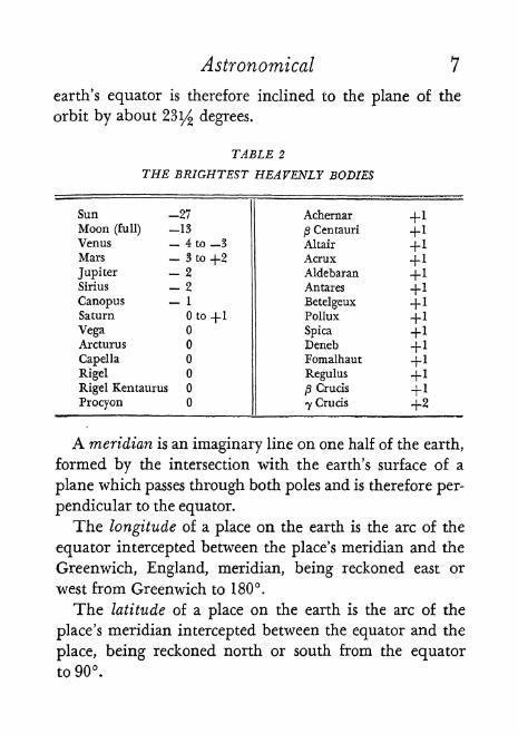
Astronomical 7
earth's equator is therefore inclined to the plane of the
orbit by about 23i/ degrees.
TABLE 2
THE BRIGHTEST HEAVENLY BODIES
A meridian is an imaginary line on one half of the earth,
formed by the intersection with the earth's surface of a
plane which passes through both poles and is therefore per-
pendicular to the equator.
The longitude of a place on the earth is the arc of the
equator intercepted between the place's meridian and the
Greenwich, England, meridian, being reckoned east or
west from Greenwich to 180.
The latitude of a place on the earth is the arc of the
place's meridian intercepted between the equator and the
place, being reckoned north or south from the equatorto 90.

s2T *
* H-J i=
S I
'* s =, IO C3i I
*-J Cj
^ 51 o=
55 r~ a.

Astronomical 9
A parallel of latitude is an imaginary circle formed bythe intersection with the earth's surface of a plane passed
parallel to the plane of the equator.
Declination is one of the most important things to un-
derstand in navigation. It is the angle that a line from
the center of the earth to a given heavenly body makes
with the plane of the earth's equator. Remember it has
nothing to do with where you are on the earth. It is de-
scribed as north or south in reference to the plane of the
equator. The declinations of the stars change very little in
the course of a year. There are great changes however in
the declinations of the sun, moon, and planets.
Equinoxes. As the earth travels around the sun from
winter to summer, the (extended) plane of the equator
approaches nearer and nearer the sun finally cutting its
center at an instant known as the Spring or Vernal equi-
nox on March 21. The plane passes through the sun and
beyond till the earth turns back in its swing around the
sun when the process is repeated through the Fall or
Autumnal equinox on September 23 and so on to win-
ter. The days and nights are equal at the equinoxes except
at the poles. The sun's declination is then zero and it
"rises" in exact east and "sets" in exact west. (See FIG. 1.)
Solstices. There are two instants in the earth's journeyaround its orbit when the sun attains its highest declina-
tion north or south. They are designated Summer solstice
and Winter solstice according to the season in the north-
ern hemisphere, and occur June 21 and December 22,
respectively.
Celestial Sphere. Declination alone is not enough to
locate a body in the sky. We require some means of regis-

10 Astronomical
tering its east or west position as well as its north or south.
For this purpose we imagine a great hollow "celestial"
sphere to lie outside our universe with the earth at its
center. The heavenly bodies can be projected onto the
inner surface of this sphere as can also the plane of the
earth's equator, or any meridian or point on the earth as
though observed from the earth's center. Likewise the posi-
tion of the sun's center at the time of the Vernal equinoxon March 21 as seen from the earth can be projected. This
point is also called the Vernal equinox or ''First Point of
Aries." Its symbol isT. It is taken as the zero of measure-
ment around the celestial equator or equinoctial which is
the projection of the earth's equator. The extension of
the plane of the earth's orbit to the celestial sphere pro-duces a circle on the latter known as the ecliptic. Thetwo points where the equinoctial and ecliptic intersect
mark the two equinoxes. The angle of about 231/
of
these intersections measures the obliquity of the ecliptic.
Right Ascension is a measure of angular distance around
the celestial equator, eastward from T . It is expressed in
hours (and minutes and seconds) up to 24. By giving a
body's declination and right ascension, we pin it down to
a definite location on the celestial sphere just as a place onearth is fixed by giving its latitude and longitude. Thedeclination corresponds to the parallel of latitude andthe right ascension to the meridian of longitude. We will
see later that the R. A. of the projected local meridian
equals the local sidereal time and 24 hours of sidereal
time measure practically one exact rotation of the earth.

Astronomical 1 1
Translating time to arc we have:
24 h = 360
1 h = 15
4m= 1
1 m = 15'
4 s = 1'
1 s = 15"
Speaking in terms of apparent motion, we could say a
body's R. A. is the distance (angle or hour) at which it is
trailing the T in the latter's journey around the equi-
noctial.
The importance of correctly orienting ourselves in rela-
tion to solar system and stars and their real and apparent
motions and our real motion cannot be overstated. Much
of the bewilderment of the beginner comes from encoun-
tering emphasis on apparent motion with inadequate ex-
planation of the real situation. For instance, "the sun's
path among the stars" is a most confusing expression. It
would be plain if we could see stars in the daytime and
would compare the sun's position at a certain time on two
successive days. Then we would observe the shift to the
eastward which is meant. It is just as though we were in a
train going forward and, looking out a window on the
left side, observed a tree 200 yards away and a bit of
woods 2,000 yards away and immediately shut our eyes
(passage of 24 h) and quickly looked again. The nearby
tree (sun) then seems to have moved to the left in relation

12 Astronomical
to the distant trees (stars). Another expression, the "re-
volving dome" of the celestial sphere, is also misleading.
Remember our earth is rotating to the east. The celestial
sphere therefore only seems to rotate to the west. In north
latitudes we see the north star as though it were a pin or
hub on the inside of a sphere which turns around it counter-
clockwise. Bodies are swinging over it to the left and
returning under it to the right.
Another extremely important fact to realize is this: the
earth because of its progress around its orbit must makea little more than one exact rotation between two succes-
sive noons. From Monday, at the instant the sun is due
south in the northern hemisphere, till Tuesday, when the
sun is again due south, there has been something over
one complete rotation of the earth. It is incorrect to ex-
plain this by saying the sun has shifted somewhat to the
east. The truth is that the progress of the earth in its orbit
at a speed of 30 kilometers per second has altered the
direction of the earth from the sun. This makes the sun
seen from the earth appear to have shifted eastward. This
will explain why a true sun day is a longer bit of time
than a star day which requires practically only one exact
rotation. (See FIG. 2.) Owing to the eccentricity of the
earth's orbit and obliquity of the ecliptic these sun days
are not exactly equal.
At this point the student may profit by inspection of
Figure 3, a diagram designed to make more clear some of
the matters so far discussed. The following explanation of
the diagram should be carefully studied.

Astronomical 13
MARCH
DECEMBER
FIG. 2. Excess of One Rotation.
Earth's gain of V* of a rotation when 14 around Orbit. Line on Earth =
Meridian of some place, say Greenwich, at Noon in each instance.
Explanation o Diagram
Outer circumference represents the celestial sphere in the
plane of its equator seen from north.
p at top is "First Point of Aries" from which right ascension
is counted in a circle divided into 24 hours, numbered counter-

14 Astronomical
clockwise. These are shown in the 2nd band. Right ascension
on the celestial sphere is similar to longitude on the earth.
Decimation on the celestial sphere corresponds to latitude onthe earth but cannot be shown here in the one plane.
Fifty-five navigational stars including Polaris whose rightascensions and declinations change very little are shown in
the outer band in approximately correct positions. Those with
a minus sign added are o southern declination and lie below
(behind) the diagram while all others are of northern declina-
tion above (in front of) the diagram. These are the stars for
which complete data are given in the Nautical Almanac andwhich are most easily used for position finding.
The 12 "Signs of the Zodiac" are included in the 3rd bandfor popular interest only. They are named from various con-
stellations of stars which lie in a belt not over 8 above andbelow the plane of the earth's orbit, or the ecliptic on the
celestial sphere. Because of the slow swing of the north end of
the earth's axis in a circle around the north pole of'the ecliptic,
clockwise if seen from above, once in 26,000 years, the equi-noxes (points) gradually shift to the westward. Hence the Springor Vernal equinox (T)> which when named about 2,100 yearr,
ago was actually in the sign of Aries, is now almost throughPisces. Note that this point T on the celestial sphere is where
the sun seems to be when seen from the earth on the 21st ol
March. At that time (also known as the Spring or Vernal equi
nox) the sun's declination is changing from south to north
Dotted lines show this date and also the dates of the Fall equi-
nox, the Summer solstice and the Winter solstice.
The 4th band of months is for locating the earth in its orbit.
The five circles outside the sun as labeled are for the orbits
of the earth and the four planets used in navigation, with their
periods of rotation, all counterclockwise.
The "spokes" are to show two-hourly intervals of R. A.


iS'o*
T t
station.

Astronomical 15
How to Use DiagramMake a dot on earth's orbit corresponding to the date.
Look in N. A. for R. A. of each of the planets for the same
date and make a dot on each orbital circle at the given R. A.
Look in N. A. for moon's R. A. for the same date and time
and make a dot near earth corresponding to this.
Turn diagram till sun and earth are in a line "across the
page" with sun on the right.
Lay a ruler across diagram edge up so edge passes throughsun and earth.
All above ruler edge represents stars and planets available
around evening twilight of day in question at equator.
Holding diagram stationary, rotate ruler edge counter-
clockwise with earth as center, through 90. All to left of ruler
edge represents sky of midnight at equator.
Similarly rotate ruler edge counterclockwise with earth as
center through another 90. All below ruler edge represents
sky of twilight next morning at equator.If position of observer were at one of the poles, all stars and
planets with the corresponding declination would be visible
during the six months of darkness while those of oppositedecimation would be invisible.
As position of observer increases in latitude from equator
to, say, the north pole, the visible stars of southern declination
will diminish in number, beginning with the highest declina-
tions, while the visible stars of northern declination will in-
crease in number, also beginning with the highest declinations.
Note: This diagram is of course not to scale and only an approximation.Remember the planet dots do not represent exact positions of planets
in their orbits but rather the planets' positions on the celestial sphere as
seen from earth and expressed in R. A. The earth's journey around its
orbit accordingly results in apparent retrograde movement of planets at
times. (Jupiter, 1937: Jan. 1, R. A. 18* 29**; May 1, R. A. 19^ 56m; Octo-
ber 1, R. A. 19*> 18m; December 1, R. A. 19* 52m.)

16 Astronomical
The orbits are in reality ellipses with the sun at one focus and not circles
as here given.The plane of the earth's orbit, near which the Zodiac signs are
grouped, and the plane of the earth's equator, along which the R. A.
hours are measured, actually lie 2$V2 degrees apart but are here supposedto be compressed into the plane of the diagram. Likewise the planes of
the planets* orbits are leveled into the diagram. The months are here
marked as though of uniform length. Periods of rotation are approximate.
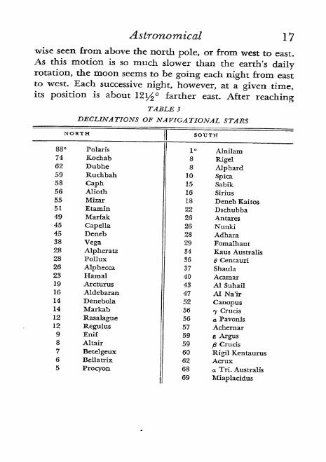
In order to show how far above and below the previous
diagram the various stars lie, a list of declinations is pro-
vided. It shows the order the stars would be met with from
the north pole to the south pole of the celestial sphere
(See Table 3.)
A chart in the back of the Nautical Almanac combines
data from the preceding diagram and list (R. A. and Dec.)in one plane. It is of the Mercator type (which will be
explained later) and so is somewhat confusing to the
beginner.
A celestial globe is a great help in learning star loca-
tions, constellations, etc. The only difficulty is that it shows
the celestial sphere from without and one must always
imagine a given group as seen from the center of the globein order to duplicate the actual group in the sky.
The moon's motion and "phases" deserve some atten-
tion here. The moon is about 238,840 miles away. It
rotates on its axis only once, counterclockwise from above,
in its trip of revolution around the earth; hence it always
keeps the same face toward us. It makes a complete revo-
lution judged by its relation to stars in 27 1/3 days but to
completely circle the earth (which is traveling in its orbit)
requires 291/ days. It is cold and only shines by light
from the sun. It revolves around the earth counterclock-
Astronomical 17
wise seen from above the north pole, or from west to east.As this motion is so much slower than the earth's dailyrotation, the moon seems to be going each night from eastto west. Each successive night, however, at a given time,its position is about 12i^ farther east. After reaching
TABLE 3
DECLINATIONS OF NAVIGATIONAL STARS

18 Astronomical
"full" it "rises" about 50 minutes later each evening. Pre-
vious to full it may be seen as early as mid-afternoon and
subsequent to full it may be seen up to several hours after
sunrise or even till noon.
As the plane of the moon's orbit is near the plane of the
earth's, the moon will appear to observers in the northern
hemisphere lower in the southern sky in summer and higher<t i>
HALFLf\5T QUARTER
o
o
"FULL*
"HALF*1s1 QUARTER
FIG. 4. Phases of the Moon.
Diagram is from above North Pole of Earth. Outer row shows how each
position appears in our North Latitudes. The small projection from theMoon is a fixed point and shows that the same face remains toward the Earth.

Astronomical 19
in winter. This will be understood if Figure 1 is now re-
viewed. Figure 4 will explain the moon's phases.
Miscellaneous Facts
Precession of the Equinoxes. Each year the equinoxes
(Spring and Fall) come about 20 minutes sooner. An equi-
nox can either be thought of as a certain instant in the
earth's journey around its orbit>when the plane of the
equator cuts the center of the sun, or as the point on the
celestial sphere where the sun appears to be at that time, as it
is changing from S. to N. or from N. to S. declination.
These points are shifting to the west, or in a direction op-
posite to the earth's orbital motion. They do so about 50"
of arc on the celestial sphere per year.
This all happens because the extended ends of the earth's
axis are very slowly making circular motions around the
poles of the ecliptic. (Disregard the ellipses which the axis
makes in one year because at the distance of the celestial
sphere these ellipses would be extremely small.) The projec-
tion of the earth's north pole describes a circle with a radius
of about 2 3 1/ around the north pole of the ecliptic, coun-
terclockwise as we look up at it, clockwise as seen from out-
side celestial sphere looking down, once in 26,000 years. The
plane of the earth's equator, perpendicular to the axis, must
likewise shift and, when meeting the sun's center at equi-
nox, will be intersecting the track of the earth's orbit on
each side at a point slightly more westward. This may be
represented (see FIG. 5) by a metal circular ring (plane of
earth's orbit) with a disc (plane of earth's equator) slightly
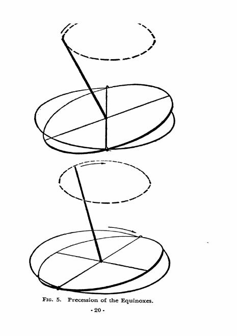
FIG. 5. Precession of the Equinoxes.
-20-

Astronomical 21
smaller inside the ring and loosely attached at two opposite
points (equinoxes) and inclined 23i/ to the ring (obliquityof ecliptic). A rod projects up from the disc's center (parallel
to earth's axis). Shifting the attachments clockwise when
looking down at disc will show rod's tip describing a circle
clockwise around a point above center of ring (north poleof ecliptic). The rod is placed in center instead of at edge
by earth's orbit because it shows the effect more clearly and
because the misplacement is negligible when consideringthe extreme distance of the celestial north pole.
The Vernal equinox (T) called "First Point of Aries"
was in that constellation when named about 2,100 years
ago but has now shifted westward almost through the next
constellation "Pisces."
As a result of this performance, there is a succession of
stars called north stars through the centuries. Our present
one, Polaris, is therefore only playing a temporary role,
The series is as follows:
Vega 12,000s. c.
fiHercules 7,200
Thuban 3,000
Polaris 2, 100 A. D.
Er Rai 4,200
Alderamin 7,500
SCygni 11,500
Vega 14,000
etc.
Another result of precession is that there is a slow in-
crease in the right ascensions of all stars. Naturally, if the

22 Astronomical
starting point for measurement (T) is moving west and the
measurements are made to the east, these measurements
will grow larger.
The north pole of the ecliptic is at R. A, 18, Dec. 661^N. and the south pole at R. A. 6, Dec. 66i/ S.
It may be wondered why the hottest part of northern
summer is not halfway between Spring and Fall equinoxat June 21 and the coldest part of winter at December 22.
The explanation is probably that extra time is required to
warm up the earth in summer and to cool it off as winter
approaches.Earth's perihelion, the position nearest sun, occurring in
northern winter and southern summer, and aphelion, the
position farthest from sun, occurring in northern summer-
and southern winter, might lead one to expect the southern
hemisphere to show more extremes of climate, hotter in
summer and colder in winter. However, the eccentricity
of the orbit is so slight that no great difference is noted.
The eccentricity of an ellipse is expressed by the followingratio:
Distance from center to one focus
Distance from center to one end of major axis'
For the earth's orbit, this is only about y$Q, so the orbit
is not far from circular. Nevertheless, it is 186 days from
Spring to Fall equinox, and only 179 days from Fall to
Spring equinox. The sun therefore is in that focus which is
nearer to us in December and farther from us in June.
(See FIG.6.)
All the planet's orbits lie within 8 of the ecliptic and the
four navigational planets lie within 3.Prof. Dayton C. Miller reported (Science, June 16, 1933)

Astronomical 23
after very exhaustive observations on the speed of light, that
the entire solar system was moving as a body through spaceat a speed of 208 kilometers per second toward a point in
R. A. 4h 56m, Dec. 70 30' S. This is close to the south poleof the ecliptic and about 20 south of the second brightest
star, Canopus.
FALL LQUINOX &LPT ta
VflNTE-R SOLSTICE/-DLC. 2.Z
PE.RWEUON* JAN. 3
FIG. 6. The Earth's Orbit. From Above.
(True eccentricity is even less than here.)
Kepler's Laws are as follows:
1. The orbit of every planet is an ellipse, having the sun
at one of its foci.
2. If a line is supposed to be drawn from the sun to any
planet, this line passes over equal areas in equal times.
3. The squares of the times of revolution about the sun
of any two planets are proportional to the cubes of their
mean distances from the sun.

2 a Time
THESUBJECT OF TIME is one of the tough spots in
the study o navigation. This is partly because new
ways of thinking about time are required and partly because
the explanations are often inadequate. We will try now to
proceed carefully and put in all the steps so that there maybe no misunderstanding.
Apparent Time. We think of time as somehow measured
by the apparent movement of the sun each 24 hour dayaround the earth, caused of course by the earth's rotation
with the sun stationary,
We have seen in Chapter 1 that, while the earth rotates
on its axis at a uniform speed, it does not travel in its orbit
around the sun at a uniform speed. Its speed is faster whencloser to the sun in the elliptical orbit. We also saw that,
because of progress along its orbit, the earth must makesomewhat more than a complete rotation on its axis in order
to bring the sun from a meridian one day back to the same
meridian the next day. Finally, we noted the obliquity of
the ecliptic.
So days measured by sun noons are not uniform because:
(a) The varying speed of the earth in its orbit varies
the necessary daily excess over one revolution, and,
(b) As the plane of the earth's orbit in which the sun
appears to move, does not coincide with the plane of the
earth's equator along which movement is measured, equaldivisions of the former do not make equal divisions of the
latter when projected onto it.
-24-

Time 25
No clock can be made to keep step with this true solar
or, as it is called in navigation, apparent time. Its day be-
gins at midnight. Greenwich (England) apparent time and
local apparent time are designated respectively G. A. T.
and L, A. T.
Mean Time. An imaginary or "mean" sun is therefore
utilized which crosses a given meridian at uniform intervals
throughout the year. The interval is the average of the
true sun days. The mean sun is thought of as in the planeof the earth's equator all the time. The total of days in
the year is the same as for apparent time. Days are divided
into 24 hours of 60 minutes each and each minute into
60 seconds. This is the time our regular clocks keep. In
navigation, the hours are numbered from to 24. Shipchronometers are set to keep Greenwich time and almanacs
give data for this. It is called Greenwich civil (or Green-
wich mean) time (G. C. T. or G. M. T.). The civil time
day begins at midnight. Local civil time is designatedL. C. T.
The Equation of Time is the amount (up to 16 minutes)*
varying from minute to minute of the day and throughthe year, which must be added to or subtracted from appar-ent time to give civil time and vice versa. The N. A. gives
it for every 2 hours with plus or minus sign indicating
procedure for converting civil to apparent time.
Transit of a body occurs the instant its point in the celes-
tial sphere is on the meridian of the observer or on the
meridian 180 away. When the transit is over the meridian
which contains the zenith, it is designated as upper; whenover the meridian 180 away, as lower.

26 Time
Sidereal or Star Time. This is measured by the apparent
daily motion of the Spring equinox or "First Point of
Aries" (T) around the earth. As this point is not marked by
any heavenly body, we are dependent on the astronomers
to calculate its position and publish in almanacs the right
ascensions of bodies measured eastward from it.
"The equinox itself cannot be observed, being merelythe intersection of two abstract lines upon the sky; but by a
very long chain of observations, going back continuouslyto Hipparchus 150 B. c., and earlier, the relative spacing
on the sky of all the lucid stars, and a great many more,
has been determined with continually increasing accuracy,
together with the 'proper motion7
belonging to each. Rela-
tive to this mass of material, the position of the equator and
ecliptic are assigned, or what comes to the same thing, the
coordinates of each star are given relative to the equinoxand equator." (Encyclopedia Britannica, 14th ed., Vol. 22,
p. 227, "Time Measurement/')A further difficulty comes from the constant slow west-
ward shift or precession of the equinox. This is oppositeto the movement of the earth in its orbit and amounts to
50" of arc on the celestial sphere per year, and shortens the
year by about 20 minutes. (For this we do not use the table
given in Chapter 1 under Right Ascension which matches
24 hours with 360 because here we are figuring on a whole
year for 360.)*The year, then, from one equinox and back to the same
* Now 360 = 1,296,000 seconds of arc And 365 days = 525,600 minutesof time. So to show the time which the year loses by this 50" shift:
50" : 1,296,000" :: Xm : 525,600*
1,296,000 X = 26,280,000
X = 20m -K

Time 27
is 20 minutes shorter than the year from a certain position
relative to a "fixed" star and back to the same. These two
kinds of years are known respectively as Solar or Tropical
(equinox to same) and Sidereal (star to same).
OF T
FIG. 7. The Solar Year.
The Solar Year equals an incomplete revolution of the Earth because of
the westward shift of the Vernal Equinox (<][>).
The solar year has: 365.2422 civil days, or 366.2422 side-
real days.
The sidereal year has: 365.25636 civil days, or 366.25636
sidereal days.
The solar year is the more satisfactory for calendar pur-
poses since it keeps the seasons in a constant relation to
dates. It is the one used in general and in the N. A.
The .2422 fractional day of the solar year (just under 14)
28 Time
is what leads to our leap year system. To add a day to the
calendar every 4 years gradually amounts to too much. So
every year, whose number is divisible by 4, is a leap year,
excepting the last year of each century (1900, for example)which is' a leap year only when the number of the centuryis divisible by 4. This keeps the calendar in almost perfect
order.
The matter of the two kinds of year is brought up to
help prevent confusion which may arise from the fact that
Bowditch (1938, p. 146) refers only to the sidereal year, and
Button (7th ed. 1942, p. 248) only to the solar or tropical
year.
Remember, then, that in navigation, whether using civil
or sidereal time, it is always part of a solar year not of a
sidereal. (See FIG. 7.)
The sidereal day is almost exactly the time of one com-
plete rotation of the earth on its axis.* These days are
practically uniform. The sidereal day at any meridian beginswith the transit of the "First Point of Aries'* (T) over that
meridian. The date is usually not used but sidereal time is
spoken of as of a certain date and hour of G. C. T.
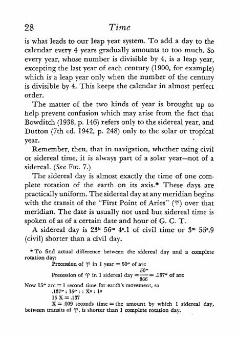
A sidereal day is 23h 56m 4s. 1 of civil time or 3m 558
.9
(civil) shorter than a civil day.
*To find actual difference between the sidereal day and a completerotation day:
Precession of <> in 1 year = 50" of arc
50"Precession of <p in 1 sidereal day = = .137" of arc
Now 15" arc = 1 second time for earth's movement, so
.137" : 15" : : Xs : Is
15X = .137
X = .009 seconds time = the amount by which 1 sidereal day,between transits of "^p, is shorter than 1 complete rotation day.

Time 29
A civil day is 24h 3m 56 S.6 of sidereal time or 3m 56S.6
(sidereal) longer than a sidereal day.
It will be seen that the difference between the shorter
sidereal day and the longer civil day is 3m 55s-9 in civil or
3m 56S.6 in siderealthe sidereal quantity being larger by.7 sec.
The actual lapse of time of this difference is the same,
however expressed. But the sidereal units days, hours,
minutes, seconds are all shorter than similar civil units,
so that for any time interval below the year, measurement
in sidereal units will always show a larger quantity than
measurement in civil units.
Remember there are two senses in which both civil and
sidereal quantities may be interpreted, as follows:
Civil (a) Angular distance of mean sun from lower
transit; and (b) A lapse of time since mean sun made lower
.transit.
Sidereal (a) Angular distance of T from upper transit;
and (b) A lapse of time since T made upper transit.
Now civil and sidereal time in the "a" sense are in similar
units and can be combined without conversion.
But civil and sidereal time in the "b" sense are expres-
sions of duration in different units and cannot be combined
to find sum or difference without converting one into terms
of the other. (N. A. supplies tables to use in convertingeither way.)
Of course an "a" sense of one kind cannot be combined
with a "b" sense of the other.
Apparent Time is found in navigation by sextant obser-
vation of the sun and calculation therefrom of its hour

2CO
-12CO
II
"8 -S z T!^ Q 03 r-Jtf 2 a g
1 s ^~ cr< f?
p
CMCMCMCT>COCO -CJ
cu
a .aO CQ
S"S
-3 S S g^ 2 S & 3
cu rt
ean
or
Civ
s nr 5.
un
&-oI -S
ma
ItJ ^o 3
It^Q
p>^ctJ
ndCM
3? ..CM >-.
xo Z~** ^*& Vi ^cico cd cu
If "o .S3,JQ
1
S CCU
>*
<; co
eter
co
O cj
ae -s QJ
ts
rate
a
oCO
o
S:
S Cg 6
-S^S
cd^CM
? XO
^ '& tjg -S-S
'S ^SG
cu
s Q Q
&to*Hj
.a,pictf
Crf
ig
!
30-
Time 31
angle (to be explained later) or by conversion of civil time
by the equation of time.
Civil Time is not directly observable but is obtained byconversion of either apparent or sidereal. Practically it is
taken from the ship's chronometer, corrected by the knownrate of change of the chronometer or by radio time signals.
Sidereal Time is found by sextant observation of moon,
planet or star, and calculation therefrom of the body's hour
angle which is then combined with its R. A. obtained from
the N. A. It may also be obtained by conversion of civil andsometimes is taken from a sidereal chronometer.
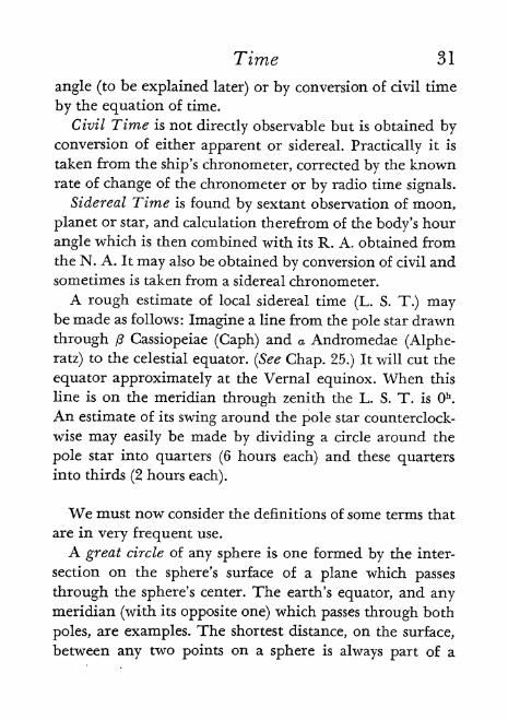
A rough estimate of local sidereal time (L. S. T.) maybe made as follows: Imagine a line from the pole star drawn
through fi Cassiopeiae (Caph) and a Andromedae (Alphe-
ratz) to the celestial equator. (See Chap. 25.) It will cut the
equator approximately at the Vernal equinox. When this
line is on the meridian through zenith the L. S. T. is Oh.
An estimate of its swing around the pole star counterclock-
wise may easily be made by dividing a circle around the
pole star into quarters (6 hours each) and these quartersinto thirds (2 hours each).
We must now consider the definitions of some terms that
are in very frequent use.
A great circle of any sphere is one formed by the inter-
section on the sphere's surface of a plane which passes
through the sphere's center. The earth's equator, and anymeridian (with its opposite one) which passes through both
poles, are examples. The shortest distance, on the surface,
between any two points on a sphere is always part of a
32 Time
great circle. The equinoctial is the great circle on the
celestial sphere produced by intersection of the plane of the
earth's equator. The ecliptic is another.
A small circle of a sphere is one described by the inter-
section on the sphere's surface of a plane which passes
through the sphere but not through its center. All the
parallels of latitude above and below the equator are small
circles. Any circle on a sphere which includes less than half
the sphere is a small circle.
An hour circle is a great circle on the celestial sphere
passing through the poles and some point in question such
as the projection of Greenwich or the projection of a
heavenly body, as seen from the earth's center.
The hour angle of a body is the angle at the pole of the
celestial sphere between the hour circle of the body and
the celestial meridian of the observer. It is also measured
by the arc of the celestial equator between the hour circle
and the celestial meridian. It is either reckoned positively
to the west all around to 360 or 24 hours, or, if over 180
west, is subtracted from 360 and designated east.
Greenwich hour angle is designated G. H. A. and local
hour angle L. H. A. It is becoming customary to limit the
use of L* H. A. to any westward measurement and to use t
for an eastward or westward angle below 180, which is
then known as a meridian angle.
Table 4 may now be studied to review the three kinds
of time.
Diagrams are most useful in visualizing problems in time
or in position finding. It is much easier to record apparentmovements of heavenly bodies on the edge of a circle clock-

Time
Figure 8. A circle represents the celestial sphere in the plane of its equatorand seen from above its north pole. A dot in the center represents earth.
(We use a similar dot and circle to represent the earth and the plane of a
given meridian of the C. S. when working latitude problems.) The circle, of
course, stands for 360 or 24 hours. A line is drawn to the bottom part to
indicate a projection of part of the meridian of the observer and alwayslabeled M.
Figure 9. Another line is drawn as a projection of the meridian of Green-wich. It is placed approximately according to the supposed longitude andlabeled G. Here it shows observer at about longitude 60 W.
FIG. 10
Figure 10- Other lines represent hour circles of heavenly bodies as indicated
with symbols. One of them is filled in after an observation has been madeand the local hour angle has been calculated, as will be explained later. Wemay here recall once more that M, G, and the central dot are really in
counterclockwise motion while any line for a heavenly body is in apparentclockwise motion.

Time
wise, with stationary earth in center, than to record the
actual rotation of the earth at the center of the circle coun-
terclockwise. A simple convention has therefore been
worked out. It may be done free-hand and only approxi-
mately but will show relationships clearly if we rememberthat the clockwise movement is only apparent.
Examples of the chief uses of such diagrams will be seen
in Figures 8 to 17.
Figure II. The "First Point of Aries" (<f) or starting point of sidereal time
may be similarly drawn in problems involving moon, planet or star. TheGreenwich sidereal time would have to be first calculated. The N. A. givesit for Ok G, C. T. of any date. Adding to this the actual G. C. T., and alsoa small amount from a table representing excess of sidereal over civil
during that civil interval, gives G. S. T.
Figure 12 shows G. C. T., G. S. T., and R. A. of a star. Dotted line repre-sents opposite meridian needed for start of G. C, T. Curved lines witharrows show amounts approximately as follows:
G. C, T.G. S. T.
R.A.
Long. W.
(2 P. M.)
60* (4 h.)
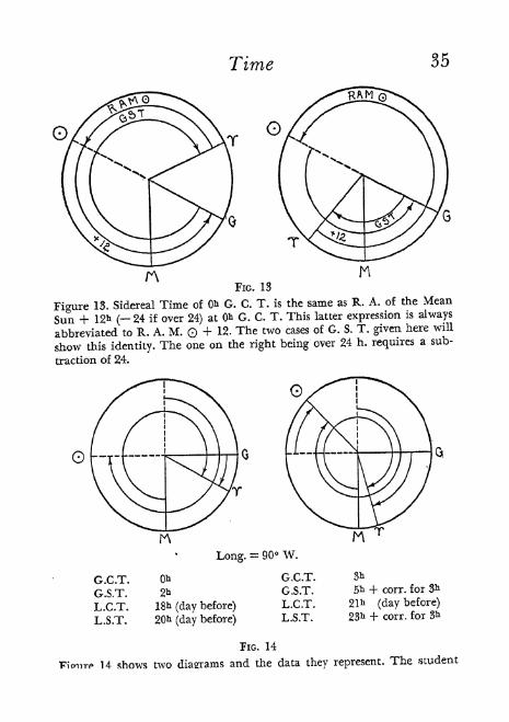
FIG. 13
Figure 13. Sidereal Time of 0& G. C. T. is the same as R. A. of the Mean
Sun + 12* ( 24 if over 24) at 0* G. C. T. This latter expression isalways
abbreviated to R. A. M. Q + 12. The two cases of G. S. T. given here will
show this identity. The one on the right being over 24 h. requires a sub-
traction of 24.
Long.= 90 W.
G.C.T,
G.S.T.
L.C.T.
L.S.T.
18ii (day before)
20^ (day before)
G.C.T.
G.S.T.
L.C.T.
L.S.T.
3*
+ corr. for 3h
(day before)
+ corr. for 3h
FIG. 14
14 shows two diagrams and the data they represent. The student

Time
Monday noon with
L.S.T.
L.C.T. 12
Tuesday Sidereal noonL.S.T.
L.C.T. lib 56m 4 .1
Tuesday civil noonL.S.T. Oh 3*a 56s .6
L.C.T. 12
FK;. 15
Figure 15, not to scale, is to illustrate the time difference between sidereal
and civil days.
The local hour angle (L. H. A. orf)
is the starting point of the actual navi-
gational calculations for position. (See
FIG. 16.) Whatever system is used from
t on, the calculation of t must first be
done. Table 5 shows how the N. A.Gmethod giving G. H. A. in arc has
shortened it.
TABLE 5
CALCULATIONS OF t
OLD WAY FOR SUN OLD WAY FOR OTHERS NEW WAY FOR ALL

Time 37
The arithmetic from W* through G. C. T. to t probablyoffers more inducements for errors than the actual calcula-
tion which follows t. The student is cautioned to give this
preliminary portion of all problems his most careful atten-
tion.
Apparent time may be described as the hour angle of
the true sun westward from the observer's meridian +12
(24 if over 24). This statement may sound a bit obscure
but its truth can be realized by an examination of the two
cases shown in Figure 17. The one on the left is obvious.
The one on the right requires a subtraction of 24 which
leaves the arc MX. This is of course equal to the arc FOwhich is the required time.
FIG. 17
Civil time is found by a similar rule for the mean sun.
Local apparent time is ordinarily found as follows: If
body is east of observer's meridian, subtract local hour angle* Watch time.

38 Time
(in time) from 12. If body is west of observer's meridian,
add 12 to local hour angle (in time).
Today practical navigation can ignore sidereal time.
The N. A. gives data in terms of G. H. A. in arc sufficient
for all ordinary purposes and even for star identification.
This was only begun in the 1934 issue and is not preferred
by all as yet. But to try to grasp the scheme of things in
Nautical Astronomy without understanding something of
sidereal time, is unwise.
For example, the new American Air Almanac makes use
of two expressions of sidereal origin: G. H. A. T, which,
of course, is the same as G. S. T., and S. H. A., which means
Sidereal Hour Angle and is the body's angle westward from
T. This is the same as 24 h. or 360 - R. A. of the body. The
sum of G. H. A. T + a correction + S. H. A. *(-24 h, or
360 if over 24 h. or 360) = G. H. A. *.
Remember the following relationships:
G.HA. combined with L.H.A. gives longitude in degrees
G.A.T." "
L.A.T." " 4<
time
G.C.T," " L.CT, " " " "
G.S.T." "
L.S.T." " " "
G.H.A," "
longitude in degrees gives L.H.A.
G.A.T." " " "
time gives L.A.T.
G.C.T." " " " " "
L.C.T.
G.S.T." " " " " "
L.S.T.
G.H-A. (in time) combined with R. A. gives G.S.T.
G.S.T. combined with R.A. gives G.HA. (in time)
L.H.A. (in time) combined with R. A. gives L.S.T.
L,S.T. combined with R.A. gives L.H.A. (in time)
Time 39
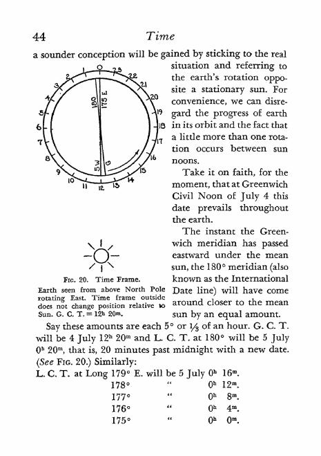
Standard or Zone Time is based on the L. C. T. of me-ridians at 15 intervals from Greenwich. For convenienceof railways and everyday affairs, a standard time zone ex-
tends 7.5 each side of these meridians in which the time
of the meridian is used. This system has been extendedover the oceans and is used by the navies of the United
States, Great Britain, France and Italy. The Greenwichzone is called Zero Zone. Each other zone is numbered from1 to 12 according to the hourly difference from Greenwich.East zones are called minus zones since in each of themthe zone number must be subtracted from the standard
time to obtain the G. C. T. Conversely, west zones are called
plus. The twelfth zone is divided medially by the 180th
meridian and the terms "minus** and "plus" are used in
the halves of this zone which lie in east longitude and west
longitude, respectively. (See Table 6.) These zone boun-daries are modified in the vicinity of land for special condi-
tions and circumstances. Instead of adjusting the ship'stime to apparent time at noon each day, the clock is adjustedto the standard time of the successive zones as they are
entered, the change invariably being exactly one hour.
When it is desired to obtain zone time from G. C. T., the
sign of the zone in question must be reversed and the result
applied to the G. C. T. Zone time has simplified the workof the navigator in many ways. His watch is usually kepton it.
Certain relations between Z. T. and L. C. T. may confuse
one at first.A study of Figures 1 8 and 1 9 should clear up this
problem.

40 Time
FIG. 18. Relations between zone time and local civil time.
The figure represents one instant only.
Mean sun is over 90th meridian W. Longitude.
Zone -f 6 time is 12 noon.
All other meridians in Zone + 6 have zone time 12.
Zone + 5 is one hour more.
Zone + 7 is one hour less.
L.C.T. of 90th meridian is 12 noon.
L.C.T. of meridians to east increases 4 minutes for each. (Fast of Z.T.)
L.C.T, of meridians to west decreases 4 minutes for each. (Slow of Z.T.)
FIG. 19. Zone time of mean sun noons in zone.
The figure represents 17 different instants. It shows at what zone time the
mean sun will be over each meridian.
Time
TABLE 6
ZONE TIMEZero Zone: Long. 7^ W.-71/5 E.
41
It is possible through daily radio signals to keep a second-
setting watch correct for G. C. T. However, many ships
still have no radio and use only the standard chronometer
which gains or loses at a certain rate. Most of the textbook
problems in navigation start the data with the observer's
watch time and proceed as follows:
W (Watch)+C W (Chronometer minus Watch; add 12 h. to
C. if necessary)C F (Chronometer Face)C C (Chronometer Correction)
G C T (Greenwich Civil Time)

42 Time
A newer form of recording the data for G. C. T. is as
follows:
Sights had best be taken with a stop-watch unless an
assistant is available to note time when observer calls for
it. Taking a sight with a stop-watch in the left hand is simple
and the stem may be punched at the instant desired. The
stop-watch can then be taken to the chronometer and
stopped when the latter reads some even minute. Subtract-
ing the stop-watch total gives the chronometer reading at
time of sight. This can be abbreviated as follows:
C. 5. (Chronometer at stop)R. W. (Ran stop-watch)
C. O. (Chronometer at observation)C. C. (Chronometer correction)
G, C. T. (Greenwich Civil Time)
Greenwich Date
Because chronometers do not have 24-hour dials, there
is always a problem, in applying a chronometer correction,
whether to add 12 hours for a P. M. hour at Greenwich.
Also the G. date may be that of the ship, one earlier, or one
later. Button gives the following quick and easy mental
method of G. C. T. and date determination:

Time 43
1-. Apply the zone description to the ship's approximatezone time, obtaining approximate G. C. T.
2. If it is necessary to add 24 hours to ship's time in order
to subtract a minus zone description, the G. date is one less
than ship's.
3. If after applying the zone description the total is over
24 hours, the excess is the G. C. T. and the G. date is one
more than ship's.
4. Otherwise the G. date is same as ship's.
One can diagram the problem by making a circle for
equinoctial and a dot in the center for north pole. West is
clockwise. Then draw projected local meridian to bottomand G. meridian according to longitude. Draw dotted lines
for their opposite (or lower branch) meridians. Draw symbolfor sun on circumference according to L. C. T. or Z. T. and
connect it to center.
G. C. T. will at once appear less or more than 12. If the
latter, add 12 to chronometer.
G. date is the same as local unless sun lies in the sector
between lower branches.
G. date is one more than local if sun is between lower
branches and west of G. lower branch.
G. date is one less than local if sun is between lower
branches and east of G. lower branch.
Change of Date
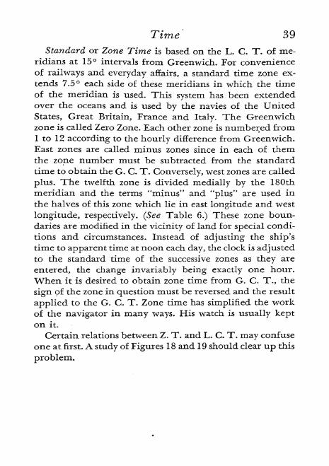
Greenwich Civil Noon is a unique instant. It is then, and
only then, that the same date prevails all over the earth.
We might discuss this matter of date by referring to the
sun's apparent motion around the earth, but it is felt that
44 Time
a sounder conception will be gained by sticking to the real
situation and referring to
the earth's rotation oppo-site a stationary sun. For
convenience, we can disre-
gard the progress of earth
[18 in its orbit and the fact that
a little more than one rota-
tion occurs between sun
noons.
Take it on faith, for the
moment, that at Greenwich
Civil Noon of July 4 this
date prevails throughoutthe earth.
The instant the Green-
wich meridian has passedeastward under the mean
sun, the 180 meridian (also
FIG. 20. Time Frame. known as the International
Earth seen from above North Pole Date line) will have come
around closer to the mean20^. sun by an equal amount.
Say these amounts are each 5 ori/%
of an hour. G. C. T.
will be 4 July 12h 20ffi and L. C. T. at 180 will be 5 July
Oh 20m , that is, 20 minutes past midnight with a new date.
(See FIG. 20.) Similarly:
L. C. T. at Long 179 E. will be 5 July Ob 16m.
178"
Oh 12*.
1 ^77 **f)k ft**i
176"
Oh 4m.
175" Oh Om .
doefSun. G. c. T. =
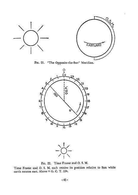
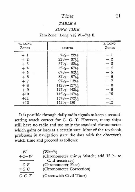
FIG. 21. "The Opposite-the-Sun" Meridian.
FIG. 22. Time Frame and O. S. M.
Time Frame and O. S. M. each retains its position relative to Sun while
earth rotates east. Above = G. C. T. 15h .
45-

o
I
Ss G
x &>G 5
V .3^ O qj'
<^ ^^ -Hr\r -_ *-''
-
l
O g
fr :
s ^
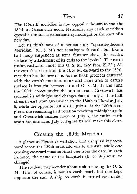
Time 47
The 175th E. meridian is now opposite the sun as was the
180th at Greenwich noon. Naturally, any earth meridian
opposite the sun is experiencing midnight or the start of a
new day.
Let us think now of a permanently "opposite-the-sun
Meridian" (O. S. M.) not rotating with earth, but like a
half hoop suspended at some distance above the earth's
surface by attachment of its ends to the "poles." The earth
rushes eastward under this O. S. M. (See FIGS. 21-22.) All
the earth's surface from this O. S. M. eastward to the 180th
meridian has the new date. As the 180th proceeds eastward
with the earth's rotation, more and more area of earth's
surface is brought between it and O. S. M. By the time
the 180th comes under the sun at noon, Greenwich has
reached its midnight and changes date to July 5. The half
of earth east from Greenwich to the 180th is likewise July
5, while the opposite half is still July 4. As the 180th com-
pletes the remaining half rotation reaching midnight again
and Greenwich reaches noon of July 5, the entire earth
again has one date, July 5. Figure 23 will make this clear.
Crossing the 180th Meridian
A glance at Figure 23 will show that a ship sailing west-
ward across the 180th must add one to the date, while one
crossing eastward must subtract one from the date. In each
instance, the name of the longitude (E. or W.) must be
changed.The student may wonder about a ship passing the O. S.
M. This, of course, is not an earth mark, but one kept
opposite the sun. A ship on earth is carried east under
48 Time
O. S. M. by the earth itself at the speed of its rotation, and
passes midnight in consequence. No ship could travel fast
enough (except near the poles) to pass under O. S. M. west-
wardly as that would require a speed greater than the speedof earth's rotation.
For practical convenience, separating continents, keep-
ing certain groups of islands under one time, etc., the In-
ternational Date Line is not just the same as the 180th
meridian. A glance at a globe will show the several angles
and curves that have been agreed upon.
Chronometers
Before the invention of a timekeeper which would re-
main close to correct in varying temperatures, navigators
were never certain of their longitude. About 30 miles was
as close as they could come by old methods of computa-tion, chief of which was through the measurement of
"lunar distances/' This meant getting the angle between
the edge of the moon and some other body by sextant, and
noting the time, from which, by elaborate corrections and
computations, the moon's right ascension could be found.
As this changes about 30" of arc in every minute of time, it
was necessary to observe within 30" of the correct dis-
tance to be correct within 1 minute. Consulting the alma-
nac showed at just what G. C. T. the moon had this
R. A. Comparing this G. C. T. with the ship's clock at
observation showed the error of the latter. Having thus
obtained a fairly correct G. C. T., observations could later
be made of the sun to get hour angle and hence Local
Apparent Time. G. C. T. with the equation of time gave

Time 49
G. A. T. Then L. A. T. compared with G. A. T. gave
Longitude.
John Harrison (1693-1776) was an English watchmaker.
When he was twenty years old, the British Governmentoffered a prize of 20,000 pounds for a method which woulddetermine longitude within 30 miles. Fifteen years later,
Harrison invented a compensating grid-iron pendulumwhich would maintain its length at all temperatures, and
applied unsuccessfully for the prize. By 1761, Harrison had
produced a better instrument. In 1764, this was taken to
Jamaica and back on a voyage of over five months and
showed an error of only lm 54.05 s
. It depended on the un-
equal expansion of two metals with change of temperature.The British Government awarded the prize to Harrison
who, however, did not receive it until nine years had passed.
Two years later, in 1776, he died at the age of 83.
The usual ship's chronometer of today is a finely madeinstrument kept in a box and swinging on gimbals to keepit level, which is wound regularly but not set after it is
once started correctly. The rate of change is noted and
correct time is calculated by applying this rate. It is cus-
tomary for a ship to carry three so that a serious error in
one will be manifest by its disagreement with the other
two. Chronometers are made with 12-hour dials which
sometimes necessitates adding 12 hours to the face to get
G. C. T.
Recently there have appeared what are called "second-
setting" watches. One model designed by CommanderWeems and in wrist-watch size, makes second hand setting
possible, without stopping the movement, by a device
which rotates the dial under the second hand. Another

50 Time
model, which has the advantage of a 24-hour dial, has a lever
which can stop the movement until the operator pushesthe lever back. On a small boat where radio time signals can
be had daily, this watch is probably an adequate substitute
for a chronometer.

3. The Nautical Almanac
THEAMERICAN NAUTICAL ALMANAC is issued
annually by the United States Naval Observatory and
may be obtained for the current or coming year for 65
cents in money order, from the United States Government
Printing Office, Washington, D. C.
The N. A., as it is called, is one of the four absolute
essentials of equipment for doing celestial navigation. Theother three are the sextant, the chronometer, and one of
the many types of tables necessary for computation.The student should spend sufficient time in looking
through the N. A. and reading the explanations printed in
its last pages to become thoroughly familiar with it.
As has been previously stated, navigational computationhas been shortened and simplified by the recent inclusion
of Greenwich Hour Angle for all bodies used. This and
the declination are the principal items for which we use
the N. A. The bodies, for which data are given are the sun,
moon, Venus, Mars, Jupiter, Saturn, and 54 convenient and
prominent stars. Special tables are provided for computinglatitude from Polaris and several 'other useful reference
tables are given.
Data are given at the following intervals:
Dec. G. H. A.
Sun . 2 h 2 h
Moon 1 h 1 h
Planets 1 day 1 dayStars 1 month 1 day
51-

52 The Nautical Almanac
Following the data for each of the bodies except the
sun, there will be found tables for computing any values
of declination and G. H. A. which lie between the values
given in the main tables. These save a great deal of arith-
metical interpolation. The sun's declination is easily in-
terpolated by inspection and its G. H. A. is corrected by a
table given on every third page. Star declinations hardly
vary from one month to the next.
While the use of sidereal time will not be advocated in
this book, many professional navigators use it and so the
tables, except those for the sun, give right ascension for
all the bodies. The first table in the N. A. gives sidereal
time of Oh civil time at Greenwich for every day in the
year, and another table (No. VI in 1943) gives the time
which must be added to the above with the excess of
G. C. T. over Oh in order to give Greenwich Sidereal Time.
The equation of time is given in the sun tables for
conversion of civil to apparent time. We shall find little
use for it.
A two-page table of mean places of 110 additional stars
is provided. It will be useful occasionally when a single
star is observed and proves to be neither Polaris nor a
planet nor one of the usual 54. In such case it may be
among these 110 and the older method of sidereal time will
have to be used to obtain t (the L. H. A.) since the R. A.
values are given without the G. H. A. data.
Tables are included for calculating times of sunrise,
sunset, moonrise, moonset, and twilight.
Commander Angas in An Introduction to Navigation
(VoL XIII. of Motor Boating's Ideal Series, p. 40) suggests
entering abbreviations for the month in the upper part

The Nautical A Imanac 5 3
of the star chart given in the N. A. as follows: At upper
right corner put Nov. Then passing to the left and skip-
ping one square, put Dec. Continue with Jan., etc., in every
other square to the left until Oct. occupies the second
square from upper left corner. "At nine p. m. local time
in the middle of each month, the observer's meridian will
about coincide with an imaginary vertical line on the
chart drawn through the center of the space occupied bythe month in question."
The writer has found it a great convenience to make upa correction table booklet from several old almanacs.
Bored with having to hunt through the almanac for the
proper correction tables following the given body's data,
he has cut out the necessary tables (which do not changefrom year to year), pasted them on loose-leaf sheets of reg-
ular typewriter size paper using one side only and bound
them in a 10 cent binder. Index markers make it easy to
turn at once to all the correction tables needed for any
body observed. Certain tables appear more than once,
but this makes each division complete in itself, Altitude
correction tables (to be discussed later) are included and,
since these appear in still another part of the almanac,
further saving of time is made possible, The arrangementis as follows:
SUN
Pages1. Height of Eye (Table C).
Altitude (Table A, sun portion).Additional altitude for semidiameter (Table B).
2. Greenwich Hour Angle.

54 The Nautical Almanac
MOON3. Height of Eye (Table C).
4-5. Altitude (Table D).6-7. Greenwich Hour Angle.
8. Declination.
PLANET
9. Height of Eye (Table C).Altitude (Table A, star portion).
1013. Greenwich Hour Angle.141 7. Declination.
STAR
18. Height of Eye (Table C).Altitude (Table A, star portion).
1921. Greenwich Hour Angle.
OTHER TABLES
22-23. Sidereal into Mean Solar (Table V).24-25. Mean Solar into Sidereal (Table VI).26-28. Proportional Parts (Table VII).
29. Arc to Time (Table VIII).30. Star transit corrections.
The American Air Almanac, published once In 1933 and then discontinueduntil 1941, is a simplified almanac issued in sections covering 4 months each.
It is arranged so as to usually give the desired data from a single opening.All values are to the nearest minute of arc. Interpolation is unnecessary.Button says it "can be used for surface navigation in open waters withoutfear of introducing any serious error. Near land it should only be usedwith caution because errors resulting from its use are not the only errors to
be expected in the observed position."

4. Altitudes
CELESTIAL HORIZON of an observer is the
JL great circle of the celestial sphere that is everywhere
90 from his zenith. At the extreme distance of the celes-
tial sphere it makes no difference whether the observer is
on the surface of the earth or is theoretically at the center
of the earth the great circles in these cases will practically
coincide. Altitudes of heavenly bodies are expressed in
angular distance from the celestial horizon with the ob-
server imagined to be at the earth's center. For the far
distant stars, there will be no difference if the altitude is
measured from the earth's surface, but for nearer bodies
sun and moon there must be a correction to our actual
observation.
True Altitude of a heavenly body, therefore, at any
place on the earth's surface, is the altitude of its center,
as it would be measured by an observer at the center o the
earth, above the plane passed through the center of the
earth perpendicular to the direction of the zenith.
Sextant Altitude, as measured at sea, must be converted
to the true altitude by application of corrections for certain
items as follows:
For sun and moon:
Index correction Refraction
Dip Parallax
Semidiameter55-

56 Altitudes
For planets and stars:
Index correction DipRefraction
Index Correction will be explained under the chapteron the sextant and is merely to correct a mechanical error
of that instrument that may be present.
Dip of the horizon, is the depression of the visible sea
horizon below the celestial horizon due to the elevation
of the eye of the observer above the level of the sea. Sex-
tant altitudes taken from the bridge of a steamer or even
the deck of a small yacht are enough larger than true alti-
tudes to require correction by N. A. Table C (Height of
Eye). The correction is, of course, subtracted (see Bow-
ditch, pp. 1534, for the influence of unusual conditions
of temperature and barometric pressure).
Refraction means the bending which rays of light un-
dergo when passing obliquely from one medium into
another of different density. If the latter be more dense,
the ray will be bent toward a perpendicular to the line
separating the two media. The earth's atmosphere in-
creases in density down to the earth's surface. Hence the
path of an obliquely incoming ray of light, by passingfrom a rarer medium to one of increasing density, be-
comes a curve concave toward the earth. The last direc-
tion of the ray is that of a tangent to the curved path at
the eye of the observer. The difference of this from the
original direction of the ray is the refraction. Refraction
therefore increases the apparent altitude of a heavenly
body. It does not change its direction laterally. At the
zenith, refraction is zero. At horizon it is greatest. The

Altitudes 57
correction must always be subtracted. (See FIG. 24.) TableA for sun, planet or star, and Table D for moon, include
correction for refraction.
POSITION
POSITION
HORIZON OF OEfcERVUl
FIG. 24. Refraction.
Parallax of a heavenly body in general is the angle be-
tween two straight lines drawn to the body from different
points. Geocentric parallax the only kind with which weare concerned is the angle subtended at a body by that
radius of the earth which passes through the observer's

FIG. 25. Parallax.
<j= Moon (Lower Limb) Observed.
JD = Parallax (N. A.)O = Observer.= Earth's Center.
C = Observed Altitude.
A = Altitude from Earth's Center = A' by Geometry.^' + jB = 180,andC + D -h B = 180, Therefore
^ + J5=:C + JDH-J^and/4'=C -fA Therefore
A=C +D.Altitude from Earth's Center = Observed Altitude 4- Parallax.
58-

Altitudes 59
position. Horizontal parallax is the maximum value of this
parallax for a particular body and is present when the bodyis on the observer's horizon. Parallax in altitude is the
parallax when the body is at any point above the observer's
horizon. It diminishes to zero at the zenith. Putting it
the other way around, parallax is the difference in altitude
of a body supposedly measured at the same instant from
a point on the earth's surface and, with parallel horizon,
from the earth's center. This is shown in Figure 25.
Parallax is always additive. Table A for sun and Table Dfor moon include corrections for parallax. The N. A. gives
horizontal parallax for the moon on each page with the
other moon data and we must note it for use with Table Dto correct sextant altitude. Parallax of planets may be
neglected in practical navigation.
Semidiameter of a heavenly body is half the angle sub-
tended by the diameter of the visible disc at the eye of the
observer. In cases of sun, moon and planets, whose dis-
tances from earth vary at different times, the semidiam-
eters will change. The moon is nearer an observer whenat zenith than when at horizon by the length of the earth's
radius and the ratio of this length to the total distance of
the moon is large enough to cause measurable enlargement.
(This shows that our ordinary impression that the moonlooks larger when low is an illusion. This effect is prob-
ably due to the nearness of earth landmarks, buildings and
so forth, which make the moon seem large by comparison.)
The increase in semidiameter due to increase in altitude
is called augmentation. Semidiameter is to be added* to
observed altitude in case the altitude of the lower limb of
a body has been measured and to be subtracted in the case

60 Altitudes
of the upper limb. Tables A and B include correctionsfor semidiameter for the sun and Table D for the moon.Semidiameter of planets may be neglected and of stars is
not measurable in navigation.For greater accuracy one should mentally make the sub-
traction for dip and the correction for index error first, anduse the result in entering the table containing correctionsfor refraction, finally using the algebraic sum of the dipand other corrections to correct the sextant altitude.
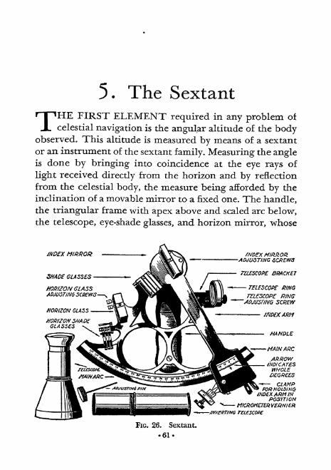
5. The Sextant
THEFIRST ELEMENT required in any problem of
celestial navigation is the angular altitude of the bodyobserved. This altitude is measured by means o a sextant
or an instrument of the sextant family. Measuring the angleis done by bringing into coincidence at the eye rays of
light received directly from the horizon and by reflection
from the celestial body, the measure being afforded by the
inclination of a movable mirror to a fixed one. The handle,the triangular frame with apex above and scaled arc below,the telescope, eye-shade glasses, and horizon mirror, whose
Mt> X MRRO&
SHADE GLASSES
HORIZON GLASSADJUSTING SCttWS
-ADJUSTING SCAEW8
TLSCOf> BRACKET
TELESCOPE RING
TELESCOPE PING~~ADJUSTING SCREW
HANDLE
4NDZXAKMINPOSITION
MICROMETERVEQNIER
FIG. 26. Sextant.
61-

o
HORIZON MIRROR
\
INDLX MIRROR'
Fxc. 27. Sextant Angles.
62-

The Sextant 63
right half alone is silvered, are all rigid parts of a unit.
The index mirror at top to catch the rays from the bodyis part of the movable arm which terminates below in the
vernier scale with its screws and magnifying glass. This is
moved along the arc, tipping the index mirror until the
two images are brought together. It is then clamped by a
screw on the right and the tangent screw on the left is
used for finer adjustment. The scale is then read to givethe angle of altitude.
In measuring the altitude of a celestial body, it is neces-
sary that the angle shall be measured to that point of the
horizon which lies vertically beneath the body. To deter-
mine this point the observer should swing the instrument
slightly to the left and right of the vertical about the line
of sight as an axis, taking care to keep the body in the
middle of the field of view. The body will appear to de-
scribe an arc of a circle, convex down. The lowest pointof this arc marks the true vertical.
When a ray of light is reflected from a plane surface, the
angle of reflection is equal to the angle of incidence. Fromthis it may be proved geometrically that, when a ray of
light undergoes two reflections in the same plane, the anglebetween its first and its last direction is equal to twice the
inclination of the reflecting surfaces. (See FIG. 27.)
The vernier is an attachment for facilitating the exact
reading of the arc scale of the sextant by which certain
fractional parts of the smallest division of the scale are
measured. A sextant vernier is a shorter scale usually con-
taining one more division than an equal length of the arc
scale. Both arc scale and vernier readings increase to the
left. To read any sextant it is necessary to observe the arc

64 The Sextant
ARCI
TO 150 iliil
The numbers are for each 10.The next highest marks are for 1 .
The next highest marks are for V2 = 30'.
The lowest marks are for 1/6 = 10',
VLRNILR
TO 10
Illil
FIG. 28. Arc and Vernier Scales.
When of Vernier is at arc, 10 of vernier is at 19 50' of arc. This is a
proportion of 50 to 119. The vernier has double spaces for clearer reading.Otherwise, the proportion would be 120 to 119.
scale division next to the right from the vernier zero andadd thereto the angle corresponding to that division of thevernier to the left which is most nearly in exact coinci-
dence with a division of the arc scale. Figure 28 shows thearc scale and vernier on a typical sextant,
Rule: The smallest measure to which a vernier reads
equals:
length of 1 division of scale 10' 10'
number of divisions of vernieras
60"= 10" or
l20= 5" etc *
Hence, after observation read thus. (See FIG. 29):

The Sextant 65
Scale: right of vernier zero to degrees and 10' units.
Find line on vernier to left of its zero closest to a scale
line.
Vernier number gives extra 1' units.
Vernier marks give extra 10" units.
Index Error exists when, with index and horizon mir-
rors parallel, the zero of the vernier does not coincide with
the zero of scale. Observe a star, or the sea horizon in day-
light, directly through telescope and move index until
reflected image coincides with direct. If now the vernier
zero is to left of the scale zero, all readings will be too great
by the amount of this divergence; if to right of scale zero,
readings will be similarly too small. (See Chap. 24 for
details.)
Index Correction (I. C.) is expressed as + or the
amount of arc to be applied to the observed amount.
Certain minute errors due to construction and not cor-
rectable by adjustment are usually noted in certificates
accompanying the instrument when purchased.Certain adjustments must occasionally be made. See
Button, pp. 219-20, for detailed information as to:
Index mirror Telescope Horizon mirror
Properly speaking*, instruments of the sextant familyshould be designated as follows:
Octant: 45 arc measures angles to 90
Sextant: 60 arc measures angles to 120
Quintant: 72 arc measures angles to 144
Quadrant: 90 arc measures angles to 180
o

66 The Sextant
The author's instrument, therefore, with an arc of 75
for angles to 150 would seem to qualify as a Super-
Quintant!
AND 10' 5PAC.E6
FIG. 29. Reading the Sextant.
Passing to left shows first coincidence at 75 50' of arc (Arrow).
Reading Arc =69 10'
Reading Vernier = 3' 20"
Reading Total = 69 13' 20"
The U. S. Navy now uses a sextant fitted with an end-
less tangent screw which carries a micrometer drum from
which the minutes and the tenths of a minute o arc are
read. The tangent screw is thrown out of gear by pressinga lever so the index arm may be freely moved. Releasingthe lever stops the arm at individual degrees and throws
the tangent screw into gear again for finer adjustment.
(See FIG. 26.)
An artificial horizon may be provided by a glass-roofed
dish of mercury or even a saucer of ink placed in an
uncovered box with sides low enough to let the body's raysin but high enough to keep moving air from rippling the
ink. The angle between the celestial body and its reflection
in the artificial horizon is measured by sextant. Half of

The Sextant 67
this angle equals the altitude of the body. (See Chap. 24
for details.)
A bubble sextant is an instrument containing a mech-
anism which supplies an artificial horizon. It is much more
expensive and less accurate than the standard type of sex-
tant but can be used when the natural horizon is invisible,
as in hazy weather, or in polar regions, on the desert, or
in an airplane high above the earth and clouds.
Historical
The evolution of the modern sextant probably beganwith the astrolabe, used by early Greek and Arab astron-
omers. It consisted of a graduated circle suspended in the
vertical plane from a ring at the top. At its center a sight-
ing bar was attached somewhat as a compass needle and,
by looking along this at a body and noting the scale on the
circle, altitude could be measured. Elaborate forms of the
astrolabe were in use in the sixteenth century.
Capt. John Davis, an English navigator, developed a
quadrant in 1594 which had two arcs and required sight-
ing in two different directions. A later form was used with
the observer's back to the sun. Many subsequent instru-
ments depended on a plumb line.
In 1729 Pierre Bouguer invented an instrument whichneeded only a sight of the horizon while a beam from the
sun was kept visible in line on a wooden peg.The cross-staff, something like a T square, was also in
use at about this time and necessitated sighting sun and
horizon separately. It too was used both facing and with
back to the sun.

68 - The Sextant
The double reflecting mirror instrument was suggested
in 1674 both by Robert Hooke, a professor of geometry in
London, and Sir Isaac Newton, independently, but no
models seem to have been made.
In 1730 Thomas Godfrey of Philadelphia and John
Hadley, an English astronomer, independently constructed
double reflecting instruments much like our sextants of
today. Hadley, who was Vice-President of the Royal Society
of London, probably suppressed Newton's notes and cer-
tainly ignored Godfrey's claim and obtained the credit for
the invention.
Capt. Campbell in 1757 enlarged the arc to make it a
true sextant. Up to 1775 the instruments were of all-wood
construction. Various improvements followed and the all-
metal sextant appeared in the early nineteenth century.Verniers then came into use although described by Pierre
Vernier long before, in 1631. Commander Hull of the
U. S. S. Constitution in 1812 used a sextant which hadshade glasses, telescope, vernier, ivory arc, brass fittings
and ebony frame while, at this same period, a similar in-
strument constructed of brass with a silver arc was in use
by Nathaniel Bowditch. Relatively minor improvementsfollowed but the sextant of today is not radically different
from its ancestor of 100 years ago. (See The Evolution ofthe Sextant by Commodore E. S. Clark, U. S. N. I. P. Nov.
1936, Navigational Antecedents by Commander H. D.
McGuire, U. S. N. I. P. May 1933 and The AmericanInventor of the Reflecting Quadrant, also by McGuire,U, S. N. I, P. Aug. 1940.)
6. The Compass
KNOWLEDGEOF THE LODESTONE and its influ-
ence on a piece of iron touched by it is of great
antiquity. Its use in a form to indicate directions at sea was
a subsequent development. The Chinese, Arabs, Greeks,
Etruscans, Finns and Italians have all been credited as
originators of the compass. Encyclopedia Britannica (14th
ed., Vol. 6, p. 176, "Compass") says . . . "the earliest defi-
nite mention as yet known of the use of the mariner's
compass in the middle ages occurs in a treatise entitled
De utensilibus, written by Alexander Neckam in the 12th
century. He speaks there of a needle carried on board ship
which, being placed on a pivot, and allowed to take its own
position of repose, shows mariners their course when the
polar star is hidden."
The Magnetic Compass of today as used on ships is the
Thomson (Lord Kelvin) instrument introduced in 1876
with a few improvements. Kelvin used several magneticneedles in parallel attached under a circular card on which
were printed the "points/* the whole supported on a pivot
for easy rotation. A subsequent improvement was filling
the compass bowl with an alcohol mixture and sealing it
under the glass cover, a corrugated chamber being pro-
vided for expansion of the liquid with increased tempera-
tures. Instead of the flat glass top, a modern developmentis the "spherical" (really hemispherical) glass cover. Com-
passes are swung on gimbals to keep them level when the
ship rolls or pitches, and mounted in a pedestal called a
69-

70 The Compass
binnacle. Through the bowl there is painted a thin black
line from front to back. This is known as the lubber's line
and the compass must be installed with this lineexactly
parallel to the ship's keel. The forward tip of the line,
visible over the compass card, is the mark by which the
helmsman notes the course, on the card, of the ship'shead.
Compass cards are marked in two principal ways:The old point system consists of 32 points around the
circle, starting from north as follows:
North Northeast by East
North by East East Northeast
North Northeast East by NorthNortheast by North East
Northeast etc.
Each point is 11 14 degrees from the next. A system of
quarter points is added, each being equal to about 2.8
degrees. The older (Merchant Marine) custom and thenewer (Navy) custom of naming these quarter points areboth somewhat difficult to memorize and of no real use to
the student.
The other method of marking is in 360 around thecircle clockwise. This system has many advantages asidefrom the fact that steamers can be steered to 1 while thesmallest unit of the point system is about 3. East is 90,South is 180, West is 270 and North is 360 or 0. Thissystem is all one needs at sea for celestial navigation.
Compass error results from two main causes, Variationarid Deviation, now to be discussed.
Variation. The earth may be thought of as a great

The Compass 71
magnet whose poles, however, do not exactly correspond to
the geographical poles. The north magnetic pole is at
about Lat. 70 N., Long. 97 W. and the south magnetic
pole at Lat. 73 S., Long. 155 E. (As unlike poles attract
and likes repel, the "north" end of the compass needle is
really "north-seeking" or south.) As the north magnetic
pole is above Hudson Bay and about 1200 miles below the
geographicalnorth pole, it will be evident that, in the
10
06 1 091
FIG. 30. Compass Card showing three methods of marking.

72 The Compass
Atlantic Ocean, the compass will point west of true north
and, in the Pacific, east of true north. The amount of this
divergence from true is called variation. As long ago as
1700, Halley constructed charts showing lines of equal
variation over the earth. Today we obtain the variation
from our charts for any locality. There is also a slow changewhich is noted on the chart as so much per year and, by
figuring from the date of the chart, the present amountcan be obtained.
Deviation is a further compass error due to magneticinfluences on the individual ship. The intricacies of the
subject need not be gone into here. Hard and soft iron,
horizontal and vertical iron, permanent, subpermanentand transient magnetism, are all terms used in the discus-
sion and explanation of deviation. It will suffice to under-
stand that, as a ship swings around, its metal and mag-netism will be brought into different positions relative to
the north point of the compass (which retains its general
position) and will exert varying pulls on it, sometimes to
one side and sometimes to the other. Deviation varies
with latitude.
Heeling error is similar. It occurs when the ship heels
or rolls to one side or the other. Iron which has been hori-
zontal approaches the vertical and vice versa. The compassis influenced by this alteration of magnetic force, chiefly
when on north and south courses.
Local magnetic disturbance is due to magnetic material
outside the ship in the neighborhood. In certain parts of
the world (Australia, Labrador, Madagascar, Iceland, the
Baltic, Lake Superior) this is a large source of error due to
mineral deposits in the ocean or lake bed. Minor causes

The Compass 73
are present at docks due to other vessels, metal, etc.
Correction of much of the error which develops with
the ship on different headings or due to heeling is done
by placing magnets and iron in certain positions near the
compass. This is called compass adjusting and should onlybe done by a thoroughly trained worker. Nothing is done
about local magnetic disturbance.
Conversion of true, magnetic, or compass courses, one
into another, is easy with the 360 card system. Between
true and magnetic, we must know the variation. Between
magnetic and compass, we must know the deviation. Bear
in mind that a course, however described in these three
ways, is the same direction on the earth. When a force pulls
the N. point of the compass in a clockwise direction, it is
called easterly and if counterclockwise, it is called westerly.
If deviation is 5 W. and variation 7 E., the error is the
algebraic sum or 2 E. If deviation is 6 W. and variation
2 W., the error is, of course, 8 W.When thinking for the first time of these disturbance!
of the compass card, it is a good scheme to think of the card
as having just been rotated in a certain way to a certain
extent and to imagine yourself pushing it back to its orig-
inal position. Say you are heading on a compass course of
20 and know that the deviation is 5 E. This means the
card has been forced 5 clockwise. Mentally push it back
5 counterclockwise. The heading will now be 25 or the
magnetic course. Then suppose you also know the varia-
tion is 6 E. This means the card has been forced 6 clock-
wise. Mentally push it back 6 counterclockwise. The
heading will now be 31 or the true course. In each case
we have added.

74 The Compass
Only one rule need be memorized and it is this: From
compass toward true add easterly errors.
This means that from compass to magnetic we add east-
erly deviation and from magnetic to true we add easterly
variation. Similarly we subtract westerly errors. From true
toward compass we do just the opposite: subtract easterlyand add westerly. Any one of these can be quickly thoughtout if we start from the one rule and make the necessaryreversals. Examples are shown in Table 7.
TABLE 7
COMPASS ERRORS
Methods of determining Deviation.
1. By bearings (azimuth) of the sun. This is the usual
method when at sea. Polaris and other stars may also be
used,
2. By comparison with a gyro compass.3. By reciprocal bearings.4. By bearings of a distant object.5. By ranges.
The first will be discussed later on in this book underAzimuth. The student is referred to Button, Chapter II,
for methods 2, 3, and 4: Method 5 which is probably the
simplest and most convenient for small craft not at sea,
may be briefly outlined as follows:

The Compass 75
a. Find some pair of objects in line, one nearer and one
farther, easily visible and shown on the chart, and deter-
mine the magnetic bearing of the line joining them, from
the water where you are located, by means of the "com-
pass rose" on the chart.
b. Send your boat across this line heading first 0, then
15 and every 15 around the circle, noting the bearingof the range at each separate heading.
c. Make a table showing the above and add a column
showing deviation on each heading, as in Table 8.
TABLE 8
FINDING DEVIATION
This table of deviations for each compass heading is
not sufficient for our needs. It does not tell us, what we are
more anxious to know, what compass course to steer in
order to make a given magnetic course. We want a table
arranged the other way around beginning with equal divi-
sions of magnetic and showing the proper compass course
for each.
The Napier Diagram is the means by which the above
is accomplished. Details will not be given here but the
student is referred to Bowditch or Dutton for a full
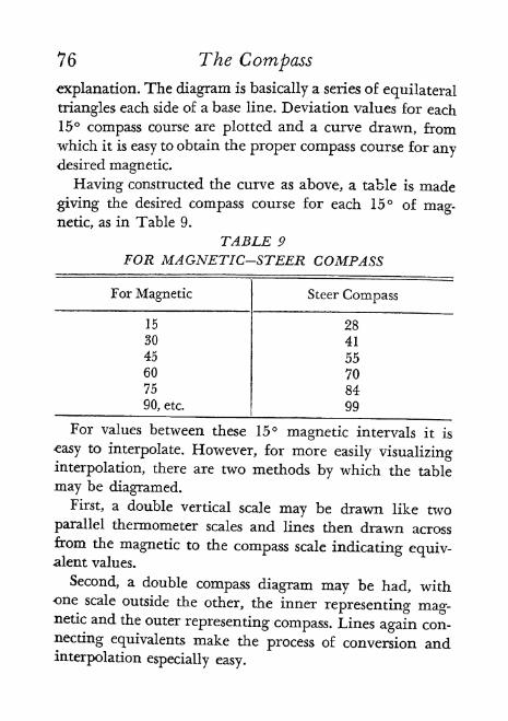
76 The Compass
explanation. The diagram is basically a series of equilateral
triangles each side of a base line. Deviation values for each
15 compass course are plotted and a curve drawn, fromwhich it is easy to obtain the proper compass course for anydesired magnetic.
Having constructed the curve as above, a table is made
giving the desired compass course for each 15 of mag-netic, as in Table 9.
TABLE 9
FOR MAGNETIC-STEER COMPASS
For values between these 15 magnetic intervals it is
easy tointerpolate. However, for more easily visualizing
interpolation, there are two methods by which the table
may be diagramed.
First, a double vertical scale may be drawn like two
parallel thermometer scales and lines then drawn acrossfrom the magnetic to the compass scale indicating equiv-alent values.
Second, a double compass diagram may be had, withone scale outside the other, the inner representing mag-netic and the outer representing compass. Lines again con-
necting equivalents make the process of conversion andinterpolation especially easy.

The Compass 77
The Gyro Compass obtains its directive force from the
force of the earth's rotation. A full description is given in
Bowditch. The essential feature is an electrically driven
wheel spinning at 6,000 r. p. m. whose axis seeks to remain
in the plane of its meridian. The attachments and mechan-
ical details result in a compass which has the following
advantages over the magnetic compass:
a. It is unaffected by the ship's magnetic field. (No devi-
ation.)
b. It seeks the true instead of the magnetic meridian.
(No variation.)
c. Its directive force is much greater.
d. It may be located in a safe and central portion of the
ship and repeater compasses directed electrically from it
may be located anywhere.
The disadvantages are:
a. It is a complex and delicate mechanism.
b. It requires a constant source of electrical power.
c. It requires intelligent and expert care.
d. It is expensive ($2,000 up).
An Azimuth Circle is a ring formed to fit flat over a
compass bowl and which can be turned to any desired
position. It is graduated from to 360 clockwise. Sight-
ing vanes permit the observer to take bearings of terres-
trial objects by turning the circle until the object is in line
with the vanes while a reflecting prism throws the compass
card into view at the same time. An adjustable dark glass
reflector brings celestial bodies into view and a concave
mirror and reflecting prism make it easy to take the bearing
of the sun.

78 The CompassThe Pelorus is a "dumb compass" or card without mag-
netic needles which can be turned to any desired position,and set. A lubber's line as in the compass marks the direc-
tion of the ship's head. Sighting vanes are provided. Pelo-ruses are placed so that views can be had in all directionswhich is seldom possible with the ship's compass. The cardis set to correspond with the heading of the ship by compassand then bearings are taken with it which are the same as
compass bearings.TABLE 10
COMPASS POINTS AND QUARTER POINTS SHOWING EQUIVALENT VALUEIN DEGREES
North to East
NorthNME
NbyENbyEJN by E
:NNENNENNEJ
JNHEbyNNEJiNTNEKNT
-NEbyE
NEbyEfc
ENE
EbyN
East to South
East
E^SEMS
EbySESE^EESEMEESE^E
ESESE by E%ESE by E^ESE by E34E
SEbyESEME
SE
SEbySSSEJ^ESSE^E
SSESbyES by ElS by E
SbyE
South to West
South
Sby WSby W}^S by WMASby WM^
sswSSWKWSSWJ^W
West to North
West
WbyN
WNW
NWby W
NW
NWbyNNNW^NNWU
NNWNby WN by WNby W
N^byW
Points
5
5%5%5%6
D. M. S.
0' 00*2 48' 45"5 37' 30"8 26' IS*
11 15' 00*14 3' 45"16 52' 30"19 41' 15*
22 30' 00"25 18' 45*28 7' 30*30 56' 15"
33 45' 00*36 33' 45"39 22' 30*42 11' 15*
45 00' 00*47 48' 45*50 37' 30*53 26' 15*
56 15' 00*59 3' 45*61 52' 30*64 41' 15*
67 30' 00*70 18' 45*73 7' 30*75 56' 15*
78 45' 00*81 33' 45*84 22' 30*87 11' 15*90 00' 00*
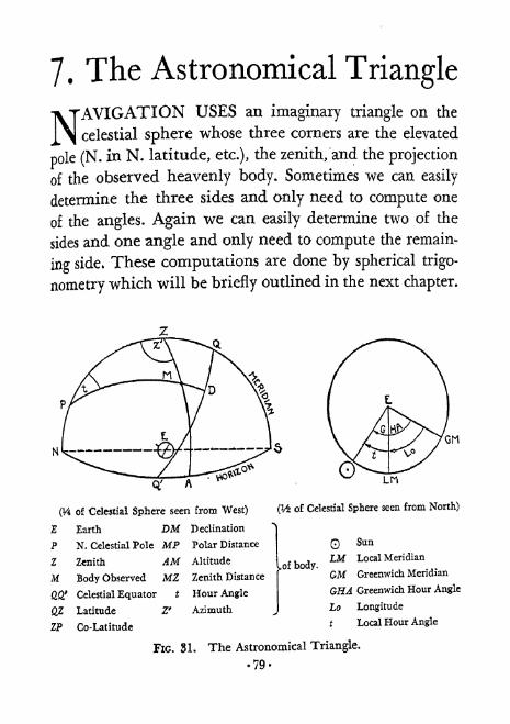
7* The Astronomical Triangle
NAVIGATIONUSES an imaginary triangle on the
celestial sphere whose three corners are the elevated
pole (N. in N. latitude, etc.), the zenith/and the projection
of the observed heavenly body. Sometimes we can easily
determine the three sides and only need to compute one
of the angles. Again we can easily determine two of the
sides and one angle and only need to compute the remain-
ing side. These computations are done by spherical trigo-
nometry which will be briefly outlined in the next chapter.
(V4 of Celestial Sphere seen from West)
Earth DM Declination
? N. Celestial Pole MP Polar Distance
Z Zenith AM Altitude
M Body Observed MZ Zenith Distance
' Celestial Equator * Hour Angle
QjL Latitude Z* Azimuth
ZP Co-Latitude
(V4 o Celestial Sphere seen from North)
.of body.
Q Sun
LM Local Meridian
CM Greenwich Meridian
GHA Greenwich Hour Angle
to Longitude
t Local Hour Angle
FIG. 3L The Astronomical Triangle.
79-

80 The Astronomical Triangle
For the present, we will consider what the principal rela-
tions are and leave solutions until Part II.
Remember that the celestial triangle is merely a magni-fication of a terrestrial triangle. Each part, side or angle,or relationship, on the celestial sphere corresponds to the
similar unit on the earth. Co-latitude (and hence, of course,
latitude), for instance, on the celestial sphere is the same in
degrees as that which we may be seeking on earth.
Figure 31 shows on the left a typical astronomical tri-
angle with the parts named. Remember that the angulardistance of a quarter circle, no matter of what size, is 90
so that if we know a portion of a quadrant we can find the
remaining portion by subtracting the first from 90. Thecircular figure on the right shows the celestial sphere as
seen from above with projections of the body and twoearth meridians.
Table 11 needs little explanation. The first columnshows what one starts with; the second shows what is
TABLE 11
FINDING PARTS OF THE ASTRONOMICAL TRIANGLE
*If L and d have opposite names (one N and one S) then p=90+d.

The Astronomical Triangle 81
thereby obtained; the third shows how it is used; and the
fourth gives the parts of the astronomical triangle thus
found.
Thus 3 sides and 2 angles of the astronomical triangleare sometimes obtainable without the use of formulas.
The remaining angle at the observed body is never neededin ordinary navigation.As the -fundamental relationships of celestial navigation
are here set forth, this table should be studied with greatcare and thoroughly understood.
The Celestial Co-ordinator is an ingenious device to give rapid approxi-mate solutions to problems of the astronomical triangle. It consists of a
rotating disc on a larger background. The type using the orthographic pro-jection has its under portion printed in black. It is a circle representingobserver's meridian with the upper half ruled with horizontal lines for
altitude circles every 5. These are crossed by elliptical arcs from the zenithfor azimuth circles every 5. Over this and fastened to it at the center is a
transparent circular disc ruled similarly but in red and in both halves. Its
border represents observer's meridian. A straight line across it is for the
equinoctial. Crossing this at right angles is the polar axis. Lines parallel to
the equinoctial are declination circles every 5. Elliptical arcs from the polesrepresent hour circles at 334 (15 minutes of time) intervals (in the typeproduced by the N. Y. Power Squadron). In using the co-ordinator the
upper part is set according to observer's latitude. Then various combina-tions of problems involving h, t, d, and Z may be solved. The greatest use-
fulness appears in star work. Given t and d, one gets the approximate hand Z which shows where to look for the star. Given h and Z of an unknownobserved star, one gets d and t. From t and known longitude, one getsG.H.A. With d and G.H.A. and the Nautical Almanac, the star can beidentified.

8. Trigonometry
NAUTICALASTRONOMY makes constant use of
trigonometry. The commonest example of this is the
need for computing altitude for comparison with a sextant
observation. This and various other needs will be ex-
plained in Part II. A knowledge of this branch of mathe-
matics is not essential to the navigator but some familiarity
with its fundamental concepts is highly desirable. There-
fore, both for the benefit of the novice and as a mind
refresher for those who at some distant past date have
studied trigonometry, the following pages are provided.
They contain enough to indicate the general features of
the subject and to suggest how various formulas, which
will appear later, may have been derived. Remember that
in plane trigonometry, only angles are measured in de-
grees. In spherical trigonometry not only angles but also
sides are so measured. The reader is referred for further
details to any modern text on the subject. An excellent
one is Palmer and Leigh: Plane and Spherical Trigonom-
etry, 4th edition (McGraw Hill Book Co., Inc., New York
and London, 1934).
Plane Trigonometry
This branch of trigonometry investigates the relations
that exist -between the parts of triangles which lie in a
plane,
82-

TABLE 12
DEFINITION OF THE TRIGONOMETRIC FUNCTIONSOF PLANE RIGHT TRIANGLES
(A and B = Acute Angles)
Q
b
Sin (sine) A
Cos (cosine) A
Tan (tangent) A
:
side opposite = A = cosB (s!n A = always < 1)
hypotenuse c
side adjacent
hypotenuse
: = sin B (cos A = always < 1)c
side opposite = _0
side adjacent b
( tan A under45= always < 1
45=always>l
side adjacent &jcot A under 45= always > 1 ?
Cot(cotangentU-
gide oosite-7" tan ^
| Cot A over 45-always < 1 J
hypotenuse _ __
side opposite a
RAVERSINES
1-cos ^l is called versed sin A (vers A)
% (1-cos 4) is called haversine A (hav
By formula (#22 in Palmer & Leigh) :
/
1-cos ASin H ^ - y
;1-T which, being squared, becomes:
SinaJ^^L = J^ (1-cos A).
Haversine of an angle = square of the sine of Y% the angle.
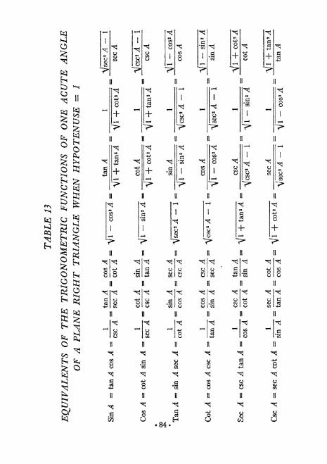
g
is + 8
8
+ +
w a + +55
x
a
1
>*
H
\\
n
*a
1
\
xj
4-
>-
n
n
^
o ta>-s ft^ 2
8 -I
xj
8
II
^_>
8
84

Trigonometry 85
The sum of the angles of a plane triangle= 180.
The complement of an angle = 90 minus the angle.The supplement of an angle =180 minus the angle.When one quantity so depends on another that for every
value of the first there are one or more values of the sec-
ond, the second is said to be a function of the first.
Connected with any angle there are six ratios that are of
fundamental importance, as upon them is founded the
whole subject of trigonometry. They are called the trigono-metric functions of the angle. To each and every anglethere corresponds but one value of each trigonometricfunction.
Tables 12, 13, 14, 15 will show the nomenclature usedand some of the fundamental relationships of the func-
tions of, first, acute angles and, second, angles of any size.
Spherical TrigonometryThis branch of trigonometry investigates the relations
that exist between the parts of a spherical triangle.A spherical triangle is the figure on the surface of a
sphere bounded by three arcs of great circles. The three
arcs are the sides of the triangle, and the angles formed
by the arcs at the points where they meet are the anglesof the triangle. The angle between two intersecting arcs
is measured by the angle between the tangents drawn to
the arcs at the point of intersection. The sum of the sides
of a spherical triangle is less than 360. The sum of the
angles of a spherical triangle is greater than 180 and less
than 540. In a spherical triangle there are six parts, three
sides and three angles, besides the radius of the sphere

TABLE 14
TRIGONOMETRIC FUNCTIONS OF ANY ANGLEWITH THE SIGN FOR EACH QUADRANT
(The sign of the hypotenuse or distance is always +)
ANGLE IN QUADRANT I II in IV. x
bin = -r
Cos
rt~\ *v
Ian = -y
Cot = -X
Sec-Jy
Csc = -X
NOTE: The angles here and in Figure 33 have been drawn
increasing clockwise (in contrast to Pigure 137 in Bowditch) so
as to conform to the 360 compass and its quadrants.
86*

Trigonometry 87
which is supposed known. In general, if three of these partsare given, the other parts can be found.
A right spherical triangle is one which has an angle
equal to 90. In such a triangle, two given parts in addi-
tion to the right angle are sufficient to solve the triangle.
Napier's Rules of Circular Parts. In a right spherical
triangle, omitting the right angle, consider the two sides
(a and b) adjacent to the right angle, the complements of
the two other angles (co-^4 and co-) and the complement
FIG. 32. For Napier's Rules.
of the remaining side (co-c). Arrange these in a circle as
in Figure 32. Any one of these five parts may be selected
and called a middle part; then the two parts next to it are
called adjacent parts and the other two parts, opposite
parts. Napier's rules are:
L The sine of a middle part equals the product of the
tangents of the adjacent parts.
2. The sine of a middle part equals the product of the
cosines of the opposite parts*
The ten formulas for solution of a right spherical trian-
gle can be derived from these two rules.

38 TrigonometryTABLE 15
EQUIVALENT TRIGONOMETRIC FUNCTIONS OFANGLES IN THE DIFFERENT QUADRANTS
(A = Acute)
(See Fig. 33)
Table 15 leads to the following rules which are useful in
certain "Sailings" problems which will be found in PartIII
1. The value of any function of any angle in the three
higher quadrants is always equal to the value of the samefunction of some angle in the first quadrant, as:
Given Angle in QuadrantnraIV
Corresponding Angle in Quadrant I
180 given anglegiven angle-180360 given angle
2. To find an angle, known to be in a higher quadrant,for a log in Table 33, Bowditch, take out the angle in
Quadrant I and treat as follows:

Trigonometry
(360 OR o8
)
89
(TO) -X
(To be used with Table 15)
FIG. 33. Angles in the Different Quadrants.
The A angles at center are constructed equal. Each A angle near circum-
ference equals A since its horizontal side is parallel, by construction, to the
X axis and, by geometry, a straight line (here a radius) connecting two-
parallel lines makes an angle on one side with the first line which is equalto the angle it makes on the other side with the second line.

90 TrigonometryFor Quadrant Use
II 180-angleinlIII 180+angte in I
IV 360- angle in T
Oblique Spherical Triangles are solved by formulas de-
rived from the following theorems:
1. Sine theorem. In any spherical triangle, the sines of
the angles are proportional to the sines of the opposite
.sides.
2. Cosine side theorem. In any spherical triangle, the
cosine of any side is equal to the product of the cosines
of the other two sides, increased by the product of the sines
of these sides times the cosine of their included angle.
3. Cosine angle theorem. The cosine of any angle of a
spherical triangle is equal to the product of the sines of
the two other angles multiplied by the cosine of their in-
cluded side, diminished by the product of the cosines of
the two other angles.
Examples:
(1) sin A _sin B _sin Csin a ~sin b ""sin c
(2) cos a = cos b cos c -f sin b sin c cos A
(3) cos A sin B sin C cos a cos B cos C
The following are useful haversine formulas for any
spherical triangle:
For an angle when the sides are given:
hav a hav (b ^ c]hav A =
= r =-^'
sin b sin c

Trigonometry 91
For a side when other sides and included angle are
given :
hav a = hav (b-^
c) 4- hav 6
where hav hav A sin b sin c

9* Logarithms
TRIGONOMETRICFORMULAS usually call for
multiplication of various long numbers. To multiplyone cosine by another and this perhaps by a haversine
would be a tedious process with old style arithmetic. By the
use of logarithms, the processes of multiplication, division,
raising to a power, and extracting a root of arithmetical
numbers are usually much simplified.
ItN= 6X, then x = the logarithm of N to the base 6.
The logarithm of a number to a given base is the expo-nent by which the base must be affected to produce that
number.
As 100 = 102 so logic 100 = 2, or the logarithm of 100 to
the base 10 is 2. This is abbreviated to log 100 = 2.
Logarithms were invented by Lord Napier of Scotland
(1550-1617) and described by him in 1614. He used the
base 2.7182818 called "e." This system is used in advanced
and theoretical work.
Prof. Briggs of London (1556-1631) modified the above
by using the base 10. This system is called the common or
Briggs system and is the one usually used in computingand is given in the 1938 Bowditch, Table 32 for logs of
numbers and Table 33 for logs of trigonometric functions
of angles.
The word "natural" is used to distinguish from the log-
92-

Logarithms 93
arithm. Table 31 gives natural, that is, actual values of,
sines, cosines, tangents and cotangents for all angles to 90.Table 33 is where one will find the log sines and log
cosines, as well as the logs of the other four trigonometric
functions, of angles to 180. Table 34 gives both natural
haversines and log haversines of angles to 360. (Althoughomitted to save space, -10 belongs after every log in Tables
33 and 34.)
Multiplication of two numbers is accomplished by add-
ing their logs and then finding the number of which this
sum is the log.
Division is accomplished by subtracting the log of the
divisor from the log of the dividend and then finding the
number of which this result is the log.
Raising to a power is done by multiplying the log of the
given number by the index of the power and then finding
the number of which this product is the log.
Extracting a root is done by dividing the log of the givennumber by the index of the root and then finding the num-
ber of which this quotient is the log.
The student should consult Bowditch, pp. 324-26, for
details.
While rules are given for obtaining logs of numbers and
numbers for logs, I believe the rules on the next two pageswill be found somewhat simpler.
Table 16 is to show examples of logs with various char-
acteristics (numbers to left of decimal point) for one man-
tissa (number to right of decimal point).

94 Logarithms
To Find Log of a NumberCharacteristic:
For number > 1 = 1 < the number of figures includingzeros to left of number's decimal point.For number < 1 = 9 - the number of zeros directly to
right of number's decimal point and -10 to right ofmantissa.
^
Manti&sa:*
Disregard decimal point of number when looking it upin Table 32 Bowditch.
F
For number of 1 figure: Add 2 zeros to right and treat as3 figures.
For number of 2 figures: Add 1 zero to right and treat as3 figures.
For number of 3 figures: Find number in left column andmantissa opposite it in column headed 0.
For number of 4 figures: Find first 3 in left column andmantissa opposite them in column headed by 4th figure.For number of 5 or more figures: Find mantissa for first 4.Then add to it the following: figure in column d x remain-ing figure or figures, first pointing off as many places as thereare remaining figures and disregarding fraction or, if itexceeds .5, raising total to next number.

Logarithms 95
To Find Number for a Log
May find exact mantissa in Table 32 Bowditch and take
out first 3 figures from left column and 4th from top.If mantissa lies between 2 given in table:
Take 4 figure number of next lower mantissa.
Note difference between next lower and given mantissa
(Istdiff.).
Note difference between next lower and next higher man-
tissa (col. d).
Note P. P. table under figure found for d.
Note 1st diff. figure in right column,
Note figure on same line in left column. This is 5th figure
of number.
If over 5 figures in number (as when characteristic is 5 and
number therefore has 6 figures to left of decimal point), get
4 figure number for next lower mantissa and then use
equation;
Istdiff.= 5th and succeeding figures. (Always < 1.)d
Disregard decimal point but retain any zeros that may come
between it and other figures and add 1 or more zeros on right
if characteristic calls for more figures in number.
If number is > 1 : Place point to right of 1 more figures
than number of characteristic.
If number is < 1 (log ending in 10 with characteristic 9
or less) : Subtract characteristic from 9 and add that manyzeros before figures already found and put point to left.

96
I?art II: I?:roceelTJLxres


10. Introduction to
Position Finding
SOLUTIONSFOR LATITUDE, as such, are not so
important in the modern practice of navigation as theyonce were. The same can be said of longitude. This is be-
cause, as we shall soon see, the newer navigation qbtains
from one observation a "line of position," on which the
ship is situated, and crosses this with another line from an-
other observation thus obtaining a "fix" on the chart, from
which the latitude and longitude can then be read off giv-
ing the exact position. Discussion and argument still go onbetween navy and merchant marine on the merits of the
newer methods. Inasmuch as the whole art and science of
position finding has evolved through first obtaining lati-
tude and longitude and because many officers of the mer-
chant marine still depend on these older methods and must
use them in their examinations for promotion, it seems well
to briefly explain them to the beginner.One of the first things to understand is the nautical
mile. It is defined in the U. S. A. as being 6,080.27 feet in
length, equal to 1^ part of a degree, or 1 minute of arc,
of a great circle of a sphere whose surface is equal in area
to the area of the surface of the earth. The earth is some-
what flattened at the poles which slightly alters the length
of 1 minute high on a meridian. This, however, is disre-
garded in navigation and a change of 1 minute of latitude
always is taken to mean a change of 1 nautical mile north
.QQ.

100 Position Finding
or south. Since the meridians converge toward the poles, the
difference of longitude produced by a change of position
of 1 mile to the east or west will increase with the latitude.
For instance, 1 mile on the equator will cause a change of
longitude of 1 minute while at latitude 60 it will cause a
change of 2 minutes.
Before doing any actual work, the amateur navigatormust understand the principles of the Mercator chart.
(Gerardus Mercator, Flemish cartographer, 1512-1594.) Thetransfer of a spherical surface, such as a globe map of the
world, onto a flat surface, presents many difficulties. The
portion of the globe between Lat. 60 N. and Lat. 60 S.
may, however, be transferred by placing a cylinder of
transparent paper around the globe, tangent at the equa-
tor, and projecting onto it the features of the globe as seen
from its center. Cutting this cylinder vertically at some
point and laying it out flat will show the meridians of
longitude not converging but as parallel vertical lines.
The parallels of latitude will be horizontal parallel lines
but farther apart the farther away they are from the equa-tor. As the distance between meridians becomes more andmore in excess of the true proportional distance, the in-
creasing distance between parallels makes up for it and
proportion in a given region is maintained. (This is not
literally accomplished as described but is done mathemati-
cally. See Button, Chap. I.) Of course, there is great dis-
tortion of areas in high latitudes. The great advantage of
a chart on this basis is that any course which cuts successive
meridians at the same angle becomes a straight line. If it
were cutting meridians at some angle other than 90 anddrawn on a globe, it would have to be a curve of a spiral

Position Finding 101
form. Such a curve is called a Rhumb Line. Scales of miles
as on ordinary maps are not possible here but, since a minute
of latitude equals a nautical mile, one uses the latitude scale
marked at the side of the chart at the level of the region
measured.
Position plotting sheets are blank charts made on the
Mercator system and important for the navigator in the
graphic solution of problems. One series issued by the Hy-
drographic Office is of 12 sheets covering latitudes from
to 60 and can be used for north or south of the equator.
The price is 20 cents a sheet, sold singly for a 5 area. Their
use saves the mutilation of charts, and they are large enough
(about 4x3 ft.) to permit the recording of sufficient data
for a good record. The parallels of latitude are, of course,
numbered, but the meridians of longitude are not. Theuser numbers the latter according to his location. A smaller
and more convenient size (26 x 19 inches) is issued in 16
sheets covering latitudes 0-49 and sells for 10 cents a sheet.
Tables of logarithms of trigonometric functions are nec-
essary for the solution of various equations which will
appear in the descriptions of the several procedures. Bow-
ditch (H. O. 9) contains all the essential tables. Amongthe many newer systems which have been devised for posi-
tion finding, H. O. 211 by Comdr. Ageton is the one pre-
ferred by the present writer. Reasons for this will be given
in the chapter on Short-Cut Systems. Meanwhile, equa-
tions will generally be presented in two forms. Both are
solvable by the Bowditch tables but the second in each case
is especially designed for solution by H. O, 211.
The several procedures will first be briefly outlined with
the idea that the student should get a rapid survey of the
102 Position Finding
general principles before getting" into the details of indi-
vidual problems. In Part III will be found examples worked
out for each of the more important procedures.
The expression "dead reckoning'' which will frequentlybe used comes from deduced (ded.) reckoning and is ab-
breviated to D. R, It is the method of finding a ship's posi-
tion by keeping track of courses steered and distances run
from the last well-known position. This is explained in
Chapter 21.
Throughout the following discussions of procedures,
preference will be given to the new methods in which
G. H. A. is taken from N. A,

11. Latitude
LATITUDE of a place is the arc of the meridian
X of the place subtended between the equator and the
place. It is labeled north or south in relation to the equa-tor. It may also be described as the angular distance on the
celestial sphere along the hour circle of the place betweenthe equinoctial and the projection of the place, or its
zenith. By geometry, it also equals the altitude of the ele-
vated pole.
Figure 34 shows the four cases which cover all latitude
calculations from observations of a body on the meridian.
It is important to study these and understand the equa-tions, which may be summarized as follows:
1 . L & d opposite names: L = z d
2- L 8c d same name ScL> d: L = z + d
3. L & d same name $cd> L: L = d z
4. L & d same name, lower transit: L = 180 -(d + z)
Regardless of what body is used, these principles apply.The next problem is to determine just when the body is
on the meridian. There are three ways:
L Measure with sextant the altitude of a body about to
make an upper transit, that is, crossing the meridian from
east to west, and continue to measure it at short intervals
noting the time of each observation, until the altitude
103-

L = d (90 h)= d z L = 180 [d + (90 7z)]
= h + (90-
d)= h + p
Each Big Circle = Projection of Celestial Sphere on Plane of the MeridianE = Earth M Projection of BodyP = Elevated Pole h
- - - -
Z = Zenith z
QQ' =Equinoctial d
NS = Horizon"
$pj= Latitude
FIG. 34. The Four Cases of Latitude from Meridian Altitude Observation.
104-
= Altitude= Zenith Distance= Declination= Polar Distance
Latitude 105
begins to decrease. Then take the greatest altitude as the
meridian altitude. This is not especially accurate, but is
often used for the sun.
2. Observe the true bearing of the body and measure
its altitude when it is directly south or north as the case
may be. With a good compass, steady ship and not too highaltitude, this gives fair results.
3. Calculate in advance the time of transit. This is the
most dependable method. It necessitates knowing the cor-
rect longitude if ship is stationary or moving true north
or south. If ship is making any progress east or west, the
rate of longitude change must be known in addition to
the longitude and time at the start of the calculation. Theusual method of making this calculation for apparentnoon is known as Todd's and was devised by him when a
midshipman at Annapolis (see Bowditch or Button).Tables based on his equations have been published as
H. O. 202 (Noon-Interval Tables).
Latitude by Noon SunThe G. C. T. of apparent noon may be found by the
following modification of Todd's method, using G. H. A.
without looking up Eq. T. No mention is made of watch
time or its difference from chronometer as this becomes very
confusing to the beginner and can easily be dispensed with
on smaller boats either by taking observations with chro-
nometer nearby or by setting a stop-watch exactly with
chronometer. The true sun is here assumed to be "mov-
ing" at the same speed as the mean (civil time) sun. Theerror of combining a mean time interval with a civil time
interval is immaterial (about 1 second per hour).

106 Latitude
Interval to Noon and G. G. T. of
Local Apparent Noon
1. G. C. T. at an instant in A. M. when longitude is
known.
2. G. H. A. of sun in arc from N. A. for this instant.
3. Combine G. H. A. with longitude obtaining t in arc,
always E.
4. Convert this arc into time. This is interval to apparentnoon at known longitude.
5. If ship is not changing longitude, add t in time (#4) to
G, C. T. (#1), obtaining G. C. T. of Local Apparent Noon.6. If ship is changing longitude, subtract t in time (#4)
from 12, obtaining!,. A.T.of beginning of interval.
7. Bowditch, Table 3: Enter with course in degrees (topor bottom of page) and speed in knots (col. labelled Dist.),
obtaining miles made E. or W in 1 h. (col. labelled Dep.).8. Bowditch, Table 3: Enter with latitude of ship (figure
for course in degrees, top or bottom of page) and miles madeE. or W, in 1 h. (col, labelled Lat.), obtaining change of
longitude . or W* in minutes of arc per hour (col. labelled
Dist.).
9. H, 0. 202 (Noon-Interval Tables): Enter with L. A. T.
o beginning of interval (#6) and change of longitude E. or
W. in minutes of arc per hour (#8), obtaining interval to
apparent noon with ship maintaining course and speed.10. Add this interval to G. C. T. (#1), obtaining G. C. T.
of L. A. N.

Latitude 107
Another and simpler method but which requires charting
is that of Commander Weems, Put in my own words it is as
follows:
Weems' Method for Interval to NoonandZ.T.orG.C.T.ofL.A.N.
1. At some time in morning determine sun's t east.
2. Convert this arc to time and fraction of hour to
decimal. (This is time sun needs to reach meridian of # 1
position.)
3. On chart from position of #1 run line for course as far
as speed for time of #2 would take ship.
4. Find DLo in minutes for length of this line. If not
due E. or W., drop perpendiculars from each end to middle
latitude and measure on that.
5. Since sun moves W, 15' per minute of time, divide
DLo of #4 by 15' to get time in minutes that sun would
require to cover this DLo.
6. If course is easterly, this time is saved, so subtract it
from time of #2 for interval to noon (sun on ship's me-
ridian).
7. If course is westerly, this time is lost., so add it to time
of #2 for interval to noon.
8. Apply this interval time to Z. T. or G, C T, of #1 to
get Z. T. or G. C. T. for noon sight at L. A. M
108 Latitude
The Meridian Sight
Whatever method of finding the proper time for the
meridian observation is used, the following steps must
then be carried out:
1. Take sextant altitude of body.
2. Note G. C. T.
3. Make usual altitude corrections.
4. Subtract from 90 to get z.
5. Find decimation in N. A. for G. C. T. of observation.
6. Combine d and z according to which of the four cases
was present and obtain latitude.
Reduction to the Meridian
A small cloud may spoil the actual meridian sight. Ob-
servations are therefore often taken any time within 28
minutes of noon, before or after, because such can be
''reduced" to the meridian by Tables 29 and 30 in Bow-
ditch. This procedure is based on the following equation:
Meridian altitude = corrected altitude at observation +
(change of altitude in 1 minute of time from meridian X
square of time interval from meridian passage) or H = h
+ a t2
.
Entering Table 29 with D.R. latitude and declination,
obtain a.
Entering Table 30 with this a and the time of observa-
tion from meridian passage (given for i/2 minute), obtain
at2.
This a t2
is to be added to a corrected altitude observed
near upper transit (or subtracted from a corrected altitude

Latitude 109
observed near lower transit) to obtain the corrected alti-
tude at meridian passage.
Having thus found the meridian altitude, it is treated
as explained under Meridian Sight to obtain latitude. Thislatitude is that of the vessel at the instant of observation.
The latitude at noon will depend on the run betweennoon and sight.
Latitude by Star, Planet and Moon Transits
Latitude may also be found by measuring the altitude of
some body, other than the sun, at meridian transit. This
procedure i$ not generally recommended. The time for
observation at twilight is quite limited and, while waitingfor a given transit, the horizon or body may fade. So,
only the one co-ordinate, latitude, is obtainable. Hence,the usual practice is to measure two or more stars whose
bearings differ by about 90, from which, as will be ex-
plained later, the exact position of the ship can be found.
The general principle of finding G. C. T. of transit is
this: Longitude must be known. When body is crossinglocal meridian, its G. H. A. = the longitude if west, or
360 minus the longitude if east. Hence find from N. A.
at what G. C. T. the body will have G. H. A. equal to the
longitude, or to 360 the longitude. This will be G. C. T.
of transit. Details of a new uniform procedure will be
found in Part III, Chapter 30, Problems, Transit.
Latitude by Polaris
The altitude of the elevated pole of the celestial sphere
110 Latitude
equals the latitude. So in the northern hemisphere, it is
convenient to measure the altitude of the north star or
Polaris which is close to the celestial pole and, by means of
certain tables in the N. A., "reduce" this altitude to that
of the actual celestial pole. Polaris has an apparent motion
counterclockwise in a circle with radius of about 1 around
the actual pole. The steps in the process to thus find latitude
are as follows (references are to 1943 N. A.):
1. Take sextant altitude of Polaris.
2. Note G. C, T. and longitude.
3. Make usual altitude corrections.
4. N. A. table for G. H. A. of Polaris (W) (p. 280) at
Oh G. C. T. of date.
5. N. A. Table "Correction to be added to tabulated
G. H. A. of stars" (pp. 214-16) using G. C. T. and obtain-
ing correction.
6. Add results of #4 and #5, subtracting 360 if over
360, obtaining G. H. A. at G. C. T. of observation.
7. Apply longitude to this G. H. A. obtaining L. H, A.
of Polaris (W).
8. N. A Table III (p. 284) entering with L. H. A. and
obtaining correction for L. H. A, to be applied to true
altitude.
9. Add this to or subtract it from true altitude obtain-
ing approximate latitude.
Latitude by Phi Prime, Phi Second
This old method for determining latitude fron! (1) a
single altitude of a body not on the meridian, (2) G. C. T.

Latitude III
of the observation, and (3) known longitude, is now seldom
used, but is given here as an example of one of the phases
of navigation which preceded the Saint-Hilaire method.
The method is best restricted to conditions where the
body is within 3 hours of meridian passage, of declination
at least 3, and not over 45 from the meridian in azimuth.
This last means that a line from body to zenith should not
make an angle of over 45 with meridian. (See FIG. 35.)
Projection of the Celestial Sphere on the Plane of the Horizon.
h = Altitude
Mm Perpendicular from Body to
Meridian = I
$>=mZ - Zenith distance of m= mQ = Declination of m
QZ = Latitude to be found
FIG. 35. Latitude by Phi Prime, Phi Second.
WQE = Equator2 = Zenith
P = Elevated Pole
M = Bodyd = Declination

112 Latitude
One of the two sets of equations given in Bowditch(1933)
for the solution is as follows:
sin / = cos d sin t
sin <" = sin d sec I
cos $ = sin h sec /
Give <j>"same name as d.
Mark</>'
North if body bears north and east or north
and west.
Mark<j>'
South if body bears south and east or south
and west.
Combine f and <" by adding, if different names or sub-
tracting, if same.
The result will be latitude, except in the case of bodies
nearer lower transit when 180 <" must be substituted
for <". (The rules for marking <' and for combining are
Bowditch's reversed, in order to make the process conform
to other procedures in general use.)
As the author has pointed out (U. S. N. L P. Sept. 1935),
these Bowditch equations can be converted for satisfactory
use with H. 0. 211 substituting R for / as follows:
esc R = esc t sec d
cscdesc d>" =Y
csch

Latitude 113
Summary1 . Take sextant altitude of body.2. Note G. C. T. and longitude.3. Make usual altitude corrections.
4. N. A. for declination and G. H. A.
5. Combine G. H. A. and longitude for t.
6. Solve by 211 method for latitude.
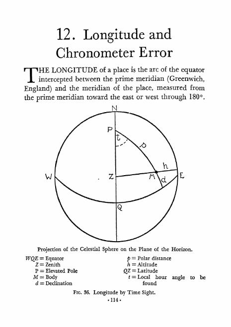
12 . Longitude and
Chronometer Error
THELONGITUDE o a place is the arc of the equator
intercepted between the prime meridian (Greenwich,
England) and the meridian of the place, measured from
the prime meridian toward the east or west through 180.
N
Projection of the Celestial Sphere on the Plane of the Horizon.
WQf,= Equator p = Polar distance
Z = Zenith h = Altitude
P = Elevated Pole QZ - Latitude
M = Body t = Local hour angle to bed = Declination found
FIG. 36. Longitude by Time Sight.
114-

Longitude 115
The "Time Sight" method for longitude dates back to
1763 and is still much in use in the merchant service
though not in the navy. It calls for (1) a single altitude of a
body preferably near the prime vertical (bearing east or
west), (2) G. C. T. of the observation and (3) known lati-
tude. Practically, the body should be between 3 and 5 hours
of meridian passage, (See FIG. 36.)
The long-used equation for this problem is:
hav t = secL esc p cos s sin (s h)
where s = Vz (h + L + p)
Having thus found t, it is combined with the G. H. A.
from N. A. to give longitude.
Hulbert Hinkel, Jr. (U. S. N. I. P. April 1935) presented
the following substitute equation for use with H. O. 211:
sec s esc (s h)
Summary1. Take sextant altitude of body.
2. Note G. C. T. and latitude.
3. Make usual altitude corrections.
4. N. A- for declination and G. H. A.
5. Solve by 211 method for t.
6. Combine t with G. H. A. for longitude.
NOTE: A method for finding the time at which the sun will be on the prime
vertical will be found in Part III, Chap. 30, Problems.

116 Chronometer Error
Chronometer Error
Radio time signals now furnish the best means of deter-
mining chronometer error at sea.
In some circumstances, however, the radio receiver may
fail, or there may be no radio. In such case, if correct
longitude is known, the process is as follows:
L Take sextant altitude of body as near prime vertical
as possible.
2. Note chronometer (approx. G. C. T.) and longitude.
3. Make usual altitude corrections.
4. N. A. for declination.
5. Solve by 211 method for L
6. Combine t with longitude for G. H. A.
7. N. A. to find the G. C. T. of this G. H. A.
8. Difference of this G. C. T. from chronometer equals
part or all of error.
9. If body was sun, moon, or planet, go back to #4 and
use the revised G. C. T. found in #7 to pick out more
exact declination. Use it in repeating #5 and repeat re-
maining steps through #7. Difference of this second
revised G. C. T. from chronometer will show practically
all error.
NOTE: The method for #7 of finding from N, A. what the G. C. T. is for
a certain G, H. A. is the same as the method of finding G. C. T. of transit.
(See Part HI, Chap. 30, Problems, Transit.)

13* Azimuth and
Compass Error
A ZIMUTH of a celestial body is the angle at the zenith
,/\between the meridian of observer and the vertical
great circle passing through zenith and the body. It is
usually measured from the north in north latitudes, east
or west through 180, and similarly from the south in
south latitudes and designated Z. It is also measured from
the north point clockwise through 360 and is then iden-
tical with true bearing and labeled Zn . (See FIG. 37.)
Azimuth of a body is needed for two main purposes: (1)
for drawing a line of position, as will be explained in the
next chapter, and (2) to determine the error of a magnetic
compass.Azimuth is found by the following means:
L Gyro compass (with azimuth circle).
2. Table.
3. Formula (with and without sextant observation).
4. Diagram (with and without sextant observation).
5. Celestial Co-ordinator.
6. N. A. (after obtaining latitude by Polaris).
The first is possible because of the fact that gyros showtrue directions with no deviation or variation.
The second is much used. H. O. 71 ("Red" Azimuth
Tables for declinations - 23 and to Lat. 70, usuallyfor the sun) and H. 0. 120 ("Blue" Azimuth Tables for
117-

118 Azimuth
declinations 24 70 and to Lat. 70, for stars) are the
standard books. Entering with L, d, and t (the first two in
even degrees and the last in I0-minute time intervals)
gives Z. A rather long and tedious calculation is necessary
in most instances because the quantities usually lie between
N
Projection of the Celestial Sphere on the Plane of the Horizon.
WQE Equator M = BodyZ'= Zenith Z= Azimuth direct from Ele-
p = Elevated Pole vated Pole
Zn= Azimuth by 360 system
FIG. 37. Azimuth.
these entering values and interpolation is necessary.
"Cugle's Two-Minute Azimuths" recently published in
two volumes are more expensive, but also save some time.
They are arranged on the same basis as the H. O. volumes
except for having 2-minute time intervals. They cover lati-
Azimuth 119
tudes to 65 and declinations to 23. H. O. 66, Arctic
Azimuth Tables, is a small volume, also on the same basis,
for latitudes 70 - 88 and declinations to 23. It is lim-
ited to the hours 4 to 7 A. M. and 5 to 8 P. M. at 10-min-
ute intervals. H. O. 200 includes a short table which is
entered with hcy d and t and requires some interpolation.
It covers declinations to 89 30'.
The new series of volumes, H. O. 214 (see Chap. 16),
provides probably the most satisfactory means of similarly
finding azimuth. L is in whole degrees, d in whole and usu-
ally half degrees and t in whole degrees which correspondsto 4-minute time intervals. The volumes already published
carry latitudes to 79 and decimations to 74 30'. (A prob-lem showing method of interpolation will be found in
Chapter 30.)
There are many formulas for azimuth, but they all fall
into the following three classes:
Time Azimuth (Z obtained from t, p3 and L). The equa-tions and method are lengthy and will not be given here
but may be found in Bowditch.
Altitude Azimuth (Z obtained from h, p, and L). Collins'
equation (U. S. N. I. P. July 1934) is recommended:
hav Z = sec h sec L sin (s h) sin (s L)
where s = Yz (h + L + p)
Hinkel (U. S. N. I. P. June 1936) gives the following for
use with H. O.211:
2 sec h sec L
In either case it is measured from N. in N. lat. and from

120 Azimuth
S. in S. lat. The quantity s p may have a negative value
but this does not matter since the secant of a negative angleless than 90 is positive. (See Table 14.)
Time and Altitude Azimuth (Z obtained from t9 h, and
d). The Bowditch equation is:
sin Z = sin t sec h cos d
There is a defect in this method in that nothing indi-
cates whether the azimuth is measured from north or south.
However, as the approximate azimuth is always known, the
solution will almost always be evident. When in doubt, with
sun almost E. or W. and L and d same name, find altitude
when sun is E. or W. as follows: sin h = esc L sin d. If ob-
served altitude was less, sun was on side toward elevated
pole, etc.
Using H. 0.211:
esc t sec desc Z =
sec h
An azimuth diagram is often accurate enough for prac-tical purposes and saves much of the time ordinarily spentin calculating formulas or interpolating tables. A copy of
Rust's azimuth diagram comes with one of the short-cut
systems, Weems' "Line of Position Book." Entering with
t, h, and d one arrives at Z. Another diagram by Capt. Weiris mentioned by Button. Weir's uses t, d, and L to obtain Z.
A Celestial Co-ordinator (see Chap. 7) set for L, t and d
will give approximate values for Z and 7z.
The azimuth of Polaris may be found from the Nautical
Almanac as follows:
1. Find approximate latitude by procedure given in
Chapter 1 1 under Latitude by Polaris.

Azimuth 121
2. Enter Table IV (p. 285 in 1943 N. A.) with L. H. A.
and approximate latitude and take out azimuth.
SummaryTime Azimuth
1. G. C. T. and L. and Lo. (or t).
2. N. A. for G. H. A. and d(p = 90 d).
3. G. H. A. and Lo. for t (unless given).
4. Table (H. O. 66, 71, 120, 214 or Cugle's) or formula or
diagram (Weir).
Altitude Azimuth
1. Sextant altitude.
2. G. C. T. of observation, and L.
3. Make usual altitude corrections*
4. N.A.ford( = 90d).5. Formula,
Time and Altitude Azimuth
1. Sextant altitude.
2- G. C. T. of observation, 2md Lo.
3. Make usual altitude corrections.
4. N. A. for G. H c A. and d.
5. G. H. A. and Lo. for t.
6. Formula, or Table (H. O. 200), or diagram (Rust).
Azimuth of Polaris
1. Latitude by Polaris.
2. N. A. Table IV.

122 Compass Error
Compass Error
The compass azimuth, taken with an azimuth circle, o
a body, usually the sun and preferably at low altitude, is
compared with the true azimuth of the body, which is de-
termined by one of the methods described. The difference
is the error: variation plus deviation. The difference be-
tween this total error and the variation, obtained from the
chart, is the deviation on the particular heading.

14. Sumner Lines of Position
CAPT.THOMAS H. SUMNER, an American ship-
master, on December 18, 1837, near the end of his
ship's voyage from Charleston, S. C., to Greenock, Scotland,
was in need of data as to his position. About 10 A. M. an
altitude of the sun was obtained and chronometer time
noted. As the D. R. latitude was unreliable, two additional
latitudes 10' and 20' farther north were assumed and the
three possible longitudes were worked out. When the three
positions were plotted on the chart, they were found to be
in a straight line. "It then at once appeared that the ob-
served altitude must have happened at all the three points
. . . and at the ship at the same instant." The conclusion
was that, although the absolute position of the ship was
uncertain, she was necessarily somewhere on that line. Capt.
Sumner published his discovery in 1843 and it is considered,
with the previous invention of the chronometer and the
subsequent development of the Saint-Hilaire method, as
one of the three greatest contributions to the science of
navigation.
Circles of Equal Altitude
If we look up at the top of a vertical flagpole from a
certain distance away from, its base, we will be gazing
upward at a certain angle. We may walk all around the
pole keeping at the same distance, but this angle will not
change.
123-

124 Sumner Lines of Position
It is obvious that a heavenly body directly over the nonh
pole would show the same altitude from every point on a
given parallel of north latitude.
It is somewhat less obvious but none the less true that, if
a certain heavenly body is in the zenith at a point anywhere
on the earth at a given time, and if circles in the same
hemisphere are imagined around this point as a center,
then the altitude of such body from every point of any one
circle at the given time will be the same. Measuring the
radius of such a circle in degrees on the earth's surface,
the largest possible circle, dividing the earth into hemi-
spheres, would have a radius of 90, From any point on
this circle of 90 radius, the body would be in the horizon
and have an altitude of 0. From the center with radius 0,
the body would be in the zenith and have an altitude of 90.
On a circle with radius of 10 the body's altitude would be
80, etc. The radius is, therefore, the complement of the
altitude and so equals the zenith distance. Expressing it in
minutes of arc, the zenith distance equals the number of
nautical miles the observer is away from the center of the
circle, where the body is in the zenith. (See FIG. 38.)
In an astronomical sight, the following is learned about
the point on the earth in whose zenith the body is:
1. Longitude-from G. C. T. and G. H. A.
2. Latitude from d.
3. Distance from observer from h.
There is nothing to show at what point on the circle of
equal altitude the observation was made. But an observa-
tion of another body preferably in a direction at right angles

Sumner Lines of Position
if
125
* = Extremely distant fixed star
Circle = Earth in plane of vertical circle of body observed
Z = Zenith of observer
OB = Line from observer toward bodyh = Altitude
z = Zenith distance' = Place on earth where body is in zenith (geographical position)
ZO is prolonged to center of earth at O'
O'B' is parallel to OB considering distance of body
Therefore, by geometry: Angle OO'B' = angle ZOB, or angular distance on
earth from observer to body's geographical position= zenith distance of
body at place of observer (for nearer bodies, parallax correction makes them
equal anyway).
FIG. 38. Zenith distance and the Radius of the Circle of Equal Altitude.

1 26 Sumner Lines of Position
to the first (or the same body several hours later) can be
made in order to get a new circle.
This will intersect the first circle at two places, one of
them being the ship's position. But as the ship's position is
always approximately known within about 30 miles, and as
these two intersections may be thousands of miles apart,
there is no question as to which is the correct one.
The Line of Position
It is never necessary to determine the whole of a circle of
equal altitude. A very small portion of it is sufficient, and
such an arc may be considered as a straight line for the
length needed to cover the probable limits of the position
of the observer. Such a line is known as a Sumner line or
line of position. It gives a knowledge of all the probable
positions, while a sight worked with a single assumed lati-
tude or longitude gives only one probable position. It always
lies at right angles to the direction of the body from the
observer, as a tangent to a circle through a point is perpen-dicular to the radius at that point.
In the two earlier line of position methods, sights were
worked for latitude when the body was nearer north or
south and for longitude when the body was nearer east or
west. The three methods of determining a line of positionare as follows:
1. Chord method: for one sight assume two values of
latitude and determine longitudes or assume two values of
longitude and determine latitudes. Two points are thus
fixed on the chart and the line joining them is the line of
position.
Sumner Lines of Position 127
2. Tangent method: for one sight assume one latitude orone longitude and determine the other co-ordinate. Onepoint on the line is thus obtained. The azimuth of the bodymust now be found either by formula, table, or diagram,and a line drawn from the one point at this angle in thedirection of the body. Then perpendicular to this line andthrough the point is drawn the line of position. When usingthe time-sight formula for longitude, it is convenient to
also use the altitude azimuth formula. When using the PhiPrime, Phi Second formula for latitude, one should usethe time and altitude formula for azimuth.
3. Saint-Hilaire method: assume both latitude and longi-tude using either the D. R. position or one nearby andcalculate what the altitude and azimuth of a body wouldbe, there, at the time an actual altitude was taken on the
ship. The difference between the actual and the calculated
altitude shows how far to move along the azimuth line fromthe assumed position before drawing a perpendicular. Thisis the line of position. (This method will be discussed inmore detail in the next chapter.)

15. Saint-Hilaire Method
THEFRENCHMAN Adolphe Laurent Anatole Marcq
de Blond de Saint-Hilaire was born at Crcy-sur-Serre
(Aisne) July 29, 1832 and entered the French Navy in -1847.
He was made a Commander of the Legion of Honor in
1881 and reached the rank of Contre-Amiral in 1884, fol-
lowing distinguished service in the Tunis expedition. Hedied in Paris, December 30, 1889. Little information is
available about him. His method of the calculated altitude
was published as "Calcul du point observe. Methode des
hauteurs estim^es/' in "Revue Maritime et Coloniale" Vol.
XLVI, pp. 341-376, August 1875. He split the astronomical
triangle by dropping a perpendicular from the body ontothe meridian and solved the resulting right spherical trian-
gles by logarithms, using the D. R. position.
Lord Kelvin before the Royal Society, February 6, 1871,
had announced a method of comparing calculated withactual altitude for locating the line of position. He used anassumed position and computed tables for solving the tri-
angle. These were published as "Tables for FacilitatingSumner's Method at Sea" in 1876.
It would be interesting to know if Saint-Hilaire knew of
Kelvin's announcement, and when Saint-Hilaire first devel-
oped his method.
Everything so far in this Primer has been leading up to
the Saint-Hilaire method. It is a most important develop-ment in the science of position finding and is the basis of
practically all modern navigational systems.128*

Saint-Hilaire Method 129
Details of Procedure
1. Take an altitude and note G. C. T.
2. Make usual altitude corrections.
3. Note D. R. latitude and D. R. longitude.4. N. A. for G. H. A. and d.
5. Combine G. H. A. and D. R. longitude for t (for D. R.
position).
6. With t, d, and L using one of several formulas to be
given and perhaps tables or a diagram, calculate altitude
(h c)and azimuth (Z). These are the values the body would
have had if the observation had been made at exactly the
D. R. position.
7. The difference between your observed altitude cor-
rected as in #2 and the calculated altitude of #6, in min-
utes of arc, represents the difference in miles between youractual distance from the place where the body is in the
zenith, called its geographical position, and the distance of
the D. R. position from the body's geographical position.
(We could compare the observed zenith distance with a
calculated zenith distance but the altitude way is more
convenient.) This difference is called the altitude difference
or intercept and is given the abbreviation a. If the observed
altitude is greater than the calculated, it means your actual
position was nearer the body's geographical position than
was the D. R. position. (You were more "under" the body.)
But if your observed altitude is less than the calculated,
then you were really farther from the body's geographical
position than was the D. R. position. (You were less "under"
the body.) The a is, therefore, labeled "toward" or "away."

130 Saint-Hilaire Method
8. Through the D. R. position on the chart draw a line
at 'the calculated azimuth angle in the direction of the body's
geographical position.
9. Lay off on this line from the D. R. position a distance
in miles equal to the intercept, either toward or away from
the body's geographical position, as the case may be.
10. Through the end of this intercept draw a line per-
pendicular to the azimuth line. This is the line of position.
(See FIG. 39.)
One of the best formulas for calculating the altitude
called for in #6 is known as the cosine-haversine and is
described by Button as "the most widely used formula of
trigonometry applied to nautical astronomy. It is univer-
sally applicable to all combinations of the values of t, d, andL." Here it is:
hav z = hav (L ~ d) + hav
where hav & = have t cos L cos d
from which hc- 90 - z
(L and d: add opposite names, subtract likes)
Convenient to use with this is the time and altitude azimuthformula:
sin Z = sin t cos d sec hc
Other formulas or tables or a diagram may also be used.
The cosine-haversine formula and a formula for azimuthshould be memorized once and for all by every student
navigator. Knowing these one could be independent of all
short-cut systems and could function even when only tables
of a foreign publication were available.

Saint-Hilaire Method 131
GEOGRAPHICAL POSITION
OF BODY
UNKNOWN POSITION OF
(h.
LQUM. KLTITUDL / ^N^
D,R. posmon
PARALLEL
FIG. 39. The Saint-Hilaire Method.

132 Saint-Hilaire Method
The Fix
We have seen that one line of position does not fix the
exact location of the ship. Another line must be obtained
which will intersect the first giving what is called a fix, andso show the real position. The second line preferably should
be at about 90 to the first although a smaller angle downto 45 may be effective. The ideal fix is probably from three
stars at about 120 intervals around the observer, giving 3
lines which should intersect at a point or at least with
formation of a small triangle. When the same or another
body is used later in the day to get the second line, the first
must be moved forward parallel to itself according to the
course and distance made good. These latter factors are
estimates from compass and log readings or engine revolu-
tions and open to error through current, wind, etc. Hencea line which is over five hours old in a moving ship is nottrusted. A fix obtained after moving forward a previousline is known as a running fix.
The best method for a series of two or more star sights is
to use the D. R. position at the time of the last of the series
in working each sight. Then plot the line for the last sightin the usual way but advance the lines of the previous sights
according to time difference, speed and course of ship to
get fix at time of last sight.
When chart work is impossible, a method for computingthe position of the intersection of position lines (Bowditch,pp. 190-3) may be followed. This requires knowledge of the
position of one point on each line and so the lines had best
be obtained by the tangent method. (See Chap. 14.)
Saint-Hilaire Method 1 33
The various practicable combinations of observations for
a fix are as follows:
Daylight
Separated
Sun and Sun
Simultaneous or close
Sun and Moon
Sun and Venus
Venus and Moon
Twilight
Simultaneous or close
Star and Star
Star and Planet
Star and Moon
Planet and Planet
Planet and Moon
The Computed Point
This is the point where a line from the D. R. position
dropped perpendicular to the line of position intersects
the latter. It is the mean of the possible positionsof the
ship on the line. It, therefore, is the best point to use as the
ship's probable position in the absence of an intersecting
line and without contrary evidence from weather or
current.
16. Short-Cut Systems
A RESUME OF NAVIGATION METHODS in tab-
ular form by Soule and Collins, copyrighted by the
U. S. Naval Institute, was published by the U. S. Hydro-
graphic Office as "Supplement to the Pilot Chart of the
North Atlantic Ocean" in 1934. It gives a ready compari-son of the salient features of twenty-nine different methods
for determining the elements of the astronomical trianglein order to plot the line of position. There are seventeen
systems working from an assumed position and three from
the D. R. position, making twenty for the Saint-Hilaire
method. The remaining nine are longitude methods for
chord or tangent lines. Since this publication, I know of
five more methods which have appeared: Aquino's'
'Tan-
gent Secant Tables," "Hughes* Tables for Sea and Air
Navigation/' Ageton's "Manual of Celestial Navigation"
(for D. R. or A. P.) and H. O. 214 (all of which use the
Saint-Hilaire method) and Aquino's method for findinglatitude and longitude directly.
Assumed vs. D. R. Position
The advantages of using an assumed position are that
fractions of degrees of latitude or hour angle may beavoided and arithmetic simplified. Dutton (7th ed., p. 204)states that any position correct to within about 40' may be
used. "No matter what position is assumed within the 40'
limit, the line of position will plot in the same place on the

Short-Cut Systems 135
chart, the altitude difference, a, changing with each changeof assumed position." The chief disadvantage is that chart
work is complicated by using a different assumed position
for each of several sights taken in a short interval. This
means drawing each azimuth line through a different point.
Another bad feature is that long altitude intercepts mayresult.
The advantages of working from the D. R. position are:
it is run forward on the chart from the last fix; only the one
position is plotted for any group of sights; errors are more
apparent; much smaller altitude intercepts result which
makes for accuracy; and (theoretically) the azimuth should
be more accurate. The disadvantages are that a little more
arithmetic and time are required.
In view of the foregoing and after using both, the writer
has chosen the D. R. position system. Of the various meth-
ods and tables available, he recommends the use of "HL O.
211" by Comdr. A. A. Ageton, U. S. N. Its full title is "Dead
Reckoning Altitude and Azimuth Table."
H. 0.211
Advantages of H. O. 211 are as follows: It gives sufficient
accuracy without interpolation; except for H. O. 214, it is
the shortest D. R. method; it follows a uniform procedure
for sun, moon, star or planet; it consists of only one table of
36 pages running in two columns of almost all whole num-
bers; the table is indexed and very simple and easy for rapid
use; azimuth is determined without question as to origin;
and there are only two special rules. (See FIG. 34.)
The only disadvantage is that when the hour angle lies

136
Rule 1:
Short-Cut Systems
1 ft is > 90K is always < 90 I^ J Take iC from bottom ofTake from top of table! when
jtable
Z is always > 900 f . _ _ . ,
Take Z from hot- LcxcePt
JA 1S same name as &> latltude
torn of table Jwhen 1 Take Z from top of table
Rule 2:
.,Of course, if ^ =^ takes same name as declination (N. or S.)
FIG. 40. Rules for H.O. 211.
(Projection of celestial sphere on plane of horizon. R is dropped from
body M, perpendicular to meridian.)

Short-Cut Systems 137
within about 3 of 90 the solution requires such close
interpolation that Ageton recommends discarding those
sights.
The table consists of double columns of log cosecants and
log secants each X 105 which eliminates decimal points in
all but a few pages. Without interpolating between the
values, which are given for each half-minute of arc, accuracy
(excluding, of course, sextant errors) is withini/%
mile.
The formulas used, derived from Napier's second rule,
are as follows:
esc R = esc t sec d
esc desc K =
sec Resc h c
= sec R sec (K -'
L)esc R
esc Z =sec hc
Give K same name as d.
K '' L: subtract likes, add opposites.
NOTE: See Part III, Chap. 29, for convenient forms to use
with H. O. 211. See Ageton, A. A.: "The Secant-Cosecant
Method for Determining the Altitude and Azimuth of a
Heavenly Body." U. S. Naval Institute Proceedings. Oct.
1931, Vol. 57, No. 344, pp. 1375-1385.
H. O. 214
This recent development in navigational tables is en-
titled "Tables of Computed Altitude and Azimuth/' The
complete set will consist of nine volumes. Eight have already

138 Short-Cut Systems
been published covering latitudes to 79 (10 to a volume).Either the D. R. or an assumed position may be used. The
procedure in either case is the shortest of its kind possible
at present. The azimuth from the table may be interpolatedfor the D. R. position if extreme accuracy is desired. Tables
for star identification are included at the end of the data for
each degree of latitude. The fact that the whole set is of
nine volumes need not discourage the average cruising
yachtsman, since each volume covers 600 miles in latitude.
A few of the volumes will probably be sufficient in most
cases.
In Chapter 30 will be found a fix from two stars workedout by H. O. 214 with both the D. R. position and the as-
sumed position methods.
It will be seen that the method which uses the D. R.
position for each sight exceeds in length the method usinga different assumed position for each by two short altitude
corrections (L andt)and a combination of the three cor-
rections, for each sight.
However, the method using a different assumed positionfor each sight requires the calculation of the assumed longi-
tude, sometimes by a subtraction, and the plotting of each
azimuth line from a different point. The intercepts are
usually much longer from assumed positions and the azi-
muths not quite so accurate.
The following summaries will show each step.
H. O. 214: Method Using D. R. Position
1. Take an altitude by sextant and note G. C T.
2. Make usual altitude corrections for h .

Short-Cut Systems 139
3. Note D. R. Latitude and D. R. Longitude.4. Find d and G. H. A. in N. A. and t from G. H. A. &
D. R. LQ.
5. Enter tables with nearest whole degree of latitude and
local hour angle and nearest whole or half degree of declina-
tion.
6. Copy the 4 values found which will be h, Z, A d and At. These last two represent the change in altitude due to a
change of 1' of arc of declination and of local hour angle.
7. Calculate by inspection the differences between fig-
ures used to enter tables and actual values of d, t (D. R.)
and (>.#.)8. Use table on back cover pages to multiply d and t
differences (found in #7) by A d and A t respectively.
Give each result a + or a sign according as the tables show
the altitude to be increasing or decreasing in passing from
the chosen tabulated value toward the value to be used.
These are altitude corrections for d and t.
9. Use another table in back of book entering with Ldifference (found in #7) and azimuth (found in #6) and
take out altitude correction for L. With Z > 90: if D. R.
latitude exceeds chosen tabulated value, give L correction
a sign; otherwise mark it +. With Z < 90: if D. R. lati-
tude exceeds chosen tabulated value, give this L correction
a + sign; otherwise mark it .
10. Combine these three altitude corrections algebra-
ically.
1 1 . Combine the resulting total with altitude from table
(found in #6) to get h .
12. Combine hc and h for intercept.
13. Plot from D. R. position.

140 Short-Cut Systems
H. 0. 214: Method Using Assumed Position
1. Take an altitude by sextant and note G. C. T.
2. Make usual altitude corrections for h .
3. Note D. R. Latitude and D. R. Longitude.
4. FinddandG.H.A.inN.A.
5. Assume the whole degree Latitude nearest D. R.
6. Assume Longitude nearest D. R. which when com-
bined with G, H. A. will give a whole degree for t.
7. Enter tables with assumed latitude and local hour
angle and nearest whole or half degree of declination.
8. Copy the values found for h, Z and A d. This last rep-resents the change in altitude due to a change of 1' of arc of
declination,
9. Calculate by inspection the difference between decli-
nation used to enter tables and the actual declination.
10. Use table in back cover pages to multiply d difference
(found in #9) by A d. Give result a + or - sign accordingas the tables show the altitude to be
increasing or decreasingin passing from the chosen tabulated value toward the
value to be used This is the altitude correction for d.
11. Combine this correction with altitude from table
(found in #8) to get h c .
12. Combine hc and h for intercept13. Plot from the assumed position.

17. Special Fixes
A>ARTFROM THE USUAL TYPE of fix described
in Chapter 15, there are several methods for certain
circumstances, some of which will now be described.
The Zenith Fix with Sumner Arcs
When the altitude of a body is over 89 its zenith distance
is, of course, a matter of less than 60'. It will be recalled
that the zenith distance of a body in minutes of arc repre-
sents the distance in nautical miles from observer's positionto the geographical position of the body, namely, that pointon earth which has the body in its zenith. (See FIG. 38.)
Ordinary lines of position under these circumstances are
not accurate because a straight line here will only coincide
with a very small part of the circle of equal altitude. It is
better to draw the actual circle or an arc of it. This can be
done as follows:
Take a sextant altitude 3 or 4 minutes before transit,
note G. C. T. and make usual corrections. The G. H. A. of
the body at this G. C. T., obtained from N. A., represents
the west longitude of its geographical position. The decli-
nation represents the latitude of its geographical position.
This point can, therefore, be plotted on the chart or plottingsheet. With the point as a center and with dividers set bythe latitude scale for the number of miles equal to minutes
of zenith distance, an arc can be swept in the general direc-
tion of the ship. Following a similar observation from the
141-
142'
Special Fixes
same position about 3 or 4 minutes after transit, another
arc from a new center can be similarly swept which will
intersect the first and give a fix. In case the ship has mean-
while moved, the first arc can be advanced by shifting its
center according to course and distance covered to give a
fix at second observation. Or the second arc can be pushedback similarly to give a fix at first observation. For accuracy,
a third arc from an observation at transit may be used, but
is not essential.
The azimuth in this situation is rapidly changing from
east of the meridian to west of it. If body is to transit be-
tween zenith and elevated pole, azimuth (on the 180
system) will diminish to and then increase. If body is to
transit with zenith between it and elevated pole, azimuth
will increase to 180 and then diminish.
Theoretically, this method should apply to any body
passing near zenith but it is unlikely that a star would be
found and satisfactorily observed in this way at twilight.
With the usual method available of a fix from two stars
there would be no need for it.
Practically, it is of occasional use in daylight with the sun
at noon or Venus at transit. These bodies will only passnear zenith if the ship is in low latitudes and when decli-
nation and latitude are about equal. (See Lecky, 22nd ed.,
p. 500; Button, 6th ed., p. 212; Bugger, U. S. N. I. P. Jan.
1936.)
The Noon Fix with Equal Altitudes
This is described by Lecky (22nd ed., pp. 482-4). Noonlatitude is obtained by a meridian altitude in the usual way.If the ship is practically stationary and the sun's altitude
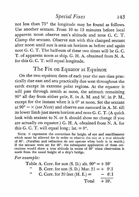
Special Fixes 143
not less than 75 the longitude may be found as follows.
Use another sextant. From 10 to 15 minutes before local
apparent noon observe sun's altitude and note G. C. T.
Clamp the sextant. Observe sun with this clamped sextant
after noon until sun is seen on horizon as before and againnote G. C. T. The half-sum of these two times will be G. C,
T. of apparent noon at ship. G. H. A. obtained from N. A.
for this G. C. T. will equal longitude.
The Fix on Equator at EquinoxOn the two equinox dates of each year the sun rises prac-
tically due east and sets practically due west throughout the
earth except in extreme polar regions. At the equator it
will pass through zenith at noon, the azimuth remaining90 all day from either pole, E. in A. M. and W. in P. M.,
except for the instant when it is at noon. Set the sextant
at 90 X (see Note) and observe sun eastward in A. M. till
its lower limb just meets horizon and note G. C. T. (A quicklook with sextant to N. or S. should show no change if youare actually on equator.) G. H. A. obtained from N. A. for
this G. C. T. will equal long.; lat. = 0.
NOTE: X represents the corrections for height of eye and semidiameterwhich must be allowed for in order to observe the sun at a true altitude
of 90. (Parallax and refraction do not operate when body is in zenith.)If the sextant were set for 90, the subsequent application of these cor-
rections would show a true altitude in excess of 90 when observation is
made from the usual height of a ship's bridge.
For example:
Table A. Corr. for sun (S. D.) alt. 90 = + 16'"
B. Corr. for sun (S. D.) Mar. 21 = + O'.l
"C. Corr. for 39 feet (H. E.)
= - 6'.1
Total + 10'.
144 Special Fixes
Reversing the sign and applying to 90
90 00'
89 507 = sextant setting.
At any other time of day on equator at equinox, if a
sextant altitude is taken, and corrected, then t = 90 h
and t combined with G. H. A. for time of observation =longitude; latitude = 0.
The Fix on Equator Not at EquinoxHinkel (U. S. N. I. P. June 1936) gives the following
equation for local hour angle, to be worked by H. O. 211,
when on equator, not at equinox, but with a definite value
for the sun's declination.
esc hsec t =-
sec d
Combining t with G. H. A. gives longitude; latitude = 0.
Aquino's Fix from Altitude and Azimuth
Capt. Radler de Aquino of the Brazilian Navy in his
article "A Fix from Altitude and Azimuth at Sea and in
the Air" (U. S. N. I. P. Dec. 1936) presents a method of
obtaining a fix from simultaneous sextant and compassobservations of a single body. The azimuth must be takenwith a gyro compass in perfect order or with a magneticcompass whose error is definitely known. The student is
referred to the original article for details, equations used
Special Fixes 145
and their derivation but it is sufficient to state here that
latitude and longitude are obtained directly from the rea-
sonably short calculation. A form for the procedure is
given in Chapter 29 and a sample problem in Chapter 30.
Any tables containing log tan, log sec and log esc for everyT of arc may be used. Aquino has prepared an especiallyconvenient table of these functions which is contained in
his "A Navega^ao Hodierna com Logaritrnos de 1633!"
This can be purchased from R. de Aquino, 133 Rua Raul
Pompeia, Copacabana, Rio de Janeiro, Brazil. The tables
occupy only 18 pages. The practical difficulty in this other-
wise ideal method is, of course, in obtaining a sufficientlyaccurate azimuth.
The Fix with Weems' Star Altitude Curves
Star Altitude Curves, published by the Weems system of
Navigation, Annapolis, Maryland, represent a new develop-ment in position finding and under favorable conditions
offer the means for obtaining a fix in the amazingly short
time of two minutes.
The following items are dispensed with: assumed posi-
tion, Nautical Almanac, right ascension, hour angle, azi-
muth and the plotting of position lines.
The student is referred to the publisher for details or can
find a good description in Button, 7th ed., pp. 352-5.
Very briefly, each page is a "grid" formed by the respec-tive equal altitude curves, or lines of position, of three stars
plotted on a Mercator chart at 10' intervals against latitude
(left and right edges) and local sidereal time (top and bot-
tom). One of the stairs is usually Polaris.

146 Special Fixes
At the top are shown the names of the stars used on that
page and the half or whole hour of local sidereal time whichis covered. Each page covers about 10 of latitude and the
collection covers latitudes from to 70 30' and local side-
real time from Oh to 24h.
No correction is needed when the altitudes are observed
with a bubble sextant. With a standard sextant, only the
correction for dip of the horizon is used.
For any place and sidereal time, a circle of equal altitude
of a star remains nearly the same from year to year. Anannual correction is indicated under the name of each star
at the top.
A second-setting watch on G. S. T. is used, or else G. C. T.is converted to G. S. T.
The procedure in simplest form, for northern hemisphere,is as follows:
1. Apply approximate longitude (in time) to G. S. T. to
obtain approximate L. S. T.
2. Turn to the corresponding page for this time and for
the approximate latitude.
3. Observe altitude of one of the "longitude stars" andnote G. S. T.
4. Observe altitude of Polaris. (Time of this is not nec-
essary, as altitude of Polaris changes so slowly.)5. Find the proper altitude line and fraction on the
Curves for the longitude star and do the same for Polaris.
Mark the intersection of these two lines.
6. Project this intersection horizontally to the scale to
find latitude.
7. Project this same point vertically to the scale to find
L. S. T.

Special Fixes 147
8. Take the difference between this and G. S. T. of ob-
servation to find longitude in time.
9. Convert above to arc to find longitude.This remarkable procedure is at present most suitable
for high-flying fast airplanes. The limitation to the three
stars given on each page without curves for sun, moon or
planets, make it a supplement to, rather than a substitute
for, the usual methods of marine celestial navigation.

18. Polar Position Finding
THEAMATEUR NAVIGATOR will rarely be con-
cerned with lines of position in arctic regions. How-
ever, two reasons have led me to include something of
these matters in this Primer: first, we will be completing
the story of position finding for the whole earth instead
of the usual limit of 65 latitude N. or S.; second, there is
practically nothing printed about polar position finding
in any of the texts or manuals in common use.
Let us consider for a moment certain special conditions
which exist at, say, the exact geographical north pole. After
understanding these, we can more easily understand the
conditions in the neighborhood of the pole which are simi-
lar but which become less so, the farther away from the
pole we go, until they gradually become those with which
we are already familiar in latitudes below 66.
At the North Pole
At the north pole, then, every direction radiating out
from an observer is south.
Circles drawn with observer as center will be leading
west clockwise or east counterclockwise.
The horizon of an observer at the north pole marks the
equinoctial, or celestial equator, above which all bodies
are in northern declination. A north declination as given
in N. A. will then be the true altitude, Sextant altitudes,
-148*

Polar Position Finding 149
of course, would differ by the amount of the usual cor-
rections.
The sun at Spring equinox, March 21, appears above the
horizon and skims around it in about 24 hours. It remains
visible and rises gradually to an altitude of about 23 27'
at summer solstice, June 21. It then gradually sinks to dis-
appear at Fall equinox, Sept. 23, and remains invisible for
the six months of arctic night.
The moon's declination is north about one half of each
month and at such times, of course, this body will be above
the horizon. It sometimes attains an altitude of over 21.The presence of the sun does not make it invisible and so
when the two are in evidence they can often be used for
lines of position which intersect and give a fix.
All stars of northern declination are theoretically visible
during the arctic night from Fall to Spring equinox. As
their declinations change so little from year to year, this
upper half of the "inner surface of the celestial sphere"
presents an unvarying picture except for the moon and
planets.The four navigational planets appear at times during
arctic night. Naturally their different orbits and varying
declinations will change the program from year to year.
In 1938, for instance, Venus was in northern declination
from March 1 6 to August 9, Mars from February 1 to Octo-
ber 29, Jupiter at no time, and Saturn from March 6 to
the end of the year but never as much as 5, which is too
low an altitude for navigational use. Conditions favoring
visibility of a planet in northern declination during the six
months of arctic daylight would be: more altitude, more
angular distance from the sun, and less bright sunlight.

150 Polar Position Finding
There is no azimuth at the pole, since true north is in
the zenith.
Polaris when visible will be found within 1 1'.6 of the
zenith.
To find direction of Greenwich: choose a heavenly body,find its G. H. A. in N. A. for a given instant, set a peloruswith this G. H. A. on the body at the time chosen, andon the pelorus will point toward Greenwich. The direction
of any other place will be its longitude west, read in de-
grees on pelorus, as 74 for New York City.
The north point of the magnetic compass will point south
toward the magnetic north pole or approximately alongthe meridian of longitude 97 W. (The latitude of the north
magnetic pole is about 70 N.)A gyro compass, started with N. point toward Green-
wich, for instance, theoretically should hold its direction
steady in relation to the universe and so appear to makeone clockwise revolution in one sidereal day, as the earth
turns under it counterclockwise. "Actually, however, this
result would not be mechanically possible due to friction
of the supports. This would produce a slight tilt of the gyroaxis, which in turn would result in a continuous precessionabout the vertical axis due to pendulousness of the compass."
(Sperry Gyroscope Co., Inc. communication.)
Owing to ice floes making the horizon rough, a bubblesextant is necessary. This supplies its own horizon.
Being on top of the spinning world, the rule that "dayand night are equal at equinox" is not quite true at or nearthe pole. One has to get away far enough to be able to havesome of the earth come between oneself and the sun to
make any night possible at all.

Polar Position Finding 151
In Polar Regions
The behavior of the magnetic compass in polar regionsdeserves some mention. At the north magnetic pole it be-
comes useless inasmuch as the directional force is to pullthe north end downward. A dipping needle supported on
a horizontal axis proves this. Getting away from the mag-netic pole the compass gains in directional force, but this
never becomes as strong as it is in our latitudes. Supposethe compass is carried around the geographical north poleon the parallel of latitude 80 N. Starting north of the
magnetic north pole, the north point of the compass will
point south and variation ~ 180. Continuing east on the
80th parallel, this variation will be west and will steadily
decrease till a point is reached about halfway around the
parallel when compass will be pointing true north and
variation = 0. Still continuing east, the compass will be-
gin to show east variation which will steadily increase till
our starting point has been reached when variation again= 180.
The nature of the Mercator chart makes it useless for
high latitudes and so a polar great circle chart is used. (See
Chap. 21.) A straight line drawn on this represents a por-tion of a great circle. This is usually sufficiently close for a
true line of position although the latter is always part of
a "small circle/' (A straight line on a Mercator chart simi-
larly is a rhumb line and not truly a part of a small circle.)
A method for allowing for curvature in long position lines
will be explained.The astronomical triangles in polar problems are pe-
culiar in that the side between elevated pole and zenith is

c-o
g
OK
i
1

Polar Position Finding 153
relatively much shorter. However, this does not prevent,
except in extreme cases, using H. O. 211 for solutions or
the cosine-haversine formula for calculated altitude. H. O.
66 "Arctic Azimuth Tables" may be used in certain lim-
ited conditions. (See Chap. 13.) Weems' "Line of Position
Book" Polar edition 1928, is a system using an assumed
position for which the tables have been extended to include
all latitudes.
Weems, in an article "Polar Celestial Navigation" (U. S.
N. I. P. Nov. 1933), suggested a method preferred for
position finding within 5 or 10 of the pole. Briefly it is
as follows:
Note D. R. position on polar chart, Greenwich meridian
up.Assume observer is at pole, in which case hc
= d and G.
H. A. is what corresponds to Z, measured clockwise for N.
pole, counterclockwise for S. pole.
Take sextant altitude of sun, note time and make usual
corrections = h .
Find G. H. A. and d from N. A. for this time.
Plot line from pole toward sun's geographical position
at the proper G. H. A. and extend this line through pole.
Find difference in minutes of arc between d (represent-
ing h c)and h . If latter is greater, then position line is to-
ward sun from the pole and vice versa. Call this differ-
ence a.
Lay off a from pole on the line drawn through pole,
and draw through its outer extremity a preliminary posi-
tion line perpendicular to sun G. H. A. line.
Measure distance on this position line between sun's

154 Polar Position FindingG. H. A. line and observer's approximate position on the
position line.
Use Table 17, from Weems' article, entering with the
above distance and the observed altitude to get correctionsfor h and Z. These are needed because the position line
really curves if the above distance is considerable. The cor-
rection for Z will be added or subtracted according to ob-
vious circumstances.
Plot new sun bearing line from observer's approximateposition on first position line using corrected Z, measuringfrom a zero line parallel to Greenwich meridian.
Lay off from starting point toward sun on this new sun
bearing line the correction for h obtained above, and drawthrough its extremity a perpendicular to the new sun bear-
ing line. This perpendicular will be the corrected line of
position.
Repeat this whole process for moon when it bears about90 from sun.
Intersection of sun's and moon's corrected lines = fix.
Any other pair of available bodies at suitable angles maybe used.

19* Identification
ATNIGHT, after the horizon has faded, with a clear
sky it is easy to identify most of the bright stars because
various groups are easily recognized and relationships to
such groups are obvious.
At evening twilight, however, before the horizon has
blurred, there will often be only a very few stars visible and
these widely separated with no groups to give clues of iden-
tity. One may have only a few minutes to take altitudes of
such stars before the horizon becomes useless. Identification
may be necessary and even a vital matter in a case where an
observation is long overdue and perhaps only one star is
seen for a moment between clouds. The approximate bear-
ing of the star should be noted as well as the sextant altitude
and G. C. T. If the latitude is fairly well known, identifica-
tion is made as follows:
1. H. O. 127 is first used. With latitude, altitude and
azimuth (from N. or S. according to latitude) as arguments,
take out declination and hour angle (local, in time).
2. Convert L. H. A. from time to arc.
3. Combine L. H. A. with longitude to get G. H. A. o
star at G. C. T. of observation.
4. You must now reduce this to the G. H. A. at Oh same
date in order later to find the star in the N. A. So find the
table in N. A. entitled "Correction to be Added to Tabu-
lated Greenwich Hour Angle of Stars." Use the G. C. T.
in this table and take out the corresponding angle.
5. Subtract this angle from G. H. A. at observation (add-155-
156 Identification
ing 360 to G. H. A., if necessary) and get G. H. A. at Oh .
6. Look in N. A. star tables of the month of the ob-
servation and under the proper date find star which has
approximately this G. H. A., and the declination alreadyfound in H. O. 127. This will be the star observed.
In case no star is found whose G. H. A. and declination
approximate those you have determined, a search should be
made through the data of the four navigational planets andone will probably be found which will meet requirementsand so settle the identification.
In the rare instance where the body is neither one of the
54 usual stars nor one of the 4 navigational planets, it will
probably prove to be one of the 110 additional stars whosemean places are given in two pages of N. A. Only R. A. andd without G. H. A. values are provided for these and so the
older method of sidereal time must be employed. Use H. O.127 as above to get d and L. H. A. (in time). Finding G. S. T.
by the usual calculation and then applying D. R. longitude
(in time) to get L. S. T., the latter is combined with the
hour angle taken out of H. O. 127 to get the star's R. A.
Using this R. A. and the d obtained from H. O. 127, searchthe list of 110 additional stars and make the identification.
(NOTE: This and the fix by Weems* star altitude curves arethe only procedures given in this Primer where the use of
sidereal time is essential.)If the H. O. 214 identification tables are used instead of
H. O. 127, the local hour angle will be obtained in arc
direct. See the N. A. for practical suggestions on identifi-
cation.


20. Tabular Summary
TABLEEIGHTEEN has been prepared to give at a
glance the outlines of fourteen types of calculation
which have been under consideration. Several others mighthave been included but it is felt that this list is sufficient for
our purposes. Even after months of study the student will
find it hard to definitely remember the exact steps of a
process unless he is using it constantly. This table, it is
hoped, will serve as a refresher and will surely save time that
would be otherwise wasted in repeatedly looking back
through the text. The arrangement in four columns is self-
explanatory and horizontally traces a calculation from start
to finish under the headings of Given, Obtain, Procedure,
and Result.
See Table 18 inserted.
157-

Part III: Supplernentary

21. Sailings; D. R.; Current
ELESTIAL NAVIGATION, strictly speaking, does
not include the subject of sailings, dead reckoning, or
current. However, the methods we have recommended for
position finding at sea all require a D. R. position to start
from and so it is proper to include something on the means
by which such a D. R. position is ascertained.
We saw in Chapter 10 that the D. R. position was ob-
tained by keeping track of courses steered and distances run
from the last well known position. We will see presentlyhow such data is translated into a new latitude and longi-tude.
We also saw in Chapter 10 that a rhumb line was a curved
line on the earth's surface which intersected all meridians
at the same angle.
The term sailings is used for various means of solving
problems involving calculation of a ship's position in rela-
tion to a place left or to a place one is approaching. The
following items come into consideration:
Course: the constant angle a rhumb line makes with
meridians.
Distance: the length of the rhumb line in nautical miles
between starting point and destination. This usually refers
to a day's run more or less and not to a whole voyage.
Difference of latitude: the number of degrees, etc., the
latitude is altered by the run made. Expressed in minutes
it equals nautical miles.
Difference of longitude: the number of degrees, etc., the
longitude is altered by the run made.161-

162 The Sailings
Departure: the number of nautical miles of easting or
westing made good by the run. It is also the length in
nautical miles of an arc of a parallel. (Do not confuse these
uses of the word departure with its use in the expression
"take a departure" which consists in fixing the position of
the ship, before losing sight of land, by some landmarks and
using this position as the starting point for dead reckoning.)
The matter of departure requires still further comment.
For a small area of the earth's surface, where its spherical
form may be neglected, the departure will be the same,
whether measured on the parallel of the point left or on
that of the point reached. (See FIG. 41.)
The formula Dep. = Dist. sin C may be shown (see
Button) to hold for any rhumb line and any distance. As
so computed for a rhumb line, no matter how long, Dep.is not the easting or westing measured on the parallel of the
point left or on that of the point arrived at. It is the distance
steamed east or west made up of the sum of the Deps. of anynumber of small triangles each constructed like those in
Figure 42. This sum proves to be practically equal to the
Dep. between the places measured on a parallel in the mid-
dle latitude of the two places.
The Sailings
I. Plane (earth's surface assumed to be flat) considers:
Course, Distance, Diff. Lat., Departure.
Types: Single, Traverse.
Solved by: Logs, Traverse Tables, Construction on
plotting sheet or chart.
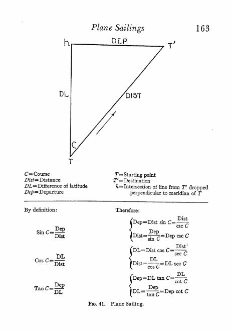
K
DL
Plane Sailings
DLP
163
C= Course
Dist Distance
DL= Difference of latitude
Dep= Departure
1"= Starting pointT'= Destination
h Intersection of line from T droppedperpendicular to meridian of T
By definition:
Cos
Dist
Dist
TanC= PepDL
Therefore:
DepDist=-^;=Dep esc C
sm C *
\
FIG. 41. Plane Sailing.

164 Plane Sailings
II. Spherical (earth's true shape used) considers: Course,
Distance, Diff. Lat., Departure, Diff. Long.
Types: Parallel, Middle Latitude, Mercator, Great
Circle, Composite.Solved by: Methods similar to those for Plane.
Plane Sailings
Plane sailings can be solved by plane trigonometry and
logarithms as indicated in Figure 41, using Bowditch Table
32 for logs o numbers and Table 33 for logs of functions
of angles. It will be seen that there are two or more formulas
for the solution of each side of the triangle to provide for
the various combinations of data given and to be found.
The two commonest problems are: first, given course and
distance, to find difference of latitude and departure; sec-
ond, given difference of latitude and departure, to find
course and distance. In the latter problem, the formulas are
not suitable for long distances.
A shorter way is to use the traverse tables. Bowditch Table
3 gives Diff. Lat. and Dep. for each unit of distance from
1-600 under each degree of Course.
The simplest way, and one sufficiently accurate for
yachtsmen, consists in laying down the various given terms
by scale upon a position plotting sheet and then measuringthe required terms.
A Single calculation is all that is usually called for.
The Traverse problem arises when a ship has made an
irregular track sailing on several different courses. It con-
sists in finding the difference of latitude and departure for
each course and distance by the traverse tables and reducing

Parallel Sailing 165
all to a single equivalent course and distance. This is done
by tabulating the amount of miles made good to north or
south and to east or west on each course; adding up each
of the four direction columns; taking the algebraic sum of
the north and south totals for Diff. Lat. and of the east andwest totals for Dep.; and finding in the traverse table the
course and distance corresponding to this Diff. Lat. and
Dep. This resulting course and distance can then be drawnon the plotting sheet from the starting point and will showthe D. R. position at the end of the irregular track.
Spherical Sailings
Parallel sailing problems come up when a ship's course
is due east or west. There is no change in latitude and all
the distance covered is departure. The problem is to find
the Diff. Long, corresponding to the Dep. This may be done
by logs using the formula (see Dutton, Chap. 1):
Diff. Long. = Dep. sec L
Or, if it is desired to find the amount of departure necessary
to reach a certain longitude:
Dep. = Diff. Long, cos L
It may be more convenient to use Bowditch Table 3. Diff.
Long, will be found in minutes of arc or should be con-
verted thereto as the case may be. The labels of the table
should now be imagined changed as follows:
Course Lat.
Dist. * Diff. Long.Lat. Dep.
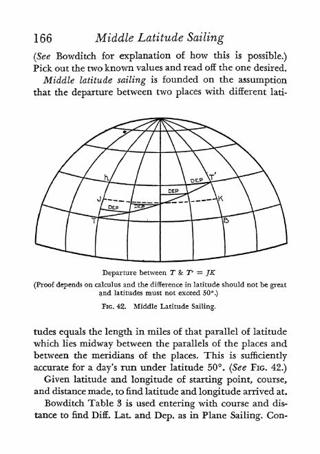
166 Middle Latitude Sailing
(See Bowditch for explanation of how this is possible.)
Pick out the two known values and read off the one desired.
Middle latitude sailing is founded on the assumptionthat the departure between two places with different lati-
Departure between T & T' = JK
(Proof depends on calculus and the difference in latitude should not be greatand latitudes must not exceed 50.)
PIG. 42. Middle Latitude Sailing.
tudes equals the length in miles of that parallel of latitude
which lies midway between the parallels of the places andbetween the meridians of the places. This is sufficiently
accurate for a day's run under latitude 50. (See FIG. 42.)
Given latitude and longitude of starting point, course,
and distance made, to find latitude and longitude arrived at.
Bowditch Table 3 is used entering with course and dis-
tance to find Diff. Lat. and Dep. as in Plane Sailing. Con-

Mercator Sailing 167
verting minutes to degrees, etc., this Diff. Lat. is applied to
latitude left to give latitude arrived at.
The two lats. are now averaged to find Mid. Lat.
The problem thus becomes one in parallel sailing and
Table 3 is used with the same changes of labels as described
for parallel sailing, as follows:
Entering with Mid. Lat. (Course) and Dep. (Lat.) we
find Diff. Long. (Dist.). Convert minutes to degrees, etc.
Applying to longitude left gives longitude arrived at.
Given latitude and longitude of both starting point and
point reached, to find course and distance made good.
Subtract lesser latitude from greater to get DifL Lat. and
convert to minutes.
Average the two latitudes to find Mid. Lat.
Combine the two longitudes to find Diff. Long and
convert to minutes.
Entering Table 3 with Mid. Lat. (Course) and Diff. Long.
(Dist.) we find Dep. (Lat.).
Entering Table 3 with Diff. Lat. (Lat.) and Dep. we find
course and distance.
When the places are on opposite sides of the equator,
this method is not applicable.
Mercator sailing is used when the distance involved is
greater than can be accurately handled with middle latitude.
As previously described, a Mercator chart has parallel
meridians. The result is that the farther one goes from the
equator, the more unnaturally extended' are the parallels
of latitude between any two meridians. Proportions are
kept right because the meridians between parallels of lati-
tude become more and more extended. Expressing it in
another way:

168 Mercator Sailing
Globe map:
Long, degrees become shorter toward pole.
Lat. degrees stay same.
Mercator chart:
Long, degrees stay same toward pole.
Lat. degrees become longer.
The length of the meridian as thus increased on a Mer-
cator chart between equator and any given latitude, ex-
pressed in minutes as measured on equator, constitutes the
number of Meridional Parts corresponding to that latitude.
Bowditch Table 5 gives meridional parts or increased lati-
tudes for every minute of latitude between and 80.Given course and distance from a known position we
wish to know latitude and longitude arrived at. This is
accomplished as follows:
1. Use Table 3 entering with course and distance andfind figure in Lat. column, which is difference of latitude
expressed in nautical miles or minutes of arc. (Or use logs
and equation Diff. Lat. Dist. cos C.)
2. Reduce above to degrees and minutes.
3. Apply above to latitude left (adding if course was
northerly, subtracting if southerly) and obtain latitude
arrived at.
4. When both the place left and place reached are onthe same side of the equator, look up in Table 5 the me-
ridional parts for each latitude and subtract the smaller
quantity from the greater. When the places are on oppositesides of the equator, similarly look up the two quantitiesbut add them. In each case the result is the meridional
difference of latitude or ra.

Great Circle Sailing 169
5. Table 3 is now used with the following two substitu-
tions of title:
Lat. m.
Dep. Diff. Long.
Enter table with course and m (Lat. column) and take out
Difference of Longitude (Dep. column) expressed in min-
utes. (Or use logs and equation: Diff. Long. = m tan C, if
C is not near E. or W.)6. Reduce above to degrees and minutes.
7. Apply above to longitude left (adding if course was
away from Greenwich, subtracting if toward) and obtain
longitude arrived at. (If over 180, subtract from 360 and
change name.)In case we require course and distance by rhumb line
between two given positions which are far apart:
1. By subtraction find difference of latitude.
2. By subtraction find difference of longitude.
3. Use Table 5 and find m as described in 4 above.
4. Find course by using logs and equation:
Diff. Lone,tan C = m
5. Find distance by using logs and equation:
Dist. = Diff. Lat. sec. C.
Great Circle Sailing
The shortest distance over the earth's surface between
two places is that measured along the great circle which
passes through them. Generally speaking, the economy of

170 Great Circle Sailing
the great circle over the rhumb line is greatest for longdistances at high latitudes when the course lies more E. or
W. than N. or S.
Every great circle, excluding the equator and meridians,
cuts successive meridians at a different angle. To keep a
ship on a great circle course, therefore, would require con-
stant change of heading. As this is impracticable, the course
is changed at regular intervals such as every 150 or 300 miles.
Thus the ship really follows a series of rhumb lines.
Every great circle track, if extended around the earth,
will lie half in the northern and half in the southern
hemisphere.The Vertex of a great circle track in one such hemisphere
is that point which is farthest from the equator, or has the
highest latitude.
A great circle track between two places in, say, the north-
ern hemisphere will everywhere be north of the rhumbline between these places. This is because a rhumb line is
a spiral, concave toward the pole, which approaches but
never reaches the pole. On a Mercator chart, then, a great
circle track between two places in the northern hemisphere
appears as a curve above the straight rhumb line joiningthe places.
Great Circle or Gnomonic Charts are charts on which
great circle courses will appear as straight lines. They are
constructed for a given area of the globe by passing a plane
tangent to the center of the area and then projecting by
rays from the globe's center all features of the area onto
the plane. As the plane of every great circle passes throughearth's center, and as one plane always intersects another
in a straight line, the projected great circles will be straight
lines.

Great Circle Sailing 171
The Polar Chart is a great circle chart for use in highlatitudes where a Mercator is too distorted and spread out.
The meridians are straight lines radiating from the poleand the parallels are circles with the pole as center, increas-
ingly separated from the pole outward. (See Button, Chap.
VI.)
Hydrographic Office Publications 1280-1284 are great
circle charts of the principal oceans. They are spoken of as
on the Gnomonic Projection. The meridians appear as
straight lines converging toward the poles, and the parallels
appear as non-parallel curves, concave toward the poles.
No compass rose can be applied to the whole of such a
chart and latitude and longitude at a particular point must
be determined by reference to nearby meridians and par-
allels. The chart becomes distorted in the longitudes more
removed from the center and so is not satisfactory for navi-
gation. However, it provides the most convenient means for
determining great circle track and distance between points.
The track is always a straight line. An explanation is printedon such charts of how to determine the length of the track
and the course at any point of the track. After selecting a
number of points of the track on the great circle chart, their
latitude and longitude are determined and such points are
then plotted on a Mercator chart. A fair curve is then drawn
through these points and gives the great circle on the
Mercator.
In the absence of a great circle chart, the track, courses,
and distance may be determined by computation. This
rather long process will not be gone into here. A good ex-
planation and method will be found in H. O. 211. A very
easy and rapid method of finding initial course and distance
is provided for in H. O. 214.
172 Composite Sailing
Composite Sailing
This is a combination of great circle and parallel sail-
ing. It is used when the great circle course between two
points passes through higher latitudes than it is thoughtwise to enter. This may be from considerations of ice or
cold or wind. There are three main ways of determining the
track; by gnomonic charts, by computation, or by graphicmethods. (See Bowditch.) An approximation to the shortest
track between the points without exceeding the given lati-
tudes is had by following a great circle between the pointsuntil the limiting parallel is reached, following this parallel
until the great circle is again met, and finally following the
great circle to destination.
The track may be laid on a Mercator chart as follows:
1. Draw the track on a great circle chart.
2. Determine the latitude and longitude of a number of
points of the track.
3. Transfer these points to the Mercator.
4. Draw a smooth curve between them from point of
departure to destination.
5. Discard the portion of the curve which lies north (or
south) of the limiting parallel, retaining the two remaining
portions of the great circle and that part of the limiting par-allel included between their northern (or southern) ends.
Other methods of composite sailing are the following:1. One great circle to a predetermined place; a Mercator
to another predetermined place; and another great circle
to destination.
2. One great circle to the limiting parallel at a given
longitude; another great circle from there to destination.

Dead Reckoning 173
3. One great circle from departure tangent to the limiting
parallel; another great circle from destination tangent to
the limiting parallel; course along parallel between the two
points of tangency. This is the shortest possible compositecourse.
W. S. N. Plotting Charts
A new series of charts or plotting sheets is featured by the
Weems System of Navigation. The charts are designed to
eliminate the sailings calculations. Mercators and great
circles are measured directly. There are four charts in the
series covering all areas from equator to pole.
Dead Reckoning
The working of dead reckoning involves a combination
of the methods of traverse and middle latitude sailing. See
Chap. 29 for appropriate form of table to be kept and the
following summary from Bowditch:
"When the position of the vessel at any moment is re-
quired, add up all the differences of latitude and departure,
and write in the column of the greater, the difference
between the northing and southing, and the easting and
westing. Apply the difference of latitude to the latitude of
the last determined position, which will give the latitude
by D. R., and from which may be found the middle latitude;
with the middle latitude find the difference of longitude
corresponding to the departure; apply this to the longitude
of last position, and the result will be the longitude by'D. R."
Button says, p. 95: "In modern practice nearly all navi-
gators do their dead reckoning work graphically."

174 Current
Current
Current is a broad term covering anything and every-
thing that causes a discrepancy between the D. R. positionfor a given instant and a fix from celestial observation for
the same instant. Button summarizes as follows:
1. Foul bottom of ship.
2. Unusual condition of trim.
3. Error of patent log or revolution curve.
4. Inaccurately known compass error.
5. Poor steering.
6. State of wind and sea.
7. Observation errors.
8. Real ocean currents or streams.
9. Tidal currents found along the coast.
The Estimated Position
Either a Computed Point (Chap. 15) or a D. R. positionwhich has been revised for Current is called an Estimated
Position.
Real Ocean Currents
The Set of a current is the direction toward which it is
flowing.
The Drift of a current is its velocity in knots (nauticalmiles per hour).
The two usual problems which arise may be solved bytraverse tables or trigonometry but simple graphic solu-
tions on the chart with a protractor are satisfactory, as
shown (after Button) on pages 176-179, following.

Current 175
Current does not affect the ship's speed through the water.
Wind, weather, waves, etc., however, do so.
In case the current is directly against or directly with the
ship's course, the algebraic sum of speed and current gives
speed over ocean floor.
r~. . , Distance in milesTime required =bpeed over bottom in miles per hour
-,, . , Distance in miles
Speed over bottom m miles per hour =r Time consumed

FIG. 43. First Current Problem.
176-
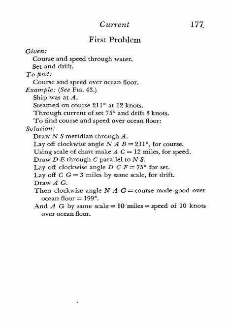
Current 177
First Problem
Given:Course and speed through water.
Set and drift.
To find:
Course and speed over ocean floor.
Example: (See FIG. 43.)
Ship was at A.
Steamed on course 211 at 12 knots.
Through current of set 75 and drift 3 knots.
To find course and speed over ocean floor:
Solution:
Draw N S meridian through A .
Lay off clockwise angle N A B 211, for course.
Using scale of chart make A C 12, miles, for speed.Draw D E through C parallel to AT S.
Lay off clockwise angle D C F = 75 for set.
Lay off C G = 3 miles by same scale, for drift.
Draw A G.
Then clockwise angle N A G = course made good over
ocean floor =199.And A G by same scale = 10 miles = speed of 10 knots
over ocean floor.

Fio. 44. Second Current Problem.178 -

Current 179
Second Problem
Given:
Set and drift.
Speed of ship
Course you desire to make good.
To find:
Course you must steer.
Speed you will make on it.
Example: (See FIG. 44.)
Ship is at A.
Current has set 75 and drift 3 knots.
Ship's speed= 12 knots.
Course to be made good =195.To find course to steer and speed attainable on it:
Solution:
Draw N S meridian through A.
Lay off clockwise angle N A B = 195, for course to be
made good.
Lay off clockwise angle N A C = 75, for set.
Using scale of chart make A D = 3 miles, for drift.
Erect a meridian D Nf
.
With D as a center and a radius of 12 miles by same scale,
sweep an arc cutting A B at E.
Draw D E.
Then clockwise angle N' D E = course to steer = 206.
And A E by same scale = 10.2 miles = 10.2 knots speed
attainable on course to be made good.

22. The Day's Work
BEGINNINGA VOYAGE, a good departure should
be taken while landmarks are still in view. This be-
comes the start of the dead reckoning which with new de-
partures from fixes by celestial navigation is kept up till
the voyage is completed. The patent log, having been putover, is read and recorded on taking departure. If an en-
gine revolution counter is used it is read and time noted.
The following summarizes the required daily work at sea
(see Button):
Dead Reckoning is carried forward from one well-
determined position to the time of next observation or
fix. Comparison of D. R. and fix gives "current" since last
fix. Log or engine revolution counter is read at each obser-
vation.
Compass Error is determined at morning and afternoon
observations of the sun and, if possible, whenever the course
is changed.
Sun Observations should be made in forenoon and after-
noon when on the prime vertical providing the altitude is
then over 10; otherwise, as near prime vertical as possiblewith altitude exceeding 10. Sun should also be observed
at local apparent noon or for ex-meridian.
Fixes from at least two stars should be made at morningand evening twilight. Other combinations as star and planet,
planet and moon, etc., can be used.
Additional work., in case of failure to obtain A. M. fix or
other of the above observations, consists in daylight sights180-

The Day's Work 181
of sun and moon, or sun and Venus, for a fix; latitude byPolaris may be done at dawn; or a running fix from two sunsights may be all that can be obtained.
Chronometers are wound at a certain time each day andnote made of any changes between them.Radio time signals are received daily, if possible, and
chronometer correction noted.
Reports of work are made to the captain at 8 A. M., noon,and 8 P. M. These include:
Position by D. R.
Position by observation.
Set and drift of current.
Deviation of compass.Course and distance made good since last report.Course and distance to destination.
Any necessary change in course.
Ship's run (at noon since last noon).

23- Essential Equipment(For Celestial Navigation and Dead Reckoning)Absolute minimum
Sextant
Chronometer
Watch
Magnetic CompassAzimuth Circle or Pelorus
Patent LogNautical Almanac
Dead Reckoning Altitude and Azimuth Table (H. 0. 21 1)
Bowditch (H. O. 9)
Plotting sheets and charts
Dividers, parallel rulers, triangle, magnifying glass
Notebook, pencils, eraser, pencil sharpener
Also importantRadio
Gyro Compass
Engine revolution counter
Telescope or binoculars
Stop-watch
Second-setting 24 h. face watch
Course protractor
Tables of Computed Altitude and Azimuth (H. O. 214)Noon-Interval Tables (H. O. 202)Star Identifier (H. O. 2102-B)Celestial Globe (preferred to above)Collected Correction Tables (see Chap. 3)
182*

24. Practical Points
General
ONBEGINNING a voyage, the navigator must pro-
vide himself with the latest ocean charts of the regionsto be sailed, and note the date of the last corrections. All
weekly "Notices to Mariners" should be obtained whichhave appeared subsequent to this date and any applicabledata therein should be entered on the charts. The material
necessary for coastwise navigation and piloting such as tide
and current tables, coast pilots, light lists and large scale
charts of coasts, harbors, etc., are not part of celestial navi-
gation and are mentioned here only in passing. The essential
equipment for taking and working sights should be checkedover carefully and put in order.
The navigator's watch (pocket or wrist) should be kepton zone time for ease of translation to G. C. T.
The best standard of accuracy attainable in position find-
ing may be expressed as a circle with a radius of one mile
around the fix point on the chart. This is practically perfectwork. It may occasionally be bettered, but is often not at-
tained. Refraction, faulty observation, rolling ship, errors
in time, etc., all make the actual practice at times more of
an approximation than an exact procedure. Experience
brings knowledge as to how accurate a given fix will prob-
ably prove to be.
The height of eye for the place on the ship which will
usually be used by the navigator in taking sights should be
accurately determined after the ship is loaded.

1 84 Practical Points
Sextant (General)
The minimum altitude for reliable observations is 10
and 15 is still better.
On a rolling vessel, stand on the center line to avoid
changes in height of eye.
When a distant haze makes the horizon poor, it may befound better by lowering the height of eye.
In clear weather, increasing the height of eye makes for
greater accuracy.
Index error of the sextant should be checked each timeit is used.
"Bringing a body down to the horizon" is especially con-
venient for a star or planet sight but may also be well usedfor sun or moon. Set sextant at zero. Look through it di-
rectly at body. Loosen index arm and slowly push it forward.A second image of body will appear to drop from the origi-nal. Lower the aim of sextant, abandoning original imageand following this second one which is in the mirror side
of the horizon glass. Continue pushing index arm forwardand lowering aim to keep the mirror image of body in viewuntil horizon appears in clear half of glass. Clamp sextantat an approximate contact and adjust to exact contact byvernier screw.
After one preliminary observation, a sextant may be set
ahead of a body's altitude on even 5' or 10' intervals of arc
and several times of contact noted. Then use the average of
these altitudes and times.
The author heartily endorses the following, written byJ. T. Rowland in Yachting, March 1941: "I would ratheruse one good shot, in which I feel confidence, than introduce

Practical Points 185
the error which may be present in a doubtful one. My sys-
tem, therefore, is to take a series of sights until I get one in
which I have faith and then use that. True this calls for
some discernment on the part of the navigator but it is sur-
prising how quickly one can develop an aptitude for 'calling
one's shots/
It is more important to be exact with time than with the
altitude. Ten seconds of time error can throw a position off
2i/miles whereas 10" of arc error will alter the result only
about 1/5 mile.
When reading sextant, have the eye directly over the
marks to avoid error of parallax between vernier and limb.
Focus the telescope on some distant object before screw-
ing it in to sextant frame.
Eye-strain is less if both eyes are open when taking sights.
Between sights at twilight it may be helpful to close the
eye used on sextant when going into the light to consult
chart or read sextant. Returning to take another observation
the sextant eye will then be in better shape for work.
Start with tangent screw about halfway from its two ex-
treme positions so as to allow plenty of room for finer
adjustment.
Sextant (Care of)
On small boats it is well to have a short lanyard attached,
with an eye splice to fit over the wrist, in order to avoid
dropping the sextant overboard.
The sextant is a delicate instrument and must not be
dropped, bumped or jarred. It should be kept from sudden
changes of temperature or moisture as far as is possible* It

1 86 Practical Points
should be in its case with index arm clamped when not
working and the case should be attached to some safe placein the boat.
After use in wet weather the mirrors should be dried
with chamois, linen or lens paper, not with silk.
When dirty, the arc and vernier may be cleaned withammonia or sperm oil.
When the graduations of the sextant arc become dim, a
paste of gritless lamp black and light oil may be smearedover arc and wiped off. This will clean the marks and also
make them more easily read.
Sextant (Index Error)
Graduations of arc and vernier are continued somewhatto right of zero of arc and of zero (index) of vernier.
When a star's reflected image is brought into coincidence
with the star seen directly, or when in daylight the reflected
sea horizon is matched with the direct view of it, the sextant
should read zero. If, however, zero of vernier lies to left of
zero of arc (called "on"), the error is + and its correction
will have to be subtracted. Or if zero of vernier lies to rightof zero of arc (called "off"), the error is and its correction
will have to be added.
In the latter case, the reading of how much it is "off" is
done in a special way. Read the vernier as usual, lookingto left till a vernier line is found coinciding with an arc
line, and count the minutes and seconds to this vernier line.
Then subtract this amount from the maximum reading of
the vernier. The result will be the amount of error.
Another method of measuring index error is by measur-

Practical Points 1 87
ing the apparent diameter of the sun. This is done by first
bringing the upper limb of reflected image tangent to lowerlimb of direct image and reading the sextant; then bringinglower limb of reflected image tangent to upper limb of di-
rect image and again reading the sextant. Mark readingwhen on the arc as and when off as +. The algebraic sumof the two readings will be Index Correction.
If a series of such observations is made, add up the read-
ings of each pair without signs and divide by 2 to get sun's
diameter. Look in N. A. for sun's semidiameter for the date
and multiply by 2 for true diameter. Pick from the series
that pair which most closely approximates this true value.
Use this pair for Index Correction.
Artificial Horizon
One may use a pie plate of ink set in a box 18" x 18" x 8"
without a cover.
Sit back of and above plate in line with sun and its imagein ink.
With sextant, bring real sun image down to ink image.Former will be in right-half of horizon mirror, latter in left.
Though hard to find at first, lateral swinging will locate it.
In forenoon bring real sun image, lower limb, tangentto upper limb of ink image. Former will rise till transit,
separating the images unless pulled down by tangent screw.
In afternoon, bring real sun image, lower limb, tangentto upper limb of ink image. Former will fall, causing over-
lap, unless raised by tangent screw.
Read the (double) sextant altitude of observation; applyI. C. to this; divide by 2.

188 Practical Points
Correct for refraction, parallax and semidiameter but notfor height of eye.
Result is true altitude.
Sun
Swing in the strongest shade glass before observing sun.
If this cuts off too much light use the medium shade glass,
etc. If sun is looked at directly with too little protection it
will make observation impossible for several minutes.
Test for index error after shade glasses are in place since
they may be responsible for the error.
Hold sextant vertically, aimed toward the horizon be-
neath the sun. Move index arm from zero position slowlyforward till sun's image appears in mirror of horizon glassand continue till lower edge of image is about tangent to
horizon seen through clear half of horizon glass. Set the
clamp screw (or release lever).
Determine vertical position of sextant by swinging it in
an arc around line of sight axis and watching sun imageswing in a curve convex to horizon. When image is lowest
is when sextant is vertical. At this point adjust the tangentscrew to bring sun's lower edge just tangent to horizon. Atthis instant call out "Mark," which signals your assistant
to take the time. If alone, punch the starter of a stop-watchand proceed as described in Chapter IL
Owing to refraction when the sun's center is actually in
horizon, the lower limb appears to be about one semi-diameter above horizon.
The usual correction tables include correction for sun's
semidiameter only when lower limb is used. If unusual

Practical Points 1 89
circumstances should permit only an observation of upperlimb, as when sun is partly obscured by clouds or even in
an eclipse, proceed as follows:
Apply I. C. to sextant altitude. Then subtract 2 X sun's
semidiameter for closest date found in N. A. (This gives
sextant altitude of lower limb.) Finally, apply usual cor-
rections from Tables A, B, and C for refraction, parallax,
semidiameter and dip, to obtain corrected altitude.
Moon
A bright moon may illuminate an otherwise dim hori-
zon so that an altitude of the moon or a star nearby may be
obtained.
At times with the moon about half-full, care must be
taken to choose the limb whose upper or lower edge ex-
tends through what would be the vertical diameter of the
moon if full.
Planets
Since navigational planets are brighter than stars they
usually appear first at evening twilight and disappear last
in the morning. Hence they can be observed when horizon
is clearest and should be used when available.
When Venus is over 2 hours of R. A. distant from the
sun, it may be seen in daylight. Calculate its approximatealtitude and azimuth in advance. Set the sextant for this
altitude and look through it with the medium telescope
attachment in the direction of the calculated azimuth.
Lenses and mirrors must be clean. A distinct white disc will

190 Practical Points
be found and exact altitude can then be obtained. Later,
knowing where to look, Venus can be seen with the naked
eye.
Stars
A way for timing star sights is as follows:
1. Start stop-watch at first observation.
2. Read stop-watch at 2nd. observation and record.
3. Read stop-watch at 3rd. observation and record.
4. Stop stop-watch on an even minute of chronometer.
5. Subtract total stop-watch reading from chronometer
as in #4 for time of first observation.
6. Add stop-watch reading of #2 to above for time of
second observation.
7. Add stop-watch reading of #3 to time of first ob-
servation for time of third observation.
Some use the following method for observing a star:
Invert sextant set at zero, aim at star, push index arm for-
ward till horizon is brought up approximately to star, clampsextant, invert again and make final fine adjustment. This
prevents starting to observe one star and ultimately makingcontact with another.
When observing a star, it is well to get its approximate
bearing to aid in subsequent identification if doubt should
exist.
The writer obtained a perfectly satisfactory altitude of
Capella an hour before midnight 29 October, 1936, whena full moon and clear air made the horizon as distinct as
could be desired.

Practical Points 191
Morning twilight is a better time for star sights, other
things being equal, than evening. This is because the navi-
gator may, by getting up a little earlier, pick out what stars
he intends to use from the total display with no doubt of
their identity, and then keep them in sight until the horizon
has become sufficiently sharp for measuring their altitudes.
Twilight is shortest in the tropics and increases with lati-
tude.
When working two or three star sights it is best to putthe data in parallel columns and work across the page. Bythis is meant figuring one item for each before going on to
the next item, such as altitude, declination, hour angle, logs,
etc. This is easier and errors show up more readily.
Avoid the use of the confusing inverting telescope. In
poor light it is better to work without any telescope.
Latitude
In using sextant for meridia:n altitudes remember: Image
goes up as body goes up.
Turning vernier screw down on left side increases alti-
tude reading, and pulls body's image down.
Hence, while watching for body to transit: So long as
you have to keep turning vernier screw down on left to
keep body on horizon, the body is rising, and first dip of
body below horizon without having turned vernier screw
is start of body's fall after transit.
As declination and latitude get farther apart, conditions
become more favorable for finding latitude and less so for
longitude.In working the sun for reduction to meridian, t should

1 92 Practical Points
not exceed in minutes the number of degrees in sun's
meridian zenith distance.
Reduction to the meridian is not nearly so reliable as
the meridian sight. Any error in D. R. longitude makes t
in error and as the formula uses t2 the error becomes much
greater. When observed altitude is over 60 the procedureis also less reliable.
A rough observation of Polaris may be made as stars beginto fade at morning twilight and this can be made accurate
when horizon has become clearer.
Polaris has been observed for latitude during an electrical
storm at night.
Azimuth
When Mizar of the Big Dipper or Ruchbah of Cassiopeiaare either above or below Polaris, the latter bears true N.
and can be used for compass error.
"When it is desired to swing ship using sun azimuths,
it is convenient to use a graph laid out on coordinated (cross-
section) paper. The interval 5 P. M. to 5:40 P. M., for in-
stance, may be laid off on a horizontal line, a square for
each minute, numbering every 5-minute square. The verti-
cal scale, centered on the left-hand end of the horizontal
scale, is graduated to the degrees of azimuth, with two
squares for each degree. The azimuths taken from the tables
for 5 P. M, and 5:40 P. M. (using, as an example, lat. 49 N.,
and declination 17 SO7
N.) are then plotted and a line
drawn connecting them. The azimuth for "any intermediate
time is now readily available. Suppose the azimuth for
5: 1 1 P. M. is desired: Run up the vertical line of 5: 1 1 until

Practical Points 1 93
it intersects the azimuth line, then run horizontally to theleft to the intersection with the vertical scale, where theazimuth is indicated as N. 87 15' W." (Chapman, p. 225.)
See Button, p. 347, for method of obtaining a curve of
magnetic azimuths by H. O. 214.
Line of Position
It will sometimes be possible to get a line of positionwhich is parallel to the course from a body abeam. Whenthis is plotted it will at once show which way the ship is
being set from the course and how far.
A line of position can sometimes be obtained which is
perpendicular to the course from a body dead ahead orastern. This gives a good check on the run.
If a body is observed on the prime vertical (due E. or
W.) the line obtained runs N. and S. and is unaffected byany error in the D. R. latitude.
The meridian altitude gives a line running E. and W.which is independent of any longitude error.
If only a single Summer line is obtainable, it may be of
great value combined with a terrestrial bearing to give a
fix; or the position on a line near shore may be told from
soundings; or if the line is parallel to shore it will tell
distances from land; or, finally, if it is perpendicular to
shore the captain will know what to look for.
Plotting
Draw lines of position for a fix before labeling them so
letters will not obscure intersection.
Above a line of position put the time it was obtained,
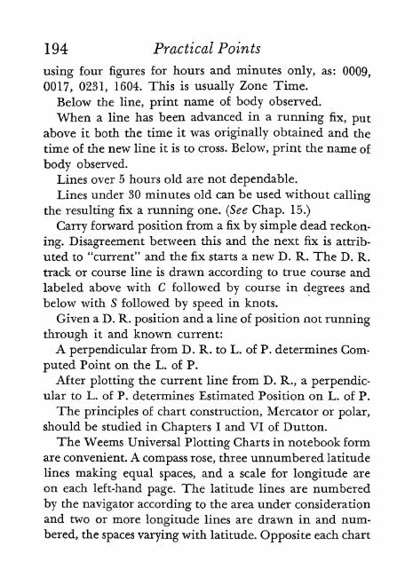
194 Practical Points
using four figures for hours and minutes only, as: 0009,
0017, 0231, 1604. This is usually Zone Time.
Below the line, print name of body observed.
When a line has been advanced in a running fix, putabove it both the time it was originally obtained and the
time of the new line it is to cross. Below, print the name of
body observed.
Lines over 5 hours old are not dependable.Lines under 30 minutes old can be used without calling
the resulting fix a running one. (See Chap. 15.)
Carry forward position from a fix by simple dead reckon-
ing. Disagreement between this and the next fix is attrib-
uted to "current" and the fix starts a new D. R. The D. R.
track or course line is drawn according to true course and
labeled above with C followed by course in degrees and
below with S followed by speed in knots.
Given a D. R. position and a line of position not running
through it and known current:
A perpendicular from D. R. to L. of P. determines Com-
puted Point on the L. of P.
After plotting the current line from D. R., a perpendic-ular to L. of P. determines Estimated Position on L. of P.
The principles of chart construction, Mercator or polar,
should be studied in Chapters I and VI of Button.
The Weems Universal Plotting Charts in notebook form
are convenient. A compass rose, three unnumbered latitude
lines making equal spaces, and a scale for longitude are
on each left-hand page. The latitude lines are numbered
by the navigator according to the area under consideration
and two or more longitude lines are drawn in and num-
bered, the spaces varying with latitude. Opposite each chart
Practical Points 1 95
is a blank page for observational data. Thus all the record
is kept easily available and the marking up of regular charts
is avoided.
If plotting sheets are not available, the following sug-
gestion is made by Chapman in Piloting, Seamanship andSmall Boat Handling (1940, p. 220), "A simple methodof laying off intercepts in a work book is to employ the
rulings of the page as meridians of 1' of longitude each,
crossing them with the parallel of D. R. latitude. From anyintersection of a meridian with this parallel draw a line at
an angle equal to the degree of latitude. This line becomesa distance scale on which each space between rulings is 1
mile or F of latitude available for use in laying off the inter-
cepts and in measuring the latitude difference betweenthe fix and D. R. latitude. In effect we have a miniatureMercator chart."

25* Navigator's Stars
and Planets
THEREARE MANY good books by which the student
can become familiar with stars and with the constel-
lations or groups of stars whose names date back manycenturies. A somewhat different presentation has been
worked out here for the student navigator. The fifty-four
stars of the regular list in the N. A, are taken up in the
order given there, that is in order of increasing right
ascension from W 5m 25s.7 to 23h l
m 54s.2 (1943). An
arbitrary starting time is chosen but the list may be used
at any later month providing one identification is made.
For each subsequent star is found more eastward and de-
scribed in relation to one or more close predecessors.
It must be remembered that directions are those on the
concavity of the celestial sphere. Curved lines must be
imagined in following them. For instance, all directions
of arcs of great circles radiating out from the North star
are south. A small circle around the pole star followed
clockwise as we observe it is always leading east, counter-
clockwise west.
As each star to be described is farther eastward on the
celestial sphere, it is more elevated either later in the same
evening or at the same time later in the year. The whole
sphere appears to be revolving counterclockwise aroundthe North star as a center (due north and as high in degrees
196-
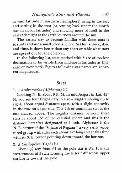
Navigator's Stars and Planets 197
as your latitude in northern hemisphere) rising in the east
and setting in the west (or coming back under the North
star in north latitudes) and showing more of itself in the
east each night as the earth journeys around the sun.
The easiest way to become familiar with these stars is
to study and use a small celestial globe. Set for latitude, date
and time, it shows better than any chart or table what stars
are spread out for the observer.
In the following list, stars marked with * are of too low
declination to be visible from mid-north latitudes as Chi-
cago or New York. Figures following star names are appar-
ent magnitudes.
Stars
1. a Andromedae (Alpheratz) 2.2
Looking N. E. about 9 P. M. in mid-August in Lat. 42
N. you see four bright stars in a row slightly sloping up to
right, about equal distances apart, with a slight concavity
in the row on upper side. The 4th or southmost star is the
one named above. The angular distance between these
stars is about 15 of the celestial sphere and this is the
distance hereafter designated as 1 unit. Alpheratz is the
N. E. corner of the "Square of Pegasus," a very easily recog-
nized group with sides each about 15 long and at this time
with its S. E. corner pointing down toward the horizon.
2. ft Cassiopeiae (Caph) 2.4
About 1/2 way from #1 to the pole star is #2. It is the
westernmost of 5 stars forming the letter "W" whose upper
surface is toward the pole.

198 , Navigator's Stars and Planets
3. Ceti (Deneb Kaitos) 2.2
About 3 units S. by E. of # 1 .
4. 8 Cassiopeiae (Ruchbah) 2.8
4th. star to the E. in the "W" mentioned in #2.
*5. a Eridani (Achernar) 0.6
About 2^ units S. by E. of #3.
6. a Arietis (Hamal) 2.2
li/ units S. of 2nd. star from N. in row of 4 mentionedin#l.
*7. Eridani (Acamar) 3.4
units N.E. of #5.
8. aPersei(Marfak)1.9The first or northmost of row of 4 mentioned in #L
9. a Tauri (Aldebaran) 1.1
About 2 units S. E. of 2nd. in row of 4 mentioned in #1is small dim cluster: the Pleiades. Proceed 1 unit more to
#9. Red tinged.
10. ft Orionis (Rigel) 0.3
2 units(
S. S. E. of #9. The S. W. corner of a roughrectangle-Orionwhose length is N. and S.
11. a Aurigae (Capella) 0.2
li^ units E. by S. of #8.
12. y Orionis (Bellatrix) L71 unit S. E. of #9. The N. W. corner of Orion.
13. c Orionis (Alnilam) 1.8
The middle of 3 stars in center of Orion which are
slanting S. E. and N. W.

Navigator's Stars and Planets 199
14. a Orionis (Betelgeux) 0.5 to 1.1
The N. E. corner of Orion.
*15. a Argus (Canopus) -0.9
3 units S. S. E. of #10.
16. a Cants Majoris (Sirius) 1.6
units S. E. of #13. Our brightest star.
17. e Canis Majoris (Adhara) 1.6
1 unit S. by E. of #16. Westernmost of 3 close stars.
18. a Canis Minoris (Procyon) 0.5
units E. of #14.
19. /? Geminorum (Pollux) 1.2
li/units N. of #18. Stars 14-18-19 make a right-angled
triangle whose hypotenuse faces N. W.
*20. e Argus 1.7
li^ units S. E. of #15. Westernmost of 3 making equi-
lateral triangle.
*21. X Argus (Al Suhail al Wazn) 2.2
2 units E. N. E. of #15.
*22. /3 Argus (Miaplacidus) 1.8
ls/4 units S. of #21. Stars 15-21-22 form an equilateral
triangle.
23. aHydrae(Alphard)222 units E. S. E. of #18.
24. aLeonis(Regulus)l.3
I]/2 units N. N. E. of #23. Stars 18-23-24 make a right-
angled triangle whose hypotenuse faces N. by W.

200 Navigator's Stars and Planets
25. a Ursae Majoris (Dubhe) 2.
3^ units N. by E. of #24. The upper extremity of "big
dipper" away from handle. It and stari/
unit S. constitute
the "pointers" which point to the pole star. Seven stars in
whole dipper. Handle curves down.
26. ft Leonis (Denebola) 2.2
units E. byN. of #24.
*27. a' Cruets (Acrux) 1.6
114 unit E. N. E. of #22. Southmost star in "Southern
Cross."
*28. y Cruets 1.6
yz unit N. of #27. Top star in "Southern Cross/'
*29. ft Crucis 1.5
\/$unit S. E. of #28. East star in "Southern Cross."
30. e Ursae Majoris (Alioth) 1.7
3rd. in handle of "big dipper" counting tip of handle
as 1st.
31. Ursae Majoris (Mizar) 2.4
2nd. in handle of "big dipper" next to tip.
32. a Virginis (Spica) 1.2
214 units S. E. of #26.
*33. Centauri 2.3
units S. S. E. of #32 or 2 units N. E. of #27.
34. a Bootis (Arcturus) 0.2
2 units S. by E. of tip of handle of "big dipper." Stars
26-32-34 make an equilateral triangle with sides 2i/3 units
long.

Navigator's Stars and Planets 201
*35. a Centauri (Rigel Kentaurus) 0.3
1 unit E. by N. of #27.
36. p Ursae Minoris (Kochab) 2.2
\yz units N. by E. of tip of handle of "big dipper." Theupper extremity of "little dipper" away from handle. Sevenstars in whole dipper, the tip of handle being pole star 1
unit away. Handle curves up,
37. a Coronae Borealis (Alphecca) 2.3
li/s units E. N. E. of #34.
38. 8 Scorpii (Dschubba) 2.5
. 2i/2 units E. S. E. of #32. Center one of 3 similar in row
1/2unit long going N. and S.
39. a Scorpii (Antares) 1,2
3 units E. S. E. of #32. Reddish.
*40. a Trianguli Austmlis 1.9
1 unit S. E. of #35.
41. -7 Ophiuchi m (Sabik) 2.6
1 unit N. E. of #39.
*42. \ Scorpii (Shaula) 1.7
unitS. E. of #39.
43. a Ophiuchi (Rasalague) 2.1
2 units S. E. by E. of #37.
44. y Draconis (Etamin) 2.4
units E. of tip of handle of "big dipper.
*45. c Sagittarii (Kaus Australis) 2.
unit E. S. E.of#39.

202 Navigator's Stars and Planets
46. a Lyrae (Vega) 0.1
1 unit S. E. by S. of #44. In conditions named in #1 this
is the bright star almost in zenith.
47. o- Sagittarii (Nunki) 2.1
2 units E. of #39.
48. a Aquilae (Altair) 0.9
2i/2 units S. E. by S. from #46.
*49. aPavonis 2.1
2 units S. E. of #45.
50. a Gygni(Deneb) 1.3
H/ units E. N. E. of #46. Stars 46-48-50 make a right-
angled triangle with hypotenuse facing E. by S.
51. tPegasi (Enif)2.5
2 units E. of #48.
*52. aGruis(AlNa'ir)2.2
li/s units N: E. by E. of #49.
53. a Piscis Australis (Fomalhaut) 1.3
3 units S. of S. W. star of "Square" (see #1).
54. a Pegasi (Markab) 2.6
S. W. star of "Square."
Planets
In contrast to stars which usually twinkle, planets shine
with a steady light. Instead of being a mere point of light,a navigational planet shows a distinct disc when viewedwith binoculars. This disc can sometimes be seen with the
unaided eye. The planets are always within a belt 8 each

Navigator's Stars and Planets 203
side of the ecliptic (projection of plane of the earth's orbit
or apparent path of the sun). Venus, Mars and Jupiter are
brighter than any star. Certain individual characteristics
of the four navigational planets are as follows:
Venus is the brightest heavenly body after the sun and
moon. It is 12 times as bright as Sirius, the brightest star.
Its orbit lies nearer the sun than our earth's and so it is
never seen more than about 47 of angular distance from
the sun. For the same reason it shows phases, like the moon,
which can be easily detected with binoculars and which
vary its magnitude or brightness from 4 to 3. It ap-
pears as either a "morning" or "evening star." It gets around
the sun in 225 of our days. When its R. A. differs by over
2 hours from that of the sun, Venus may be seen in daylight
if above horizon.
Mars shines with a reddish light and varies in magnitudefrom 3 to +2. It must be distinguished from Aldebaran
(#9) and Antares (#39) which are both reddish stars of
magnitude 1 and near the ecliptic. Its orbit lies next outside
the earth's and its year is 687 of our days. Much speculation
has been given to the question of whether Mars is inhab-
ited by intelligent beings.
Jupiter is a brilliant white planet of 2 magnitude. Its
orbit lies next outside those of the asteroids and its year is
almost 12 of our years. Its diameter is over 12 times that of
the earth and it has 1 1 moons. Usually 4 of these can be
seen with binoculars. Roemer in 1675 made a remarkably
close estimate of the speed of light from observations of the
eclipses of these moons.
Saturn is yellowish white and of magnitude to +LOnly two stars are brighter than this planet: Sirius (#16)

204 Navigator's Stars and Planets
and Canopus (#15). It is more easily mistaken for a star
than are the other three we have described. But when seen
in a good telescope, it is a unique heavenly body because
of its "rings." These are layers of billions of whirling par-ticles extending out from its equator. When seen on edge
they are a thin line but as the position changes they are
seen to be broad bands. There are also 10 moons. Saturn's
orbit lies next outside Jupiter's and its year is 29J/2 of our
years. Consequently, we do not notice much shift of its
position among the stars between one year and the next.
It is so much less dense than the earth that it would float
on water.
26. Reference Rules
for Book Problems
ONTHE PAGE FOLLOWING is Table 19, given for
occasional reference only. Learning its contents with-
out understanding each step would be the very sort of thing
in the study of navigation which this Primer attempts to
prevent. When doing actual work at sea the labeling of
angles east or west is usually self-evident or easily deter-
mined from a rough diagram of the sort described in Chap-ter 2. The interested student, however, will want to work
out problems for practice which he finds in textbooks. Then
it is a more difficult matter to imagine oneself transported
to the bridge of a ship, perhaps on the other side of the
world, and to visualize the given situation accurately. The
table provides a means of checking work done on such
problems.
205-

TABLE 19
RULES FOR TIME AND ANGLES
206

27. Finding G. C. T.
and Date
DESIGNEDFOR THE BEGINNER, Table 20 is to
be used in checking his calculations of time. It ex-
presses the first part of Table 19 in another way and like
that table will be found more useful in doing book prob-lems than necessary in actual work. It gives at a glance the
G. C. T. and date from a 12-hour face chronometer at anyhour of a 12-hour face watch on zone time in any time zone.
Until watches and chronometers are generally equippedwith 24-hour dials, this matter will always be a potential
source of confusion and error. Meanwhile the table may be
used as follows:
Suppose on July 4 you are in Long. 135 E. with no chronometer error.
(Table 6 on page 41 shows this to be zone minus 9.) Suppose it is morningand navigator's watch on zone time reads 8 o'clock. Wanted G. C. T. anddate. Look in vertical column of 9 zone for figure 8 in A. NT. section.
Follow horizontally till central chronometer column is reached and figure11 found. This is, of course, chronometer face. Look at overprinting in the
triangle where you started and find "C + 12 Day before." Apply this to
chronometer, 11 + 12 23, and subtract one from date: G. C. T. is 23&
00m 00s on 3 July.When the time is between 12 and 1, an additional step is necessary. Say
zone time is 12:30 P. M. in zone + 7. This means half an hour after 12
A. M. (upper half). Follow vertical column down to the figure 1 (lower
half). Then follow horizontal to center, finding C = 8. Subtract 30 minutes.
C then becomes 7:30. The overprinting in zone group is C -f 12. 7:30 4-
12 = 19:30 = G. C. T. with no change of date.

TABLE 20
FOR FINDING G. C. T. AND DATEFrom a 12-hr, face chronometer at any hour of
a 12-hr, face watch on zone time in any time zone.
YA L N G.- G-* -* L O N G.
ZONES ZONLS* It'll +10 *9 *6 *7 *6 -5*4 *
V A T C H+1 -1 -a -3 -4 -5 -6 -7 -8 -9 -10 -11 -fc
C_V A T C H
M
4 5 6 7 8 9 10 IMS,
6 T-N 8 9 10 II II
6 7\8(y 10 11 I;
6789 10 II
7 8
67897 6 9 10
3 4 5 *6 7 8 9 10 11
2.34567 891011345674 5
3456769 10 II \t/[
345678945675 6
10 11
i a 3 4 a 6 7 e> 9 10 n la
*lNCRUSt DATE. BY ONt SWUNG WtST DLCRE.ASL DATE, er ONL SAILING LAST -*
Each figure in central vertical column gives corrected chronometer read-
ing for zone time in same horizontal row.
12 in zone groups is only an instant not a second over. You must followvertical column down or up to other half to get succeeding hour of 1.
1 in zone group includes the minutes of preceding and succeeding hour.2 to 11 inclusive in zone groups include the minutes of the succeeding
hours.
Overprinting in the eight triangles tells what to do with the correctedchronometer time in order to get G. C. T. and Date.
208-

28. Abbreviations
a. Altitude difference or interceptC. Course.
C. C.'
Chronometer correction.
C. F. Chronometer face.
C. O. Chronometer at observation.
C. S. Chronometer at stop time.
C-W Chronometer minus watch.
co-L Co-latitude.
Corr. Correction.
cos Cosine.
cot. Cotangent.
C. P. Computed point,
esc. Cosecant.
D. D. Daily difference,
d. or Dec. Declination.
Dep. Departure.
Dev. Deviation.
Diff. or D. Difference of.
Dist. Distance.
D. R. Dead Reckoning.E. East.
E. P. Estimated position.
Eq. T. Equation of Time.
G. Greenwich meridian.
G.A. T. Greenwich Apparent Time (or G. A. C. T.).
G. C. T. Greenwich Civil Time.
G. H. A. Greenwich Hour Angle.209-
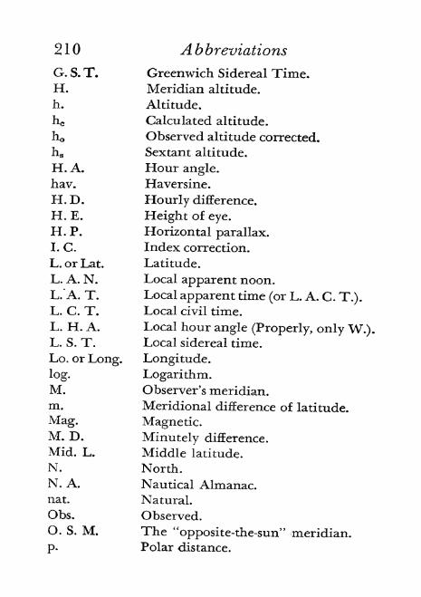
210 A b breviations
G. S. T. Greenwich Sidereal Time.H. Meridian altitude.
h. Altitude.
hc Calculated altitude.
h Observed altitude corrected.
hs Sextant altitude.
H. A. Hour angle.hav. Haversine.
H . D . Hourly difference.
H. E. Height of eye.
H. P. Horizontal parallax.I. C. Index correction.
L. or Lat. Latitude.
L. A. N. Local apparent noon.L."A. T. Local apparent time (or L. A. C. T.).L. C. T. Local civil time.
L. H. A. Local hour angle (Properly, only W.).L. S. T. Local sidereal time.
Lo. or Long. Longitude.
log. Logarithm.M. Observer's meridian.m. Meridional difference of latitude.
Mag. Magnetic.M. D. Minutely difference.
Mid. L. Middle latitude.
N. North.N. A. Nautical Almanac.nat, Natural.
Obs. Observed.O. S. M. The "opposite-the-sun" meridian.
p. Polar distance.

Abbreviations 211
P. Parallax.
p.s. c. Per Standard Compass.
R. Refraction.
R. A. Right ascension.
R. A. M. O Right ascension of mean sun.
R. W. Ran stop-watch.
S. South.
S. D. Semidiameter.
sec. Secant.
sin. Sine.
t. Meridian angle. (E. or W. < 180)tan. Tangent.Var. Variation.
W. West or Watch.
z. Zenith distance.
Z. Azimuth.
Zn Azimuth on 360 scale.
O Sun.
( Moon.
Planet.
# Star.
9 Venus.
$ Mars.
U Jupiter.
Saturn.
T First Point of Aries or Spring Equinox.^ Difference from.
> Greater than,
Less than.
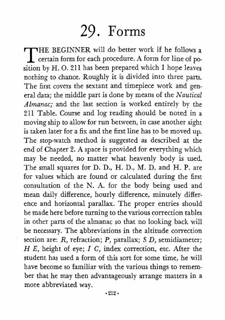
29 Forms
THEBEGINNER will do better work if he follows a
certain form for each procedure. A form for line of po-
sition by H. O. 211 has been prepared which I hope leaves
nothing to chance. Roughly it is divided into three parts.
The first covers the sextant and timepiece work and gen-
eral data; the middle part is done by means of the Nautical
Almanac; and the last section is worked entirely by the
211 Table. Course and log reading should be noted in a
moving ship to allow for run between, in case another sight
is taken later for a fix and the first line has to be moved up.
The stop-watch method is suggested as described at the
end of Chapter 2. A space is provided for everything which
may be needed, no matter what heavenly body is used.
The small squares for D. D., H. D., M. D. and H. P. are
for values which are found or calculated during the first
consultation of the N. A. for the body being used and
mean daily difference, hourly difference, minutely differ-
ence and horizontal parallax. The proper entries should
be made here before turning to the various correction tables
in other parts of the almanac so that no looking back will
be necessary. The abbreviations in the altitude correction
section are: R, refraction; P, parallax; S D, semidiameter;
H E, height of eye; I C, index correction, etc. After the
student has used a form of this sort for some time, he will
have become so familiar with the various things to remem-
ber that he may then advantageously arrange matters in a
more abbreviated way.212-

Forms 213
There are three other forms, designed for H. O. 211,
which may be found occasionally convenient. A form for
line of position by the cosine-haversine method with time
and altitude azimuth should be useful when Bowditch
alone is available. The remarkable, though at present rather
impractical, formulas for Aquino's Fix may be easily ap-
plied in a fprm here offered.
A form for Dead Reckoning, two for Middle Latitude
and two for Mercator sailing, should help the beginner.Forms for Day's Run and Day's Current show how each
may be worked either by logs or by Table 3.
When a word is followed by a different word in paren-
theses, as Dep. (Lat.), it means: find the first in the column
headed by the word in parentheses.

LINE OF POSITION
H. O. 211
(Form by J. F.)
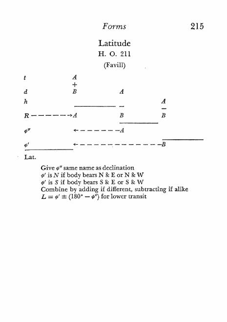
Forms 215
Latitude
H. O. 211
(Favill)
* A
d B A
h A
R >A B B
Lat.
B
Give <t>" same name as declination
0' isN if body bears N & E or N &W0' is S if body bears S & E or S & WCombine by adding if different, subtracting if alike
L = <P' (180* <P") for lower transit

216 Forms
LongitudeH. O. 211
(Hinkel)
90 = 89 60' .0
d
l.u.
l.v.
l.CSC 2 1A t = fc -r 2 =l.csc y% t = & found in A givesJ/2 * = & X 2 == & combined with
G.H.A., gives
Longitude
When d & L have same name:
p = 90 - d
When d & L have opposite names:
# = 90 + d

Forms 217
Altitude Azimuth
H. 0. 211
(Hinkel)
90 = 89" 60' .0
l.sec 2i/2 Z = &*2 =
l.sec 14 Z = & found in B gives
1/2 Z = & X 2 =
When d & I have same name:
p = 90 - d
When d & L have opposite names:
p= 90 + d

218 Forms
Line of PositionH. O. 9
(Bowditch: Cosine-Haversine Altitude, and Time and
Altitude Azimuth)
Z from? pole
Aquino's Fix
(Form modified by J.F.)
From Simultaneous Altitude and Gyro Azimuth
Long. Lat.

Forms 2 1 9
Middle Latitude Sailing
FOR COURSE AND DISTANCE
Latitude Latitude Longitude
Loi
o /
o /

220-

Forms 221
Mercator Sailing
TOR COXIRSE AND DISTANCE
Latitude Longitude
From '
/' M.P. ' "
To' "
M.P. ' "
DL ' " m
log
-log
FOR POSITION REACHED
Lo,
Ltan. l.sec.
log
log
Ltan.
m log
log

222 Forms
Day's Run
Latitude Longitude
By obs. or D.R. noon yesterday*
By obs. or D.R. noon today*
DL N DLo
By Logs and Mid. Lat. Sailing
DLo log
Lm l.cos,
(Dep.) log
DL log log
Course ,l.tan. l.sec.
In Quad
Dist. log
By Traverse Table and Mid. Lat. Sailing
DLo (Dist,) 1
Lm (CnJ.1 |Table3: Dep. (Lat.)

Forms 223
Day's Current
(Given D.R. run in miles: DL * and Dep. )
Latitude Longitude
Position by obs. noon yesterdayN &
Run by D.R. noon today DL * DLoPosition by D.R. noon today
Position by obs. noon today
Current
from Nbelow /
DL "(miles) Z>Z,0z/minutesN\ of Lo )
By Logs and Mid. Lat. Sailing
By 1 raverse Table and Mid. Lat. Sailing
= DL,, D.R . (DiM.)enter
- above
i 1 _ , , fCourse.
Dep., Cur. (Dep.).
,=Set
_= Drift (m.p.h.)
30. Problems
INCONTRAST to most texts, this Primer has not in-
eluded problems with its explanations of the various
procedures of celestial navigation. The reason for this is
that it was hoped the student would more quickly acquiresound principles and a clear understanding of the subject
as a whole if he were spared the detail of computationswhile first reading the book through as a sort of surveycourse. Plenty of problems can be found in Bowditch or
Dutton or other texts and short-cut systems. Best of all
are the problems one goes out and sets for himself. How-
ever, a few illustrative examples will now be given of the
more important procedures. I have taken data for the
meridian latitude sights from Bowditch, 1933 edition, and
for the time conversions from the 1939 Nautical Almanac.
The rest are my own. The fact that most of my sights were
taken from known positions may lessen interest but has
the advantage of showing the degree of accuracy of the
results.
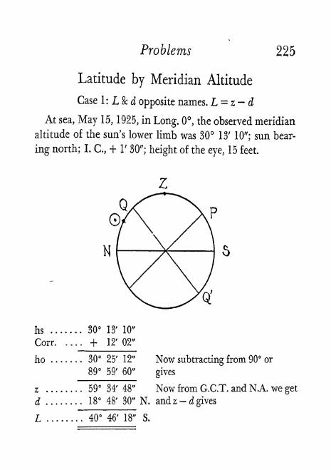
Problems 225
Latitude by Meridian Altitude
Case 1: L & d opposite names. L = z - d
At sea, May 15, 1925, in Long. 0, the observed meridian
altitude of the sun's lower limb was 30 13' 10"; sun bear-
ing north; I. C., + 1' 30"; height of the eye, 15 feet.
Q'
hs 30 13' 10"
Corr. . . . . + 12' 02"
ho 30 25' 12" Now subtracting from 90 or
89 59' 60" gives
z 59 34' 48" Now from G.C.T. and N.A. we get
d 18 48' 30" N. andz - d gives
L 40 46' 18" S.

226 Problems
Latitude by Meridian Altitude
Case 2: L & d same name and L>d.L=z+dAt sea, June 21, 1925, in Long. 60 W., the observed
meridian altitude of the sun's lower limb was 40 04'; sun
bearing south; I. C., + 3' 0"; height of the eye, 20 feet.
hs 40 04' 00"
Corr. . . . . + 13' 21"
ho 40 17' 21"
89 59' 60"
.0
z 49" 42' 39"
d 23 26' 48" N. and z + d gives
L 73 09' 27" N.
Now subtracting from 90 or
gives
Now from G.C.T. and N.A. we get

Problems 227
Latitude by Meridian Altitude
Case 3: L & d same name and d > L. L d z
At sea, April 14, 1925, in Long. 140 E., the observed
meridian altitude of the sun's lower limb was 81 15' 30";
sun bearing north; I. C.,-
2' 30"; height of the eye, 20 feet.
hs 81 15' 30"
Corr. . . . . + 9' 00"
ho 81 24' 30" Now subtracting from 90 or
89 59' 60" gives
z 8 35' 30" Now from G.C.T. and N.A. we getd 9 10' 48" N. and d - z gives
L~
35' 18" N.
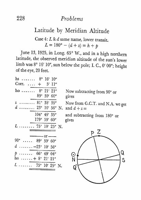
228 Problems
Latitude by Meridian Altitude
Case 4: L & d same name, lower transit.
L = 180 -(d + z)
= h + p
June 13, 1925, in Long. 65 W., and in a high northernlatitude, the observed meridian altitude of the sun's lowerlimb was 8 16' 10", sun below the pole; L C., 0' 00"; heightof the eye, 20 feet.
hs ....... 8 16' 10"
Corr. .... + 5' II"
8 21' 21" Now subtracting from 90 or89 59' 60" gives
z ........ 8r 38' 39" Now from G.C.T. and N.A we getd ..... ... 23 10' 56" N. and d + z =
104 49' 35" and subtracting from 180 or179 59' 60" gives
L ..... ... 75 10' 25" N.
90" ..... 89 59' 60"
d ....... -23 10' 56"
p ..... . . 66 49' 04"
ho ...... + 8 21' 21"
L ..... . . 75 10' 25" N.

Problems
Latitude by Phi Prime, Phi Second
(H. 0.211)
229
At anchor, in evening of August 21, 1935, in Lat. 42
12' N., Long. 87 48' W., observed star Deneb, bearingabout ENE, as follows: sextant altitude 58 56'; I. C. 0' 0";-
H. E. 12 feet; G. C. T. 22 August, P 39m 20s.
L 42 12' N*Beginning with the 1936 N. A., the G, H. A. of stars is given for each
day of the month, thus shortening this calculation by 1 step.
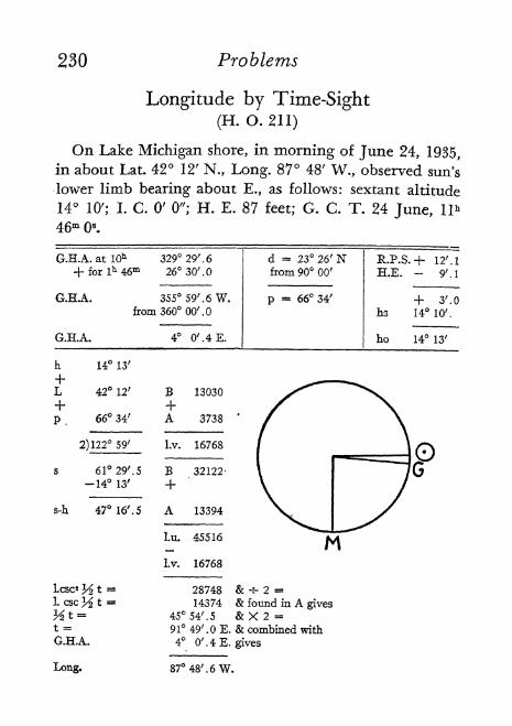
230 Problems
Longitude by Time-Sight(H. 0.211)
On Lake Michigan shore, in morning of June 24, 1935,
in about Lat. 42 12' N., Long. 87 48' W., observed sun's
lower limb bearing about E., as follows: sextant altitude
14 10'; I. C. 0' 0"; H. E. 87 feet; G. C. T. 24 June, 11*
46m s.
1. CSC% t '
y*t~t =G.H.A.
Ixsng.
28748 & -s- 2 =14374 & found in A gives
45 54'. 5 &X2 =91 49'. E. & combined with4 0'. 4 E. gives
87 48'. 6 W.

Problems 231
Altitude Azimuth
(H. 0.211)
At anchor, in morning of June 16, 1936, in Lat, 42
12' N., Long. 87 48' W., observed sun's lower limb, bear-
ing about E., as follows: sextant altitude 33 31' 10"; I. C.
0' 0"; H. E. 12 feet; G. C. T. 16 June, 13* 32m 6s.
d = 23 21'. 6 N R.P.S. + 14'. 5
from 9000'.0 H.E. - 3'. 4
66 38'.4 + 11'. 1
hs 33 31'. 2
ho 33 42'. 3
h 33 42'. 3 B 7993
L 42 12' B 13030
+p 66 38'. 4 Lv. 21023
2) 142 32'. 7
s 71 16'. 3 B 49346
-66 38'. 4 +
s-p 4 37'. 9 B 142
Liu 49488
Lv. 21023
L sec' 1A Z = 28465 & -s- 2
1. sec y% Z = 14232 & found in B gives
y2 Z = 43 54' & X 2 =Z = N. 87 48' E.
(Merely a coincidence that this = Longitude)

232 Problems
Azimuth by H. O. 214
Make 5 columns headed by: Decimals, t} d> L> and Base.
Data taken from Sun problem, which follows:
* 19 47.7 E., d 23 26'.8 N., L 42 12' N.
Enter these as degrees and decimals in left column.
Use H. 0. 214, Vol. V, entering with t 19, d 23, L 42
(the next lower whole degrees) on page for L and d of same
name and get Base Z 134 .3.
Enter this at top of the four remaining columns.
Use H. 0. 214 with base d fe L but 1 greater t
" " " " " tkL "1
"d
^ d jo Land write resulting azimuths under Base in proper columns.
Find differences between above and Base which give
changes for 1 increase of each variable.
Mark results( + )
or( ) according as azimuth is increas-
ing or decreasing with the higher entry figures.
Convert each to minutes of arc.
Multiply each by the decimal fraction of a degree bywhich corresponding quantity of given data exceeds
quantity used to get Base.
Mark results( + )
or( )
as before.
Take algebraic total for correction.
Apply to base Z in 5th column for Z (on 180 system).
Convert to Z on 360 system = Zn.
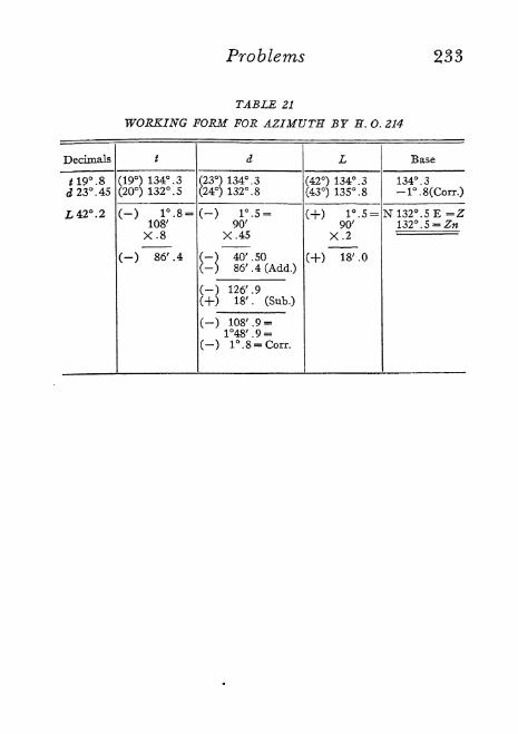
Problems 233
TABLE 21
WORKING FORM FOR AZIMUTH BY E.O. 214

234 Problems
Line of Position from Sun
(H. O. 211)
At anchor, in forenoon of June 21, 1936, in about
Lat. 42 12' N., Long. 87 47' W., observed sun's lower
limb, bearing about SSE, as follows: sextant altitude 64
52' 10"; I. C. 0'/A
; H. E. 12 feet; G. C. T. 21 June, 16h
33m 34s.
(See diagram on opposite page)

Problems 235
Line o Position from Sun(H. O. 9)
Previous problem worked by Cosine-Haveisine method,
with "time and altitude" azimuth formula.
t 19 47'. 7
L 42 12' N
d 23 26'. 8 N
18 45'. 2
1. hav. 8.47052
+1. cos. 9,86970
H-
1. cos. 9.96258
1. hav. 8.30280
8 n. hav. .02008
+n. hav. .02654
Lsin. 9.52975
1. cos. 9.96258
z 24 56' 15" -4- z n. hav. .04662
from 89 59' 60"
he 65 3'. 7
ho 65 4'. 2
1. sec. 10.37506
Zl. sin. 9.86739
Z = 47 287
(from S. toward E.)a . 5 mile toward
(This method requires 9 consultations of the tables, whereas H.O. 211 requires
but 7.)

236 Problems
Line of Position from Moon(H. 0.211)
At anchor, in evening of October 29, 1936, in Lat. 42
12' N., Long. 87 48' W., observed moon's lower limb,
bearing about ENE, as follows: sextant altitude 7 58' 40";
I. C. 0' 0"; H. E. 12 feet; G. C. T. 29 October, 23h 4m 1s!
(See diagram on opposite pdge.)
t 92 17'
d 16 6'.2NA 34.5
B 1738 A 55694
1772. 5A->B 55289
KL
he
ho
97 49' N42 12' N
37'
9 5'. 8
9 5'. 9
405
B 55289
B 24816
-<-A 80105
A 1772
550
A 1222
a . 1 mile toward Zn 76 28'
(This calculation illustrates the exception to Rule 1: since t > 90, take
K from bottom; and the exception to Rule 2: since K is same name as
and > L, take Z from top. Whenever the first exception applies, the secondwill also be called for. See Fig. 40, page 136.)
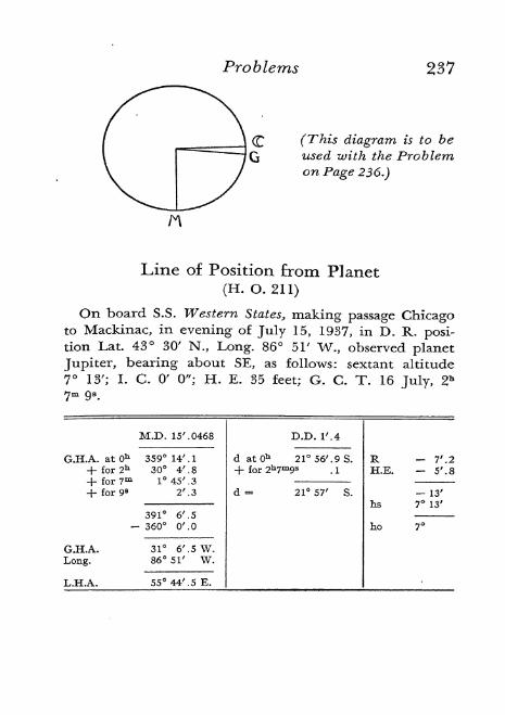
Problems 237
(This diagram is to be
used with the Problemon Page 236.)
Line of Position from Planet
(H. 0.211)
On board S.S. Western States, making passage Chicagoto Mackinac, in evening of July 15, 1937, in D. R. posi-tion Lat. 43 30' N., Long. 86 51' W., observed planet
Jupiter, bearing about SE, as follows: sextant altitude
7 13'; I. C. 0' 0"; H. E. 35 feet; G. C. T. 16 July, 2*
7m 9 s.
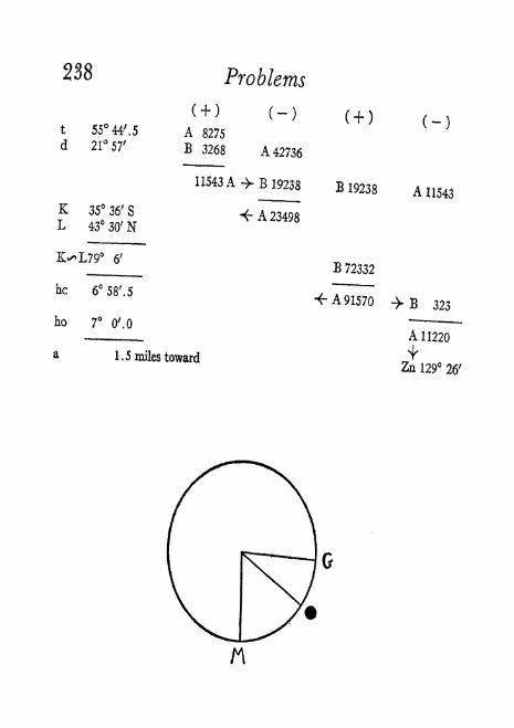
238 Problems
t 55 44'. 5
d 21 57'
K 35 36' S
L 43 30' N
K>L79 6'
he 6 58'. 5
ho 7 O'.O
a
A 8275
B 3268 A 42736
11543 A -> B 19238
4- A 23498
1.5 miles toward
B 72332
A 91570
A 11543
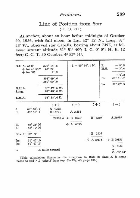
Problems 239
Line of Position from Star
(H. O. 211)
At anchor, about an hour before midnight o October
29, 1936, with full moon, in Lat. 42 12' N., Long. 87
48' W., observed star Capella, bearing about ENE, as fol-
lows: sextant altitude 51 51' 40"; I. C. 0' 0"; H. E. 12
feet; G. C. T. 30 October, 4h 53m 31 s.
KL
heho
53 58'. 44556M
60 21' N42 12' N
18 9'
51 47'.
51 47'. 5
A 9218B 15771 A 14355
24989 A -> B 8259
<- A 6096
B 8259 A 24989
B 2216
-<- A 10475 ->- B 20856
.5 miles toward
A 4133
Zn 65 24'
(This calculation illustrates the exception to Rule 2: since K is same
name as and > L, take Z from top. See Fig. 40, page 136.)

(For Problem on Page 239) (For Aquino's Fix)
Aquino's Fix
At anchor, in evening of June 20, 1936, in Lat. 42 12'
N., Long. 87 48' W., observed star Vega as follows: sextant
altitude 41 16' 30"; simultaneous gyro azimuth 70 50';
I. C. 0' 0"; H. E. 12 feet; G. C. T. 21 June, 2* 7m 9s.
(As I had no gyro, this azimuth was actually determined by calculation,
and the above is merely to illustrate the method which follows.)
38 43' 1. sec 10777 1. tan 9 . 90397 C = 20 33' . 5
1. sec 38436 4-t 65 37' . 7 E. -<- 1. esc 4054
G.H.A. 22 10'. 7 W. b. 1. tan 0.28833 b = 62 46'
Long. 87 48'. 4 W.240-
Lat. 42 12'. 5 N.

Problems 241
Fix from Two Stars *
(H. O. 214)
In evening of Nov. 2, 1941, in D. R. position Lat. 42 15'
N., Long. 87 42' W., observed stars as follows:
Capella: bearing about N. E. by N., sextant altitude 11
30' 00", G. C. T. Nov. 3, Oh lm 30s
.
Deneb Kaitos: bearing about S. E. by E., sextant altitude
1 1 04' 50", G. C. T. Nov. 3, Oh 3m 22s
.
In each case: I. C. 0' 0", H. E. 12 feet.
ALTITUDE CORRECTIONS
hs
RH.E.
ho
Deneb Kaitos
11 04' .8
(-) 4' .9
H 3' .4
10 56' .5
* A practice sight from known position, 42 12' N., 87 48' W., on Lake
Michigan shore, using an imaginary D.R. position to illustrate the method.

242 Problems
5
FIG. 45. Fix bv H. 0. 214, D. R. Position. (See opposite page.)
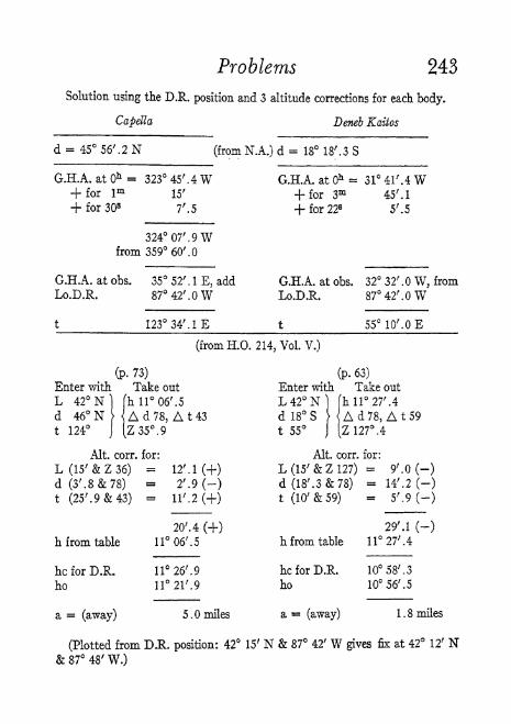
Problems 243
Solution using the D.R. position and 3 altitude corrections for each body.
Capella Deneb Kaitos
d = 45 56'. 2 N (from N.A.) d = 18 18'. 3 S
G.H.A. at Oh = 323 45'. 4W G.H.A. at 0* = 31 41'. 4 W+ for 1* 15' + for 3m 45'. 1
+ for 30s7'. 5 + for 22s 5'. 5
324 07'. 9 Wfrom 359 60'.
G.H.A. at obs. 35 52' . 1 E, add G.H.A. at obs. 32 32' . W, from
LoJXR. 8742'.OW Lo.D.R. 8742'.OW
t 123 34'. IE t 5510'.OE
(from H.O. 214, Vol. V.)
(p. 73) (p. 63)
Enter with Take out Enter with Take out
L 42 N] (h11 06'. 5 L42N) (hll27'.4
d 46 N)
< A d 78, A 1 43 d 18 S >|A d 78, A t 59
t 124j (Z35.9 t 55
j (z 127. 4
Alt. com for: Alt, corr. for:
L(15'&Z36) = 12M(+) L(15'&Z127) = 9'.0 (-)
d(3'.8&78) = 2'.9(-) d(18'.3&78) = 14'. 2 (-)t (25'. 9 & 43)
= ll'.2(+) t (10'&59) = 5'. 9 (-)
20'.4(+) 29'.1 (-)
h from table 11 06;
. 5 h from table 1 1 27' .4
hcforD.R. 11 26'. 9 hcforDJR. 10 58', 3
ho 11 21'. 9 ho 10 56'. 5
= (away) 5.0 miles a ~ (away) 1.8 miles
(Plotted from D.R. position: 42 15' N & 87 42' W gives fix at 42 12' N87 48' W.)

244 Problems
DLNLb KAIT08
FIG. 46. Fix by H. 0. 214. Assumed Position. (See opposite page.)

Problems 245
Solution using an assumed position and 1 altitude correction for each body.
Capella J)eneb Kaitos
d - 45 56'. 2 N (from N,A.) d - 18 18'.3 S
G.H.A. at Oh = 323 45'.4 W G.H.A. at Oh 31 41'. 4 W+ for l
m '
15' +for 3m 45'. 1
+ for 30s7'. 5 + for 22s 5'.5
324 07'. 9 Wfrom 359 60'.
G.H.A. at obs. 35 52' . 1 E, add G.H.A. at obs. 32 32' . W, from
Lo assumed 88 07' . 9 W Ao give t a\Lo assumed 87 32' . W\whole no.J
t 124 E t 55 E
(from H.O. 214, Vol. V.)
(p. 73) (p. 63)
Enter with Takeout Enter with Takeout
L 42 N) fhll06'.5 L42N) (hll 27'.4
d 46N Ad78 d 18 S Ad78t 124
J (Z35.9 t 55J [Z 127. 4
Alt. corr. for: Alt. corr. for
d (3'. 8 & 78) = 2'. 9 (-) d (18'. 3 & 78)- 14'. 2 (-)
h from table ll^'.S h from table 1127'.4
he for A.P. 11 03'. 6 he for A.P. 11 13'. 2
ho 11 21'. 9 ho 10 56'. 5
= (toward) 18.3 miles a = (away) 16.7 miles
Plotted from A.P. \Fix at / Plotted from A.P.
'
42 N&8807',9WJ 42 12; N & 87 48' W \42 N& 87 32'. W

246 Problems
Identification
(H. O. 127)
At anchor, in evening o May 5, 1937, in Lat. 42 12' N.,
Long. 87 48' W., observed an unknown star as follows:
sextant altitude 39 9' 10"; I. C. 0' 0"; H. E. 12 feet;
azimuth about 99; G. C. T. 6 May, P 32m 4s.
R - T .2
H. E. - 3' .4
- 47T
hs 39 9' .2
ho 39 4' .6
1. Entering H. O. 127 with L 42, Z 100 and h 40, we obtain:
d = 19 .3 and t = 3h 32m
2. t converted to arc = 53
3. Long. 87 48' - 53 = 34 48' = G. H. A. (approximate) at
observation
4. Enter N. A. at "Correction to be added to tabulated
G. H. A. of stars" with G. C. T. lh 32m and obtain
23 3' .8 = increase of G. H. A. since Oh
5. G.H. A. at observation 34 48'
Increase since Ob 23 3' .8
G. H.A. atOh 11 44' .2 W.
6. Look in N. A. "Stars" for May 1937, date 6, to find one
with approximately d 19 18' N. and G. H. A. at Oh
11 44' .2 W. The nearest combination found is
d 19 30' .3 N. with G. H. A. 10 13' .3. This is close
enough and identifies this star as Arcturus.

Problems 247
Time of Sun on Prime Vertical
(H. O. 211)
When declination is less than latitude and the same
name,* the time sun will be due E. or W. may be found as
follows:
Estimate G. C. T. when sun will be on Prime Vertical,
E. or W. as you may desire.
Take d for this G. C. T. from N. A.
Estimate L and Lo in which ship will be at this G. C. T.Find L. H. A.
(f)of sun when on P. V. by the following:
esc d
cscL
sec h
-= csc/z
-=csctsec d
Combine t with D. R. Lo to get G. H. A. of sun on P. V.
Use method for transit to find G. C. T. of this G. H. A.
This G. C. T. will be approximate time (as good as D. R.
Lo) when sun will be on P. V, and longitude sight can best
be made.
The advantage of taking the observation for longitude
at this time is that any ordinary error in the latitude used
will not affect the accuracy of the result.
* If d > L and same name, body never crosses P.V,
If d & L are opposite names and
d < L body crosses P.V. below horizon,
d > L body never crosses P.V.
Required time of sun on P. V., 31 July, 1942, in after*
noon, at D. R. position Lat. 41 46' N., Long. 86 51' W.
Estimated G. C. T. for above: 22h on 31 July.
Declination for this: 18 15' .7 N.

248
By H. O. 211:
dL
18 15'. 7 N41 46'.ON
t 6819'.OW+ Lo 8651'.OW
G.H.A. 155 10'.OWG.C.T. 22h
Problems
A 50404A 17646
A 32758
B 2243
(from)
B 5430
A 3187
To find G.C.T. for this
when G.H.A. =
Add
Add
26m to increase G.H.A. by
56s to increase G.H.A. by
G.C.T. 22h 26m 56s Time of sun on P.V.
For +6 zone and wartime this became 5h 26m 56s P.M.
155 10'
148 26'
6 44'
6 30'
14'
14'
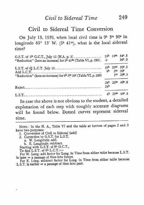
Civil to Sidereal Time 249
Civil to Sidereal Time Conversion
On July 13, 1939, when local civil time is 9h 3m 30s in
longitude 85 15' W. (5h 41m
),what is the local sidereal
time?
G.S.T. of Oh G.C.T., July 13 (NJL p. 3) 19* 19m 54s . 5
"Reduction" (here an increase) for 5* 41m (Table VI, p. 289) . + 56s .
L.S.T. of (4 L.C.T. July 13 19* 20m 50*.5
AddL.C.T 9* 3* 30*
"Reduction" (here an increase) for 9h 3m 30s (Table VI, p. 289) lm 29s . 3
2811 25m 49s . 8
Reject24^
L.S.T 4h 25m 498 ' 8
In case the above is not obvious to the student, a detailed
explanation of each step with roughly accurate diagrams
will be found below. Dotted curves represent sidereal
time.
NOTE: In the N. A., Table VI and the table at bottom of pages 2 and 3
have two purposes:1. Conversion of Civil to Sidereal (add)
2. Correction to G.S.T. for L.S.T.
a. W. Longitude: add.
b. E. Longitude: subtract.
Starting with G.S.T. of Oh G.C.T.,
To find L.S.T. of Oh L.C.T.:,_ n., v T Q T
For W. Long, add factor for Long, in Tune from either table because L.b. 1 .
is later = a passage of time into future.
For E. Long, subtract factor for Long, in Time from either table because
L.S.T. is earlier = a passage of time into past.

250 Civil to Sidereal Time
G. S. T. of 0* G. C. T.
19m 54s. 5.
At Oh L. C. T. we want the
L. S. T. But then O will have
moved through 5h 41m of longi-
tude since first diagram. (Anglebetween dotted meridians is
same as angle between G and
M meridians.) So T will have
also moved 5h 41 m plus a cer-
tain amount. (Table VI.) This
extra amount is because T
"gets around" faster than Oand for a given duration there
are always more units of
sidereal time than of civil
time. For L. S. T. we start our
dotted curve at local meridian
M, thus discarding that part of
dotted curve in first diagramwhich lies between G and M,or 5h 41m . Hence L. S. T. at
Oh L. C. T. is same as G. S. T.
at Oh G. C. T. plus "Reduc-tion" of 56 s for the longitude.This totals 19h 20m 50s
.5.

Sidereal to Civil Time 251
But we must figure for the
L. C. T., when O has moved
9h 3m 30s since second diagram.
Then T will have also moved
9h 3m 30splus a certain
amount. (Table VI.) So we ex-
tend the dotted curve 9h 3m
30s + lm 29 s
.3. Adding this to
L. S. T. of Oh L. C. T. gives
28* 25m 49s.8.
As the last amount is over 24h,
and we do not count sidereal
dates, we discard 24h leaving
L. S. T. = 4h 25m 49s .8 at
L. C. T. 9h 3m 30s.
Sidereal to Civil Time Conversion
On July 13, 1939, when local sidereal time is 4h 25m
49s .8 in longitude 85 15' W. (5* 41-), what is the local
civil time?
G.S.T. of 0* G.C.T., July 13 (N.A. p. 3)19* 19m
"Reduction" (here an increase) for 5* 41m (Table VI, p. 289) . +54S.5
56s.O
L.S.T. of 0. L.C.T. July 13* 20m 50s 5
L.S.T. given (+ 24 for subtracting above) ^on **m w .&
Sidereal time interval since 0* L.C.T ^ 4m 5*.3
Reduction (actual) for 9^ 4m 59S.3 (Table V, p. 287)- lm 293.3
L.C.T.3m 30s
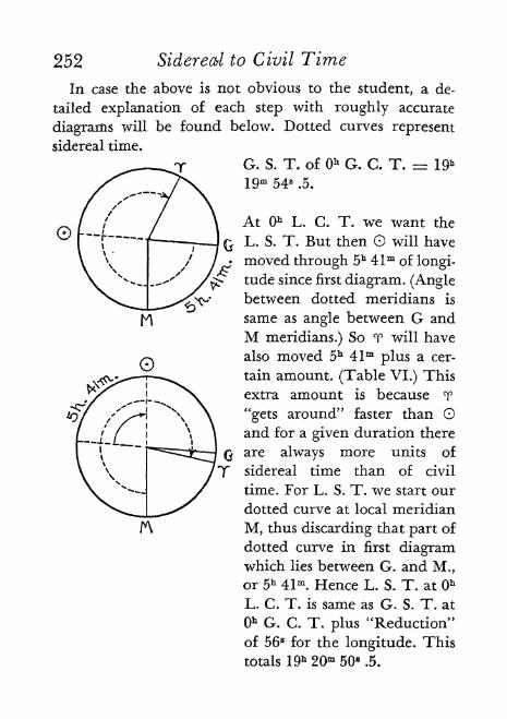
252 Sidereal to Civil Time
In case the above is not obvious to the student, a de-
tailed explanation of each step with roughly accurate
diagrams will be found below. Dotted curves represent
sidereal time.
G. S. T. of Qh G. C. T. 19h
19m 54 s.5.
At Oh L. C. T. we want the
L. S. T. But then O will have
moved through 5h 41m of longi-
tude since first diagram. (Anglebetween dotted meridians is
same as angle between G and
M meridians.) So T will have
also moved 5h 41m plus a cer-
tain amount. (Table VI.) This
extra amount is because T
"gets around" faster than Oand for a given duration there
are always more units of
sidereal time than of civil
time. For L. S. T. we start our
dotted curve at local meridian
M, thus discarding that part of
dotted curve in first diagramwhich lies between G. and M.,
or 5* 41m . Hence L. S. T. at Ob
L. C. T. is same as G. S. T. at
Oh G. C. T. plus "Reduction"
of 56 s for the longitude. This
totals 19*20* 50s.5.

Sidereal to Civil TimeWe know the L. S, T. at the
unknown L. C. T. is 4h 25m
49 s.8. We want to know the
interval in sidereal time be-
tween this L. S. T. and the
L. S. T. of 0* L. C. T. as
shown in second diagram. In
order to subtract 19h 20m 50s.5
from 4h 25m 49s.8 we add 24*
to the latter. (Other combina-
tions may not require this.)
This subtraction gives the de-
sired interval in sidereal time
between L. S. T. at the un-
known L. C. T. and L. S. T.
of Oh L. C. T. It is 9h 4* 59 s.3.
This is a slightly larger quan-
tity than the civil time for the
same duration. To convert it
to civil it must be reduced byan amount l
m 29 s.3 found for
it in Table V. Subtracting this
gives the interval now in civil
time.Itis9b 3m 30 8.
This shows L. C. T. 9h 3m 30 s
at L. S. T. 4* 25m 49s.8.
253

254 Transit
A Uniform Method for More Exact Timeof Local Transit of Any Body
Find G,H.A. (W. or E. to 180) at 0* G.C.T. of date on which local transitis desired and compare with Lo.Rule I, for West Longitude: If G.H.A. (W.) at Oh G.C.T. of date on which
local transit is wanted is < Lo. W., use G.H.A. in calculation as of one datemore.Rule II, for East Longitude: If G.H.A. (E.) at Oh G.C.T. of date on which
local transit is wanted is < Lo. E., use G.H.A. in calculation as of one dateless.
When neither rule applies, use G.H.A. in calculation as of date on whichlocal transit is wanted.When L.H.A. (transit), G.H.A. = Lo. (always expressed as W. to
360 ).
Find G.H.A. of planet or star at Oh G.C.T. of date ds found above and ex-
press as W. or E. to 180. Find G.H.A. of sun or moon on date as found aboveat whatever hour the G.H.A. is closest under Lo. W. to 360. These are start-
ing positions.Calculate the
_angular distance to be timed from body's starting position,
west to its position at transit, adding an east to a west angle if necessary.The appropriate "Correction to G.H.A." table must now be used in each
case (sun, moon, planet or star) to add up the total G.C.T. equal to this an-
gular distance, using correct H. D. for moon or V. p. M. for planet. This givesG.C.T. of local
transit^Apply longitude in time, or zone description with reversed sign, to G.C.T.
for L.C.T. or Z.T, of local transit.

Transit 255
Required: L. Tr. Denebola, June 3, 1939, Lo. 88 30' W.
(G.H.A. (W.) 6/3 0* G.C.T. = 74 03'. 3 = <Lo. W.: Rule I)
When L.H.A. = 0, G.H.A. = Lo. = 88 3(X W.At G.C/L 6/4 Oh
,G.HA =
(-) 75 02;
,5 W.
13 27'. 5 to goN.A. p. 214: Oh 53m represents (-) 13 17'. 2
10'. 3 to go"41 8 " -10'.3
G.C.T. 6/4 Oh 53m 41 s = G. Time of L. Tr.
Lo. W. (-) 5* 54m 00s
L.C.T. 6/3 18h 59m 41 8 = L Time of L. Tr.
Required: L, Tr. Betelgeux, Dec. 9, 1939, Lo. 90 E.
(G.H.A. (W.) 12/9 Oh G.C.T. = 348 51'.
from 350 60'.
G.H.A. (E.)= 11 09'. - <Lo. E.: Rule II)
When L.H.A. = 0, G.H.A. = Lo. = (360-
90) = 270 00'. W.
At G.C.T. 12/8 0*, G.H.A. - 347 51;
.9 W.from 359 60'.
G.H.A. (E.) 1208M (+) 12 08'. IE.
282 08M to go
N.A. p. 216: 18h 45m represents (-) 282 01' .2
6'. 9 to go27 fl .5
"{-)6'.9
G C T 12/8 18h 45m 27 s. 5 = G. Time of L. Tr.
Lo. E. (+) 6h 00* 00B,0
L.C.T. 12/9 Qh 45m 27 8 .5 = L. Time of L. Tr.
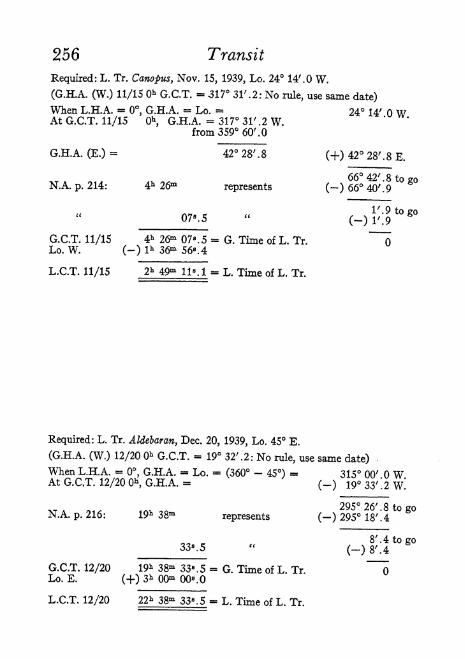
256 Transit
Required: L. Tr. Canopus, Nov. 15, 1939, Lo. 24 14'. W.
(G.H.A. (W.) 11/15 & G.C.T. - 317 31'. 2: No rule, use same date)
When L.H.A. = 0, G.H.A. = Lo. 24 14' WAt G.C.T. 11/15 0*, G.H.A. - 317 31' .2 W,
from 359 60'.
G.H.A. (E.) = 42 28' . 8 (+) 42 28' . 8 E.
66 42' 8 to 20N.A. p. 214: 4h 26* represents (-) 66 40'! 9
G.C.T, 11/15 4h 2&* 07 s. 5 = G. Time of L. Tr
Lo. W. (-) l h 36^ 56s. 4
L.C.T. 11/15 2*49m 11M L. Time of L. Tr.
Required: L. Tr. Aldebaran, Dec. 20, 1939, Lo. 45 E.
(G.H.A. (W.) 12/20 0* G.C.T. = 19 32'. 2: No rule, use same date) -
When L.H.A. - 0, G.H.A. - Lo. - (360 - 45) - 315 00' WAt G.C/T. 12/20 0*, G.H.A. = (_) 19 33'*. 2 W.'
N.A. p. 216: 19* 38m represents (-) 295 18'! 4t0 g
- 8'. 4 to go
G.C.T. 12/20 19* 38m 33 fl .5 - G. Time of L. TrLo. E. (-f) 3h 00* 008 .0
L.C.T. 12/20 22 h 38m 33s. 5 - L. Time of L. Tr.

Transit 257
Required: L. Tr. Saturn, June 1, 1939, Lo. 176 19'. 4 W.
(G.H.A. (W.) 6/1 0* G.C.T. = 222 41'. 8: No rule, use same date)
When L.H.A. = 0, G.HiA. Lo. = 176 19' 4 WAt G.C.T. 6/1 Oh
, G.H.A. = 222 41'. 8 Wfrom 359 60'.
G.H.A. (E.) - 137 18'. 2 (+) 137 18' .2 E.
(H.A.Va,p.M. = 15'.0369)^IF^ to go
N.A. p. 159 : 20h represents (-) 300 44' . 4
12 53'. 2 to go" 161 51m (-) 12 46'. 8
6'. 4 to go25*. 5 (-)6'.4
G.C.T. 6/1 20h 51m 25s. 5 = G. Time of L. Tr.
Lo. W. (-) ll h 45m 17 s. 6
L.C.T. 6/1 Qh 06m 07a 9 =
Required: L. Tr. Moon, Jan. 28, 1939, Lo. 15 26'. 3 W.
(G.H.A. (W.) 1/28 Oh G.C.T. = 99 07'. 9: No rule, use same date)
When L.H.A. = 0, G.H.A. = Lo. = 15 26'. 3 W.At G.C.T. 1/28 19h G.H.A. = (-) 14 40' .2 W.
46M to go(H.D. = 14 29'. 3)N.A. p. 133: 03m represents (-)43'.4
2' . 7 to go
G.C.T. 1/28 19h 03m 11 B .0 = G. Time of L. Tr.
Lo. W. (-) Ih 01m 45".2
L.C.T. 1/28 18h Olm 25 fl .8 - L. Time of L. Tr.
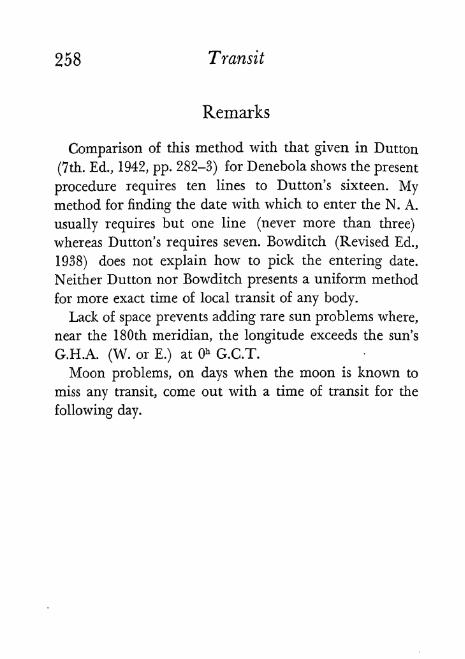
258 Transit
Remarks
Comparison of this method with that given in Button
(7th. Ed., 1942, pp. 282-3) for Denebola shows the present
procedure requires ten lines to Button's sixteen. Mymethod for finding the date with which to enter the N. A.
usually requires but one line (never more than three)
whereas Button's requires seven. Bowditch (Revised Ed.,
1938) does not explain how to pick the entering date.
Neither Button nor Bowditch presents a uniform method
for more exact time of local transit of any body.
Lack of space prevents adding rare sun problems where,
near the 180th meridian, the longitude exceeds the sun's
G.H.A. (W. or E.) at Oh G.C.T.
Moon problems, on days when the moon is known to
miss any transit, come out with a time of transit for the
following day.

SelectedBibliography
Published by the U. 5. Government Printing Office, Washington, D. C.:
The American Nautical Almanac. Issued annually.
The American Air Almanac. Each section covers four months.
Published by the U. S. Hydrographic Office, Washington, D. C.:
9. American Practical Navigator. Originally by Nathaniel Bowditch,
LL.D. Revised Edition of 1938.
66. Arctic Azimuth Tables. For declinations to 23 and latitudes 70-88.
71. Azimuths of the Sun ("Red"). For declinations to 23 and latitudes
to 70.
120. Azimuths of Celestial Bodies ("Blue"). For declinations 24-70 and
latitudes to 70.
127. Star Identification Tables. For latitudes and altitudes to 88 and
azimuths to 180.
202. Noon-Interval Tables.
205. Radio Navigational Aids.
211. Dead Reckoning Altitude and Azimuth Table. Ageton.
214. Tables of Computed Altitude and Azimuth. Vols. I-VIIL Each vol-
ume covers 10 latitude and declinations to 74 30', with star identi-
fication tables.
2102-B. Star Identifier.
3000. (OZ to 15Z.) Position Plotting Sheets. In 16 sheets covering latitudes
0-49.
Published by the U. 5. Naval Institute, Annapolis, Maryland:
Navigation and Nautical Astronomy. Capt. Benjamin Button. 7th Edition.
1942.
Mathematics for Navigators and Manual for Self-Study of Button's Naviga-
tion and Nautical Astronomy. B. M. Dodson and D. Hyatt. 1940.
Nautical Astronomy. An Introduction to the Study of Navigation. 1940.
U. S. Naval Institute Proceedings. Published monthly.
Other Publications:
Wrinkles in Practical Navigation. S. T. S. Lecky. 22nd Edition. George
Philip & Son, Ltd. London. 1937.
259-

260 Selected BibliographyCugle's Two-Minute Azimuths. For decimations to 23 and latitudes to 65.
Charles H. Cugle. In 2 volumes. E. P. Button & Co., Inc., New York, 1936.How to Navigate Today. M. R. Hart. Cornell Maritime Press. New York, 1943.
Navigation for Mariners and Aviators. David Polowe. 2nd Edition. CornellMaritime Press. New York. 1942-
Piloting, Seamanship and Small Boat Handling. Charles F. Chapman. MotorBoating. New York. 1943.
The Ensign. Official Publication of the U. S. Power Squadrons. Secretary-Robert A. Busch, 155 Worth St., New York, N. Y.

Index
Abbreviations, 209-211
Altitude, 55
angular, 61
apparent, 56
corrections for, 56-60
of a celestial body, 63
parallax in, 59
sextant, 55
true, 55
Altitude azimuth, 231
form for, 217
Altitude difference, 129
Angle
hour, 32, 36
Angle of reflection, 63
Anglesrules for, 206
Aphelion, 6
Apparent magnitude, 6
Apparent noon, 106
AQUINO'S fix, 144-145,240
form for, 218
Arc scale, 63-64
Aries
first point of, 10, 13,34
Artificial horizon, 187-188
Assumed vs. D. R. position, 134-135
Astrolabe, 67
Astronomical triangle, 79-81
finding parts of, 80
in polar regions, 151, 153
Augmentation, 59
Azimuth, 117421, 192-193
altitude, 119, 121
compass, 122
Azimuth (Cont.)
formulas for, 119
means for finding, 117-121
of Polaris, 120-121
plotting of, 193-194
time, 119, 121, 190
Azimuth circle, 77
Bodytransit of, 25
Book problemsreference rules for, 205-206
Calculations
tabular summary, 157-158
Canopus, 23
Celestial co-ordinator, 81
Celestial equator, 10
Celestial globe, 16
Celestial horizon, 55
Celestial navigation
equipment, 51
Celestial sphere, 9, 33
declination, 14
ecliptic, 32
equinoctial, 32
hour circle, 32
Celestial triangle, 80
Charts
gnomonic, 170
great circle, 170
ocean, 183
polar, 171
Chronometer, 48-49, 181
historical, 49
261-

262 Index
Chronometer error, 114, 116
Circle
great, 32
hour, 32
small, 32
Circles
of equal altitude, 123-125
Compass, 69-78
conversion, 73-74
correction, 73
deviation, 72
dumb, 78
error, 70-76
gyro, 77
heeling error, 72
historical, 69
local magnetic disturbance, 72
magnetic, 69
marking of card, 70
methods of steering, 76
polar regions, 151
table of points, 78
variation, 70
Compass card, 70-74
Compass error, 74, 117, 122, 180
deviation, 72
methods of determining, 74-76
Computed point, 133
Correction tables, 53-54
Cosine-haversine formula, 130
Course, 161
Current, 161, 174
drift of, 174
problems, 175-178
real ocean, 174
set of, 174
Date
calculation of, 207-208
change of, 43-46
determination of, 42
Greenwich, 42
international line, 44
Daycivil, 29
complete rotation, 28
fractional, 27
measurement by sun noons, 24
sidereal, 28
star, 12
sun, 12
Day's current
form for, 223
Day's run
form for, 222
Day's work, 180-181
compass error, 180
dead reckoning, 180
fixes, 180
radio time signals, 181
reports, 181
sun observations, 180
Dead reckoning, 102, 161, 173, 180
form for, 220
Declination, 8-9
northern, 14
southern, 14
star, 52
sun, 52
Departure, 162
taking a, 162
Dip, 55
Distance, 161
Earth
aphelion of, 22
movement of, 11-12
orbit of, 19, 22-23
perihelion of, 22
speed of, 24

Index 263
Ecliptic, 10
obliquity of, 10
Ellipsedefinition of, 5
eccentricity of, 22
foci of, 5
Equinoctial, 10
Equinox, 9, 26
apparent motion of, 26
autumnal, 9
fall, 14
precession diagram, 20
precession of, 19-22, 26
vernal, 9, 14, 21
westward shift, 14
Equipmentnavigational, 182
Fix, 180
AQUINO'S, 144-145
noon, 142-143
on equator at equinox, 143-144
on equator not at equinox, 144
running, 132
special, 141-147
star, 180
star altitude curves, 145-147
within equal altitudes, 142
zenith with Sumner arcs, 141
Fixed stars, 6
Forms, 212
altitude azimuth, 217
day's current, 223
day's run, 222
dead reckoning, 220
latitude, 215
line of position, 214, 218
longitude, 216
mercator sailing, 221
middle latitude sailings, 219
Great circle, 31
Great circle sailing, 169-170
Greenwich civil time
calculations of, 207-208
Globe map, 168
Gnomonic charts, 170
Gnomonic projection, 171
H. O. 211, 136
H. 0.2/4,137-140
Heavenly bodies, 7
Horizon
artificial, 66, 187-188
celestial, 55
dip of, 56
Hour angle, 36
calculations for position, 36
Greenwich, 32
local, 33
Hour circles, 33
Identification, 155-156, 246
sidereal time method, 156
Index correction, 55
Intercept, 129
International date line, 44
difference from 180th meridian,
48
Interval to noon, 106
KEPLER'S Laws, 23
Latitude, 7, 103-113
by meridian altitude, 225-228
by noon sun, 105
by phi prime, phi second, 110-
112, 229
by Polaris, 109-110
calculations of, 103, 191
difference of, 161
form for, 215

264 Index
Latitude (Cont.)
interval to noon, 106
measuring transits, 109
meridian altitude, 104-105
meridian sight, 108
parallel, 9
reduction to meridian, 108
TODD'S method, 105
WEEMS' method, 107
Line of position, 99, 126-127
calculating, 193
chord method, 126
forms for H. O. 211, 214, 218
from moon, 236
from planet, 237-238
from star, 239-240
from sun, 234-235
SAINT-HILAIRE method, 127
tangent method, 127
Logarithms, 92-96
characteristic, 94
examples of, 96
mantissa, 94
natural, 92-93
Longitude, 7, 114-115
by time sight, 114, 230
chronometer error, 116
difference of, 161
form for, 216
time relationships, 38
time sight, 115
Lubber's line, 78
Lunar distances, 48
Magnitude
apparent, 6
Mercator chart, 100, 151, 168, 171-172in polar regions, 151
Mercator sailing, 167
Meridian, 7
crossing the 180th, 47
Meridian (Con.)
opposite-the-sun, 45reduction to, 108
time frame, 45
Meridian angle, 32
Meridian sight, 108
Meridional parts, 168
Moonmotion of, 16-19
observation of, 189
phases of, 16-19
plane of orbit, 18
Napier diagram, 75-76
NAPIER'S rules, 87
Nautical Almanacf 6, 51-54
correction table, 53-54
tables in, 52
uses, 51
Nautical mile, 99-100
Navigation
abbreviations, 209-211
form of procedure, 212
practical points, 183-195
problems, 224-248
stars and planets, 196-204
Navigational stars
declinations of, 17
Noon
apparent, 106
Greenwich civil, 43
interval, 106
North Pole
conditions at, 148-150
Notices to mariners, 183
Observations
sun, 180
Orientation
diagram and discussion of, 13-16

Index 265
Parallax, 55, 57-59
geocentric, 57
horizontal, 59
in altitude, 59
Pelorus, 78
Perihelion, 6
Planets, 196
locating, 202-204
observation of, 189
orbits of, 22
Plotting, 193-195
Points
table of, 78
Polaris, 14
Position
estimated, 174
from moon, 236
from planet, 237-238
from star, 239-240
from sun, 234-235
line of, 214, 218, 234-239
Polar chart, 171
polar great circle chart, 151
Polar position finding, 148-154
correction position lines, 152
Polar regions
astronomical triangle, 151
compass behavior in, 151
Position finding, 99
in polar regions, 151-154
north pole, 148-150
polar, 148
standard of accuracy, 183
WEEMS' polar system, 153
Position plotting sheets, 101
Problems, 224-248
altitude azimuth, 231
AQUINO'S fix, 240
azimuth, 232-233
civil to sidereal time, 249-251
current, 175-178
Problems (Con t.)
fix from two stars, 241-245
identification, 246
latitude, 225-228
latitude by phi prime, phi sec-
ond, 229
line of position, 234-239
longitude, 230
sidereal to civil time, 251-253
time conversion, 249-253
time of sun, 247-248
transit, 254-258
Quadrant, 67
Reflection
angle of, 63
Refraction, 55, 56-58
Right ascension, 10-11, 13-14
Rhumb line, 101, 161
Sailings, 161, 162-166
composite, 172
great circle, 169-170
mercator, 167-169
form for, 221
middle latitude, 166-167
form for, 219
parallel, 165
plane, 162-163
spherical, 164-166
traverse problem, 164
SAINT-HILAIRE method, 128-131
computed point, 133
fix, 132, 133
procedure, 129-130
Scales
arc, 63-64
vernier, 64
Semidiameter, 55, 59-60

266 Index
Sextant, 61-68, 184-187
adjustments, 65
artificial horizon, 66
bubble, 67
care of, 185-186
description of, 61-64
designation, 65
historical, 67
index correction, 65
index error, 65, 186-187
index mirror, 63
latitude, 191-192
moon observation, 189
Navy type, 66
planet observation, 189
reading of, 63-66
star observation, 190
sun observation, 188
Sextant angles, 62
Sextant vernier, 63
Short-cut systems, 134-140
assumed position, 134-135
D. R. position, 135
great circle of, 31
Spheresmall circle, 32
Solar system, 4
historical, 3, 5
speed of light, 23
Solstice, 9
summer, 14
winter, 14
Star day, 12
Stars, 196
coordinates, 26
declination, 52
declination of navigational, 17
fixed, 6
identification, 155, 246
locating, 197-202
navigational, 14
Stars (Cont.)
north, 21
observation of, 190
right ascensions of, 21
timing sights of, 190
Stop-watch
taking sights with, 42Sumner lines of position, 123-127Sun
declination, 52
observations of, 188-189
Sun daytrue, 12
Sun noons, 24
Tabular summary, 157-158
Terrestrial triangle, 80
Time
apparent, 24-25, 29, 37
calculations of t, 36
civil, 30-31, 37
civil units, 29
conversion, 249-253
civil to apparent, 52civil to sidereal, 249-251
equation of, 25
finding apparent, 37-38
Greenwich civil, 25
Greenwich mean, 25
kinds of, table, 30
local apparent, 37
local civil, 25
longitude relationships, 38
mean, 25
minus zone, 39
observer's watch, 41
plus zone, 39
radio signals, 181
relations between zone and civil,.
40
relationships, 38

Index 267
Time (Cont.)
rules for, 206
sidereal, 30-31, 35, 52
and practical navigation, 38
or star, 26
conversion to civil, 251-253
units, 29
solar, 25
standard, 39
zero zone, 39
zone, 39-41
of mean sun noons, 40
Time difference, 36
Time frame, 44
Time zones, 39-40
TODD'S method, 105
Transit, 25
problems, 254-258
Traverse, 164
Triangleastronomical, 79-81
celestial, 80
oblique spherical, 90
right spherical,87
spherical, 85
terrestrial, 80
Trigonometry, 82-91
NAPIER'S rules, 87
plane, 82, 85
spherical, 85
Trigonometric functions, 83-84, 86-
88
Vernal equinox, 9
Vernier, 63
rule for reading, 64
scale, 64
Vertex, 170
Visible stars
northern declination, 15
southern declination, 15
Watches
second-setting, 49
WEEMSmethod, 107
plotting charts, 173
polar position finding, 153
Universal Plotting Charts, 194
Work reports, 181
Year
leap, 28
sidereal, 27
solar, 27
Zenith distance, 125
Zero zone, 39
Zodiac
signs of, 14
Zone time, 39-40

Notes
Notes


NAVIGATION FORMARINERS and AVIATORS
By Capt. David Polowe
Written by a navigator and instructor in
navigation and nautical astronomy, this bookcontains complete navigation tables, Dreison-stok, H. O. #2O8, and all pages from NauticalAlmanac needed to work the problems; plusCaptain Polowe*s compact tables to use in
place of Bowditch.
528 Pages Illustrated Indexed $5.OO
DISTANCE OFF TABLESBy Daniel E. Nichols
A real timesaver. Time, Speed and Dis-tance calculations now made quickly andeasily. Bow and Beam Bearing simplified.Distance Off by Two Bearings \yitb a min-imum difference of 2O between bearings. Inone pocket-sized book.
243 Pages . $3-OO
RABL STAR FINDERBy S. S. Rabl
The author of the popular Shipcraft 'Pairing and Development puts his scien-
tific and drafting skill into this compact,easy-to-handle instrument. Ideal for navi-
gators, students, hobbyists, scouts, service-r men.
Tuf-Tag Covers 8" x 15" (in use) $1.50