Embed Size (px)
Citation preview

LGMulti Type Air ConditionerSERVICE MANUAL
LG
CAUTION
website http://www.lgservice.com
• BEFORE SERVICING THE UNIT, READ THE SAFETY PRECAUTIONS IN THIS MANUAL.
• ONLY FOR AUTHORIZED SERVICE PERSONNEL.
MODEL• Indoor Unit:
• Outdoor Unit: L4UC488FA0
Floor Standing TypeLMNC246PRC2LMNC286PRC2LMNC366PRC2
Art Cool Deluxe TypeLMNC096DUR0LMNC126DUR0LMNC186D3R0
Room TypeLMNC096LRL0LMNC126LRL0LMNC186LTL0

2 Free Joint Multi Air Conditioner
Multi Air Conditioner Service Manual
TABLE OF CONTENTS
Safety Precautions......................................................................................................................................3
Details of LG Model Name..........................................................................................................................7
Product Specifications ...............................................................................................................................8
Combination Table ....................................................................................................................................10
Dimensions................................................................................................................................................11
Refrigeration Cycle Diagram....................................................................................................................14
Wiring Diagram..........................................................................................................................................15
Electronic Control Device.........................................................................................................................18
Schematic Diagram...................................................................................................................................22
Functions ...................................................................................................................................................26
Operation Details ......................................................................................................................................30
2-way, 3-way Valve ....................................................................................................................................35
Cycle Troubleshooting Guide ..................................................................................................................39
Electronic Parts Troubleshooting Guide.................................................................................................41
Exploded View & Replacement Parts List ..............................................................................................56

Service Manual 3
Safety Precautions
Safety Precautions
To prevent injury to the user or other people and property damage, the following instructions mustbe followed. Incorrect operation due to ignoring instruction will cause harm or damage. The seriousness is
classified by the following indications.
Meanings of symbol used in this manual are as shown below.
WARNING
CAUTION
This symbol indicates the possibility of death or serious injury.
This symbol indicates the possibility of injury or damage.
WARNING Installation
Be sure not to do.
Be sure to follow the instruction.
Do not use a defective orunderrated circuit breaker.Use this appliance on a dedi-cated circuit.
• There is risk of fire or electric shock.
Do not let the air conditionerrun for a long time when thehumidity is very high and adoor or a window is left open.
• Moisture may condense and wet ordamage furniture.
Always ground the product.
• There is risk of fire or electric shock.
Install the panel and the coverof control box securely.
• There is risk of fire or electric shock.
Always install a dedicated cir-cuit and breaker.
• Improper wiring or installation maycause fire or electric shock
Use the correctly rated break-er or fuse.
• There is risk of fire or electric shock.

4 Free Joint Multi Air Conditioner
Safety Precautions
Operational
Do not modify or extend thepower cable.
• There is risk of fire or electric shock.
Do not install, remove, or re-install the unit by yourself(customer).
• There is risk of fire, electric shock,explosion, or injury.
Be cautious when unpackingand installing the product.
• Sharp edges could cause injury. Beespecially careful of the case edgesand the fins on the condenser andevaporator.
For installation, always con-tact the dealer or anAuthorized Service Center.
• There is risk of fire, electric shock,explosion, or injury.
Do not install the product on adefective installation stand.
• It may cause injury, accident, or dam-age to the product.
Be sure the installation areadoes not deteriorate with age.
• If the base collapses, the air condition-er could fall with it, causing propertydamage, product failure, and personalinjury.
Do not touch(operate) theproduct with wet hands.
• There is risk of fire or electrical shock.
Do not place a heater or otherappliances near the powercable.
• There is risk of fire and electric shock.
Do not allow water to run intoelectric parts.
• It may cause There is risk of fire, fail-ure of the product, or electric shock.

Service Manual 5
Safety Precautions
Do not open the inlet grille of the product dur-ing operation. (Do not touch the electrostaticfilter, if the unit is so equipped.)
• There is risk of physical injury, electric shock, or product fail-ure.
Be cautious that water could not enter theproduct.
• There is risk of fire, electric shock, or product damage.
Do not store or use flammable gas or com-bustibles near the product.
• There is risk of fire or failure of product.
If strange sounds, or smell or smoke comesfrom product. Turn the breaker off or discon-nect the power supply cable.
• There is risk of electric shock or fire.
Gasolin

6 Free Joint Multi Air Conditioner
Operational
Safety Precautions
Use two or more people to liftand transport the product.
• Avoid personal injury.
Use a soft cloth to clean. Donot use harsh detergents, sol-vents, etc.
• There is risk of fire, electric shock, ordamage to the plastic parts of the prod-uct.
Do not touch the metal partsof the product when removingthe air filter. They are verysharp!
• There is risk of personal injury.
Do not step on or put anyting on the product.(outdoor units)
• There is risk of personal injury and failure of product.
Do not insert hands or other objects throughthe air inlet or outlet while the product is oper-ated.
• There are sharp and moving parts that could cause personalinjury.
CAUTION Installation
Wax Thinner
check for gas (refrigerant)leakage after installation orrepair of product.
• Low refrigerant levels may cause fail-ure of product.
Install the drain hose toensure that water is drainedaway properly.
• A bad connection may cause waterleakage.
Keep level even wheninstalling the product.
• To avoid vibration or water leakage.
90˚

Details of LG Model Name
Details of LG Model Name
Service Manual 7
Indoor Unit
Outdoor Unit
LMN C 612 RL L 0
Serial Number
Electrical Ratings
MPS Variable Multi System Indoor Unit
Model Type C : Cooling Only
Ex) 12,000 Btu/h '12', 18,000Btu/h '18'
Nominal Heating or Cooling Capacity in Btu/h
Electrical Rating6: 1Ø, 220~240V, 50Hz
Chassis Name
Indoor Unit TypeL : Wall Mounted T : Ceiling CassetteB : Ceiling Concealed Duct D : Art Cool DeluxeP : Floor Standing
FunctionA : Basic, L : Nano Plasma + Auto Clean(Wall Mounted)C: Plasma(Ceiling Cassette), G: Low Static MotorArt Cool Deluxe Type Front Panel ColorB: Blue, D: Wood, M: Metal, R: Mirror, W: White
R22 MPS Variable Multi System Outdoor Unit.And No. of Connectable Indoor Units
Ex) L4U : Connectable max. 4 Indoor Units
Model TypeC : Cooling Only
Ex) 48,000 Btu/h '48'
Nominal Cooling Capacity in Btu/h
8 : 3Ø, 220V, 50Hz
Multi Type
Function A : Basic
F : Free Joint Multi Type
0 : right type, 1 : left type
L4U C 48 8 F A 0
8 Free Joint Multi Air Conditioner
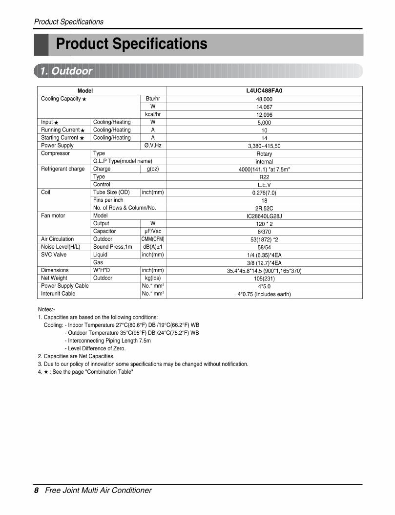
Product Specifications
Product Specifications
1. Outdoor
ModelCooling Capacity Btu/hr
Wkcal/hr
Input Cooling/Heating WRunning Current Cooling/Heating AStarting Current Cooling/Heating APower Supply Ø,V,HzCompressor Type
O.L.P Type(model name)Refrigerant charge Charge g(oz)
TypeControl
Coil Tube Size (OD) inch(mm)Fins per inchNo. of Rows & Column/No.
Fan motor ModelOutput WCapacitor µF/Vac
Air Circulation Outdoor CMM(CFM)Noise Level(H/L) Sound Press,1m dB(A)±1SVC Valve Liquid inch(mm)
GasDimensions W*H*D inch(mm)Net Weight Outdoor kg(lbs)Power Supply Cable No.* mm2
Interunit Cable No.* mm2
48,00014,06712,0965,000
1014
3,380~415,50Rotaryinternal
4000(141.1) "at 7.5m"R22
L.E.V0.276(7.0)
182R,52C
IC28640LG28J120 * 26/370
53(1872) *258/54
1/4 (6.35)*4EA3/8 (12.7)*4EA
35.4*45.8*14.5 (900*1,165*370)105(231)
4*5.04*0.75 (Includes earth)
L4UC488FA0
Notes:-1. Capacities are based on the following conditions:
Cooling: - Indoor Temperature 27°C(80.6°F) DB /19°C(66.2°F) WB- Outdoor Temperature 35°C(95°F) DB /24°C(75.2°F) WB- Interconnecting Piping Length 7.5m- Level Difference of Zero.
2. Capacities are Net Capacities.3. Due to our policy of innovation some specifications may be changed without notification.4. : See the page "Combination Table"

Service Manual 9
Product Specifications
2. Indoor
Indoor Unit Type
Model
Nominal Cooling Capacitykcal/hr(W)
Btu/hr
Air Circulation H/M/L CMM(CFM)
Setting temperature range(cool) °C
Fan motorOutput W
Capacitor µF/Vac
Noise LevelH/M/L dBA
(Sound Press,1.5m)
Temperature controller
Dehumidification Rate l/h
Dimensions (W*H*D) Body inch(mm)
Net Weight Body kg(lbs)
Liquid inch(mm)
Piping Connection Gas inch(mm)
Drain hose (ID Ø) mm
LMNC096LRL0 LMNC126LRL0 LMNC186LTL0 LMNC096DUR0 LMNC126DUR0 LMNC186D3R0
2267(2638) 3024(3517) 4536(5275) 2267(2638) 3024(3517) 4536(5275)
9,000 12,000 18,000 9,000 12,000 18,000
8.5(300) 9.0(318) 13(460) 8.5(300) 9.0(318) 13(460)
18~30 18~30 18~30 18~30 18~30 18~30
14.4 14.4 22 7.8 7.8 25.6
0.9/400 0.9/400 2.0/370 0.9/400 0.9/400 2/370
35/33/31 39/36/34 42/39/36 36/32/29 37/33/31 40/38/36
Thermistor Thermistor Thermistor Thermistor Thermistor Thermistor
1.4 1.8 2 1.2 1.5 2
35.4*11.2*6.1(900*285*156) 35.4*11.2*6.1(900*285*156) 42.9*12.4*6.8(1090*314*172) 40.6*11.4*6.0(1030*290*153) 40.6*11.4*6.0(1030*290*153) 46.1*24.4*6.81(1170*315*173)
8(17.6) 8(17.6) 12(26.5) 9.5(20.9) 9.5(20.9) 13(28.7)
1/4 (6.35) 1/4 (6.35) 1/4 (6.35) 1/4 (6.35) 1/4 (6.35) 1/4 (6.35)
3/8 (9.52) 1/2 (12.7) 1/2 (12.7) 3/8 (9.52) 1/2 (12.7) 1/2 (12.7)
20 20 20 20 20 20
Wall Mounted Art Cool
Indoor Unit Type
Model
Nominal Cooling Capacitykcal/hr(W)
Btu/hr
Air Circulation H/M/L CMM(CFM)
Setting temperature range(cool) °C
Fan motorOutput W
Capacitor µF/Vac
Noise LevelH/M/L dBA
(Sound Press,1.5m)
Temperature controller
Dehumidification Rate l/h
Dimensions (W*H*D) Body inch(mm)
Net Weight Body kg(lbs)
Liquid inch(mm)
Piping Connection Gas inch(mm)
Drain hose (ID Ø) mm
LMNC246PRC2 LMNC286PRC2 LMNC346PRC2
6048(7034) 7056(8260) 8568(9964)
24,000 28,000 34,000
18.5/14/12/8(653/494/424) 20/16.5/13/8(706/583/459/283) 21/18/15.5/6(742/636/547/212)
18~30 18~30 18~30
47.4 102 82.8
2.5/440 4/450 2.5/440
46/45/44 48/47/46 50/49/48
Thermistor Thermistor Thermistor
2.1 3.2 3.8
22.4*71.7*12.5(570*1,820*317) 22.4*71.7*12.5(570*1,820*317) 22.4*71.7*12.5(570*1,820*317)
36(79) 36(79) 36(79)
1/4 (6.35) 1/4 (6.35) 1/4 (6.35)
5/8 (15.88) 5/8 (15.88) 5/8 (15.88)
16 16 16
PAC
Notes:-1. Capacities are based on the following conditions:
Cooling: - Indoor Temperature 27°C(80.6°F) DB /19°C(66.2°F) WB- Outdoor Temperature 35°C(95°F) DB /24°C(75.2°F) WB- Interconnecting Piping Length 7.5m- Level Difference of Zero.
2. Capacities are Net Capacities.3. Due to our policy of innovation some specifications may be changed without notification.4. : See the page "Combination Table"

10 Free Joint Multi Air Conditioner
Combination Table
Combination Table
L4UC488FA0
9 9 10 10 2200 4.112 12 12 12 2300 4.2
1 UNIT18 18 18 18 2400 4.424 24 24 24 2500 4.528 28 28 28 4600 8.334 34 34 34 4600 8.49 9 18 9 9 18 2400 4.59 12 21 9 12 21 2500 4.612 12 24 12 12 24 2600 4.79 18 27 9 18 27 4500 8.512 18 30 12 18 30 4700 8.69 24 33 9 24 33 4700 8.612 24 36 12 24 36 4800 8.618 18 36 18 18 36 4800 8.8
2 UNIT 9 28 37 9 28 37 4800 8.612 28 40 12 28 40 4900 8.718 24 42 18 24 42 4900 8.99 34 43 9 34 43 4900 8.612 34 46 12 34 46 4900 8.718 28 46 18 28 46 5000 8.924 24 48 24 24 48 5000 8.918 34 52 18 34 52 5100 8.924 28 52 24 28 52 5100 9.09 9 9 27 9 9 9 27 4600 8.69 9 12 30 9 9 12 30 4700 8.79 12 12 33 9 12 12 33 4800 8.89 9 18 36 9 9 18 36 4800 8.912 12 12 36 12 12 12 36 4900 8.99 12 18 39 9 12 18 39 4900 9.09 9 24 42 9 9 24 42 4900 9.012 12 18 42 12 12 18 42 5000 9.19 12 24 45 9 12 24 45 5000 9.1
3 UNIT 9 18 18 45 9 18 18 45 5000 9.29 9 28 46 9 9 28 46 5000 9.112 12 24 48 12 12 24 48 5100 9.112 18 18 48 12 18 18 48 5200 9.29 12 28 49 9 12 28 49 5100 9.19 18 24 51 9 18 24 51 5100 9.39 9 34 52 9 9 34 52 5100 9.212 12 28 52 12 12 28 52 5200 9.312 18 24 54 12 18 24 54 5200 9.418 18 18 54 18 18 18 54 5200 9.59 9 9 9 36 9 9 9 9 36 4800 9.09 9 9 12 39 9 9 9 12 39 4900 9.19 9 12 12 42 9 9 12 12 42 5000 9.29 9 9 18 45 9 9 9 18 45 5000 9.39 12 12 12 45 9 12 12 12 45 5100 9.3
4 UNIT 9 9 12 18 48 9 9 12 18 48 5100 9.412 12 12 12 48 12 12 12 12 48 5100 9.29 9 9 24 51 9 9 9 24 51 5100 9.49 12 12 18 51 9 12 12 18 51 5200 9.59 9 12 24 54 9 9 12 24 54 5200 9.512 12 12 18 54 12 12 12 18 54 5300 9.6
Combimation of Indoor unit(k Btu/h)Cooling
Each Capacity Input(W)
Current(A)Unit-A Unit-B Unit-C Unit-D Total Unit-A Unit-B Unit-C Unit-D Total
Operation
Unit

Service Manual 11
Dimensions
Dimensions
1. Indoor Unit
• RAC
Installation plate
D
H
W
Installation plate
Pipe See NoteDrain Hose
D
H
W
• DCR
Capacity W H DSQ Ch. 7K/9K 824 260 156SR Ch. 12K 900 285 156ST Ch. 18K/24K 1080 314 182
Model W H DLMN096DUR0
1030 290 153LMNC126DUR0LMNC186D3R0 1170 315 173

Dimensions
12 Free Joint Multi Air Conditioner
• PAC
No. Items1 Control Display2 Air outlet vent3 Air inlet vent4 Sliding Clean Door
4
1
3
2
1,82
0
570 311

Service Manual 13
Dimensions
L6L7 L8L9
L4
H
L5
W
D L1
L3
L2
L10
L11L
11L1
1L1
1L1
1L1
1L1
1
Gas side3-way valve
Liquid side2-way valve
W mm 870
H mm 1038
D mm 320
L1 mm 360
L2 mm 340
L3 mm 25
L4 mm 1035
L5 mm 25
L6 mm 546
L7 mm 160
L8 mm 160
L9 mm 44
L10 mm 64.5
L11 mm 50
L4UC488FA0MODEL
DIM
2. Outdoor UnitL4UC488FA0

14 Free Joint Multi Air Conditioner
Refrigeration Cycle Diagram
Refrigeration Cycle Diagram
L4UC488FA0
Indoor Side Outdoor Side
B A
COMP BCOMP AA
ccum
.CD
ex)
Solenoid Valve
L.E.V
3-Way Valve
2-Way Valve
Capillary
Service Manual 15
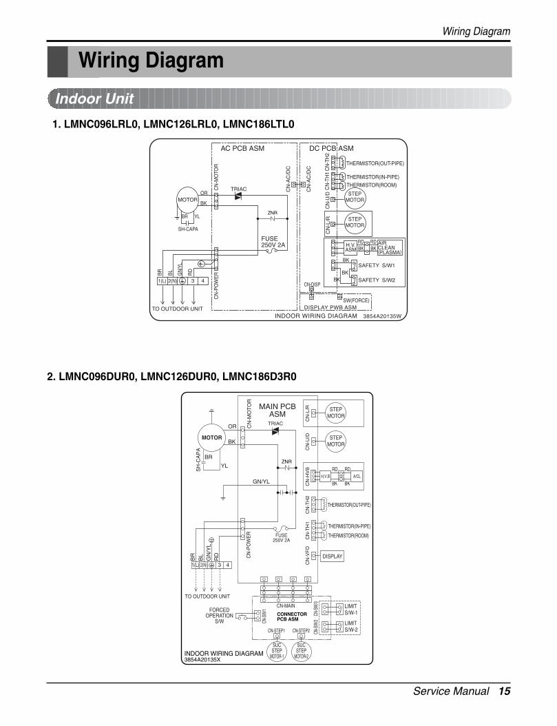
Wiring Diagram
Wiring Diagram
Indoor Unit
1. LMNC096LRL0, LMNC126LRL0, LMNC186LTL0
2. LMNC096DUR0, LMNC126DUR0, LMNC186D3R0
3854A20135W
CN
-TH
1
THERMISTOR(OUT-PIPE)
THERMISTOR(IN-PIPE)
THERMISTOR(ROOM)
CN
-TH
2C
N-U
/D
CN
-MO
TOR
CN
-PO
WE
R
AC PCB ASM DC PCB ASM
FUSE250V 2A
ZNR

Wiring Diagram
16 Free Joint Multi Air Conditioner
3. LMNC246PRC2,LMNC286PRC2,LMNC366PRC2

Service Manual 17
Wiring Diagram
Outdoor Unit1. L4UC488FA0

18 Free Joint Multi Air Conditioner
Electronic Control Device
Electronic Control Device
Indoor Unit
LMNC096LRL0, LMNC126LRL0, LMNC186LTL0
• MAIN P.C.B AC ASM

Service Manual 19
Electronic Control Device
LMNC096DUR0, LMNC126DUR0, LMNC186D3R0
• MAIN PCB ASM - TOP VIEW
• MAIN PCB ASM - BOTTOM VIEW
C06J
EARTH
FUSE
IC03D
R01J
CN_M
OT
OR
IC01K IC02K
IC01J
R02JR0
3J TR01J
JP31
NF02J
R05K
D01K
D02K
ZN
R02J
CN_P
OW
ER
JP28
JP29
C03J
C04J
JP33 CN_L/R(BL)
C06D
CN_U/D(WH)
Q01C
Q01V
BD01D
D02D
+
~
C05D
D05D
~
-
IC01D
IC02DZ
D02D
JP38
JP35
SD01D
C01J
NF01J
ZNR01J
NTCJP30
C05J
250V/T2A
7
1
CN_CC
BZ01E
C01E
C01D
JP4
0
JP39
4
3
SMPS
JP34
D07D
L1
JP1
JP4
1
JP4
2
ASM
: 68
71A
1011
1
PCB
: 687
0A90
120C
IC1
JP19
C02A IC01A
JP50 JP53
JP4
9
OSC01B
JP52
JP51
JP12
JP56
JP54
JP55
CN_HVB(BL)
IC04D
C04D
C09D
JP4
4
CN_SUC(WH)
JP43
CN_TH1
JP4
5
JP58
JP4
8
JP46
CN_VFD(WH)JP11
CN_CON(BL)
JP47
CN_TH2
JP32
C06J
IC03D
C04J
CN
-MO
TO
R
R03
J
JP13 C01K R01KR04D JP6JP7
R02
KR
04K
Q01
KR
05K
IC02K IC01K
R04
J
JP31
IC01J
R03
K
D02
KD
01K
NF02J
ZNR02J
TR01J
CN
-PO
WE
R
R01J
JP28
JP29
C03
J
JP33
CN-U/D(WH)
JP12
CN
-CO
N(B
L)
C06D
Q01
C
JP9
JP2
C01
L
JP22
BC01D
R05
D
R02
J
D02
D
R06
D
C02
D
D05
D
R05
VJP
26
R02
DR
03D
R06
VJP
15
C05D
ZD
02D
IC02D
IC01D
JP36
JP24
JP21
JP37
Q02
V
R04
E
R08
DJP
17
JP18
JP38
C01D
SMPS
SD01D
JP35
ZNR01J
JP30
NF01J
C01J
NTC
C05J
EARTH
CN-CC
FUSE
250V/T2A
R23
G
R21
G
R22
G
R24
G
C10
DQ
03E
Q01
E
R01
ER
02E
JP25
Q02
ER
02L
R03
E
C01E
JP40
JP39
JP5 JP
27
JP34IC04M
L1
D07
D
JP1
30
JP49
JP10
JP8
R01
L
R01P
R07
D
JP41
Q01
V
IC1
JP42
JP23
JP14
C01AR01A
R02AJP50
IC01A
20
25
JP54
JP53
JP52
JP51
OR2H
L01X
L02X
R01
B 10
15
JP19
C01
X
C01
GR
01G
JP56
JP55
CN-HVB(BL)
R01
FR
02F
C07
D
C08D
C04D
C09D
MICOM
JP44
IC04
D
40
45
IC01M
JP43
IC02M
JP57
CN-SUC(WH)
C01
HC
04V
R06
H
JP45
1
50
55
JP58
R01
HR
02H
R03
V
R04
VR
05H
R21
H
R22
HR
23H
C03V
C02H
JP48
JP47
JP46
CN-VFD(WH)
C01
F
CN-TH1
JP4
OR
1HO
R3H
R02
GJP
3JP
16
C03
HR
03H
R04
H
CN-CH2
JP20JP32
CN-L/R(BL)

Electronic Control Device
20 Free Joint Multi Air Conditioner
LMNC246PRC2, LMNC286PRC2, LMNC366PRC2
• MAIN PCB ASM

Service Manual 21
Electronic Control Device
L4UC488FA0
• MAIN P.C.B ASM
Outdoor Unit
Display P.C.B ASM
SEJIN ELECTRON INC. SVM-GP1119AI P/N 3210018043
1
REV1
C13
C7
C8
C9
D1
Q1
Q2R9
R13
R2 R6
R7R8
R10
TP1
TP2
TP3TP4
R17
R18
R19
C14C15
C18
R4 R3
TP5
TP6
M42
M43 C19
C20
C21
R5
M45M44
Art Cool Deluxe TypeTOP VIEW
BOTTOM VIEW
TP1TP2
TP3TP4
TP7
TP8
All of M/S SW 1, 2, 3, 4 must be on 'M'

22 Free Joint Multi Air Conditioner
Schematic Diagram
Schematic Diagram
Indoor Unit
1. LMNC096LRL0, LMNC126LRL0, LMNC186LTL0

Service Manual 23
Schematic Diagram
2. LMNC096DUR0, LMNC126DUR0, LMNC186D3R0

Schematic Diagram
24 Free Joint Multi Air Conditioner
3. LMNC246PR30, LMNC286PR30, LMNC366PR30

Service Manual 25
Schematic Diagram
Outdoor Unit• L4UC488FA0

26 Free Joint Multi Air Conditioner
Functions
Functions
• Room temperature sensor. (THERMISTOR)
• Maintains the room temperature in accordance with the Setting Temp.
• Indoor fan is delayed for 5 sec at the starting.
• Restarting is inhibited for approx. 3 minutes.
• High, Med, Low, CHAOS, JET COOL
• Refer to 37 page signal receptor.
• Intermittent operation of fan at low speed.
• The fan is switched to low(Cooling), med(Heating) speed.• The unit will be stopped after 1, 2, 3, 4, 5, 6, 7 hours.
• The fan is switched to intermittent or irregular operation• The fan speed is automatically switched from high to low speed.
• The louver can be set at the desired position or swingup and down automatically.
Indoor Unit
Operation ON/OFF by Remote controller
Sensing the Room Temperature
Room temperature control
Starting Current Control
Time Delay Safety Control
Indoor Fan Speed Control
Operation indication Lamps (LED)
Soft Dry Operation Mode
• The function will be operated while in anyoperation mode with selecting the function.
• The function is to be stopped while it isoperating with selecting the function.
• Both the indoor and outdoor fan stops dur-
ing defrosting.
• The indoor fan stops until theevaporator pipe temperature will be reachedat 28°C.
Sleep Mode Auto Control
Natural Air Control by CHAOS Logic
Airflow Direction Control
Defrost(Deice) control (Heating)
Hot-start Control (Heating)
PLASMA

Service Manual 27
Functions
Remote Controller
JET COOL
Healthy Dehumidification Operation Mode.( )
Operation Mode Selection
(Cooling model only)
Cooling Operation Mode.( ) Auto Operation Mode.( )
Sleep Operation
Fan Operation Mode
Room, Temperature Display
Setting the Time or Timer
Airflow Direction Control
Operation ON/OFF
Temperature SettingTEMPERATURE LOWHIGH
Timer SelectionON OFF
Timer SettingSET
Timer CancelCANCEL
Reset
Fan Speed Selection
(Low) (Med) (High) (CHAOS)
: (High: 39°C LOW : 11°C)
Down to 18°C
Up to 30°CCooling
: OFF, ON, OFF ON
: Cancel Sleep Mode, Timer ON or Timer OFF
: 1, 2, 3, 4, 5, 6, 7, Off Timer
: Fan Operates without cooling or heating.

28 Free Joint Multi Air Conditioner
Functions
Healthy Dehumidification Operation Mode.( )
Art Cool Deluxe Type Remote Controller
Operation ON/OFF
Reset
Operation Mode Selection
Temperature Setting
Timer Selection
Timer Setting
JET COOL
Timer Cancel
Sleep Operation
Airflow Direction Control
(Cooling model only)
TEMPERATURE LOW HIGH
Cooling Operation Mode.( ) Auto Operation Mode.( )
Air Circulation
Horizontal Airflow Direction Control Button(Optional)
Room, Temperature Checking
Setting the Time or Timer
Fan Speed Selection
(Low) (Med) (High)
ON OFF
CANCEL
SET
2nd F
: (High:39°C Low:11°C)
: OFF, ON, OFF ON
: Cancel Sleep Mode, Timer ON or Timer OFF
: 1, 2, 3, 4, 5, 6, 7, Off Timer
: Fan Operates without cooling or heating.
Cooling Down to 18°CUp to 30°C
Heating Down to 16°CUp to 30°C
Service Manual 29
Functions
ON OFF
SET CANCEL
910
12
11
6
13
78
14
5
12
4
3
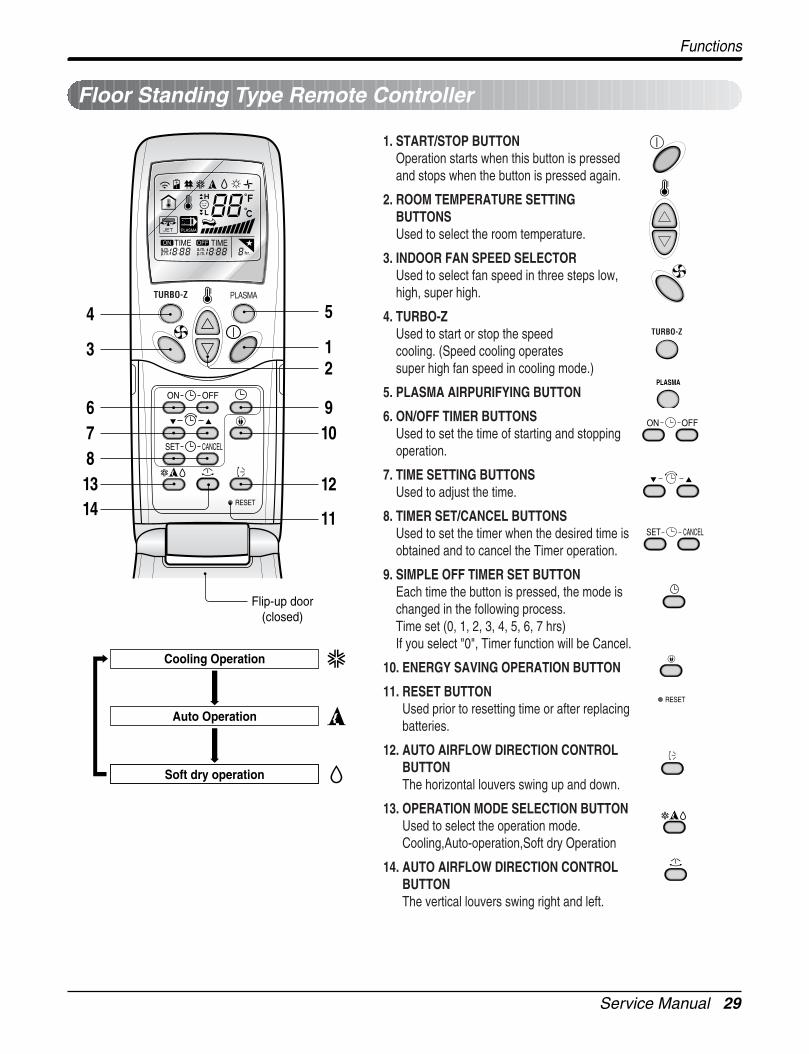
Cooling Operation
Auto Operation
Soft dry operation
Flip-up door(closed)
1. START/STOP BUTTONOperation starts when this button is pressedand stops when the button is pressed again.
2. ROOM TEMPERATURE SETTINGBUTTONSUsed to select the room temperature.
3. INDOOR FAN SPEED SELECTORUsed to select fan speed in three steps low,high, super high.
4. TURBO-ZUsed to start or stop the speed cooling. (Speed cooling operates super high fan speed in cooling mode.)
5. PLASMA AIRPURIFYING BUTTON
6. ON/OFF TIMER BUTTONSUsed to set the time of starting and stoppingoperation.
7. TIME SETTING BUTTONSUsed to adjust the time.
8. TIMER SET/CANCEL BUTTONSUsed to set the timer when the desired time isobtained and to cancel the Timer operation.
9. SIMPLE OFF TIMER SET BUTTONEach time the button is pressed, the mode ischanged in the following process.Time set (0, 1, 2, 3, 4, 5, 6, 7 hrs)If you select "0", Timer function will be Cancel.
10. ENERGY SAVING OPERATION BUTTON
11. RESET BUTTONUsed prior to resetting time or after replacingbatteries.
12. AUTO AIRFLOW DIRECTION CONTROLBUTTONThe horizontal louvers swing up and down.
13. OPERATION MODE SELECTION BUTTONUsed to select the operation mode.Cooling,Auto-operation,Soft dry Operation
14. AUTO AIRFLOW DIRECTION CONTROLBUTTONThe vertical louvers swing right and left.
Floor Standing Type Remote Controller

30 Free Joint Multi Air Conditioner
Operation Details
Operation Details
Main Unit Function1) C/O Model
Operation Indicator• On while in appliance operation, off while in appliance pause• Flashing while in disconnection or short in Thermistor (3 sec off / 0.5 sec on)
Sleep Timer Indicator• On while in sleep timer mode, off when sleep timer cancel or appliance operation pause
Timer Indicator• On while in timer mode (on/off), off when timer mode is completed or canceled.
Comp. Running Incidator• While in appliance operation, on while in outdoor unit compressor running, off while in compressor off
Cooling Mode Operation• When the intake air temperature reaches 0.5°C below the setting temp, the compressor and the outdoor fan
stop.• When it reaches 0.5°C above the setting temp, they start to operate again.
Compressor ON Temp Setting Temp+0.5°CCompressor OFF Temp Setting Temp-0.5°C
• While in compressor running, operating with the airflow speed set by the remote control. While in compressornot running, operating with the low airflow speed regardless of the setting.
Healthy Dehumidification Mode• When the dehumidification operation input by the remote control is received, the intake air temperature is
detected and the setting temp is automatically set according to the intake air temperature.26°C ≤ Intake Air Temp 25°C24°C ≤ Intake Intake Air Temp<26°C Intake Air Temp-1°C18°C ≤ Intake Intake Air Temp<24°C Intake Air Temp-0.5°CIntake Air Temp<18°C 18°C
• While in compressor off, the indoor fan repeats low airflow speed and pause.• While the intake air temp is between compressor on temp. and compressor off temp., 10-min dehumidification
operation and 4-min compressor off repeat.Compressor ON Temp. Setting Temp+0.5°CCompressor OFF Temp. Setting Temp-0.5°C• In 10-min dehumidification operation, the indoor fan operates with the low airflow speed.

Service Manual 31
Operation Details
Fuzzy Operation (C/O Model)• According to the temperature set by Fuzzy rule, when the intake air temp is 0.5°C or more below the setting
temp, the compressor is turned off. When 0.5°C or more above the setting temp, the compressor is turned on.Compressor ON Temp Setting Temp + 0.5°CCompressor OFF Temp Setting Temp + 0.5°C
• At the beginning of Fuzzy mode operation, the setting temperature is automatically selected according to theintake air temp at that time.26°C ≤ Intake Air Temp 25°C24°C ≤ Intake Air Temp < 26°C Intake Air Temp + 1°C22°C ≤ Intake Air Temp < 24°C Intake Air Temp + 0.5°C18°C ≤ Intake Air Temp < 22°C Intake Air TempIntake Air Temp<18°C 18°C
• When the Fuzzy key (Temperature Control key) is input after the initial setting temperature is selected, theFuzzy key value and the intake air temperature at that time are compared to select the setting temperatureautomatically according to the Fuzzy rule.
• While in Fuzzy operation, the airflow speed of the indoor fan is automatically selected according to thetemperature.
3. Display Ass'y
32 Free Joint Multi Air Conditioner
Operation Details
Off-Timer Operation• When the set time is reached after the time is input by the remote control, the appliance stops operating.• The timer LED is on when the off-timer is input. It is off when the time set by the timer is reached.• If the appliance is on pause at the time set by the timer, the pause continues.
Off-Timer ↔ On-Timer Operation• When the set time is reached after the on/off time is input by the remote control, the on/off-timer operation is
carried out according to the set time.
Sleep Timer Operation• When the sleep time is reached after <1,2,3,4,5,6,7,0(cancel) hr> is input by the remote control while in appli-
ance operation, the operation of the appliance stops.• While the appliance is on pause, the sleep timer mode cannot be input.• While in cooling mode operation, 30 min later since the start of the sleep timer, the setting temperature
increases by 1°C. After another 30 min elapse, it increases by 1°C again.• When the sleep timer mode is input while in cooling cycle mode, the airflow speed of the indoor fan is set to
the low.• When the sleep timer mode is input while in heating cycle mode, the airflow speed of the indoor fan is set to
the medium.
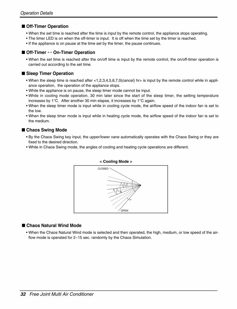
Chaos Swing Mode• By the Chaos Swing key input, the upper/lower vane automatically operates with the Chaos Swing or they are
fixed to the desired direction.• While in Chaos Swing mode, the angles of cooling and heating cycle operations are different.
Chaos Natural Wind Mode• When the Chaos Natural Wind mode is selected and then operated, the high, medium, or low speed of the air-
flow mode is operated for 2~15 sec. randomly by the Chaos Simulation.
CLOSED
OPEN
< Cooling Mode >
7°

Service Manual 33
Operation Details
Jet Cool Mode Operation (C/O Model)• If the Jet Cool key is input at any operation mode while in appliance operation, the Jet Cool mode operates.• In the Jet Cool mode, the indoor fan is operated at super-high speed for 30 min at cooling mode operation.• In the Jet Cool mode operation, the room temperature is controlled to the setting temperature, 18°C• When the sleep timer mode is input while in the Jet Cool mode operation, the Jet Cool mode has the priority.• When the Jet Cool key is input, the upper/lower vanes are reset to those of the initial cooling mode and then
operated in order that the air outflow could reach further.
Forced Operation• Operation procedures when the remote control can't be used.• The operation will be started if the power button is pressed.• If you want to stop operation, re-press the button.
• While in forced operation, the key input by the remote control has no effect and the buzzer sounds 10 times toindicate the forced operation.
Test operation• During the TEST OPERATION, the unit operates in cooling mode at high speed fan, regardless of room tem-
perature and resets in 18±1 minutes.• During test operation, if remote controller signal is received, the unit operates as remote controller sets.
If you want to use this operation, open the front panel upward and Press the power button let it be pressed forabout 3 seconds.
• If you want to stop the operation, re-press the button.
Auto restart• In case the power comes on again after a power failure, Auto Restarting Operation is the function to operate
procedures automatically to the previous operating conditions.
Air Cleaner Operation• When an air cleaner function is selected during Air Conditioner operation
- Plasma air cleaner function will be operated while in any operation mode with selecting the function.- The function is to be stopped while it is operating with selecting the function.
• When an air cleaner function is selected during operation off- The function will be only operated.
• When inlet grille of air conditioner is opened during plasma operation, High Voltage Generator(H.V.B) is to bestopped. When inlet grille of air conditioner is closed during plasma operation, High Voltage Generator(H.V.B)will be operated again.
Cooling Model
Operating mode Cooling
Indoor FAN Speed High
Setting Temperature 22°C
34 Free Joint Multi Air Conditioner
Operation Details
Remote Control Operation Mode• When the remote control is selected by the slide switch on the main unit, the appliance operates according to
the input by the remote control.
Protection of the evaporator pipe from frosting• If the indoor pipe temp is below 0°C in 7 min. after the compressor operates without any pause while in cool-
ing cycle operation mode, the compressor and the outdoor fan are turned off in order to protect the indoorevaporator pipe from frosting.
• When the indoor pipe temp is 7°C or higher after 3 min. pause of the compressor, the compressor and theoutdoor fan is turned on according to the condition of the room temperature.
Buzzer Sounding Operation• When the appliance-operation key is input by the remote control, the short "beep-beep-" sounds.• When the appliance-pause key is input by the remote control, the long "beep—" sounds.• When a key is input by the remote control while the slide switch on the main unit of the appliance is on the
forced operation position, the error sound "beep-beep-beep-beep-beep-" is made 10 times to indicate that theremote control signal cannot be received.

Service Manual 35
2-way, 3-way Valve
2-way, 3-way Valve
3.
2.
1.
4.
5.
Flare nut
To piping connection
Open positionClosed position
Flare nut
Valve cap
To piping connection
Open positionClosed position
Hexagonal wrench(4mm)
To outdoor unit
Pin
Service port
Service port cap
To outdoor unit
2-way Valve (Liquid Side) 3-way Valve (Gas Side)
Works
Shipping
Pumping down(Transfering)
Closed(clockwise)
Open(counter-clockwise)
Open(connected manifold gauge)
Evacuation(Servicing)
Open OpenOpen
(with charging cylinder)
Gas charging(Servicing)
Open OpenOpen
(with charging cylinder)
Pressure check(Servicing)
Open OpenOpen
(with charging cylinder)
Gas releasing(Servicing)
Open OpenOpen
(with charging cylinder)
Closed(with valve cap)
Closed(with valve cap)
Closed(with valve cap)
Shaft position Shaft position Service port

36 Free Joint Multi Air Conditioner
2-way, 3-way Valve
• Procedure1. Confirm that both the gas side and liquid side
valves are set to the open position.- Remove the valve stem caps and confirm that
the valve stems are in the raised position.
- Be sure to use a hexagonal wrench to operatethe valve stems.
2. Operate the unit for 10 to 15 minutes.
3. Stop operation and wait for 3 minutes, then con-nect the manifold gauge to the service port ofthe gas side valve.- Connect the hose of the gauge with the push
pin to the service port.
4. Air purging of the charge hose.- Open the Low-handle valve on the gauge
slightly to air purge from the hose.
5. Set the liquid side valve to the closed position.
6. Operate the air conditioner at the cooling cycleand stop it when the gauge indicates 1kg/cm2g.
7. Immediately set the gas side valve to the closedposition.- Do this quickly so that the gauge ends up indi-
cating 1kg/ g.
8. Disconnect the charge set, and mount the liquidside and gas side valve caps and the serviceport nut.- Use torque wrench to tighten the service port
nut to a torque of 1.8kg.m.(4.2kg*m/5.5kg*m)
- Be sure to check for gas leakage.
Indoor unit
Outdoor unit
Liquid side
Close
Gas side
2-Wayvalve
Open3-Wayvalve
manifold gauge
Indoor unit Liquid side
Close
Gas side
2-Wayvalve
Open3-Wayvalve
Hi- handle(CLOSE)
Low-handle(CLOSE)
(1) Pumping down

Service Manual 37
2-way, 3-way Valve
(2) Evacuation(All amount of refrigerant leaked)
• Procedure1. Confirm that both the liguid side valve and gas
side valve are set to the opened position.
2. Connect the vaccum pump to the center hose ofthe manifold gauge.
3. Connect the service port of the gas side valve tothe low side of the gauge.
4. Connect power supply to outdoor unit.5. Evacuation for approximately one hour.
- Confirm that the gauge needle has movedtoward-76 cmHg (vacuum of 4 mmHg or less).
6. Close the Low handle of the gauge turn off thevacuum pump, and confirm that the gauge nee-dle does not move(approximately 5 minutesafter turning off the vacuum pump).
7. Disconnect the charge hose from the vacuumpump.- Vacuum pump oil.
If the vacuum pump oil becomes dirty or deplet-ed,replenish as needed.
8. Mount the valve caps and the service port caps.
Indoor unit
Outdoor unit
Liquid side
Open
Gas side
2-Wayvalve
Open3-Wayvalve
manifold gauge
Indoor unit Liquid side
Open
Gas side
2-Wayvalve
Open3-Wayvalve
Vacuum pump
Hi- handle(OPEN)
Low-handle(OPEN)

38 Free Joint Multi Air Conditioner
2-way, 3-way Valve
(3) Gas Charging(After Evacuation)
• Procedure1. Connect the gauge to the charging cylinder.
- Connect the charge hose which you disconnect-ed from the vacuum pump to the valve at thebottom of the cylinder.
- If you are using a gas cylinder, also use a scaleand reverse the cylinder so that the system canbe charged with liquid.
2. Purge the air from the charge hose.- Open the valve at the bottom of the cylinder and
press the check valve on the charge set to purgethe air. (Be careful of the liquid refrigerant). Theprocedure is the same if using a gas cylinder.
3. Open the low handle on the gauge and chargethe system with liquid refrigerant.- If the system can not be charged with the speci-
fied amount of refrigerant, it can be chargedwith a little at a time (approximately 150g eachtime) while operating the air conditioner in thecooling cycle; however, one time is not suffi-cient, wait approximately 1 minute and thenrepeat the procedure(pumping down-pin).
4. Immediately disconnect the charge hose fromthe gas side valve's service port.
- Stopping partway will allow the gas to be dis-charged.
- If the system has been charged with liquidrefrigerant while operating the air conditionerturn off the air conditioner before disconnectingthe hose.
5. Mount the valve stem nuts and the service portnut.- Use torque wrench to tighten the service port
nut to a torque of 1.8 kg.m.(4.2kg.m/5.5kg.m.)- Be sure to check for gas leakage.
manifold gaugeChargingcylinder
Hi- handle(OPEN)
Low-handle(OPEN)Check valve
Indoor unit
Outdoor unit
Liquid side
Open
Gas side
2-Wayvalve
Open3-Wayvalve
Indoor unit Liquid side
Open
Gas side
2-Wayvalve
Open3-Wayvalve
This is different from previous procedures.Because you are charging with liquid refrigerantfrom the gas side, absolutely do not attempt tocharge with larger amounts of liquid refrigerantwhile operating the air conditioner.

Service Manual 39
Cycle Troubleshooting Guide
Trouble analysis1. Check temperature difference between intake and discharge air, and operating current.
All amount of refrigerant leaked out.Check refrigeration cycle.
Refrigerant leakageClog of refrigeration cycleDefective compressor
Excessive amount of refrigerant
Normal
Notice:Temperature difference between intake and discharge air depends on room air humidity. When the room airhumidity is relatively higher, temperature difference is smaller. When the room air humidity is relatively lowertemperature difference is larger.
2. Check temperature and pressure of refrigeration cycle.
Notice:1. The suction pressure is usually 8~12 kg/cm2G at normal condition.2. The temperature can be measured by attaching the thermometer to the low pressure tubing and wrap it with
putty.
Temp. difference : approx. 0°CCurrent : less than 80% of
rated current
Temp. difference : approx. 8°CCurrent : less than 80% of
rated current
Temp. difference : less than 8°CCurrent : near the rated
current
Temp. difference : over 8°C
Temp. Difference
Operating Current
Suction pressure Temperature(Compared with (Compared with Cause of Trouble Description
the normal value) the normal value)
High Defective compressor Current is low.
Normal Excessive amount of High pressure does not quicklyrefrigerant rise at the beginning of operation.
Insufficient amount ofLower Higher refrigerant(Leakage) Current is low.
Clogging
Higher
Cycle Troubleshooting Guide

40 Free Joint Multi Air Conditioner
Cycle Troubleshooting Guide
1) Comp basic step.
Free joint outdoor unit has two compressor (MPS: Multi power system)
If overload Max. capacity, display error code in indoor unit.
2) Capacity Vs Step
cf) Max. Capacity : 54k
Step Step 0 Step 1 Step 2 Step 3 Step 4
Operating Comp. Off 1 1 2 2
By-pass Off On Off On Off
Q2 = 0 Q2 ≤ 12k Q2 ≤ 24k Q2 ≤ 36k 36k < Qs
Step Step 0 Step 1 Step 2 Step 3 Step 4

Service Manual 41
Electronic Parts Troubleshooting Guide
Electronic Parts Troubleshooting Guide
1. The Outdoor Unit does not operate at all
Does the Operating LED of indoor unit blinkwhen Operation’s ON?
Refer to the self-diagnosis function.
NO
NO
Is the Connection between CN-Power of indoorunit and terminal block?
Check the connecting state of connector
NO
YES
Is the voltage of CN-POWER in outdoorPCB Ass’y about AC220V / 240V?
Check the main power
NO
YES
Check the Fuse of outdoor PCB Ass’y.Chek the connecting state of wires
Replace the PCB Ass’y.
NO
Is the connection of cable between indoor andoutdoor unit ringht?
Indoor Outdoor
1(L)(Brown) 1(L)(Brown)
2(N)(Blue) 2(N)(Blue)
(Green/YL) (Green/YL)
3(Red) 3(Red)
NO
YES
* TPS units start at three minutes after main power turning on.

42 Free Joint Multi Air Conditioner
Electronic Parts Troubleshooting Guide
2. The product is not operate with the remote controller.
Turn on Main Power
While the compressor has been stopped, the compressor does notoperate owing to the delaying function for 3 minutes after stopped.
Caused by other parts except the remote controllerCaused by the remote controller
When the mark( ) is displayed in LCD screen, replacebattery.
Check the contact of CN-DISP1 connector.
When the compressor stopped Indoor Fan is driven by a low speed.At this point the wind speed is not controlled by the remote controller.(When operated in the Sleeping Mode, the wind speed is set to thelow speed by force.)
Check DISP PWB Ass'y- Voltage between CN DISP1 - : DC +5V
When the detect switch(double key) inside the remotecontroller door is fault, it is impossible to operatetemperature regulating( / ) and wind speed selecting.
Replace remote controller Check point
• Check the connecting circuit between PIN -R01L(1K) - C01L(680PF) - MICOM PIN
• Check Receiver Ass'y

Service Manual 43
Electronic Parts Troubleshooting Guide
3. When cooling does not operate
Turn on Main Power
Operate "Cooling Mode( )" by setting the desired temperature of theremote controller is less than one of the indoor temperature by 1°C at least.
When in Air Circulation Mode, Compressor/Outdoor Fan is stopped.
Check the sensor for indoor temperature is attached as close as to beeffected by the temperature of Heat Exchanger(EVA).
When the sensor circuit for indoor temperature and connector are in badconnection or are not engaged, Compressor/Outdoor Fan is stopped.
• Check the indoor temperature sensor is disconnected or not(About 10kΩ / at 25°C).
Check Relay(RY - COMP) for driving compressor.
• When the power(About AC220V/240V) is applied to the connecting wireterminal support transferred to compressor, PWB Ass'y is normal.
• Check the circuit related to the relay.
Check point COMP ON COMP OFF
Below DC 1VAbout DC12V(app)
Between two pin of DCpart in relay for COMP

44 Free Joint Multi Air Conditioner
Electronic Parts Troubleshooting Guide
4. When indoor Fan does not operate
Check the SSR high speed operation by remote control.(The Indoor Fan Motor is connected)
Turn off Main power
Check the connection of CN-FAN or CN-MOTOR
Check the Fan Motor
Check the Fuse(AC250V/T2A)
Turn ON Main Power
Check the related circuit of indoor Fan Motor.
• The pin of Micom, and the part for driving SSR• Check the pattern• Check the SSR
- SSR Open: Indoor Fan Motor never operate- SSR short: Indoor Fan Motor always operates in case of ON or OFF.
The voltage of PIN NO 1(blue) and 3(yellow) of CN-FAN or CN-MOTOR.
About AC 160V over About AC 50V over
SSR is not damaged SSR Check

Service Manual 45
Electronic Parts Troubleshooting Guide
5. When Vertical Louver does not operate
• Confirm that the Vertical Louver is normally geared with the shaft ofStepping Motor.
• If the regular torque is detected when rotating the Vertical Louver withhands Normal
• Check the connecting condition of CN-U/D Connector• Check the soldering condition(on PWB) of CN-U/D Connector
If there are no problems after above checks
• Confirm the assembly conditions that are catching and interfering partsin the rotation radial of the Vertical Louver
Check the operating circuit of the Vertical Louver
• Confirm that there is DC +12V between pin (RED) of CN-U/D andGND.

46 Multi type Air Conditioner
Error Indicator
• The function is to self-diagnoisis airconditioner and express the troubles identifically if there is any trouble.• Error mark is ON/OFF for the operation LED of evaporator body in the same manner as the following table.• If more than two troubles occur simultaneously, primarily the highest trouble fo error code is expressed.• After error occurrence, if error is released, error LED is also released simultaneously.• To operate again on the occurrence of error code, be sure to turn off the power and then turn on.• Having or not of error code is different from Model.
Troubleshooting Guide
Self-diagnosis Function
Indoor Error
Error code DescriptionMPS
VariableLED 1(Red)
LED 2(Green)
IndoorStatus
00 No Error ON
01 Indoor Room themistor error 1time OFF
02 Indoor in-piping sensor error 2times OFF
03 Remote controller error 3times OFF
04 Drain Pump error 4times OFF
05 Communcation error between in and out 5times OFF
06 Indoor Out-Piping sensor error 6times OFF
07 Differnt mode operation 7times OFF
Outdoor Error
Error Code DescriptionMPS
VariableLED 1(Red)
LED 2(Green)
IndoorStatus
21 DC Peak (IPM Fault) 2times 1time OFF
22 CT 2(Max CT) 2times 2times OFF
23 DC Link Low Volt. 2times 3times OFF
24 L_P/Heater Sink 2times 4times OFF
25 Low voltage / Over voltage 2times 5times OFF
26 DC Comp Position Error 2times 6times OFF
27 PSC Fault Error 2times 7times OFF
28 DC Link High Volt 2times 8times OFF
32 D-Pipe High (INV) 3times 2times OFF
33 D-Pipe High (Normal) 3times 3times OFF
40 CT Sensor (Open/Short) 4times O OFF
41 INV. D-PipeTh Error(Open/Short) 4times 1time OFF
44 Outdoor air Th Error(Open/Short) 4times 4times OFF
45 Cond. Pipe Th Error(Open/Short) 4times 5times OFF
46 Suction Pipe Error(Open/Short) 4times 6times OFF
47 Const D-pipe Th Error(Open/Short) 4times 7times OFF
51 Capacity over 5times 1time OFF
54 Riversed phase 5times 3times OFF
60 EEPROM Check Sum Error 6times O OFF
61 Cond. Pipe High 6times 1time OFF
62 Heatsink High 6times 2times OFF
63 Cond. Pipe Low 6times 3times OFF
65 Heatsoml Th error (Open/Short) 6times 5times OFF

Service Manual 47
Troubleshooting Guide
General Information
Error Indicator (Indoor)
• The function is to self-diagnosis air conditioner and express the troubles if there is any trouble.• Error mark is displayed on display window of indoor units and wired-remote controller, and LED of outdoor unit
control board.• If more than two troubles occur simultaneously, lower number of error code is first displayed.• After error occurs, if error is released, error LED is also released simultaneously.
Indoor Error
1 digit 10 digit
Case of errorContentsErrorcode
Open / ShortOutlet pipe sensor06
Different operation modeDifferent operation mode07
Communication Poorly
Float switch Open
Communication Poorly
Open / Short
Open / ShortAir sensor (open/short)01
Inlet pipe sensor02
Communication(Indoor ↔ Wired R/Control)03
Drain pump/ Float switch04
Communication(Indoor ↔ Outdoor)05
Off
Off
Off
Off
Off
Off
Off
Indoor
Status
48 Multi type Air Conditioner
Troubleshooting Guide
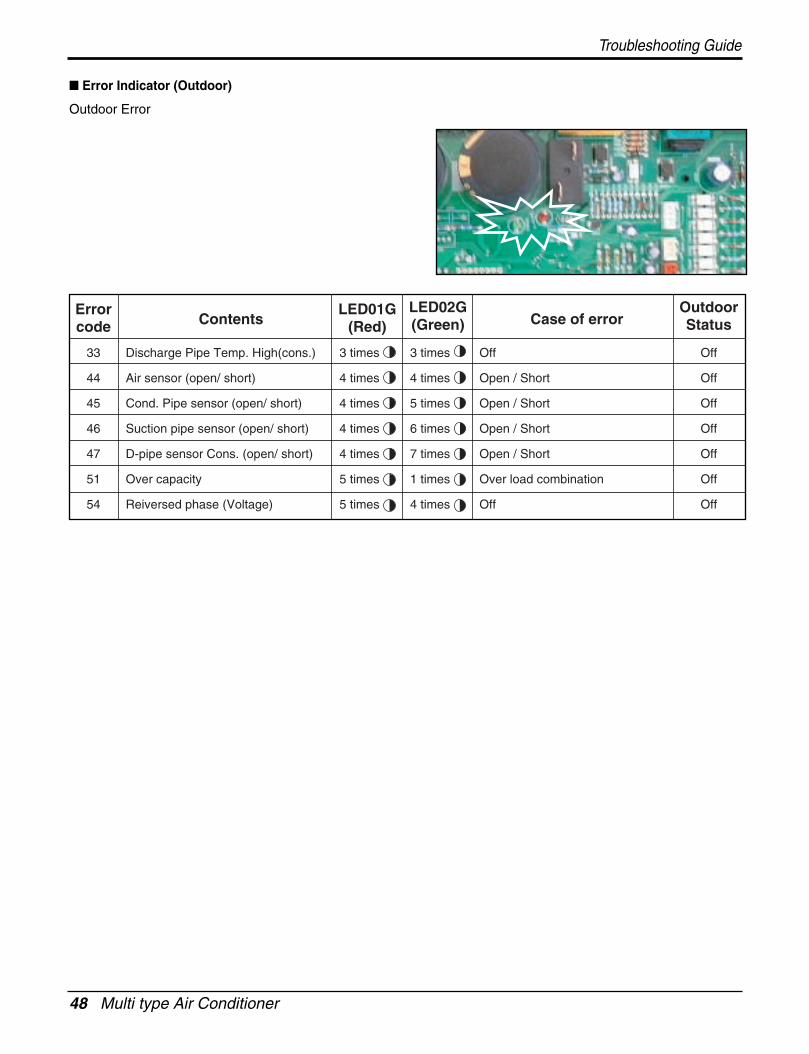
Error Indicator (Outdoor)
Outdoor Error
Case of errorLED02G(Green)
LED01G(Red)Contents
Errorcode
Off
Open / Short
Open / Short
Open / Short
Open / Short
Over load combination
Off
Discharge Pipe Temp. High(cons.)
Air sensor (open/ short)
Cond. Pipe sensor (open/ short)
Suction pipe sensor (open/ short)
D-pipe sensor Cons. (open/ short)
Over capacity
Reiversed phase (Voltage)
33
44
45
46
47
51
54
Off
Off
Off
Off
Off
Off
Off
OutdoorStatus
3 times
4 times
4 times
4 times
4 times
5 times
5 times
3 times
4 times
5 times
6 times
7 times
1 times
4 times

Service Manual 49
Troubleshooting Guide
1) Troubleshooting CH01, CH02, CH06
Ω
10kΩ
Check the resistance Check the voltage
V
2.5Vdc
01
02
06
Indoor air sensor
Indoor inlet pipe sensor
Indoor outlet pipe sensor
• Open / Short• Soldered poorly• Internal circuit error
• Open / Short• Soldered poorly• Internal circuit error
• Open / Short• Soldered poorly• Internal circuit error
Normal resistor : 10KΩ/ at 25°C (Unplugged)Normal voltage : 2.5Vdc / at 25°C (plugged)
Normal resistor : 5KΩ/ at 25°C (Unplugged)Normal voltage : 2.5Vdc / at 25°C (plugged)
Normal resistor : 5KΩ/ at 25°C (Unplugged)Normal voltage : 2.5Vdc / at 25°C (plugged)
Displaycode
Title Cause of error Check point & Normal condition
Check Point1. Unplug the sensor on Indoor unit PCB.
2. Estimate the resistance of each sensor.
3. If the resistance of the sensor is 10KΩ/ 5KΩ at 25°C, then sensor is normal.
4. If the resistance of the sensor is 0 KΩ or ∞, then sensor is abnormal. Change the sensor.
5. Plug the sensor on Indoor unit PCB and Power ON.
6. Estimate the voltage of each sensor.
7. If the voltage of the sensor is 2.5Vdc at 25°C, then sensor is normal.
8. If the resistance of the sensor is 0 or 5Vdc, then sensor is abnormal. Repair or Change the PCB.

50 Multi type Air Conditioner
Troubleshooting Guide
2) Troubleshooting CH03
Check the Volt.
Indoor Unit
V
12Vdc
12V S GND
Check the Volt.
Wired R/C
V
12Vdc
12V S GNDCN-REMO
03Communication
Wired R/C• Open / Short• Wrong connection
• Connection of wire• Main PCB Volt. DC12V• Noise interference
Displaycode
Title Cause of error Check point & Normal condition
Check Point1. Check the wire connection. (Open / Short) Repair the connection
2. Check the soldering state of connector. (Soldered poorly) Repair or Change the PCB.
3. Check the volt. Of main PCB power source. (DC 12V, DC 5V) Repair or Change the main PCB.
4. Check the installation of wired remote controller. (Noise interference) Adjust the state of installation

Service Manual 51
Troubleshooting Guide
3) Troubleshooting CH04
Check the resistance
Ω
0Ω
CN Float
CN-Float
CN-D/PUMP
04 Drain pump/ Float switch
• Float switch Open.(Normal : short)
• The connection of wire(Drain pump/ Float switch)• Drain pump power input. (220V)• Drain tube installation.• Indoor unit installation. (Inclination)
Displaycode
Title Cause of error Check point & Normal condition
Check Point1. Check the wire connection. (Open, Soldered poorly) Repair the connection or change the PCB.
2. Check the resistance of float switch (Abnormal : Open, Normal : short) Check the float switch.
3. Check the level of water
4. Check the volt. Of Drain pump power supply. (AC 230V) Repair or Change the main PCB.

52 Multi type Air Conditioner
4) Troubleshooting CH05
05
05
Communication(Indoor Outdoor)
M/S Switch(Outdoor PCB)
• Communication poorly
• PCB • Refer 21
• Power input AC 220V. (Outdoor, Indoor)• The connector for transmission is disconnected.• The connecting wires are misconnected.• The GND1,2 is not connected at main GND.• The communication line is shorted at GND.• Transmission circuit of outdoor PCB is abnormal.• Transmission circuit of indoor PCB is abnormal.
Displaycode
Title Cause of error Check point & Normal condition
Check Point1. Check the input power AC380~450V. (Outdoor, Indoor unit)
2. Check the communication wires are correctly connected.
Adjust the connection of wire
Confirm the wire of “Live”, “Neutral”
3. Check the resistance between communication line and GND.(Normal : Over 2MΩ)
4. Check the connector for communication is correctlyconnected.
5. Check the connection of GND1, GND2, and main GND.
6. If one indoor unit is operated normally, outdoor PCB is noproblem.
Check the another indoor unit.
* CH05 is displayed at indoor unit, CH53 is displayed at outdoorunit.
Troubleshooting Guide

Service Manual 53
Troubleshooting Guide
5) Troubleshooting CH33
LEV Openness(Pulse)
COMP Frequency(Hz)
Toff(105) °C
T1(90) °C
T2(95) °C
OFFNormal
OFF ControlNormal
Normal
Normal
D-Pipe temp.
33D-pipe (Constant)
temp. high(105°C )
• Discharge sensor(Cons.) temp. high
• Check the discharge pipe sensor for Cons.• Check the install condition for over load.• Check the leakage of refrigerant.• Check the SVC V/V open.
Displaycode
Title Cause of error Check point & Normal condition
Check Point• CH 33
1. Check the install condition for over load.
2. Check the SVC V/V open.
3. Check the leakage of refrigerant.
4. Check the constant compressor. (same with CH21)

54 Multi type Air Conditioner
6) Troubleshooting CH41, CH44, CH45, CH46, CH47, CH65
Ω
44
45
46
47
Air sensor
Condenser Pipe sensor
Suction Pipe sensor
D-pipe sensor (Constant)
• Open / Short• Soldered poorly• Internal circuit error
• Open / Short• Soldered poorly• Internal circuit error
• Open / Short• Soldered poorly• Internal circuit error
• Open / Short• Soldered poorly• Internal circuit error
• Normal resistor : 10KΩ / at 25°C (Unplugged)• Normal voltage : 2.5Vdc / at 25°C (plugged)
• Normal resistor : 5KΩ / at 25°C (Unplugged)• Normal voltage : 2.5Vdc / at 25°C (plugged)
• Normal resistor : 5KΩ / at 25°C (Unplugged)• Normal voltage : 2.5Vdc / at 25°C (plugged)
• Normal resistor : 200KΩ / at 25°C (Unplugged)• Normal voltage : 4.5Vdc / at 25°C (plugged)
Displaycode
Title Cause of error Check point & Normal condition
Check Point1. Estimate the resistance of each sensor.(Unplugged)
2. Estimate the voltage of each sensor.(Plugged)
3. If the resistance of the sensor is 0 kΩ or ∞, then sensor is abnormal.
If the voltage of the sensor is 0 V or 5Vdc, then sensor is abnormal.
Troubleshooting Guide
Service Manual 55
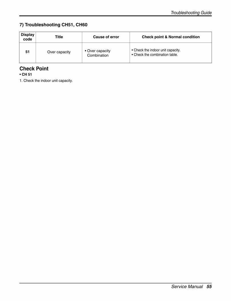
7) Troubleshooting CH51, CH60
51 Over capacity • Over capacityCombination
• Check the indoor unit capacity.• Check the combination table.
Displaycode
Title Cause of error Check point & Normal condition
Check Point• CH 51
1. Check the indoor unit capacity.
Troubleshooting Guide

56 Free Joint Multi Air Conditioner
Exploded View & Replacement Parts List
Exploded View & Replacement Parts List
1. Indoor UnitSR Chassis
346810
146811
263230-1
268716
131410
359011
342800
159901
135316
268712
159830
354210
135311
135316
267110
249951
733010
152313135314
152302
35211B
135516
W0CZZ
352150
266090
268715
352116352115
263230-2

Service Manual 57
Exploded View & Replacement Parts List
PART No.
LMNC096LRL0 LMNC126LRL0
131410 CHASSIS ASSEMBLY 3141A20006A 3141A20006A R
135311 GRILLE ASSEMBLY,DISCHARGE(INDOOR) 3531A10127A 3531A10127A R
135314 GRILLE ASSEMBLY,INLET SUB 3531A20100B 3531A20100A R
135316 GRILLE ASSEMBLY,FRONT(INDOOR) 3531A20187M 3531A20187Q R
135516 COVER ASSEMBLY,MOTOR 3551A20050P 3551A20050P R
146811 MOTOR ASSEMBLY,STEP 4681A20055A 4681A20055A R
152302 FILTER(MECH),A/C 5230A10005A 5230A10005A R
152313 FILTER ASSEMBLY,DEODORIZER 5231A20032C 5231A20032C R
159830 AIR CLEANER ASSEMBLY 5983A10009V 5983A10009V R
159901 VANE,HORIZONTAL 5990A10005A 5990A10005A R
249951 CONTROL BOX ASSEMBLY,INDOOR 4995A20361A 4995A20361G R
263230-1 THERMISTOR ASSEMBLY 6323AQ3226T 6323AQ3226T R
263230-2 THERMISTOR ASSEMBLY 6323A20004A 6323A20004A R
266090 H.V ASSEMBLY 6609A10003J 6609A10003J R
267110 REMOTE CONTROLLER ASSEMBLY 6711A20067J 6711A20067H R
268712 PWB(PCB) ASSEMBLY,DISPLAY 6871A20194A 6871A20194A R
268715 PWB(PCB) ASSEMBLY,MAIN(AC) 6871A20267B 6871A20267B R
268716 PWB(PCB) ASSEMBLY,MAIN(DC) 6871A20440A 6871A20440G R
342800 BEARING 4280A20004A 4280A20004A R
346810 MOTOR ASSEMBLY,INDOOR 4681A20062A 4681A20062A R
35211B TUBE ASSEMBLY,TUBING 5211AR7066P 5211AR7066P R
352115 TUBE ASSEMBLY,EVAPORATOR IN 5211A20470J 5211A20470J R
352116 TUBE ASSEMBLY,EVAPORATOR OUT 5211A20471D 5211A20471D R
352150 HOSE ASSEMBLY,DRAIN 5251AR2575F 5251AR2575F R
354210 EVAPORATOR ASSEMBLY,FIRST 5421A10024A 5421A10024A R
359011 FAN ASSEMBLY,CROSS FLOW 5901A20007B 5901A20007B R
733010 PLATE ASSEMBLY,INSTALL 3301A10003A 3301A10003A R
W0CZZ CAPACITOR,DRAWING 3H01487A 3H01487A R
DESCRIPTION REMARKSLOCATION
No.
Parts List(SR chassis)

58 Free Joint Multi Air Conditioner
Exploded View & Replacement Parts List
34681035211B
135516
W0CZZ
352150
267110
146811
266090
263230-1
268715
268716
131410
359011
342800
159901-1
159901-2
268712
135316
159830
135311 352111
135316
249951
733010
152313135314
152302
352115
352116
263230-2
ST Chassis

Service Manual 59
Exploded View & Replacement Parts List
PART No.
LMNC186LTL0 AMNC186LTL0 AMNH246LTL0 AMNH246LTA0 AMNC246LTL0
131410 CHASSIS ASSEMBLY 3141A10002A 3141A10002A 3141A10002A 3141A10002A 3141A10002A R
135311 GRILLE ASSEMBLY,DISCHARGE(INDOOR) 3531A10116A 3531A10116A 3531A10116A 3531A10116A 3531A10116A R
135314 GRILLE ASSEMBLY,INLET SUB 3531A20107W 3531A20107V 3531A20107W - 3531A20107V R
135316 GRILLE ASSEMBLY,FRONT(INDOOR) 3531A20207E 3531A20207F 3531A20207E 3531A24010F 3531A20207F R
135516 COVER ASSEMBLY,MOTOR 3551A20099C 3551A20099C 3551A20099C 3551A20099C 3551A20099C R
146811 MOTOR ASSEMBLY,STEP 4681A20055A 4681A20055A 4681A20055A 4681A20055A 4681A20055A R
152302 FILTER(MECH),A/C 5230A20001A 5230A20001A 5230A20001A 5230A20001A 5230A20001A R
159830 AIR CLEANER ASSEMBLY 5983A10006T 5983A10006T 5983A10006T - 5983A10006T R
159901-1 VANE,HORIZONTAL 5990A20008A 5990A20008A 5990A20008A 4995A11004D 5990A20008A R
159901-2 VANE,HORIZONTAL 5990A20009A 5990A20009A 5990A20009A 5990A20009A 5990A20009A R
249951 CONTROL BOX ASSEMBLY,INDOOR 4995A20361E 4995A20361K 4995A20361F 4995A20361F 4995A20361L R
263230-1 THERMISTOR ASSEMBLY 6323AQ3226T 6323AQ3226T 6323AQ3226T 6323AQ3226T 6323AQ3226T R
263230-2 THERMISTOR ASSEMBLY 6323A20004A 6323A20004A 6323A20004A 6323A20004A 6323A20004A R
266090 H.V ASSEMBLY 6609A10003L 6609A10003L 6609A10003L - 6609A10003L R
267110 REMOTE CONTROLLER ASSEMBLY 6711A20067J 6711A20067H 6711A20067J 6711A20083F 6711A20067H R
268712 PWB(PCB) ASSEMBLY,DISPLAY 6871A20194B 6871A20194B 6871A20194B 6871A20194B 6871A20194B R
268715 PWB(PCB) ASSEMBLY,MAIN(AC) 6871A20267B 6871A20267B 6871A20267B 6871A20267B 6871A20267B R
268716 PWB(PCB) ASSEMBLY,MAIN(DC) 6871A20440E 6871A20440L 6871A20440F 6871A20440F 6871A20440M R
342800 BEARING 4280A20004A 4280A20004A 4280A20004A 4280A20004A 4280A20004A R
346810 MOTOR ASSEMBLY,INDOOR 4681A20003D 4681A20003D 4681A20067A 4681A20067A 4681A20067A R
352111 TUBE ASSEMBLY,CONNECTOR 5211A20514B 5211A20514B 5211A20514B 5211A20514B 5211A20514B R
352115 TUBE ASSEMBLY,EVAPORATOR IN 5211A30058H 5211A30058H 5211A30097J 5211A30097J 5211A30097J R
352116 TUBE ASSEMBLY,EVAPORATOR OUT 5211A30057D 5211A30057D 5211A30098G 5211A30098G 5211A30098G R
352150 HOSE ASSEMBLY,DRAIN 5251AR2575F 5251AR2575F 5251AR2575F 5251AR2575F 5251AR2575F R
359011 FAN ASSEMBLY,CROSS FLOW 5901A20008A 5901A20008B 5901A20008A 5901A20008A 5901A20008B R
733010 PLATE ASSEMBLY,INSTALL 3301A10002A 3301A10002A 3301A10002A 3301A10002A 3301A10002A R
35211B TUBE ASSEMBLY,TUBING 5211A30439E 5211A30439E 5211A30439J 5211A30439J 5211A30439J R
W0CZZ CAPACITOR,DRAWING 3H01487G 3H01487G 3H01487G 3H01487G 3H01487G R
DESCRIPTIONSVC
CODELOCATION
No.
Parts List(ST chassis)

60 Multi type Air Conditioner
Exploded View & Replacement Parts List
352150
159901
249951
W0CZZ
266090
249941268714
733010
346810
131410
146811
135311
135080-1
135080-2
263020
668713-2
135511135313
342800
267110
266090
359011
146811-1668713-1
135316146811
145200
152302
159830
263230-1263230-2
35211B
352111
352114
352118
SU, SZ, S3 chassis(Art Cool Deluxe Type)

Service Manual 61
Exploded View & Replacement Parts List
Parts List(Art cool Deluxe Type)
PART No.
LMNC096DU*0 LMNC126DU*0 LMNC186D3*0
131410 CHASSIS ASSEMBLY 3141A20007B 3141A20007B 3141A20012A R135080-1 DECORATION (TOP) 3508A20034E 3508A20034E - R135080-2 DECORATION (BOTTOM) 3508A20034F 3508A20034F - R135311 GRILLE ASSEMBLY, DISCHARGE 3531A20137B 3531A20137B 3531A20231C R135313 GRILLE ASSEMBLY, INLET W: White - - - R
M: Metal - - - RR: Mirror 3531A21010E 3531A21010E 3531A20232B RB: Blue - - - R
D: Wood - - - RC: Cherry - - - R
135316 GRILLE ASSEMBLY, FRONT W: White - - - RM: Metal - - - RR: Mirror 3531A21027L 3531A21027L 3531A10341A RB: Blue - - - R
D: Wood - - - RC: Cherry - - - R
146811 MOTOR ASSEMBLY, STEP (Vane) 4681A20055A 4681A20055A 4681A20055A R146811-1 MOTOR ASSEMBLY, STEP (Door) 4681A20055B 4681A20055B 4681A20055D R159830 AIR CLEANER ASSEMBLY 5983A10006T 5983A10006T 5983A10006T R152302 FILTER (MECH), A/C 5230A20022A 5230A20022A 5230A20047A R159901 VANE, HORIZONTAL 5990A20015B 5990A20015B 5990A20042B R249951 CONTROL BOX ASSEMBLY 6994A20375U 6994A20375V 6994A20375W R249941 CONTROL BOX, INDOOR 4994A20067A 4994A20067A 4994A20067A R263020 PWB(PCB) ASSEMBLY W: White - - - R
M: Metal - - - RR: Mirror 6871A20463P 6871A20463P 6871A20656A RB: Blue - - - R
D: Wood - - - RC: Cherry - - - R
263230-1 THERMISTOR ASSEMBLY (Out) 6323AQ2226T 6323AQ2226T 6323AQ3226T R263230-2 THERMISTOR ASSEMBLY (Room, in) 6323A20004A 6323A20004A 6323A20004A R266090 H.V ASSEMBLY 6609A10005A 6609A10005A 6609A10005D R267110 REMOE CONTROLLER ASSEMBLY 6711A20077U 6711A20077U 6711A20077U R268714 PWB(PCB) ASSEMBLY, MAIN 6871A20684E 6871A20684N 6871A20684P R342800 BEARING 4280A20004A 4280A20004A 4280A20004A R346810 MOTOR ASSEMBLY, INDOOR 4681A20048A 4681A20048A 4681A20067C R352114 TUBE ASSEMBLY, DISTRIBUTOR 5211A202569D 5211A202569D 5211A14007A R352118 TUBE ASSEMBLY MANIFOLD 5211A20605B 5211A20605B 5211A10474D R35211B TUBE ASSEMBLY, TUBING 5211AR7066L 5211AR7066L 5211A30038Z R352150 HOSE ASEMBLY, DRAIN 5251AR1222R 5251AR1222R 5251AR1222R R354212 EVAPORATOR ASSEBLY, FINAL 5421A20105H 5421A20105H 5421A21004T R359011 FAN ASSEMBLY, CROSS FLOW 5901A20016J 5901A20016J 5901A20017C R668713 PWB ASSEMBLY, SUB 6871A20258B 6871A20258B 6871A20258B R668713 PWB ASSEMBLY, SUB 6871A20259A 6871A20259A 6871A20259A R733010 PLATE 1H00843A 1H00843A 3301A10002A RW0CZZ CAPACITOR, DRAWING 3H01487A 3H01487A 3H01487G R
DESCRIPTIONSVC
CODELOCATION
No.

62 Free Joint Multi Air Conditioner
Exploded View & Replacement Parts List
PR3 chassis (Floor Standing Type)
267110
237201
135515-1
135515-2
235811-2
235811-1
137211
132111
235512
249941
268715
W0CZZ
668713
Service Manual 63
Exploded View & Replacement Parts List
130911
35211C
354210W4811-1
354212
336610
W4810-1
730400
346810
359012
W1NHA
140570
W1WS
349480
W50400
159830337000
266000
352150
336600
269310
W4810-2
W4811-2
435512
W52103
35211A

64 Free Joint Multi Air Conditioner
Exploded View & Replacement Parts List
Parts List(Floor Standing Type)
PART No.
LMNC246PRC2 LMNC286PRC2 LMNC366PRC2
132111 FRAME ASSEMBLY 3210A20046A 3210A20046A 3210A20046A
135515-1 GRILLE ASSEMBLY, INLET 3531A10203R 3531A10203R 3531A10203R
153315-2 GRILLE ASSEMBLY, INLET 3531A10203S 3531A10203S 3531A10203S
435512 COVER ASSEMBLY, TOP(INDOOR) 3551A10022A 3551A10022A 3551A10022A
137211 PANEL ASSEMBLY, FRONT(INDOOR) 3721A10190A 3721A10190B 3721A10190L
140570 LOCKER ASSEMBLY 4A01405C 4A01405C 4A01405C
159830 AIR CLEANER ASSEMBLY 5983A10004S 5983A10004S 5983A10004S
235512 COVER ASSEMBLY, DISPLAY 3551A20135P 3551A20135P 3551A20135P
235811-1 DOOR ASSEMBLY, CLEAN 3581A20005V 3581A20005V 3581A20005V
235811-2 DOOR ASSEMBLY, CLEAN 3581A20006M 3581A20006M 3581A20006M
237201 PANEL, BASE 3720A10105H 3720A10105H 3720A10105H
249941 CONTROL BOX, INDOOR 4994A10042A 4994A10042A 4994A10042A
266000 SWITCH, PUSH 6600AP2059A 6600AP2059A 6600AP2059A
267110 REMOTE CONTROLLER 6711A20060A 6711A20060A 6711A20060A
268715 PWB(PCB) ASSEMBLY, MAIN(AC) 6871A10136X 6871A10136Y 6871A10136Z
269310 THERMISTOR ASSEMBLY 6323A20016A 6323A20016A 6323A20016A
336600 HOUSING (MECH), WRAPPER 3660A20023J 3660A20023J 3660A20023J
336610 HOUSING ASSEMBLY (MECH) 3661A20017S 3661A20017S 3661A20017S
337000 NET, STEEL 3700A30001A 3700A30001A 3700A30001A
346810 MOTOR ASSEMBLY, INDOOR 4681A20183A 4681A20134A 4681A20134A
349480 ORIFICE 4948A20008B 4948A20008B 4948A20008B
352150 HOSE ASSY, DRAIN 5251AR1222X 5251AR1222X 5251AR1222X
35211C TUBE ASSY, DISCHARGE (INDOOR) 5211A20854C 5211A20854C 5211A20854C
354210 EVAPORATOR ASSEMBLY, FIRST 5421A20039Q 5421A20039Q 5421A20039Q
359012 FAN ASSEMBLY, TURBO 5901A20021A 5901A20021A 5901A20021A
668713 PWB(PCB) ASSEMBLY, SUB 6871AQ3212D 6871AQ3212D 6871AQ3212D
730400 BASE, INSTALL 3040A20067B 3040A20067B 3040A20067B
753010 HEATER ASSEMBLY, ELECTRIC - - -
W0CZZ CAPACITOR, DRAWING 3H00660N 3H00660N 3H00660N
W1NHA NUT, HEXAGON 1NHA0801206 1NHA0801206 1NHA0801206
W1WS WASHER, SPRING LOCK 1WSD0800030 1WSD0800030 1WSD0800030
W4810-1 BRACKET 4810A20142A 4810A20142A 4810A20142A
W4810-2 BRACKET 4810A10008A 4810A10008A 4810A10008A
W4811-1 BRACKET ASSEMBLY 4811A30011B 4811A30011B 4811A30011B
W4811-2 BRACKET ASSEMBLY 4811A30021A 4811A30021A 4811A30021A
W50400 RUBBER 5040A30031A 5040A30031A 5040A30031A
W52103 TUBE, DISTRIBUTOR 2H00351T 2H00351T 2H00351T
35211A TUBE ASSEMBLY, SUCTION INDOOR 5211A20851C 5211A20851C 5211A20851C
DESCRIPTION REMARKSLOCATION
No.

Service Manual 65
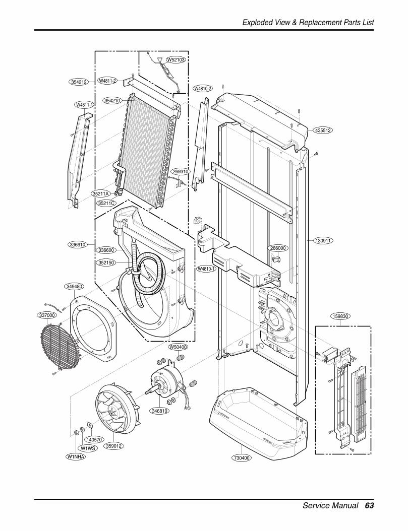
Exploded View & Replacement Parts List
L4UC488FA0
2. Outdoor Unit
437212
435512658740
W0CCZ-1
W0C
CZ-2
669200
447910430410
546810
435301
548490
552113
352112
552114
263230-2
263230-1
546810
554031
559010
668711649950
437210
435511237204
554160-2
554160-1
552115-2552115-1
552203-1
552203-2
561411-1
561411-2
561411-3
561411-4

66 Free Joint Multi Air Conditioner
Exploded View & Replacement Parts List
Parts List(L4UC488FA0)
PART No.
L4UC488FA0
430410 BASE ASSEMBLY,WELD[OUTDOOR] 3041A20047F R
554031 CONDENSER ASSEMBLY,BENT 5403A20230B R
554160-1 COMPRESSOR 2520UHLT2BA R
554160-2 COMPRESSOR - R
552112 TUBE ASSEMBLY,CONDENSER IN 5211A15004A R
552113 TUBE ASSEMBLY,CONDENSER OUT 5211A15005A R
552203-1 VALVE,SERVICE 2H02479B R
552203-2 VALVE,SERVICE 2H01890W R
552203-3 VALVE,SERVICE - R
561411 COIL ASSEMBLY,EXPANSION 6140A90001P R
263230-1 THERMISTOR ASSEMBLY 6323A20020A R
263230-2 THERMISTOR ASSEMBLY 6323A20039A R
548490 ACCUMULATOR ASSEMBLY(MECH) 4949A10048B R
552114 TUBE ASSEMBLY,DISCHARGE (OUTDOOR) 5211A16005A R
447910 BARRIER ASSEMBLY,OUTDOOR 4760AP1216L R
561411-1 COIL ASSEMBLY,EXPANSION 6141A20037A R
561411-2 COIL ASSEMBLY,EXPANSION 6141A20037B R
561411-3 COIL ASSEMBLY,EXPANSION 6141A20037C R
561411-4 COIL ASSEMBLY,EXPANSION 6141A20037D R
561411-5 COIL ASSEMBLY,EXPANSION - R
649950 CONTROL BOX ASSEMBLY,OUTDOOR 4995A20166M R
668711 PWB(PCB) ASSEMBLY,MAIN(OUTDOOR) 6871A20583U R
W0CZZ-1 CAPACITOR,DRAWING 2A00986D R
W0CZZ-2 CAPACITOR,DRAWING - R
546810 MOTOR ASSEMBLY,OUTDOOR 4681A20028J R
559010 FAN ASSEMBLY,PROPELLER 5901A10032A R
435511 COVER ASSEMBLY,CONTROL(OUTDOOR) 3A01293X R
435512 COVER ASSEMBLY,TOP(OUTDOOR) 3550AP1213B R
437212 PANEL ASSEMBLY, REAR(OUTDOOR) 3720AP1202L R
137213-1 PANEL ASSEMBLY,SIDE - R
137213-2 PANEL ASSEMBLY,SIDE 3720AP1215E R
437214 PANEL ASSEMBLY,FRONT(OUTDOOR) - R
437210 PANEL ASSEMBLY,FRONT(OUTDOOR) 3720A1212B R
435301 GRILLE,DISCHARGE 3530AP1225D R
W49810 SUPPORTER ASSEMBLY 4981A11008A R
552115-1 TUBE ASSEMBLY,MENIFOLD(OUTDOOR) - R
552115-2 TUBE ASSEMBLY,MENIFOLD(OUTDOOR) - R
DESCRIPTION REMARKSLOCATION
No.

P/No.: 3828A22020B
July, 2005
Printed in Korea