Embed Size (px)
Citation preview

LETTER OF TRANSMITTAL
DATE: September 27, 2013
TO: Dr. Linda Hanagan
Lhanagan.engr.psu.edu
FROM: Alyssa Stangl
ENCLOSED: AE 481W – Senior Thesis | Structural Technical Report 2
Dear Dr. Hanagan,
This report was prepared to be submitted for Technical Report 2 for AE 481W – Senior Thesis.
It includes a thorough calculation and analysis of all dead and live gravity loads, wind loads, and
seismic loads. The report was created using a combination of hand written calculations and
excel spreadsheets. The calculations were summarized for the lateral loads in loading diagrams
at the end of each section.
Thank you for your time reviewing this report. I look forward to discussing it with you in the
near future.
Sincerely,
Alyssa Michelle Stangl

Technical Report 2
Alyssa Stangl | Structural Option | Advisor: Dr. Linda Hanagan
La Jolla Commons Phase II Office Tower San Diego, California
September 27, 2013

Tech
hnical Re
Table oExecutive
Site Plan a
Abstract ..
Documen
Gravity Lo
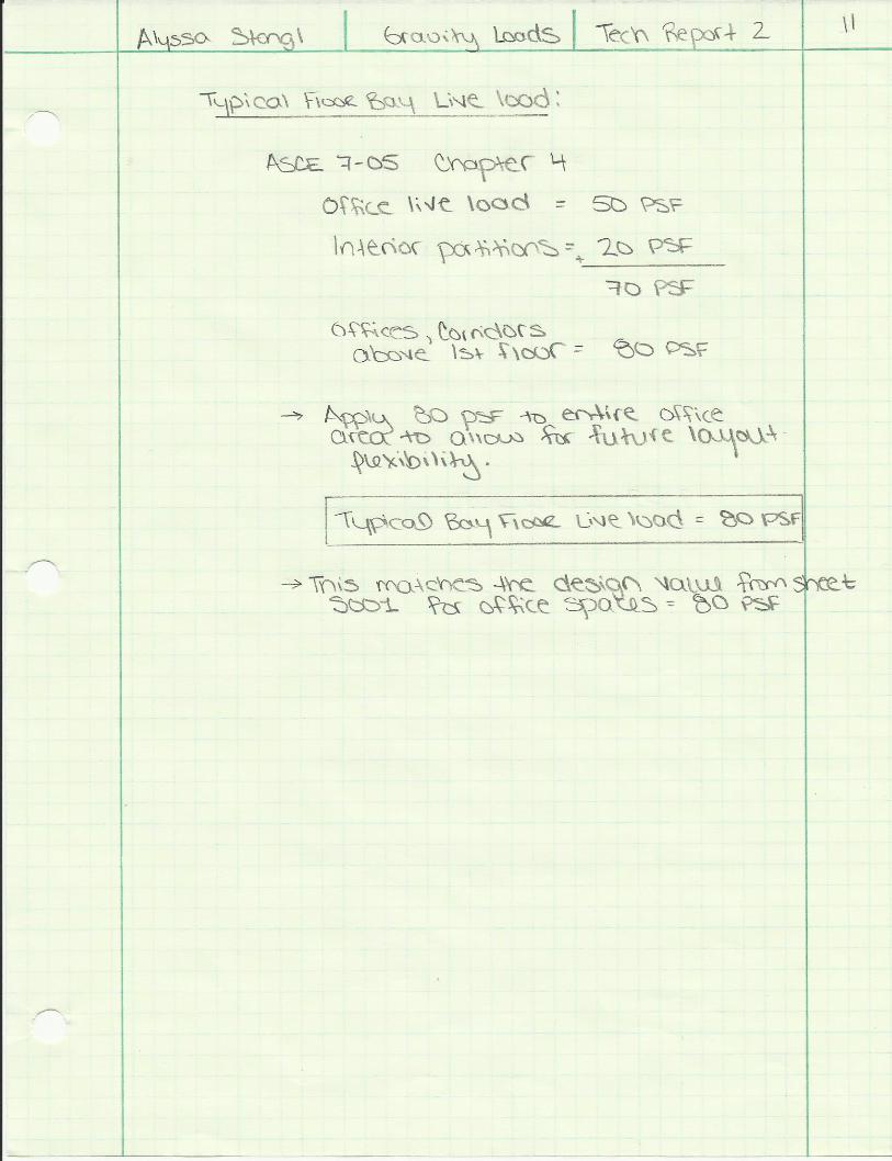
Typic
Typic
Non‐
Typic
Wind Loa
Hand
Exce
Wind
Seismic Lo
Hand
Exce
Seism
eport 2 |
f Contents Summary ....
and Location
.....................
ts Used to Cr
oad Calculatio
cal Roof Bay .
cal Floor Bay
‐Typical Floor
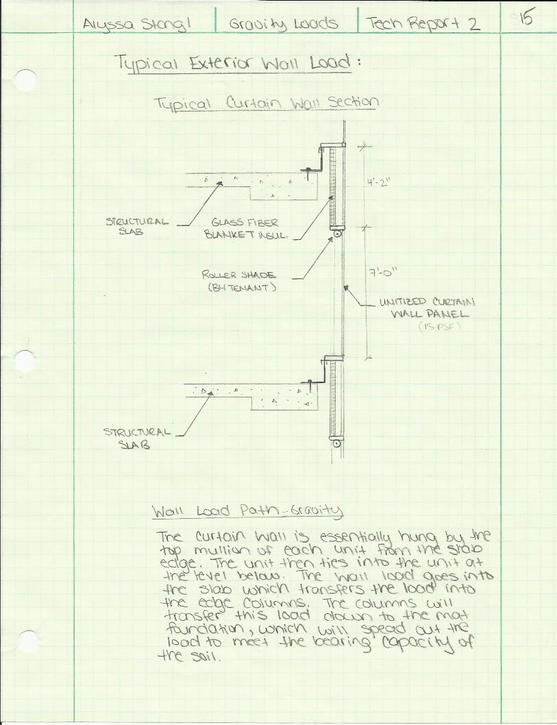
cal Exterior W
d Calculation
d Calculations
l Spreadshee
d Load Summ
oad Calculatio
d Calculations
l Spreadshee
mic Load Sum
La Jolla Co
s .....................
.....................
.....................
reate this Rep
ons ................
.....................
.....................
r Loads ..........
Wall ..............
s ...................
s ...................
t ...................
mary ...............
ons ...............
s ...................
t ...................
mmary ...........
ommons Pha
.....................
.....................
.....................
port ...............
.....................
.....................
.....................
.....................
.....................
.....................
.....................
.....................
.....................
.....................
.....................
.....................
.....................
ase II Office
......................
......................
......................
......................
......................
......................
......................
......................
......................
......................
......................
......................
......................
......................
......................
......................
......................
e Tower
.....................
.....................
.....................
.....................
.....................
.....................
.....................
.....................
.....................
.....................
.....................
.....................
.....................
.....................
.....................
.....................
.....................
.....................
.....................
.....................
.....................
.....................
.....................
.....................
.....................
.....................
.....................
.....................
.....................
.....................
.....................
.....................
.....................
.....................
2 | P
Alyssa Stan
......................
......................
......................
......................
......................
......................
......................
......................
......................
......................
......................
......................
......................
......................
......................
......................
......................
a g e
ngl [Structu
....... 3
....... 4
....... 5
....... 6
....... 7
....... 8
..... 10
..... 12
..... 15
..... 17
..... 18
..... 28
..... 31
..... 33
..... 34
..... 37
..... 39
ural]

3 | P a g e
Alyssa Stangl [Structural]
Executive Summary
La Jolla Commons Phase II Office Tower is a 13 story office building in San Diego, California. Each floor is
about 40,320 square feet, and the structure reaches 198 feet from ground level to the top of the
penthouse. With two levels of underground parking, the building extends about 20 feet below grade.
Acting as an office building for LPL Financial, the building has open floor plans and large areas of glass
curtain wall. La Jolla Commons Tower II received a LEED-CS Gold Certification and is the nation’s largest
and most advanced net-zero office building.
The building’s gravity system begins with a mat foundation, two stories below grade. The mat
foundation was chosen for its constructability, when compared to a system of footers and grade beams.
The super structure consists of two way, flat plate, concrete slabs on a rectangular column grid. A
typical bay is 30 feet by 40 feet. Each level varies in thickness – 18, 14, or 12 inches, reinforcing was
used as required by code. Camber was used for the slab at each level (except Lower Level 2 where the
mat foundation serves as the floor). This was done because large construction loads crack the slab,
causing considerable deflections after construction and finishes are completed. Camber ranges from ¼
inch at the exterior edge of a bay to 2 ¼ inches at the center of the bay, creating an essentially flat slab
after building loads have been applied.
Laid out at the core of the building, the lateral system of La Jolla Commons Tower II consists of
reinforced concrete shear walls. Due to the high shear forces associated with earthquake loading in this
Seismic Category D structure, the diaphragm is not relied upon to transfer lateral loads to the shear wall
system; therefore, collector beams are used to aid in load transfer.
La Jolla Commons Tower II has two unique structural and architectural features. The north and south
sides of the building feature 15 foot cantilevers that start at Level 3 and continue up to the roof level.
The structure is similar to that of the rest of slab; however, it does have additional reinforcement and a
thickened slab edge, creating a back-span for the cantilever. Also, the building has a plaza area on the
Ground Level which essentially carves out a portion of the Ground Level and Level 2. Main building
columns are exposed here, and additional 18 inch columns are added to support the slab edge above.
La Jolla Commons Tower II was designed using the 2010 California Building Code which corresponds to
ASCE 7-05 and ACI 318-08. CBC 2010 and ASCE 7-05 were used to calculate live, wind, and earthquake
loads. ACI 318 – 08, Chapter 21, references the design of concrete Earthquake-Resistant structures, and
ASCE 7-05, Chapter 12, details the Seismic Design Requirements for Building Structures. Both of these
documents were used heavily in the design of LJC II in order to account for seismic loading and detailing.
La Jolla Commons Phase II Office Tower is full of educational value. It has several structural challenges
and unique conditions– punching shear, seismic loading and detailing, concrete shear wall design, and
computer modeling.

4 | P a g e
Alyssa Stangl [Structural]
Building Site Information
Building Site Plan (Courtesy of Hines)
San Diego California (Google Maps)

5 | P a g e
Alyssa Stangl [Structural]

6 | P a g e
Alyssa Stangl [Structural]
Documents Used to Create This Report
California Building Code 2010
o Adopts IBC 2009 with some modifications
American Society of Civil Engineers
o ASCE 7-05 – Minimum Design Loads for Buildings
La Jolla Commons Phase II Office Tower
o Construction Documents
o Technical Specifications

Alyssa Stangl [Structural]
GRAVITY LOAD
CALCULATIONS


Alyssa Stangl [Structural]
WIND LOAD
CALCULATION


Alyssa StanglTechnical Report 2 Due: 9/27/13
Equations Utilized: Constants Previously Calculated by hand:Kz = 2.01 (z/zg)
2/α kzt = 1.00
qz = 0.00256KzKztKdV2I kd = 0.85
p=qGfCp (MWFRS for Flexible Buildings) V = 85.0I = 1.00
Gf, NS= 0.903Gf, EW= 0.853
Floor Number Height above ground (z) zg α kz qz qh2 15.00 900 9.5 0.85 13.36 22.993 28.17 900 9.5 0.97 15.24 22.994 41.34 900 9.5 1.05 16.52 22.995 54.51 900 9.5 1.11 17.51 22.996 67.68 900 9.5 1.17 18.33 22.997 80.85 900 9.5 1.21 19.03 22.998 94.02 900 9.5 1.25 19.64 22.999 107.19 900 9.5 1.28 20.19 22.9910 120.36 900 9.5 1.32 20.69 22.9911 133.53 900 9.5 1.35 21.15 22.9912 146.70 900 9.5 1.37 21.57 22.9913 159.87 900 9.5 1.40 21.96 22.99
Penthouse Floor 173.04 900 9.5 1.42 22.33 22.99Penthouse Roof 198.67 900 9.5 1.46 22.99 22.99
Caclulating kz and qz ‐ NS and SW
WIND LOADING CALCULATIONS

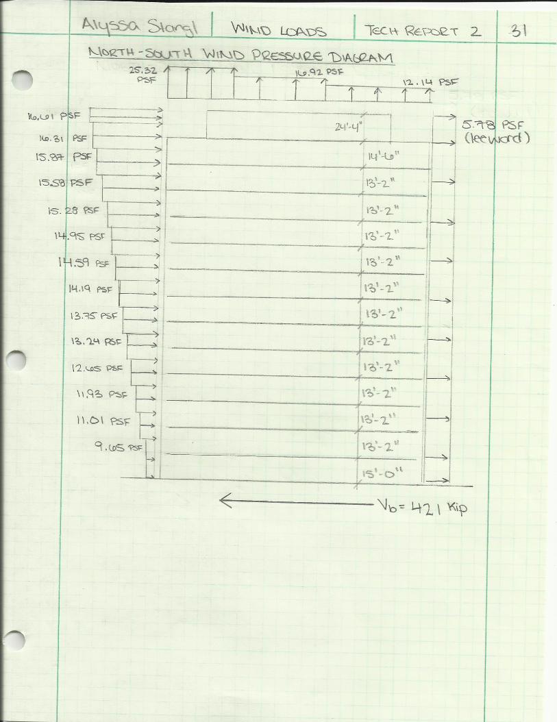
Floor Number Height above ground (z) qz qh Windward (PSF) Leeward (PSF) Trib HeightTrib Area
(SF) Force (k) Story Shear (K)Overturning Moment
(ft‐k)
Ground 0.00 13.36 22.99 9.65 ‐5.78 7.50 2092.50 32.30 421.44 0.002 15.00 13.36 22.99 9.65 ‐5.78 14.09 1619.78 25.00 389.14 375.033 28.17 15.24 22.99 11.01 ‐5.78 13.17 1514.55 25.43 364.14 716.384 41.34 16.52 22.99 11.93 ‐5.78 13.17 1514.55 26.83 338.71 1109.275 54.51 17.51 22.99 12.65 ‐5.78 13.17 1514.55 27.92 311.87 1521.736 67.68 18.33 22.99 13.24 ‐5.78 13.17 1514.55 28.81 283.96 1949.837 80.85 19.03 22.99 13.74 ‐5.78 13.17 1514.55 29.57 255.15 2391.098 94.02 19.64 22.99 14.19 ‐5.78 13.17 1514.55 30.25 225.57 2843.779 107.19 20.19 22.99 14.59 ‐5.78 13.17 1514.55 30.85 195.33 3306.5810 120.36 20.69 22.99 14.95 ‐5.78 13.17 1514.55 31.39 164.48 3778.5111 133.53 21.15 22.99 15.28 ‐5.78 13.17 1514.55 31.89 133.08 4258.7612 146.70 21.57 22.99 15.58 ‐5.78 13.17 1514.55 32.36 101.19 4746.6813 159.87 21.96 22.99 15.87 ‐5.78 13.84 1591.03 34.44 68.83 5506.40
Penthouse Floor 173.04 22.33 22.99 16.13 ‐5.78 19.42 1196.30 26.22 34.39 4536.56Penthouse Roof 198.67 22.99 22.99 16.61 ‐5.78 12.17 365.10 8.17 8.17 1624.11
Base Shear [k] = 421Total Overturning Moment [ft‐k] = 38665
Windard Wall Cp= 0.800 L= 279.00Leeward Wall Cp= ‐0.279 B= 115.00
(interpolate) L/B= 2.43
Floor Number Height above ground (z) qz qh Windward (PSF) Leeward (PSF) Trib HeightTrib Area
(SF) Force (k) Story Shear (K)Overturning Moment
(ft‐k)
1 0.00 13.36 22.99 9.12 ‐10.38 7.50 862.5 16.82 1166.73 02 15.00 13.36 22.99 9.12 ‐10.38 14.09 3929.7 76.63 1149.91 1149.433 28.17 15.24 22.99 10.40 ‐10.38 13.17 3674.4 76.35 1073.28 2150.904 41.34 16.52 22.99 11.27 ‐10.38 13.17 3674.4 79.57 996.93 3289.345 54.51 17.51 22.99 11.95 ‐10.38 13.17 3674.4 82.05 917.36 4472.626 67.68 18.33 22.99 12.51 ‐10.38 13.17 3674.4 84.10 835.31 5691.767 80.85 19.03 22.99 12.98 ‐10.38 13.17 3674.4 85.85 751.21 6941.058 94.02 19.64 22.99 13.40 ‐10.38 13.17 3674.4 87.39 665.36 8216.509 107.19 20.19 22.99 13.78 ‐10.38 13.17 3674.4 88.77 577.97 9515.1610 120.36 20.69 22.99 14.12 ‐10.38 13.17 3674.4 90.02 489.20 10834.7411 133.53 21.15 22.99 14.43 ‐10.38 13.17 3674.4 91.17 399.18 12173.4012 146.70 21.57 22.99 14.72 ‐10.38 13.17 3674.4 92.23 308.01 13529.6213 159.87 21.96 22.99 14.99 ‐10.38 13.84 3860.0 97.92 215.79 15654.63
Penthouse Floor 173.04 22.33 22.99 15.24 ‐10.38 19.42 3300.3 84.55 117.87 14631.08Penthouse Roof 198.67 22.99 22.99 15.69 ‐10.38 12.17 1277.9 33.31 33.31 6618.37
Base Shear [k]= 1167Total Overturning Moment [ft‐k] = 114869
Windard Wall Cp= 0.800 L= 115.00Leeward Wall Cp= ‐0.500 B= 279.00
Wind Pressures | North‐South Direction
Wind Pressures | East‐West Direction
Wall Pressures | NORTH‐SOUTH DIRECTION
Wall Pressures | EAST‐WEST DIRECTION

Location on Roof Cp G qh Pressure [PSF]
0 to 99.34 ft ‐1.2194 0.903 22.99 ‐25.32 <‐ Area Reduction Applies for Cp = 99.34*115=11424.1 ft2
99.34 to 198.67 ft ‐0.8152 0.903 22.99 ‐16.92198.67 to 279 ft ‐0.5848 0.903 22.99 ‐12.14
h= 198.67L= 279
h/L= 0.712
NOTE: Interpolation between h/L=0.5 and h/L=1.0 can be seen on Page 18 of hand calculations. Also, Area reduction calculation can be seen on Page 18.
Location on Roof Cp G qh Pressure [PSF]
0 to 99.34 ft: ‐1.040 0.853 22.99 ‐20.40 <‐ Area Reduction Applies for Cp= 99.34*279=27716 ft2
99.34 to 115 ft: ‐0.700 0.853 22.99 ‐13.73
h= 198.67L= 115
h/L= 1.728
NOTE: Area reduction application calculation can be seen on Page 19 of hand calculations.
Wind Pressures ‐ Roof Uplift | East West
Roof Wind Uplift | EAST‐WEST DIRECTION
Roof Wind Uplift | NORTH‐SOUTH DIRECTION
Wind Pressures ‐ Roof Uplift | North South


Tech
hnical Re
eport 2 | La Jolla Coommons Pha
SEISM
CALC
ase II Office
MIC LO
CULATIO
e Tower
OAD
ON
Alyssa Stan
ngl [Structuural]


Alyssa StanglTechnical Report 2 Due: 9/27/13
Floor Number Dead Load Partition Load Total Weight (PSF) Floor Area (ft2) Weight (kip)Penthouse Roof 133 0 133 6704 892Penthouse Floor 171 0 171 29703 5079
13 215 20 235 29703 698012 215 20 235 29703 698011 215 20 235 29703 698010 215 20 235 29703 69809 215 20 235 29703 69808 215 20 235 29703 69807 215 20 235 29703 69806 215 20 235 29703 69805 215 20 235 29703 69804 215 20 235 29703 69803 215 20 235 29703 69802 215 20 235 26494 6226
Total Weight = 88979
Floor Weight Calculation
SIESMIC LOAD CALCULATIONS

T= 1.056 s
k= 1.278Vb= 6406.5 k
Floor Number hi (ft) h (ft) W (kip) W*hk CvxStory Forces Fi
(kip)
Penthouse Roof 24.33 198.70 892 771405 0.0248 158.68Penthouse Floor 14.50 174.37 5079 3718753 0.1194 764.93
13 13.17 159.87 6980 4573855 0.1469 940.8312 13.17 146.70 6980 4097943 0.1316 842.9311 13.17 133.53 6980 3633774 0.1167 747.4510 13.17 120.36 6980 3182178 0.1022 654.569 13.17 107.19 6980 2744134 0.0881 564.468 13.17 94.02 6980 2320832 0.0745 477.397 13.17 80.85 6980 1913741 0.0614 393.656 13.17 67.68 6980 1524742 0.0490 313.635 13.17 54.51 6980 1156338 0.0371 237.854 13.17 41.34 6980 812063 0.0261 167.043 13.17 28.17 6980 497389 0.0160 102.312 15.00 15.00 6226 198271 0.0064 40.78
SUM: 88979 31145418 6406.5
Base Shear [k] = 6406.5
Story Forces | North‐South
Seismic Story Forces