Embed Size (px)
Citation preview

Solutions for Today | Options for Tomorrow
A Combined Computational and ExperimentalApproach to Mixed Matrix Membranes for CO2 CaptureDave Hopkinson, Surendar Venna, Ali Sekizkardes, SamehElsaidi, Samir Budhathoki, Jan Steckel, and many others
Month 31, 2016

2
Robeson Upper Bound
Membranes need very high performance to be used in CO2 capture from fossil energy
Polymer Inorganic filler
Lloyd M.Robeson, Journal of Membrane Science, 320, 2008, 390-400Performance vs cost plot, Courtesy: William Koros
Permeance of 4000 GPU, CO2/N2 selectivity of 25For 10% COE reduction compared with reference plant
Challenge: Need to process large amount of gases with low available driving force
Mixed Matrix MembranePotential
MixedMatrix
Membranes
CO2 Permeability (Barrer)C
O2/N
2Se
lect
ivity

3
MMMs can increase membrane performance beyond the Robeson Upper Bound
1
10
100
1 10 100 1000 10000 100000
CO2/
N2
sele
ctiv
ity
CO2 Permeability (Barrer)
Matrimid-UiO-66polyphosphazene-SIFSIXPIM-BILPIXPE-Silica gel
Robeson upper bound
NETL Polymer 1NETL Polymer 2
NETL Polymer 3
MMM performance
Assumptions of Robeson UB: pure polymers; 35 ⁰C; pure gas; solution-diffusion

4
Normally filler particles are paired with polymers by chemical intuition
How do we choose the best pair of polymer and filler particle?
UiO-66
Polyphosphazenes
SIFSIX POP
Ionic XL Polyethers Microporous Polymers
n
N N
O
nO
OO
O
Polyimide
Silica

5
According to the Maxwell Model, properties of the polymer and filler must be complementary
0
5
10
15
20
25
30
35
40
45
1E+00 1E+01 1E+02 1E+03 1E+04 1E+05 1E+06 1E+07Filler Particle Permeability (Barrer)
MMM CO2 Permeability (Barrer) MMM CO2/N2 Selectivity
Matrimid CO2 Permeability = 10 BarrerMatrimid CO2/N2 selectivity = 30
Matrimid with 23% filler particle
CO2/N2 Selectivity
CO2 Permeability
InterfaceRpolymer
Rseive
Assumptions of Maxwell Model:• Resistors in series• No particle agglomeration• Low particle loading, spherical• Ideal interface
𝑃𝑃𝑒𝑒𝑒𝑒𝑒𝑒 = 𝑃𝑃𝑐𝑐𝑃𝑃𝑑𝑑 + 2𝑃𝑃𝑐𝑐 − 2∅𝑑𝑑 𝑃𝑃𝑐𝑐 − 𝑃𝑃𝑑𝑑𝑃𝑃𝑑𝑑 + 2𝑃𝑃𝑐𝑐 + ∅𝑑𝑑 𝑃𝑃𝑐𝑐 − 𝑃𝑃𝑑𝑑
• For optimum selectivity, permeability of particle should be < 100X greater than polymer
• MMM permeability improvement has limitations
Journal of Molecular Structure 739 (2005) 87–98

6
Computational modeling is used to predict MOF and MMM properties

7
A database of 137,000 hypothetical MOFs was made by combining MOF building blocks
2: Organic Linkers1: Metal Center
Building blocks re-combined using simple geometrical rules
to create periodic, 3D structures
C. E. Wilmer et al., Nature Chemistry, 2012, 4, 83–89.
3: Functional Groupse.g. –Br, -Cl, phenyl, etc.

8
• Automated screening of the Cambridge Structural Database was used to clean experimentally obtained structure files:
• Solvent molecules removed• Other disorder removed
• 6,000 structures available in CoRE database• We have completed calculations on ~2,500 CoRE MOFs
The CoRE database details properties of MOFs that have been synthesized before
Y. G. Chung et al., Chemistry of Materials, 2014, 26 (21), 6185–6192.

9
Permeability of MOFs is calculated based on pore geometry
S. Budhathoki, A. Ajayi, C. E. Wilmer, and J. Steckel, in preparation.
MOFs from the hypothetical and CoRE databases are analyzed
based on largest cavity diameter (LCD), pore limiting diameter
(PLD), and surface area
Grand Canonical Monte Carlo simulations are used to calculate CO2 and N2 solubility for rigid MOFs
Molecular dynamics simulations are used to calculate CO2 and N2 diffusivity
Pore Limiting Diameter
Solubility Diffusivity
MOF Permeability = Solubility X DiffusivityMixed Matrix Membrane Permeability is from the Maxwell Model

10
Predictions of MMM permeability are in good agreement with literature data
Blue markers = CO2 permeability; Green markers = N2 permeability

11
• For low permeability polymers, any MOF leads to an increase in permeability• For high permeability polymers, only some MOFs will cause an improvement in permeability and selectivity
CO2 permeability and CO2/N2 selectivity is calculated for MMMs with hypothetical MOFs
CO2 Permeability (Barrer)
CO
2/N2
Sele
ctiv
ity
12
• Cost Reduction from ~$63 to ~$48 per tonne CO2• Reduction of ~24%
Compared to pure polymer, MMMs can dramatically reduce the cost of capture
CO2 removal system: 2 stage membrane
with air sweepNETL Polymer 3
MMM

13
Many of the MOFs in the CoRE database are sorption selective to CO2 over H2O
Henry’s Constants for H2O in CoRE MOFs courtesy of:Li, S.; Chung, Y. G.; Snurr, R. Q. High-Throughput Screening of Metal–Organic Frameworks for CO 2 Capture in the Presence of Water. Langmuir 2016, 32 (40), 10368–10376.
neat polymer neat polymer

14
There are many practical considerations for a high performance membrane
Support with optimum pore size and density
High performance polymer
1
4
3
2
Ultra-thin, defect-free selective layer
Nano-size MOF with matched properties
15
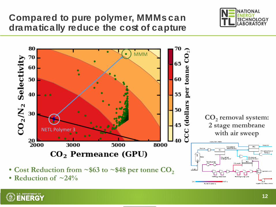
A high performance MMM requires a high performance polymer
1
10
100
1 10 100 1000 10000
CO2/
N2
sele
ctiv
ity
CO2 Permeability (Barrer)
2013: Ionic crosslinkedpolyethers
2014:Polyphosphazenes
2015: NETL Polymer 1 and 2
2016: PIM-1
2017: NETL Polymer 3
2012: Matrimid30
Venna et al., J. Membr. Sci., 535, 2017, 103–112Zhou et al, European Polymer Journal, 84, 2016, 65–76

16
A hollow fiber support needs optimized pore density and pore size
Optimum wall thickness and bore diameter
Higher surface pore density with optimum pore size
The support should have at least an order of magnitude higher gas flux compared to selective layer
17
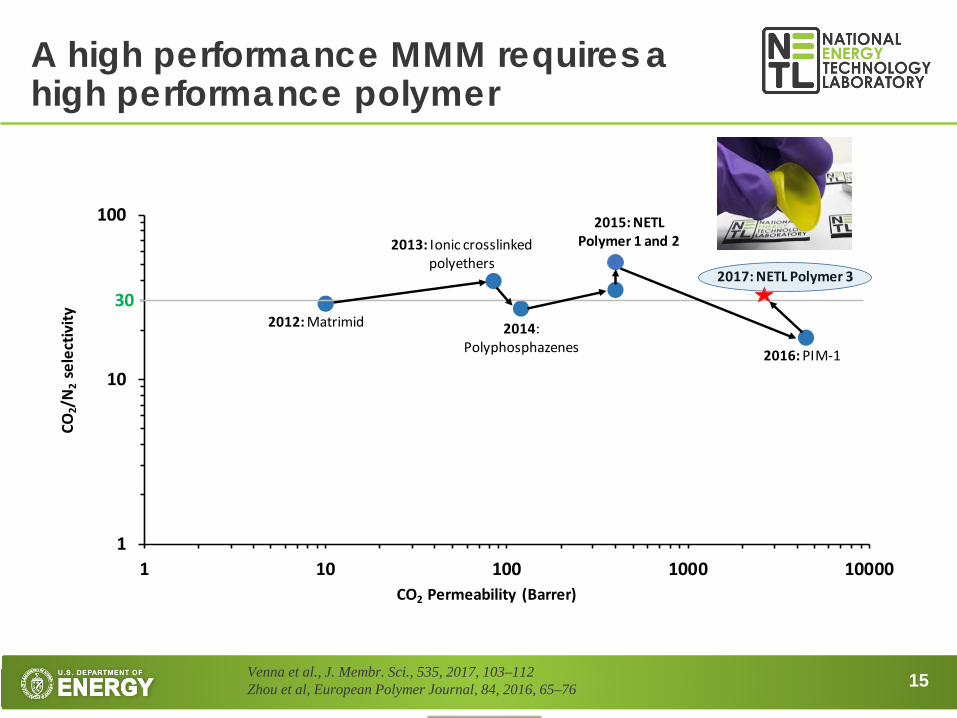
What is the max allowable selective layer thickness needed to achieve our performance goals?
Lloyd M.Robeson, Journal of Membrane Science, 320, 2008, 390-400
1
10
100
10 100 1,000 10,000
CO2 Permeability (Barrer)
CO2/
N2
sele
ctiv
ityNETL Polymer 3
0.6 µm
NETL Polymer 3 MMM
1 µm
Thickness needed for NETL Polymer 3 to achieve 4000 GPU is ~ 600 nmFor the NETL Polymer 3 MMM, the thickness needed is > 1000 nm
Region of interest
18
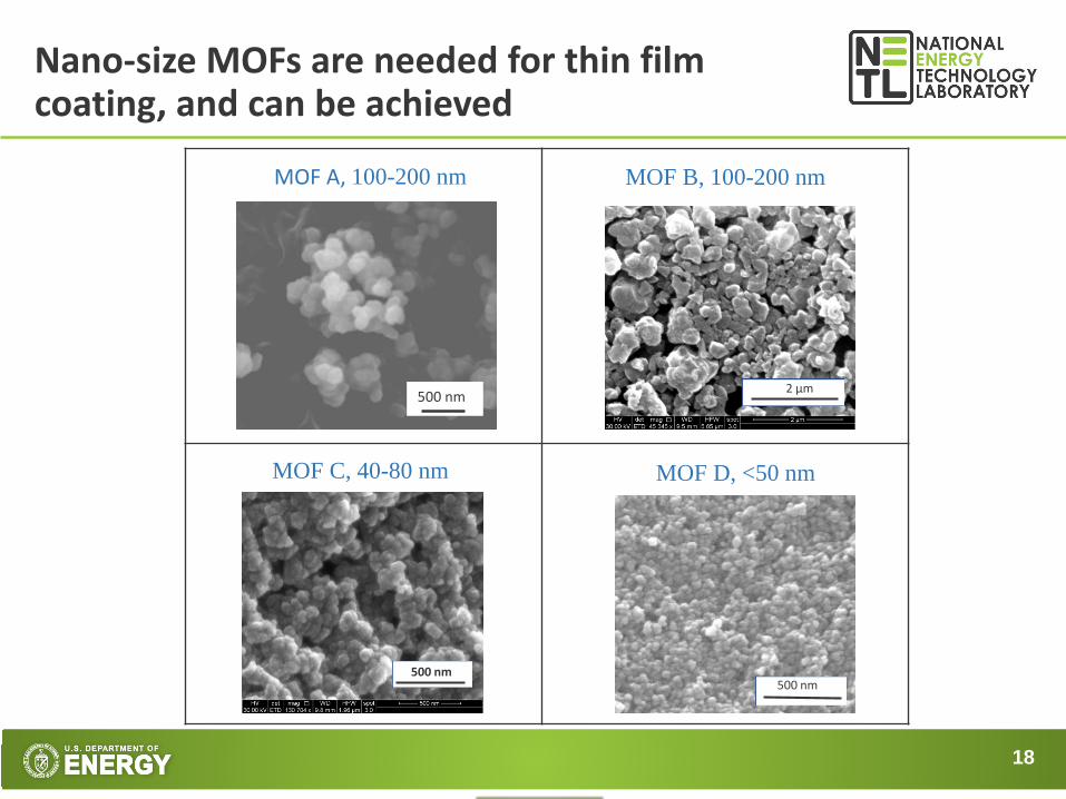
Nano-size MOFs are needed for thin film coating, and can be achieved
500 nm
MOF A, 100-200 nm
500 nm
MOF D, <50 nm
MOF B, 100-200 nm
MOF C, 40-80 nm
500 nm
2 µm
19
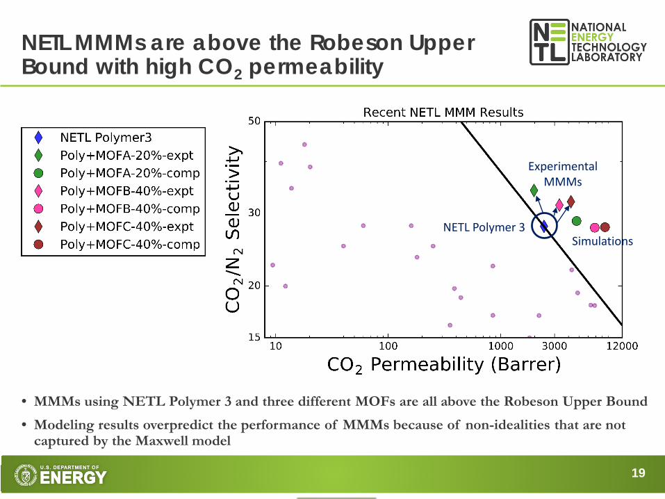
• MMMs using NETL Polymer 3 and three different MOFs are all above the Robeson Upper Bound• Modeling results overpredict the performance of MMMs because of non-idealities that are not
captured by the Maxwell model
NETL MMMs are above the Robeson Upper Bound with high CO2 permeability
NETL Polymer 3
ExperimentalMMMs
Simulations
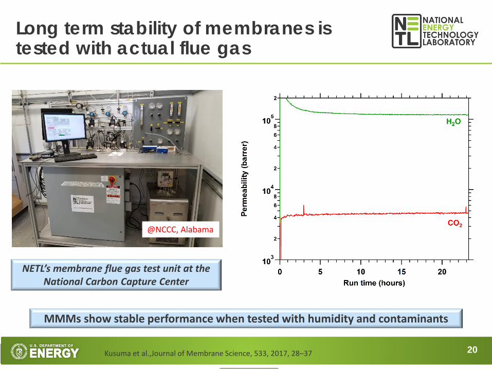
20Kusuma et al.,Journal of Membrane Science, 533, 2017, 28–37
NETL’s membrane flue gas test unit at the National Carbon Capture Center
@NCCC, Alabama
Long term stability of membranes is tested with actual flue gas
MMMs show stable performance when tested with humidity and contaminants

21
Future work is to scale up to a small hollow fiber module tested with flue gas
A Simple Fabrication Method for Mixed Matrix Membranes with In-situ MOF Growth for Gas Separation, Anne M. Marti, Surendar R. Venna, Elliot A. Roth, Jeffrey T. Culp, and David P. Hopkinson, ACS Applied Materials and Interfaces
In-situ MOF growth is a possible scheme for reducing steps for scale-up manufacturing of mixed matrix membranes

22
Summary: NETL has taken a multifaceted approach to MMM development for low cost CO2 capture
• Using high throughput computational techniques, properties of polymer/MOF can be matched to make better MMMs
• For an NETL polymer, the cost of capture can be reduced from $61 to $46/tonne CO2
• MMMs have been tested at NCCC with real flue gas and show stable performance
• MMMs developed at NETL are above the Robeson Upper Bound
• High permeance hollow fiber supports have been fabricated
• Techniques for thin film coatings are being developed
23
Thanks to our team!MOF development:Sameh ElsaidiJeff CulpNathaniel RosiPatrick Muldoon
Polymer development:Ali SekizkardesJames BakerMegan Macala
Simulations and economic analysis:Olukayode AjayiSamir BudhathokiJan SteckelWei ShiChristopher Wilmer
Membrane fabrication and testing:Victor KusumaFangming XiangShouliang YiHyuk Taek KwonLingxiang ZhuZi Tong
Team leads:Dave HopkinsonKevin Resnik
Program management:Lynn BrickettJohn Litynski
Acknowledgement:This project was funded by the Department of Energy, National Energy Technology Laboratory, an agency of the United States Government, under the Carbon Capture Field Work Proposal and in part through a support contract with AECOM (DE-FE0004000). Neither the United States Government nor any agency thereof, nor any of their employees, nor AECOM, nor any of their employees, makes any warranty, expressed or implied, or assumes any legal liability or responsibility for the accuracy, completeness, or usefulness of any information, apparatus, product, or process disclosed, or represents that its use would not infringe privately owned rights. Reference herein to any specific commercial product, process, or service by trade name, trademark, manufacturer, or otherwise, does not necessarily constitute or imply its endorsement, recommendation, or favoring by the United States Government or any agency thereof. The views and opinions of authors expressed herein do not necessarily state or reflect those of the United States Government or any agency thereof.
Past team members:Anne MartiJie FengGanpat DaheDave LuebkeHunaid NulwalaErik AlbenzeAlex Spore