Embed Size (px)
Citation preview
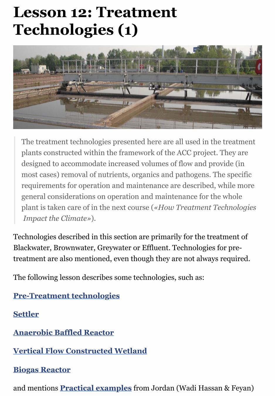
Lesson 12: TreatmentTechnologies (1)
The treatment technologies presented here are all used in the treatmentplants constructed within the framework of the ACC project. They aredesigned to accommodate increased volumes of flow and provide (inmost cases) removal of nutrients, organics and pathogens. The specificrequirements for operation and maintenance are described, while moregeneral considerations on operation and maintenance for the wholeplant is taken care of in the next course («How Treatment Technologies Impact the Climate»).
Technologies described in this section are primarily for the treatment ofBlackwater, Brownwater, Greywater or Effluent. Technologies for pre-treatment are also mentioned, even though they are not always required.
The following lesson describes some technologies, such as:
Pre-Treatment technologies
Settler
Anaerobic Baffled Reactor
Vertical Flow Constructed Wetland
Biogas Reactor
and mentions Practical examples from Jordan (Wadi Hassan & Feyan)


Pre-treatment Technologies
Pre-treatment is the preliminary removal of wastewater or sludgeconstituents, such as oil, grease, and various solids (e.g., sand, fibres andtrash). Built before a Conveyance or Treatment technology, pre-treatmentunits can retard the accumulation of solids and minimize subsequentblockages. They can also help reduce abrasion of mechanical parts andextend the life of the sanitation infrastructure.
Oil, grease, sand and suspended solids can impair transport and/ortreatment efficiency through clogging and wear. Therefore, prevention andearly removal of these substances is crucial for the durability of a treatmentsystem. Pre-treatment technologies use physical removal mechanisms, suchas screening, flotation, set- tling and filtration.
Behavioral and technical source control measures at the household orbuilding level can reduce pollution loads and keep pre-treatmentrequirements low. For example, solid waste and cooking oil should becollected separately and not disposed of in sanitation systems. Equippingsinks, showers and the like with appropriate screens, filters and water sealscan prevent solids from entering the system.
Sewer inspection chambers should always be closed with manhole covers to
prevent extraneous material from entering the sewer.
Design Considerations
Grease Trap:
The goal of the grease trap is to trap oil and grease so that it can be easilycollected and removed. Grease traps are chambers made out of brickwork,concrete or plastic, with an odour-tight cover.
Baffles or tees at the inlet and outlet prevent turbulence at the water surfaceand separate floating components from the effluent. A grease trap caneither be located directly under the sink, or, for larger amounts of oil andgrease, a bigger grease interceptor can be installed outdoors. An under-the-sink grease trap is relatively low cost, but must be cleaned frequently (oncea week to once a month), whereas a larger grease interceptor has a highercapital cost, but is designed to be pumped out every 6 to 12 months. Ifdesigned to be large enough, grease traps can also remove grit and othersettleable solids through sedimentation, similar to Septic Tanks.
Screen:
Screening aims to prevent coarse solids, such as plastics, rags and othertrash, from entering a sewage system or treatment plant. Solids get trappedby inclined screens or bar racks. The spacing between the bars usually is 15to 40 mm, depending on cleaning patterns. Screens can be cleaned by handor mechanically raked. The latter allows for a more frequent sol ids removaland, correspondingly, a smaller design.
Grit Chamber:
Where subsequent treatment technologies could be hindered or damaged bythe presence of sand, grit chambers (or sand traps) allow for the removal ofheavy inorganic fractions by settling. There are three general types of gritchambers: horizontal-flow, aerated, or vortex chambers. All of these designsallow heavy grit particles to settle out, while lighter, principally organicparticles remain in suspension.
Appropriateness

Grease trap:
...should be applied where considerable amounts of oil and grease aredischarged. They can be installed at single households, restaurants orindustrial sites. Grease removal is especially important where there is animmediate risk of clogging (e.g., a constructed wetland for the treatment ofgreywater).
Screening:
...is essential where solid waste may enter a sewer system, as well as at theentrance of treatment plants. Trash traps, e.g., mesh boxes, can also beapplied at strategic locations like market drains.
A grit chamber:
...helps prevent sand deposits and abrasion in wastewater treatment plants,particularly, where roads are not paved and/or stormwater may enter thesewer system.
As laundries release high amounts of fabric fibers and particles with theirwastewater, they should be equipped with lint trap devices.
Health Aspects & Acceptance
The removal of solids and grease from pre-treatment technologies is notpleasant and, if households or community members are responsible fordoing this, it may not be done regularly. Hiring professionals to do theremoval may be the best option though it is costly.
The people involved in the cleaning may come in contact with pathogens ortoxic substances; therefore, adequately protecting oneself with safetyclothes, i.e., boots and gloves, is essential.
Operation & Maintenance
All pre-treatment facilities must be regularly monitored and cleaned toensure proper functioning. If the maintenance frequency is too low, strongodours can result from the degradation of the accumulated material.

Insufficiently maintained pre-treatment units can eventually lead to thefailure of downstream elements of a sanitation system.
The pre-treatment products should be disposed of as solid waste in anenvironmentally sound way. In the case of grease, it may be used for energyproduction (e.g., biodiesel or co-digestion), or recycled for re-use.

Settler
A settler is a primary treatment technology for wastewater; it isdesigned to remove suspended solids by sedimentation. It may also bereferred to as a sedimentation or settling basin/tank, or clarifier. The lowflow velocity in a settler allows settleable particles to sink to the bottom,while constituents lighter than water float to the surface.
Sedimentation is also used for the removal of grit, for secondaryclarification in Activated Sludge treatment, after chemicalcoagulation/precipitation, or for sludge thickening.
This page discusses the use of settlers as primary clarifiers, which aretypically installed after a pre-treatment technology. Settlers can achieve asignificant initial reduction in suspended solids (50-70% removal) andorganic material (20-40% BOD removal) and ensure that these constituentsdo not impair subsequent treatment processes. Settlers may take a varietyof forms, sometimes fulfilling additional functions. They can beindependent tanks or integrated into combined treatment units.
Design Considerations
The main purpose of a settler is to facilitate sedimentation by reducing the

velocity and turbulence of the wastewater stream. Settlers are circular orrectangular tanks that are typically designed for a hydraulic retention timeof 1.5-2.5 h. Less time is needed if the BOD level should not be too low forthe following biological step. The tank should be designed to ensuresatisfactory performance at peak flow.
In order to prevent eddy currents and short-circuiting, as well as to retainscum inside the basin, a good inlet and outlet construction with an efficientdistribution and collection system (baffles, weirs or T-shaped pipes) isimportant. Depending on the design, desludging can be done using a handpump, airlift, vacuum pump, or by gravity using a bottom outlet.
Large primary clarifiers are often equipped with mechanical collectors thatcontinually scrape the settled solids towards a sludge hopper in the base ofthe tank, from where it is pumped to sludge treatment facilities. Asufficiently sloped tank bottom facilitates sludge removal. Scum removalcan also be done either manually or by a collection mechanism.
The efficiency of the primary settler depends on factors like wastewatercharacteristics, retention time and sludge withdrawal rate. It may bereduced by wind-induced circulation, thermal convection and densitycurrents due to temperature differentials, and, in hot climates, thermalstratification. These phenomena can lead to short-circuiting.
Several possibilities exist to enhance the performance of settlers. Examplesinclude the installation of inclined plates (lamellae) and tubes, whichincreases the settling area, or the use of chemical coagulants.
Appropriateness
The choice of a technology to settle the solids is governed by the size andtype of the installation, the wastewater strength, the management capacitiesand the desirability of an anaerobic process, with or without biogasproduction.
Technologies that already include some type of primary sedimentation(listed above) do not need a separate settler. Many treatment technologies,however, require preliminary removal of solids in order to function

properly. Although the installation of a primary sedimentation tank is oftenomitted in small activated sludge plants, it is of particular importance fortechnologies that use a filter material.
Settlers can also be installed as stormwater retention tanks to remove aportion of the organic solids that otherwise would be directly dischargedinto the environment
Health Aspects & Acceptance
To prevent the release of odorous gases, frequent sludge removal isnecessary. Sludge and scum must be handled with care as they contain highlevels of pathogenic organisms; they require further treatment andadequate disposal. Appropriate protective clothing is necessary for workerswho may come in contact with the effluent, scum or sludge.
Operation & Maintenance
In settlers that are not designed for anaerobic processes, regular sludgeremoval is necessary to prevent septic conditions and the build-up andrelease of gas which can hamper the sedimentation process by re-suspending part of the settled solids. Sludge transported to the surface bygas bubbles is difficult to remove and may pass to the next treatment stage.
Frequent scum removal and adequate treatment/disposal, either with thesludge or separately, is also important.


Anaerobic Baffled Reactor
An anaerobic baffled reactor (ABR) is an improved septic tank with aseries of baffles under which the wastewater is forced to flow. The increasedcontact time with the active biomass (sludge) results in improvedtreatment.
The upflow chambers provide enhanced removal and digestion of organicmatter. BOD may be reduced by up to 90%, which is far superior to itsremoval in a conventional septic tank.
Design Considerations
The majority of settleable solids are removed in a sedimentation chamber infront of the actual ABR. Small-scale stand-alone units typically have anintegrated settling compartment, but primary sedimentation can also takeplace in a separate settler or another preceding technology (e.g., existingseptic tanks). Designs without a settling compartment are of particularinterest for (semi-) centralized treatment plants that combine the ABR withother technologies, or where prefabricated, modular units are used.
Typical inflows range from 2 to 200 m3 per day. Critical design parametersinclude a hydraulic retention time (HRT) between 48 to 72 hours, upflowvelocity of the wastewater below 0.6 m/h and the number of upflow

chambers (3 to 6). The connection between the chambers can be designedeither with vertical pipes or baffles. Accessibility to all chambers (throughaccess ports) is necessary for maintenance.
Usually, the biogas produced in an ABR through anaerobic digestion is notcollected because of its insufficient amount. The tank should be vented toallow for controlled release of odorous and potentially harmful gases.
Appropriateness
This technology is easily adaptable and can be applied at the householdlevel, in small neighborhoods or even in bigger catchment areas. It is mostappropriate where a relatively constant amount of blackwater andgreywater is generated. A (semi-) centralized ABR is appropriate when thereis a pre-existing conveyance technology, such as a simplified sewer.
This technology is suitable for areas where land may be limited since thetank is most commonly installed underground and requires a small area.However, a vacuum truck should be able to access the location because thesludge must be regularly removed (particularly from the settlingcompartment).
ABRs can be installed in every type of climate, although the efficiency islower in colder climates. They are not efficient at removing nutrients andpathogens. The effluent usually requires further treatment.
Health Aspects & Acceptance
Under normal operating conditions, users do not come in contact with theinfluent or effluent. Effluent, scum and sludge must be handled with care asthey contain high levels of pathogenic organisms. The effluent containsodorous compounds that may have to be removed in a further polishingstep.
Care should be taken to design and locate the facility such that odours donot bother community members.
Operation & Maintenance

An ABR requires a start-up period of several months to reach full treatmentcapacity since the slow growing anaerobic biomass first needs to beestablished in the reactor. To reduce start-up time, the ABR can beinoculated with anaerobic bacteria, e.g., by adding fresh cow dung or septictank sludge. The added stock of active bacteria can then multiply and adaptto the incoming wastewater. Because of the delicate ecology, care should betaken not to discharge harsh chemicals into the ABR.
Scum and sludge levels need to be monitored to ensure that the tank isfunctioning well. Process operation in general is not required, andmaintenance is limited to the removal of accumulated sludge and scumevery 1 to 3 years. This is best done using a motorized emptying andtransport technology. The desludging frequency depends on the chosen pre-treatment steps, as well as on the design of the ABR.
ABR tanks should be checked from time to time to ensure that they arewatertight.


Vertical Flow ConstructedWetlandA vertical flow constructed wetland is a planted filter bed that isdrained at the bottom. Wastewater is poured or dosed onto the surfacefrom above using a mechanical dosing system. The water flows verticallydown through the filter matrix to the bottom of the basin where it iscollected in a drainage pipe. The important difference between a verticaland horizontal wetland is not simply the direction of the flow path, butrather the aerobic conditions.
By intermittently dosing the wetland (4 to 10 times a day), the filter goesthrough stages of being saturated and unsaturated, and, accordingly,different phases of aerobic and anaerobic conditions.
During a flush phase, the wastewater percolates down through theunsaturated bed. As the bed drains, air is drawn into it and the oxygen hastime to diffuse through the porous media. The filter media acts as a filter forremoving solids, a fixed surface upon which bacteria can attach and a basefor the vegetation.
The top layer is planted and the vegetation is allowed to develop deep, wideroots, which permeate the filter media. The vegetation transfers a smallamount of oxygen to the root zone so that aerobic bacteria can colonize thearea and degrade organics. However, the primary role of vegetation is tomaintain permeability in the filter and provide habitat for microorganisms.Nutrients and organic material are absorbed and degraded by the densemicrobial populations.
By forcing the organisms into a starvation phase between dosing phases,excessive biomass growth can be decreased and porosity increased.
Design Considerations
The vertical flow constructed wetland can be designed as a shallowexcavation or as an above ground construction. Clogging is a common

problem. Therefore, the influent should be well settled in a primary treatment stage before flowing into the wetland.
The design and size of the wetland is dependent on hydraulic and organic loads. Generally, a surface area of about 1 to 3 m2 per person equivalent is required. Each filter should have an impermeable liner and an effluent collection system. A ventilation pipe connected to the drainage system can contribute to aerobic conditions in the filter. Structurally, there is a layer of gravel for drainage (a minimum of 20 cm), followed by layers of sand and gravel.
Depending on the climate, Phragmites australis (reed), Typha sp. (cattails) or Echinochloa pyramidalis are common plant options. Testing may be required to determine the suitability of locally available plants with the specific wastewater.
Due to good oxygen transfer, vertical flow wetlands have the ability to nitrify, but denitrification is limited. In order to create a nitrification-denitrification treatment train, this technology can be combined with a Free-Water Surface or Horizontal Flow Wetland.
Appropriateness
The vertical flow constructed wetland is a good treatment for communities that have primary treatment (e.g. Septic Tanks), but are looking to achieve a higher quality effluent.
Because of the mechanical dosing system, this technology is most appropriate where trained maintenance staff, constant power supply, and spare parts are available. Since vertical flow constructed wetlands are able to nitrify, they can be an appropriate technology in the treatment process for wastewater with high ammonium concentrations.
Vertical flow constructed wetlands are best suited to warm climates, but can be designed to tolerate some freezing and periods of low biological activity.

Health Aspects & Acceptance
Pathogen removal is accomplished by natural decay, predation by higher
organisms, and filtration. The risk of mosquito breeding is low since there is no standing water.
The system is generally aesthetic and can be integrated into wild areas or parklands.
Care should be taken to ensure that people do not come in contact with the influent because of the risk of infection.
Operation & Maintenance
During the first growing season, it is important to remove weeds that can compete with the planted wetland vegetation. Distribution pipes should be cleaned once a year to remove sludge and biofilm that might block the holes.
With time, the gravel will become clogged by accumulated solids and bacterial film. Resting intervals may restore the hydraulic conductivity of the bed. If this does not help, the accumulated material has to be removed and clogged parts of the filter material replaced.
Maintenance activities should focus on ensuring that primary treatment is effective at reducing the concentration of solids in the wastewater before it enters the wetland.
Maintenance should also ensure that trees do not grow in the area as the roots can harm the liner.


Biogas Reactor
A biogas reactor or anaerobic digester is an anaerobic treatment technologythat produces (a) a digested slurry (digestate) that can be used as a fertilizerand (b) biogas that can be used for energy. Biogas is a mix of methane,carbon dioxide and other trace gases which can be converted to heat,electricity or light.A biogas reactor is an airtight chamber that facilitates the anaerobicdegradation of blackwater, sludge, and/or biodegradable waste. It alsofacilitates the collection of the biogas produced in the fermentationprocesses in the reactor.
The gas forms in the slurry and collects at the top of the chamber, mixingthe slurry as it rises. The digestate is rich in organics and nutrients, almostodorless and pathogens are partly inactivated.
Design Considerations
Biogas reactors can be brick-constructed domes or prefabricated tanks,installed above or below ground, depending on space, soil characteristics,available resources and the volume of waste generated. They can be built asfixed dome or floating dome digesters. In the fixed dome, the volume of thereactor is constant.
As gas is generated it exerts a pressure and displaces the slurry upward into

an expansion chamber. When the gas is removed, the slurry flows back intothe reactor. The pressure can be used to transport the biogas through pipes.In a floating dome reactor, the dome rises and falls with the production andwithdrawal of gas. Alternatively, it can expand (like a balloon). To minimizedistribution losses, the reactors should be installed close to where the gascan be used.
The hydraulic retention time (HRT) in the reactor should be at least 15 daysin hot climates and 25 days in temperate climates. For highly pathogenicinputs, a HRT of 60 days should be considered. Normally, biogas reactorsare operated in the mesophilic temperature range of 30 to 38°C. Athermophilic temperature of 50 to 57°C would ensure the pathogensdestruction, but can only be achieved by heating the reactor (although inpractice, this is only found in industrialized countries).
Often, biogas reactors are directly connected to private or public toilets withan additional access point for organic materials. At the household level,reactors can be made out of plastic containers or bricks. Sizes can vary from1,000 L for a single family up to 100,000 L for institutional or public toiletapplications.
Because the digestate production is continuous, there must be provisionsmade for its storage, use and/or transport away from the site.
Appropriateness
This technology can be applied at the household level, in smallneighborhoods or for the stabilization of sludge at large wastewatertreatment plants. It is best used where regular feeding is possible.
Often, a biogas reactor is used as an alternative to a septic tank , since itoffers a similar level of treatment, but with the added benefit of biogas.However, significant gas production cannot be achieved if blackwater is theonly input. The highest levels of biogas production are obtained withconcentrated substrates, which are rich in organic material, such as animalmanure and organic market or household waste.
It can be efficient to co-digest blackwater from a single household with

manure if the latter is the main source of feedstock. Greywater should notbe added as it substantially reduces the HRT. Wood material and straw aredifficult to degrade and should be avoided in the substrate.
Biogas reactors are less appropriate for colder climates as the rate oforganic matter conversion into biogas is very low below 15°C. Consequently,the HRT needs to be longer and the design volume substantially increased.
Health Aspects & Acceptance
The digestate is partially sanitized but still carries a risk of infection.Depending on its end-use, further treatment might be required. There arealso dangers associated with the flammable gases that, if mismanaged,could be harmful to human health.
Operation & Maintenance
If the reactor is properly designed and built, repairs should be minimal. Tostart the reactor, it should be inoculated with anaerobic bacteria, e.g., byadding cow dung or septic tank sludge. Organic waste used as substrateshould be shredded and mixed with water or digestate prior to feeding.
Gas equipment should be carefully and regularly cleaned so that corrosionand leaks are prevented. Grit and sand that have settled to the bottomshould be removed. Depending on the design and the inputs, the reactorshould be emptied once every 5 to 10 years.


Feynan Ecolodge is owned by the «The Royal Society For The Conservation of Nature (RSCN)», an independent national organization, and is operated by EcoHotels, a private enterprise. Currently, the lodge lacks an adequate wastewater (WW) disposal concept, resulting in environmental pollution.Also reuse of WW in this particularly dry environment is currently not practiced. The project constitutes a sustainable low-maintenance solution incorporating different modules of a close-to-nature system using indigenous plants as well as local filter materials. A biogas component using the produced gas for cooking and the reuse of the treated WW for irrigation of native trees complement the idea of a holistic WW treatment and reuse approach for Feynan Ecolodge. The system will ensure to reach the local effluent requirements (Jordanian Standard 893/200) for a safe reuse of the treated WW and will create a natural micro-climate around the lodge.

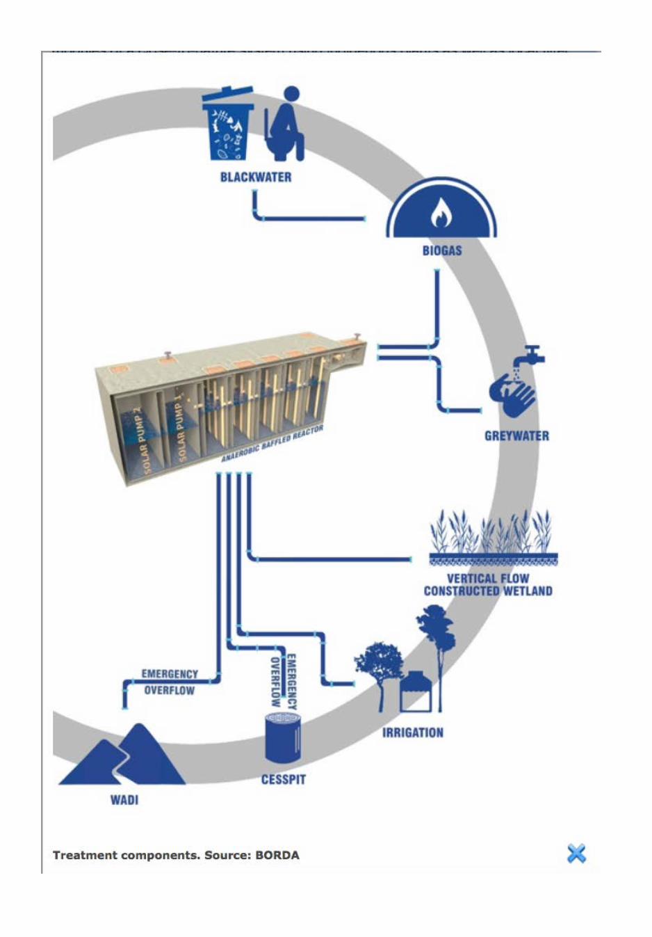
Overview on the treatment components
• Collection: connection of the kitchen WW to the blackwatersewer and connection of the treatment system to the existing separate blackwater and greywater sewers
• Blackwater treatment in a biogas settler (primary treatment)• Merging of the greywater (from existing sewer) and pretreated
blackwater (outlet of biogas settler) streams in a manhole• Anaerobic Baffled Reactor (ABR) (secondary treatment)• Distribution system with solar-pump, floating valve and
distribution chamber• Vertical-Flow Constructed Wetland (VFCW) (tertiary
treatment)• Recirculation of VFCW effluent to ABR for denitrification
process• Re-use: Biogas for cooking and treated wastewater for irrigation
of native trees.

Hydraulic flow in the system
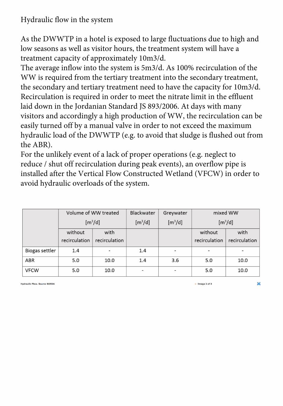
As the DWWTP in a hotel is exposed to large fluctuations due to high and low seasons as well as visitor hours, the treatment system will have a treatment capacity of approximately 10m3/d.The average inflow into the system is 5m3/d. As 100% recirculation of the WW is required from the tertiary treatment into the secondary treatment, the secondary and tertiary treatment need to have the capacity for 10m3/d. Recirculation is required in order to meet the nitrate limit in the effluent laid down in the Jordanian Standard JS 893/2006. At days with many visitors and accordingly a high production of WW, the recirculation can be easily turned off by a manual valve in order to not exceed the maximum hydraulic load of the DWWTP (e.g. to avoid that sludge is flushed out from the ABR).For the unlikely event of a lack of proper operations (e.g. neglect to reduce / shut off recirculation during peak events), an overflow pipe is installed after the Vertical Flow Constructed Wetland (VFCW) in order to avoid hydraulic overloads of the system.

Primary Treatment: Biogas Settler
Conceptual 3-D model of biogas digester in Feynan. Source: BORDA
Most close-to-nature DWWTP operate with its first chamber being a regular settler. For the application of the DWWTP at Feynan Ecolodge, the project decided for a biogas plant as it captures the methane gas exhaust, which is naturally produced by anaerobic WW treatment systems, and provides energy for part of the cooking demand. Furthermore, the system is set up in a way that all soft organic matter available in the lodge can be digested (co-fermented). This reduces disposal cost for solid waste.[For further information on biogas reactors, please refer to the previous page.]
Components:• Inlet: organic material (WW combined with solid waste such as
food residues, paper, card board boxes) fed into the digester.• Digester: (Underground) part of the system where the organic
material is exposed to methane-producing bacteria under anaerobic conditions.

• Outlet: Part of the system where the digested organic material(WW) is leaving the digester. During the digestion process methane gas is generated in the digester and due to the raising pressure in the digester the treated WW is pushed out of the digester.
• Expansion chamber/channel: Part of the system where thedigested organic material (WW) which is replaced by gas inside the digester is stored, exercising the pressure to push the gas out of the digester.
Secondary treatment: ABR

Anaerobic Baffle Reactors (ABR), also called Baffled Septic Tanks, are a combination of conventional septic tanks, fluidized bed reactors and an Up-flow Anaerobic Sludge Blanket (UASB) systems. Biological and natural chemical processes are used to degrade and therefore remove organic matter.Hence an ABR is an improved Septic Tank with a series of baffles under which WW is forced to flow under and over the baffles from the inlet to the outlet. Instead of using baffles it became recently more common to connect the chambers by vertical down-flow pipes that route the WW from the outlet of one chamber into the sludge layer that is accumulated at the bottom of the next chamber.The ABR consists of a series of chambers, in which the WW flows upstream. Pipes direct the WW stream between the individual chambers from top to bottom. At the bottom of each chamber, active sludge is retained. During inflow into the chamber, WW is forced to pass through the activated sludge blanked whereby it is inoculated with the WW organisms, which decompose the contained pollutants. The increased contact time with the active biomass (sludge) results in improved treatment. In the first chamber easily degradable substances are broken down while in the following chambers, decomposition of less degradable substances takes place.An equal distribution of fresh WW and a close contact between fresh influent and old active sludge are important process features. The WW flows upstream through each chamber with the effect that sludge particles settle against the up-stream of the water. This provides the possibility of intensive contact between sludge and newly incoming liquid.The WW flow between the chambers is directed by a parallel series of PVC-pipes which lead from the upper outlet of one chamber to the bottom of the following chamber; hence, the WW is directly exposed to the active sludge in the next chamber. The settled sludge must be removed in regular intervals; however, some sludge should always be left for continuous efficiency. In the first chambers, more sludge can be expected than in downstream chambers, which determines the time of removal. The last chamber can have a filter in its upper part to hold back possibly occurring solid particles.

The compartmentalized design separates the solids retention time from the hydraulic retention time, making it possible to anaerobically treat WW at short retention times of only some hours. Solids treatment rates are high, while the overall sludge production is characteristically low. They are simple to build and simple to operate, as well as very robust to hydraulic and organic shock loadingABR are robust and suitable for all kind of WW, including domestic. The systems are simple in construction and simple in operation. Its efficiency increases with higher organic load, as for all anaerobic processes. The treatment performance is in the range of 65% - 90% COD (70% - 95% BOD) removal. The pathogen reduction is in the range of 40-75%.
[For more information refer to the page on Anaerobic Baffled Reactor]
Components:• Mixing manhole: for greywater, pre-treated blackwater and
water from the recirculation• Distribution chamber: guarantees that the WW is entering the
system equally• ABR chambers: the WW will flow through PVC-pipes that are
connecting the 5 ABR-chambers. Between the ABR-chambers, the water flow is directed to the bottom of the next chamber by down-pipes that are placed at the partition walls. Through the distance between the pipes less than 50 cm, an equal distribution is guaranteed
• Solar pump 1: lifts the pre-treated wastewater up into thedistribution chamber
• Solar pump 2: recirculates the WW partly into the ABR fornitrate removal and partly pumps the treated WW to a storage tank for further irrigation of native plants

Tertiary treatment: Vertical Flow Constructed Wetland
The VFCW is used as tertiary treatment step for Nitrification, SS (Suspended Solids) removal and partly disinfection. The biological VFCW treatment step combines aerobic and anaerobic decomposition processes in a substratum layer. The polyethylene or PVC lined and refilled basins are planted with sewage adapted helophytes (Phragmites australis).The wastewater percolates the filter substrate vertically to the bottom drains. Through the microbial and fungal decomposition of organic matter and pollutants in the rooted substrate matrix, organic matter and pollutants can be efficiently removed. A variety of sub-surface micro-habitats differing oxygenation and redox potential support a diversity of microorganisms – bacteria, fungi, actinomycetes, protozoa – which degrade organic and inorganic substrates entering the system. In addition, chemical and physical precipitation, adsorption and filter processes occur. In addition, important phosphate and ammonia binding processes can take place and some of the wastewater nitrogen is released out of the artificial ecosystem as nitrogenous gases (denitrification).

A strong root penetration of the vegetation transfers oxygen to the filter zone, improves the soil structure and increases the performance of the microbes located within the root system. Another part of oxygen transfer into the rhizosphere happens through a special helophyte tissue in the plant stems and roots (aerenchym) from the air. In addition, the arid climate with its high temperatures encourages the plant growth and oxygen supply through improved photosynthesis processes. CW typically have limited oxygen availability to trigger nitrification and denitrification for nitrogen removal from ammonium-rich wastewater. Through intermittent loading of the VFCWs a radical change of oxygen regime is achieved. After water saturation by feeding with the distribution system, a drainage network at the base collects the purified water. The pore space of the substrate is refilled with air thus enabling aerobic decomposition processes. Another part of oxygen transfer into the rhizosphere happens through a special helophyte tissue in the plant stems and roots (aerenchym) from the air. The reduction of nitrate to nitrogen gas through denitrification takes place under anoxic conditions. Thus, a carbon source in the wastewater is required. Recirculation after the treatment in the VFCW into the pre-treatment unit can be considered as a suitable solution for nitrogen removal. As in the ABR-module still a lot of particles with Chemical Oxygen Demand are available, recirculation into the ABR-inlet is recommended. Clogging effects of the filter substrates are prevented by the continuous growth and decay of roots and rhizomes of the aquatic macrophytes and the thereby remaining soil macropores. In this manner, long-term water transport into the soil matrix is guaranteed. No additional filtration is required.In conclusion, the VFCW functions as tertiary treatment step for nitrification, suspended solid removal and partly disinfection for further reuse of the treated wastewater.[For further information refer to the page on Vertical Flow Constructed Wetland]
Components:• Solar Pump 1: the outflow from the ABR is transferred by a solar
pump system into the floating valve chamber. • Floating Valve and Distribution Chamber: The pre-treated
sewage is pumped from solar pump 1 and discharged into the 2 VFCW basins via a floating valve chamber with a wet volume of 2 m³/batch. With a wet volume of 2 m³ the daily hydraulic load on the VFCW (5 m³ from lodge + 5 m³ recirculation) is split into 5 batches. From the floating valve chamber the water flows through a distribution chamber to the 2 reed bed basins.
• Reed Bed: Both reed bed basins are under operation parallel, onlyfor maintenance the flow to one of the basins can be stopped with the help of a stop-pipe in the distribution chamber. One basin can also be taken out of operation after a period of overload of the system by organics or solids.
• Water Collection Chamber: the drain water from the VFCW iscollected in a chamber and partly recirculated to the inflow of the ABR and partly pumped to the irrigation storage tank with help of a second solar pump. The design allows for a 100% recirculation by the solar pump (5 m³/day).
• Pipes: two different kind of pipes are required within the reedbed: 1. Distribution pipes: guarantee the distribution of the pretreated wastewater through holes in the distribution pipes equally to the basins, and 2. Drainage pipes: drain the treated wastewater into the water collection chamber for reuse and recirculation
• Filter Material: The bottom layer of filter material covers thedrainage pipes and protects these pipes from the finer major filter layer. This layer is either natural fine gravel or crushed material (5 – 10 mm, 3/8”). The Terzaghi filter rule must be applied to the gravel. Once the filter sand is chosen, the gravel can be calculated according to D15/d15 ≥ 4 and D15 / d85 ≤ 4. The filter sand must be double washed sand 0-4 mm, kf 10^-4 m/s, U < 5 and 0.2 mm < d10 < 0.4mm.
• Reed plants: The VFCW will be planted with reed plants(Phragmites Australis) of 5 pcs per m². There is a similar plant widely spread in Jordan wadis, Arundo Donax, this plant does not have such a strong and deep growing rhizome system and should therefore not be used in VFCW.


The objective is to pilot a small-scale DWWTP with the capacity of 50 m3/d and a reuse-system. The treatment system will be constructed within the premises of the existing WWTP Wadi Hassan, that is owned by the WAJ and operated by YWC.Hence, part of the inlet for the existing treatment facility will be diverted and treated within the small-scale treatment unit in order to demonstrate suitable treatment modules for DWWM. The effluent of the DWWTP will be partly merged with the outflow from the existing centralized WWTP and partly reused for irrigation on-site. The treated effluent of Wadi Hassan central WWTP provides two nearby farms and the Jordan University of Science and Technology (JUST) with water for irrigation on a large-scale for agriculture (pistachio, almonds and olive trees). The DWWTP project constitutes a sustainable low-maintenance and low-tech solution incorporating different modules of a close-to-nature system using indigenous plants as well as local filter materials.The system will ensure to reach the local effluent requirements (Jordanian Standard 893/2006) for a safe reuse of the treated WW and will serve as a demonstration unit for DWWT in Jordan showing the combination of anaerobic treatment with a wetland system.

Overview on the treatment components

• Diversion module including pre-treatment (screen, gritchamber and pump shaft) from the main sewer system
• Settler Tank (primary treatment)• Anaerobic Baffled Reactor (ABR) (secondary treatment)• Siphon and distribution chamber for the VFCW• Vertical-Flow Constructed Wetland (VFCW) (tertiary
treatment)• Solar pump chamber installed to recirculate the effluent
of the VFCW to the pump shaft inlet in the pretreatment phase which is required for the denitrification process to comply with the Jordanian effluent standards (JS 893/2006).
• As 100% recirculation of the WW is required from theVFCW outlet into the pump shaft to ensure denitrification, the primary, secondary and tertiary treatment modules need to have a capacity of 100 m3/d although only 50m3/d raw WW are treated
• Reuse: the effluent of the DWWTP will be partly mergedwith the outflow from the existing centralized WWTP and partly reused for irrigation on-site
Hydraulic flow in the system
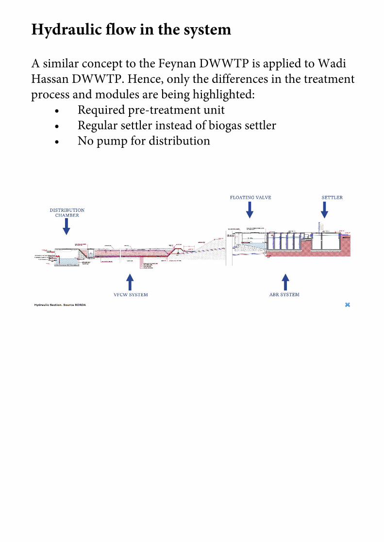
A similar concept to the Feynan DWWTP is applied to Wadi Hassan DWWTP. Hence, only the differences in the treatment process and modules are being highlighted:
• Required pre-treatment unit• Regular settler instead of biogas settler• No pump for distribution

Pre-treatment: Screen, grit chamber and pump shaft
Components:• Screen: Screening aims to prevent coarse solids, such as
plastics, rags and other trash, from entering into the treatment plant. Solids get trapped by inclined bar screens. The spacing between the bars in Wadi Hassan is 50 mm.
• Grit chamber: the grit chamber in Wadi Hassan is requiredto prevent damage and blockage to the submersed pump in the following pump shaft in order to protect the subsequent treatment technologies. The presence of the grit chambers allows for the removal of heavy inorganic fractions by settling. The horizontal grit chamber allows heavy grit particles to settle out, while lighter, principally organic particles remain in suspension.
• Pump shaft: in order to regulate a steady inflow of 50 m3/dfrom the main sewer line into the DWWTP, a pump including a pump shaft is required.

Primary Treatment: Settler
Components:The first compartment occupies about two-thirds of the septic-tank volume, allowing most of the sludge and scum accumulation. The following chamber serves to calm the turbulent liquid. The following aspects should be considered for the design of a settler:
• All chambers are normally the same depth. The firstchamber is sometimes deeper.
• The size of the first chamber is calculated to be at leasttwice the accumulating sludge volume. The sludge volume depends on the settleable solids content of the influent and on desludging intervals.

The compartments are connected by simple wall openings located above the highest sludge level and below the lowest level of the scum. For domestic WW, the top of the opening should be 30cm below outlet level, its base at least half the water depth above the floor. The openings should be equally distributed across the width of the tank, to minimize turbulence. A slot, spanning the full width of the tank, is ideal for reducing velocity and turbulence.
• The outlet has a T-joint, the lower arm of which dives30cm below the water level. With this design, foul gas trapped in the tank enters the sewage line from where it must be ventilated safely. If ventilation cannot be guaranteed, an elbow must to be used at the outlet to prevent the gas from entering the outlet pipe. There should be manholes in the cover slab; one each above inlet and outlet and one at each baffle wall, preferably at the inlet of each compartment.
• The treatment efficiency of a settler ranges from 25%to 50% COD removal. It serves as rough, primary treatment, prior to secondary and tertiary treatment. The settler is integrated as the first section of the ABR. [For further information refer to the page «Settler»]

Secondary treatment: ABR
Logitudinal section and top view (below) of the ABR in Wadi Hassan. Source: BORDAThe ABR is already described in the case study on the Feynan Ecolodge, where the Anaerobic Baffled Reactor is also used for secondary treatment.Components:
• are described in the images on the right and below.[For more information refer to the page on Anaerobic Baffled Reactor]

Tertiary treatment: Vertical Flow Constructed Wetland
The VFCW is already described in the case study on the Feynan Ecolodge, where the it is also used for tertiary treatment processes.In comparison to the Feynan Ecolodge, there is no pump needed for distribution: A VFCW has to be fed regularly with WW in batches. The distribution system of the VFCW is ideally designed to receive 5 batches with a minimum time difference of 2 hours.In this regard, the distribution through a floating valve seems to be a suitable solution in the context of Wadi Hassan to avoid using electricity to run a pump. Nevertheless, a floating valve requires suitable topographic conditions – slope in order to guarantee an even distribution over the VFCW surface area. In Wadi Hassan (compared to Feynan) the slope is given and hence, electricity for pumping can be avoided. The floating valve provides intermittent batches into the VFCW system.
[For more information refer also to the page on Vertical Flow Constructed Wetland (VFCW)]

Components:
• are also described in the images below. Additional components (compared to the VFCW used in Feynan Ecolodge) are • 4 Reed Basins: the 4 reed bed basins are under operation in parallel, only for maintenance the flow to one of the basins can be stopped with the help of a stop-pipe in the distribution chamber. One basin can also be taken out of operation after a period of overload of the system by organics or solids. • Spray Nozzles: for a better distribution over the basin subsurface `Low Pressure Swirl Nozzles` distribute the water vertically and horizontally to the basin. One nozzle every 4 m will cover around 12 m2 surface of the VFCW basin, hence 125 nozzles are needed for the 4 VFCW basins. The Low-Pressure Swirl Nozzles will be installed simply in front of pre-drilled holes in the pipes with cable ties (black, UV-stabilized). The purpose of the nozzles is to maintain the pressure within the piping system and guarantee an equal distribution over the whole surface of the VFCW. The alternative to the nozzles would be wholes within the pipping system. Due to a lack of pressure towards the end of the distribution pipe with only holes within the pipes and without nozzles, the WW would be flooded within the first part of the basin and dry within the other parts of the basins especially because of the relevant size of basins.


Waste Stabilization Pond
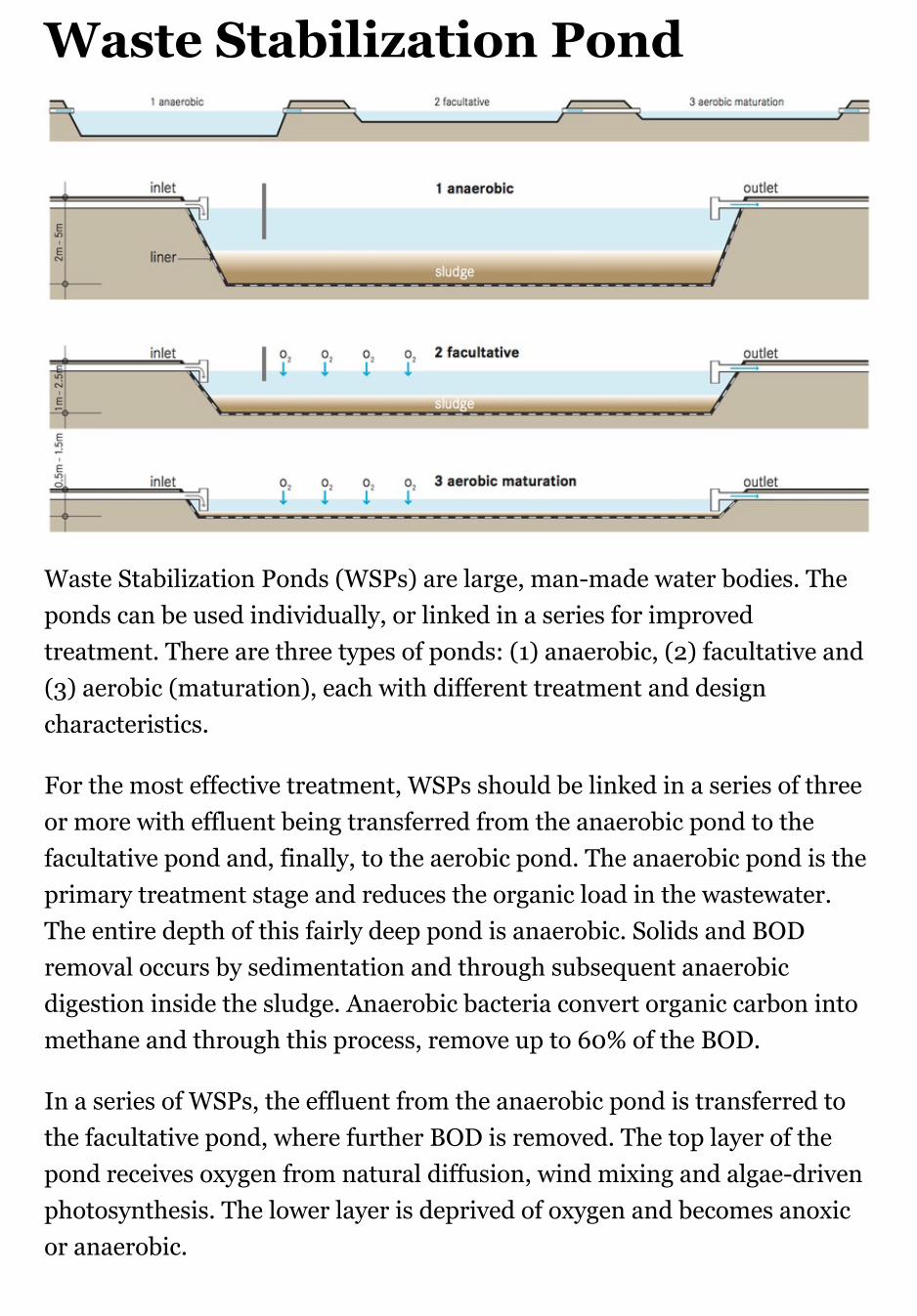
Waste Stabilization Ponds (WSPs) are large, man-made water bodies. Theponds can be used individually, or linked in a series for improvedtreatment. There are three types of ponds: (1) anaerobic, (2) facultative and(3) aerobic (maturation), each with different treatment and designcharacteristics.
For the most effective treatment, WSPs should be linked in a series of threeor more with effluent being transferred from the anaerobic pond to thefacultative pond and, finally, to the aerobic pond. The anaerobic pond is theprimary treatment stage and reduces the organic load in the wastewater.The entire depth of this fairly deep pond is anaerobic. Solids and BODremoval occurs by sedimentation and through subsequent anaerobicdigestion inside the sludge. Anaerobic bacteria convert organic carbon intomethane and through this process, remove up to 60% of the BOD.
In a series of WSPs, the effluent from the anaerobic pond is transferred tothe facultative pond, where further BOD is removed. The top layer of thepond receives oxygen from natural diffusion, wind mixing and algae-drivenphotosynthesis. The lower layer is deprived of oxygen and becomes anoxicor anaerobic.

Settleable solids accumulate and are digested on the bottom of the pond.The aerobic and anaerobic organisms work together to achieve BODreductions of up to 75%. Anaerobic and facultative ponds are designed forBOD removal, while aerobic ponds are designed for pathogen removal. Anaerobic pond is commonly referred to as a maturation, polishing, orfinishing pond because it is usually the last step in a series of ponds andprovides the final level of treatment. It is the shallowest of the ponds,ensuring that sunlight penetrates the full depth for photosynthesis to occur.Photosynthetic algae release oxygen into the water and at the same timeconsume carbon dioxide produced by the respiration of bacteria.
Because photosynthesis is driven by sunlight, the dissolved oxygen levelsare highest during the day and drop off at night. Dissolved oxygen is alsoprovided by natural wind mixing.
Design Considerations
Anaerobic ponds are built to a depth of 2 to 5 m and have a relatively shortdetention time of 1 to 7 days. Facultative ponds should be constructed to adepth of 1 to 2.5 m and have a detention time between 5 to 30 days. Aerobicponds are usually between 0.5 to 1.5 m deep.
If used in combination with algae and/or fish harvesting, this type of pondis effective at removing the majority of nitrogen and phosphorus from theeffluent. Ideally, several aerobic ponds can be built in series to provide ahigh level of pathogen removal.
Pre-treatment is essential to prevent scum formation and to hinder excesssolids and garbage from entering the ponds. To prevent leaching into thegroundwater, the ponds should have a liner. The liner can be made fromclay, asphalt, compacted earth, or any other impervious material. To protectthe pond from runoff and erosion, a protective berm should be constructedaround the pond using the excavated material.
A fence should be installed to ensure that people and animals stay out of thearea and that garbage does not enter the ponds.
Appropriateness

WSPs are among the most common and efficient methods of wastewatertreatment around the world. They are especially appropriate for rural andperi-urban communities that have large, unused land, at a distance fromhomes and public spaces. They are not appropriate for very dense or urbanareas.
Health Aspects & Acceptance
Although effluent from aerobic ponds is generally low in pathogens, theponds should in no way be used for recreation or as a direct source of waterfor consumption or domestic use.
Operation & Maintenance
Scum that builds up on the pond surface should be regularly removed.Aquatic plants (macrophytes) that are present in the pond should also beremoved as they may provide a breeding habitat for mosquitoes and preventlight from penetrating the water column.
The anaerobic pond must be desludged approximately once every 2 to 5years, when the accumulated solids reach one third of the pond volume. Forfacultative ponds sludge removal is even rarer and maturation ponds hardlyever need desludging. Sludge can be removed by using a raft-mountedsludge pump, a mechanical scraper at the bottom of the pond or by drainingand dewatering the pond and removing the sludge with a front-end loader.

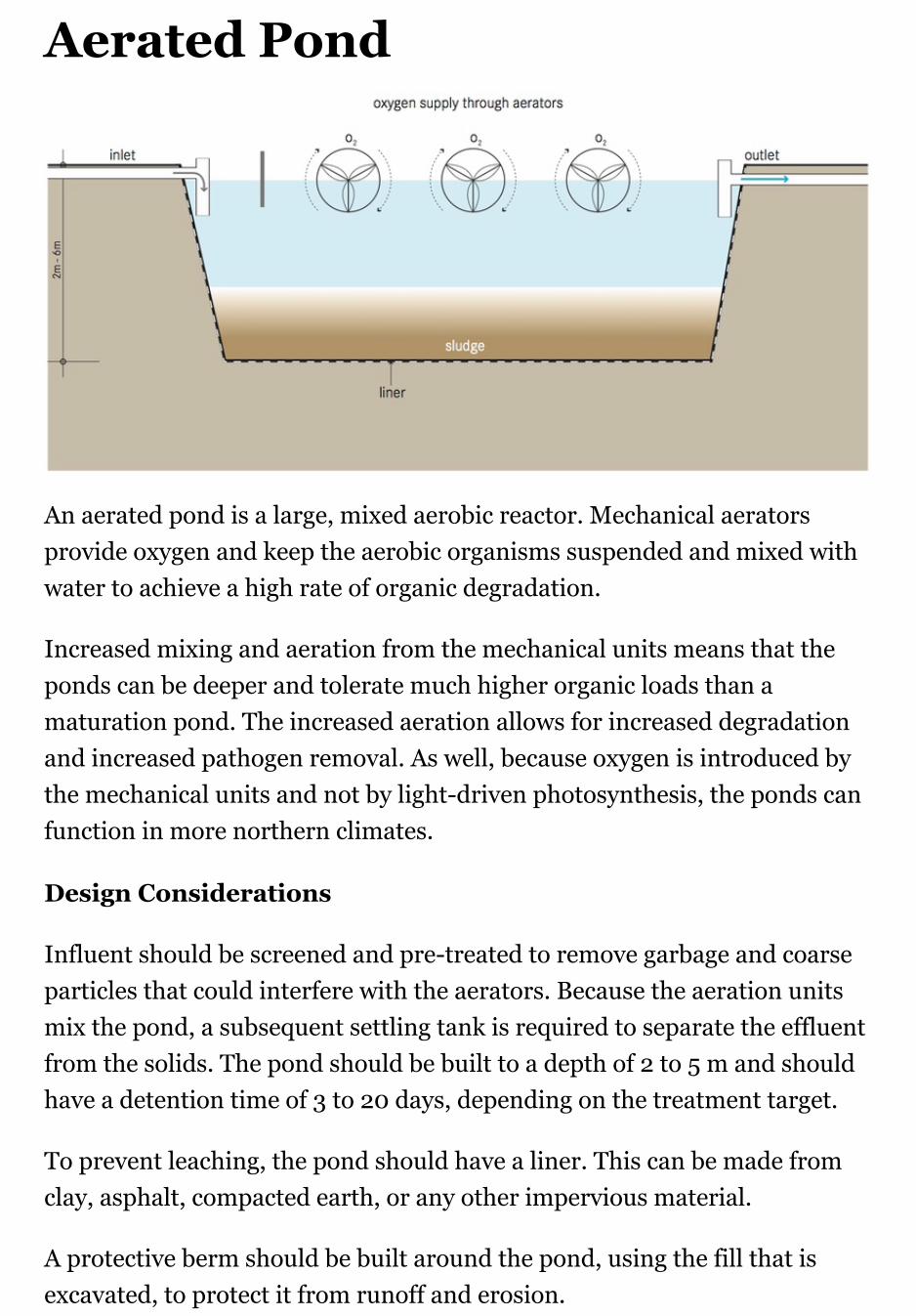
Aerated Pond
An aerated pond is a large, mixed aerobic reactor. Mechanical aeratorsprovide oxygen and keep the aerobic organisms suspended and mixed withwater to achieve a high rate of organic degradation.
Increased mixing and aeration from the mechanical units means that theponds can be deeper and tolerate much higher organic loads than amaturation pond. The increased aeration allows for increased degradationand increased pathogen removal. As well, because oxygen is introduced bythe mechanical units and not by light-driven photosynthesis, the ponds canfunction in more northern climates.
Design Considerations
Influent should be screened and pre-treated to remove garbage and coarseparticles that could interfere with the aerators. Because the aeration unitsmix the pond, a subsequent settling tank is required to separate the effluentfrom the solids. The pond should be built to a depth of 2 to 5 m and shouldhave a detention time of 3 to 20 days, depending on the treatment target.
To prevent leaching, the pond should have a liner. This can be made fromclay, asphalt, compacted earth, or any other impervious material.
A protective berm should be built around the pond, using the fill that isexcavated, to protect it from runoff and erosion.
Appropriateness
A mechanically aerated pond can efficiently handle concentrated influentand significantly reduce pathogen levels. It is especially important thatelectricity service is uninterrupted and that replacement parts are availableto prevent extended downtimes that may cause the pond to turn anaerobic.
Aerated ponds can be used in both rural and peri-urban environments.They are most appropriate for regions with large areas of inexpensive landlocated away from homes and businesses. Aerated lagoons can function in alarger range of climates than Waste Stabilization Ponds and the arearequirement is smaller compared to a maturation pond.
Health Aspects & Acceptance
The pond is a large expanse of pathogenic wastewater; care must be takento ensure that no one comes in contact with or goes into the water.
The aeration units can be dangerous to humans and animals. Fences,signage, or other measures should be taken to prevent entry into the area.
Operation & Maintenance
Permanent, skilled staff is required to maintain and repair aerationmachinery and the pond must be desludged every 2 to 5 years.
Care should be taken to ensure that the pond is not used as a garbage dump,especially considering the damage that could result to the aerationequipment.


Horizontal Subsurface FlowConstructed Wetland
A horizontal subsurface flow constructed wetland is a large gravel and sand-filled basin that is planted with wetland vegetation. As wastewater flowshorizontally through the basin, the filter material filters out particles andmicroorganisms degrade the organics.
The filter media acts as a filter for removing solids, a fixed surface uponwhich bacteria can attach, and a base for the vegetation. Althoughfacultative and anaerobic bacteria degrade most organics, the vegetationtransfers a small amount of oxygen to the root zone so that aerobic bacteriacan colonize the area and degrade organics as well. The plant roots play animportant role in maintaining the permeability of the filter.
Design Considerations
The design of a horizontal subsurface flow constructed wetland depends onthe treatment target and the amount and quality of the influent. It includesdecisions about the amount of parallel flow paths and compartmentation.The removal efficiency of the wetland is a function of the surface area(length multiplied by width), while the cross-sectional area (widthmultiplied by depth) determines thema ximum possible flow.
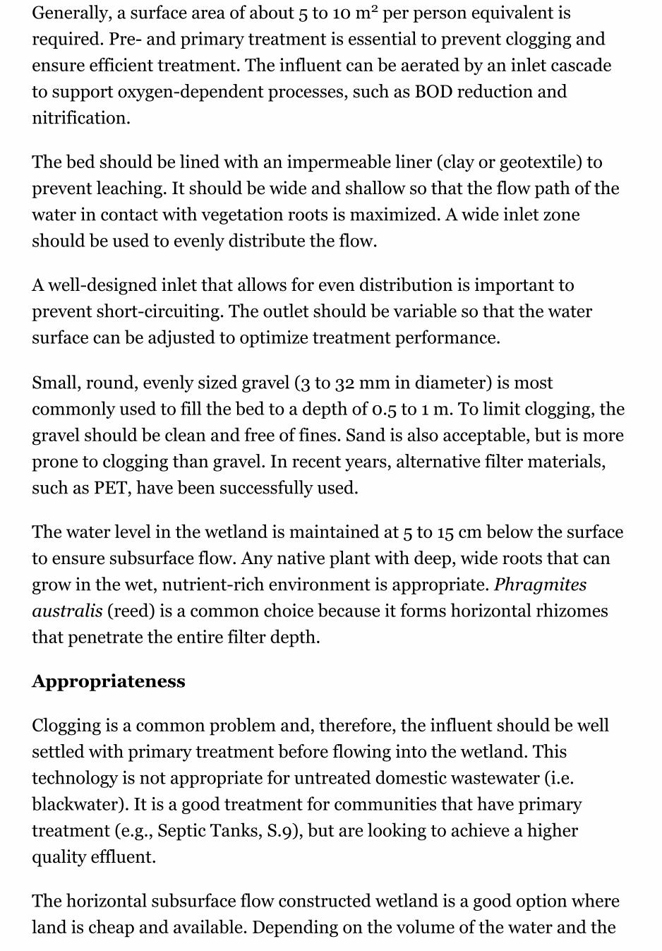
Generally, a surface area of about 5 to 10 m2 per person equivalent isrequired. Pre- and primary treatment is essential to prevent clogging andensure efficient treatment. The influent can be aerated by an inlet cascadeto support oxygen-dependent processes, such as BOD reduction andnitrification.
The bed should be lined with an impermeable liner (clay or geotextile) toprevent leaching. It should be wide and shallow so that the flow path of thewater in contact with vegetation roots is maximized. A wide inlet zoneshould be used to evenly distribute the flow.
A well-designed inlet that allows for even distribution is important toprevent short-circuiting. The outlet should be variable so that the watersurface can be adjusted to optimize treatment performance.
Small, round, evenly sized gravel (3 to 32 mm in diameter) is mostcommonly used to fill the bed to a depth of 0.5 to 1 m. To limit clogging, thegravel should be clean and free of fines. Sand is also acceptable, but is moreprone to clogging than gravel. In recent years, alternative filter materials,such as PET, have been successfully used.
The water level in the wetland is maintained at 5 to 15 cm below the surfaceto ensure subsurface flow. Any native plant with deep, wide roots that cangrow in the wet, nutrient-rich environment is appropriate. Phragmitesaustralis (reed) is a common choice because it forms horizontal rhizomesthat penetrate the entire filter depth.
Appropriateness
Clogging is a common problem and, therefore, the influent should be wellsettled with primary treatment before flowing into the wetland. Thistechnology is not appropriate for untreated domestic wastewater (i.e.blackwater). It is a good treatment for communities that have primarytreatment (e.g., Septic Tanks, S.9), but are looking to achieve a higherquality effluent.
The horizontal subsurface flow constructed wetland is a good option whereland is cheap and available. Depending on the volume of the water and the
corresponding area requirement of the wetland, it can be appropriate forsmall sections of urban areas, as well as for peri-urban and ruralcommunities. It can also be designed for single households.
This technology is best suited for warm climates, but it can be designed totolerate some freezing and periods of low biological activity. If the effluentis to be reused, the losses due to high evapotranspiration rates could be adrawback of this technology, depending on the climate.
Health Aspects & Acceptance
Significant pathogen removal is accomplished by natural decay, predationby higher organisms, and filtration. As the water flows below the surface,any contact of pathogenic organisms with humans and wildlife isminimized.
The risk of mosquito breeding is reduced since there is no standing watercompared to the risk associated with Free-Water Surface ConstructedWetlands. The wetland is aesthetically pleasing and can be integrated intowild areas or parklands.
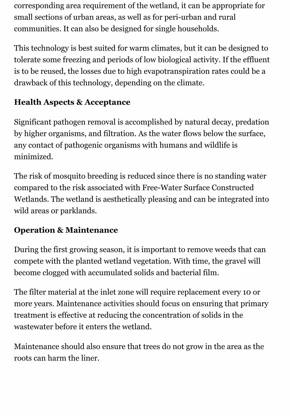
Operation & Maintenance
During the first growing season, it is important to remove weeds that cancompete with the planted wetland vegetation. With time, the gravel willbecome clogged with accumulated solids and bacterial film.
The filter material at the inlet zone will require replacement every 10 ormore years. Maintenance activities should focus on ensuring that primarytreatment is effective at reducing the concentration of solids in thewastewater before it enters the wetland.
Maintenance should also ensure that trees do not grow in the area as theroots can harm the liner.


Trickling FilterA trickling filter is a fixed-bed, biological reactor that operates under(mostly) aerobic conditions. Pre-settled wastewater is continuously‘trickled’ or sprayed over the filter. As the water migrates through the poresof the filter, organics are degraded by the biofilm covering the filtermaterial.
The trickling filter is filled with a high specific surface area material, such asrocks, gravel, shredded PVC bottles, or special pre-formed plastic filtermedia. A high specific surface provides a large area for biofilm formation.Organisms that grow in the thin biofilm over the surface of the mediaoxidize the organic load in the wastewater to carbon dioxide and water,while generating new biomass.
The incoming pre-treated wastewater is ‘trickled’ over the filter, e.g., withthe use of a rotating sprinkler. In this way, the filter media goes throughcycles of being dosed and exposed to air. However, oxygen is depletedwithin the biomass and the inner layers may be anoxic or anaerobic.
Design Considerations
The filter is usually 1 to 2.5 m deep, but filters packed with lighter plasticfilling can be up to 12 m deep. The ideal filter material is low-cost anddurable, has a high surface to volume ratio, is light, and allows air tocirculate.
Whenever it is available, crushed rock or gravel is the cheapest option. Theparticles should be uniform and 95% of them should have a diameterbetween 7 and 10 cm. A material with a specific surface area between 45 and60 m2/m3 for rocks and 90 to 150 m2/m3 for plastic packing is normallyused. Larger pores (as in plastic packing) are less prone to clogging andprovide for good air circulation. Primary treatment is also essential toprevent clogging and to ensure efficient treatment.
Adequate air flow is important to ensure sufficient treatment performanceand prevent odours. The underdrains should provide a passageway for air at

the maximum filling rate. A perforated slab supports the bottom of thefilter, allowing the effluent and excess sludge to be collected.
The trickling filter is usually designed with a recirculation pattern for theeffluent to improve wetting and flushing of the filter material.
With time, the biomass will grow thick and the attached layer will bedeprived of oxygen; it will enter an endogenous state, will lose its ability tostay attached and will slough off. High-rate loading conditions will alsocause sloughing. The collected effluent should be clarified in a settling tankto remove any biomass that may have dislodged from the filter.
The hydraulic and nutrient loading rate (i.e., how much wastewater can beapplied to the filter) is determined based on the characteristics of thewastewater, the type of filter media, the ambient temperature, and thedischarge requirements.
Appropriateness
This technology can only be used following primary clarification since highsolids loading will cause the filter to clog.
A low-energy (gravity) trickling system can be designed, but in general, acontinu-us supply of power and wastewater is required. Compared to othertechnologies (e.g., Waste Stabilization Ponds), trickling filters are compact,although they are still best suited for peri-urban or large, rural settlements.
Trickling filters can be built in almost all environments, but specialadaptations for cold climates are required.
Health Aspects & Acceptance
Odour and fly problems require that the filter be built away from homes andbusinesses.
Appropriate measures must be taken for pre- and primary treatment,effluent discharge and solids treatment, all of which can still pose healthrisks.

Operation & Maintenance
A skilled operator is required to monitor the filter and repair the pump incase of problems. The sludge that accumulates on the filter must beperiodically washed away to prevent clogging and keep the biofilm thin andaerobic. High hydraulic loading rates (flushing doses) can be used to flushthe filter. Optimum dosing rates and flushing frequency should bedetermined from the field operation.
The packing must be kept moist. This may be problematic at night when thewater flow is reduced or when there are power failures.
Snails grazing on the biofilm and filter flies are well known problemsassociated with trickling filters and must be handled by backwashing andperiodic flooding.


Upflow Anaerobic SludgeBlanket Reactor (UASB)
The upflow anaerobic sludge blanket reactor (UASB) is a single tankprocess. Wastewater enters the reactor from the bottom, and flows upward.A suspended sludge blanket filters and treats the wastewater as thewastewater flows through it.
The sludge blanket is comprised of microbial granules (1 to 3 mm indiameter), i.e., small agglomerations of microorganisms that, because oftheir weight, resist being washed out in the upflow. The microorganisms inthe sludge layer degrade organic compounds. As a result, gases (methaneand carbon dioxide) are released. The rising bubbles mix the sludge withoutthe assistance of any mechanical parts. Sloped walls deflect material thatreaches the top of the tank downwards. The clarified effluent is extractedfrom the top of the tank in an area above the sloped walls.
After several weeks of use, larger granules of sludge form which, in turn, actas filters for smaller particles as the effluent rises through the cushion ofsludge. Because of the upflow regime, granule-forming organisms arepreferentially accumulated as the others are washed out.

Design Considerations
Critical elements for the design of UASB reactors are the influentdistribution system, the gas-solids separator, and the effluent withdrawaldesign. The gas that rises to the top is collected in a gas collection dome andcan be used as energy (biogas).
An upflow velocity of 0.7 to 1 m/h must be maintained to keep the sludgeblanket in suspension. Primary settling is usually not required before theUASB.
Appropriateness
A UASB is not appropriate for small or rural communities without aconstant water supply or electricity. The technology is relatively simple todesign and build, but developing the granulated sludge may take severalmonths.
The UASB reactor has the potential to produce higher quality effluent thanSeptic Tanks (S.9), and can do so in a smaller reactor volume. Although it isa well-established process for large-scale industrial wastewater treatmentand high organic loading rates up to 10 kg BOD/m3/d, its application todomestic sewage is still relatively new.
It is often used for brewery, distillery, food processing and pulp and paperwaste since the process typically removes 80 to 90% of COD. Where theinfluent is low-strength or where it contains too many solids, proteins orfats, the reactor may not work properly.
Temperature is also a key factor affecting the performance.
Health Aspects & Acceptance
The operators should take proper health and safety measures while workingin the plant, such as adequate protective clothing.
Effluent and sludge still pose a health risk and should not be directlyhandled.
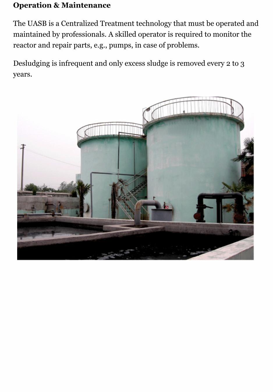
Operation & Maintenance
The UASB is a Centralized Treatment technology that must be operated andmaintained by professionals. A skilled operator is required to monitor thereactor and repair parts, e.g., pumps, in case of problems.
Desludging is infrequent and only excess sludge is removed every 2 to 3years.


Activated Sludge / SequencingBatch Reactor
An activated sludge process refers to a multi-chamber reactor unit thatmakes use of highly concentrated microorganisms to degrade organics andremove nutrients from wastewater to produce a high-quality effluent. Tomaintain aerobic conditions and to keep the activated sludge suspended, acontinuous and well-timed supply of oxygen is required.
Different configurations of the activated sludge process can be employed toensure that the wastewater is mixed and aerated in an aeration tank.Aeration and mixing can be provided by pumping air or oxygen into thetank or by using surface aerators. The microorganisms oxidize the organiccarbon in the wastewater to produce new cells, carbon dioxide and water.Although aerobic bacteria are the most common organisms, facultativebacteria along with higher organisms can be present. The exact compositiondepends on the reactor design, environment, and wastewatercharacteristics.
The flocs (agglomerations of sludge particles), which form in the aeratedtank, can be removed in the secondary clarifier by gravity settling. Some ofthis sludge is recycled from the clarifier back to the reactor. The effluent can
be discharged into a river or treated in a tertiary treatment facility ifnecessary for further use.
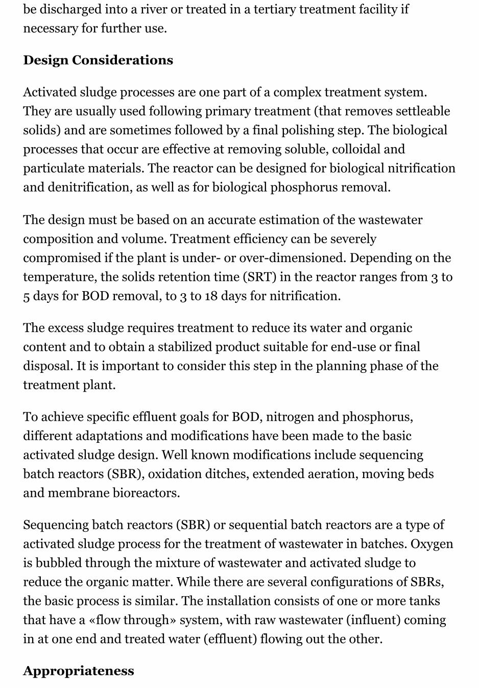
Design Considerations
Activated sludge processes are one part of a complex treatment system.They are usually used following primary treatment (that removes settleablesolids) and are sometimes followed by a final polishing step. The biologicalprocesses that occur are effective at removing soluble, colloidal andparticulate materials. The reactor can be designed for biological nitrificationand denitrification, as well as for biological phosphorus removal.
The design must be based on an accurate estimation of the wastewatercomposition and volume. Treatment efficiency can be severelycompromised if the plant is under- or over-dimensioned. Depending on thetemperature, the solids retention time (SRT) in the reactor ranges from 3 to5 days for BOD removal, to 3 to 18 days for nitrification.
The excess sludge requires treatment to reduce its water and organiccontent and to obtain a stabilized product suitable for end-use or finaldisposal. It is important to consider this step in the planning phase of thetreatment plant.
To achieve specific effluent goals for BOD, nitrogen and phosphorus,different adaptations and modifications have been made to the basicactivated sludge design. Well known modifications include sequencingbatch reactors (SBR), oxidation ditches, extended aeration, moving bedsand membrane bioreactors.
Sequencing batch reactors (SBR) or sequential batch reactors are a type ofactivated sludge process for the treatment of wastewater in batches. Oxygenis bubbled through the mixture of wastewater and activated sludge toreduce the organic matter. While there are several configurations of SBRs,the basic process is similar. The installation consists of one or more tanksthat have a «flow through» system, with raw wastewater (influent) comingin at one end and treated water (effluent) flowing out the other.
Appropriateness

An activated sludge process is only appropriate for a Centralized Treatmentfacility with a well-trained staff, constant electricity and a highly developedmanagement system that ensures that the facility is correctly operated andmaintained.Because of economies of scale and less fluctuating influentcharacteristics, this technology is more effective for the treatment of largevolumes of flows.
An activated sludge process is appropriate in almost every climate.However, treatment capacity is reduced in colder environments.
Health Aspects & Acceptance
Because of space requirements and odours, Centralized Treatment facilitiesare generally located in the periphery of densely populated areas.
Although the effluent produced is of high quality, it still poses a health riskand should not be directly handled. In the excess sludge pathogens aresubstantially reduced, but not eliminated.
Operation & Maintenance
Highly trained staff is required for maintenance and trouble-shooting. Themechanical equipment (mixers, aerators and pumps) must be constantlymaintained.
As well, the influent and effluent must be constantly monitored and thecontrol parameters adjusted, if necessary, to avoid abnormalities that couldkill the active biomass and the development of detrimental organisms whichcould impair the process (e.g., filamentous bacteria).
In the SBR, aeration times vary according to the plant size and thecomposition/quantity of the incoming wastewater, but are typically 60 to90 minutes. The addition of oxygen encourages the multiplication ofaerobic bacteria and they consume the nutrients. The settling stage isusually the same length in time as the aeration. During this stage the sludgeformed by the bacteria is allowed to settle to the bottom of the tank. Theaerobic bacteria continue to multiply until the dissolved oxygen is all butused up.

Conditions in the tank, especially near the bottom are now more suitable forthe anaerobic bacteria to flourish. The sludge within the tank increases overtime and a waste activated sludge pump removes some of the sludge duringthe settle stage to a digester for further treatment. The quantity or «age» ofsludge within the tank is closely monitored, as this can have a marked effecton the treatment process.


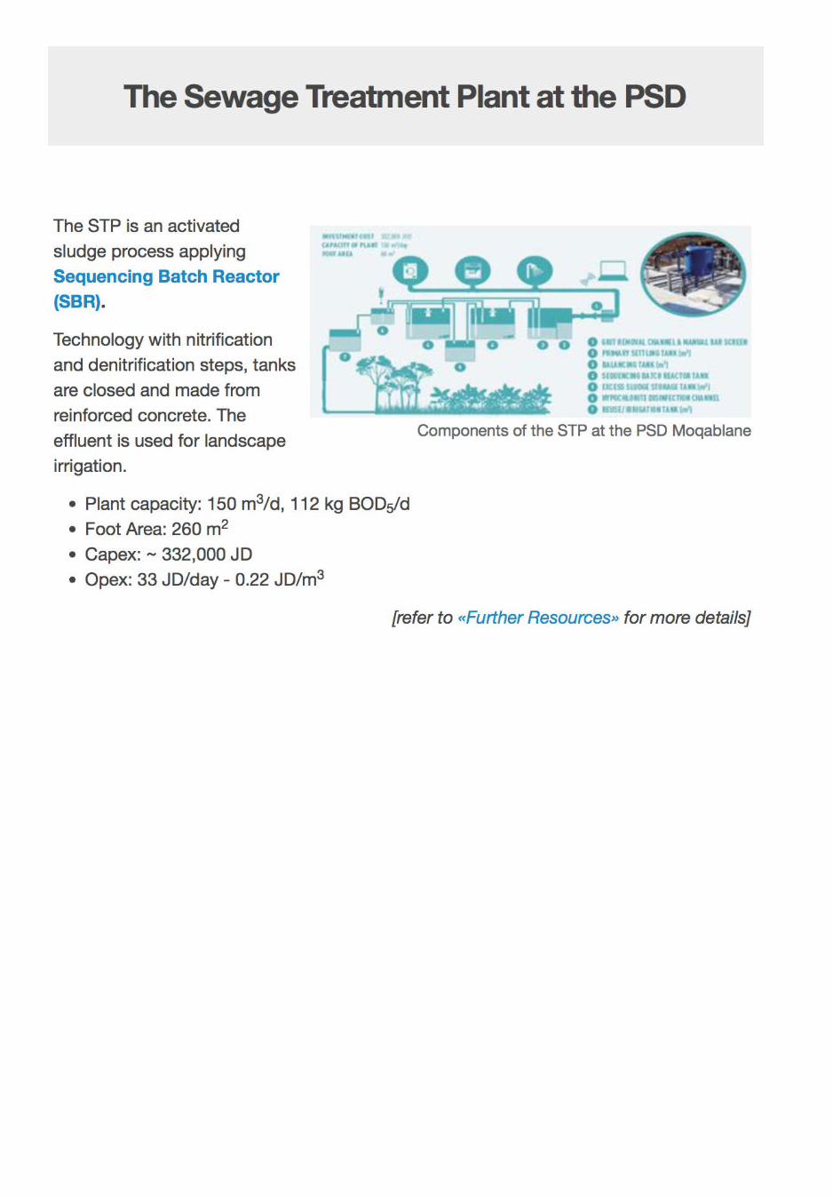
In this final lesson, the Decentralized Sewage Treatment Plant (STP) at the Public Security Directorate (PSD) in Moqablane, Amman is introduced. The three pillars (social, environmental, economic) on which «Sustainability» bases are mentioned and methods how it can be assessed are discussed. The lesson (and this first course) is finished with an exercise in which you will have the opportunity to assess the sustainability criteria for this STP.
The PSD compound is located in an urban area of Amman with residential, commercial and administrative buildings. It comprises an area of 150,000 m2, whereof ca. 12% is currently used as green areas. Additionally 10% of the PSD compound could be turned into green areas in the future. The compound includes a number of buildings, among them the HQ, offices, recreation building, command and control center, internal affairs building, a mosque and an energy center.The PSD compound is developed to accommodate up to 2,466 persons.

The PSD compound is equipped with an internal sewerage network. Before the new decentralized STP has been set up, wastewater was discharged into a cesspool. The cesspool had to be emptied every 2nd day by tankers and discharged to the Ain Ghazal pre-treatment facility. After pretreatment the wastewater was conveyed by a main sewer line to the Khirbit As-Samra centralised WWTP. The costs for this service were 2 JD/m3.The PSD compound receives municipal water twice a week. In addition, the compound relies on water supplied via tankers, e.g. for landscape irrigation. Water from private tankers is provided at a minimum of 3 JD /m3, while municipal water is provided for 1 JD/m3.
[refer to «Further Resources» for more details]

Definition and Criteria ofSustainabilityThe term «sustainability» should be viewed as humanity's target goal ofhuman-ecosystem equilibrium, while «sustainable development» refers tothe holistic approach and temporal processes that lead us to the end pointof sustainability.
Despite the increased popularity of the use of the term «sustainability», thepossibility that human societies will achieve environmental sustainabilityhas been, and continues to be, questioned – in light of environmentaldegradation, climate change, overconsumption, population growth andsocieties' pursuit of unlimited economic growth in a closed system.
Sustainability has three dimensions which are interconnected:
1. Something that is sustainable is good for the environment – which isthe basis for all life.
2. It is beneficial to people and the society, this is the social component.3. It needs to be economically meaningful and viable.
Sustainability has also a temporal dimension. Therefore we have to meetour own needs without compromising the ability of future generations tomeet their own needs. Other dimensions are feasible but can be categorizedas sub-dimensions, e.g. legal frameworks, skills, technologies.
As we have seen, moving towards sustainability is also a social challengethat entails international and national law, urban planning and transport,local and individual lifestyles and ethical consumerism. Ways of living moresustainably can take many forms from reorganizing living conditions (e.g.,ecovillages, eco-municipalities and sustainable cities), reappraisingeconomic sectors (permaculture, green building, sustainable agriculture),or work practices (sustainable architecture), using science to develop newtechnologies (green technologies), or designing systems in a flexible andreversible manner, and adjusting individual lifestyles that conserve naturalresources.
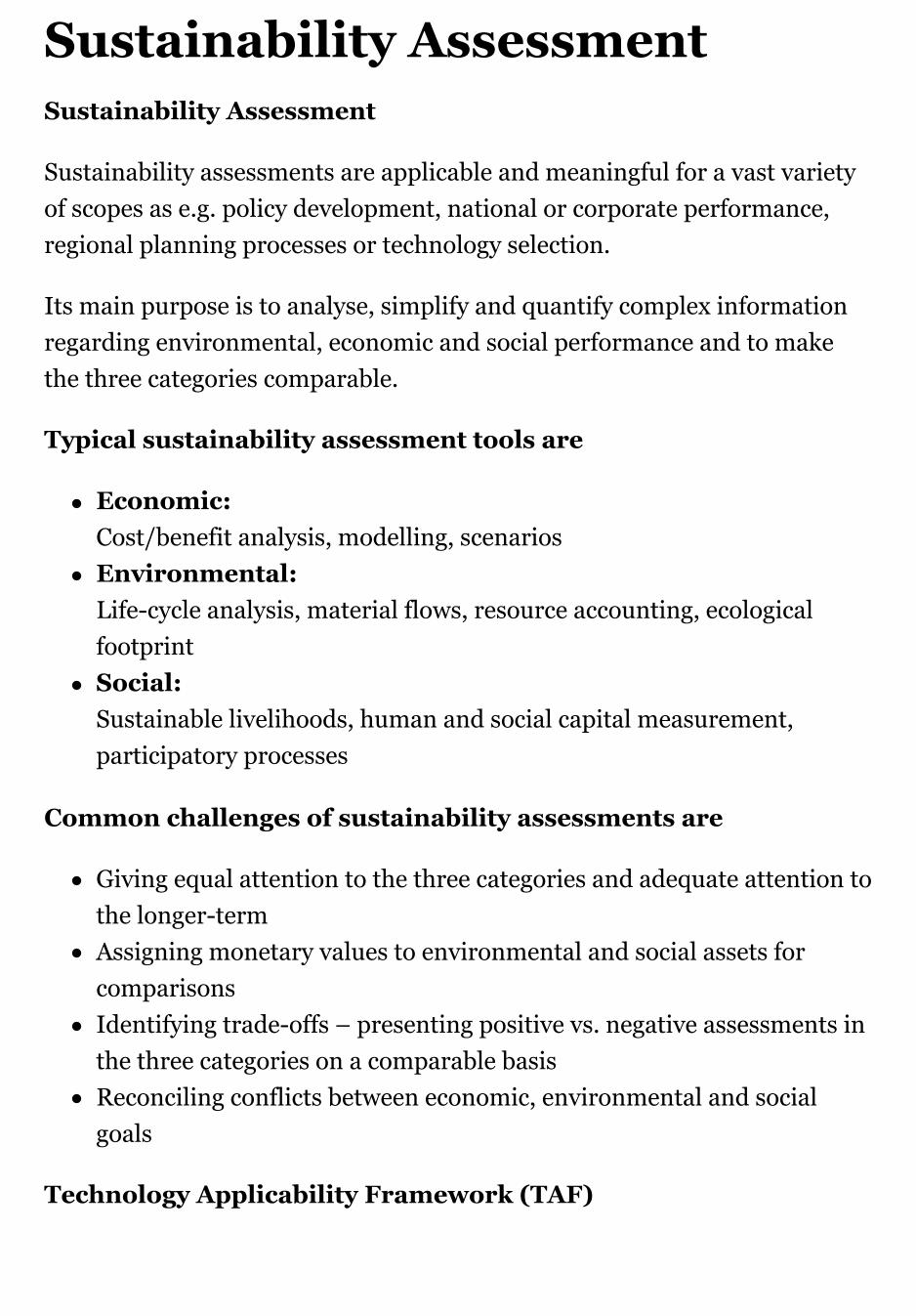
Sustainability AssessmentSustainability Assessment
Sustainability assessments are applicable and meaningful for a vast varietyof scopes as e.g. policy development, national or corporate performance,regional planning processes or technology selection.
Its main purpose is to analyse, simplify and quantify complex informationregarding environmental, economic and social performance and to makethe three categories comparable.
Typical sustainability assessment tools are
Economic:Cost/benefit analysis, modelling, scenariosEnvironmental: Life-cycle analysis, material flows, resource accounting, ecologicalfootprintSocial:Sustainable livelihoods, human and social capital measurement,participatory processes
Common challenges of sustainability assessments are
Giving equal attention to the three categories and adequate attention tothe longer-term Assigning monetary values to environmental and social assets forcomparisonsIdentifying trade-offs – presenting positive vs. negative assessments inthe three categories on a comparable basis Reconciling conflicts between economic, environmental and socialgoals
Technology Applicability Framework (TAF)

TAF Sustainability Criteria
TAF was developed in a «WASHTech» project from Skat Foundation &Water Aid (UK).It offers decision support for technology implementation which aims toanalyse technologies and their readiness to provide sustainable services in agiven context.
Three stakeholder groups are considered:
1. User2. Provider and3. Regulator
Six sustainability dimensions are considered:
1. Environment2. Social3. Economy4. Institutional/legal5. Skills/Know-how6. Technology
[refer to «Further Resources» for more details]