Embed Size (px)
Citation preview

Leica Stereo-Fluorescence
SystemsUser Manual
Manuel d’utilisation
Gebrauchsanweisung
Manual de empleo


3
Contents
Page
Leica MZ FLIIIfluorescence stereomicroscopeDescription . . . . . . . . . . . . . . . . . . . . . . . . . . . . . . . . . . . . . . . . . . . . . . . . . . . . . . . . . . . 4Safety concept . . . . . . . . . . . . . . . . . . . . . . . . . . . . . . . . . . . . . . . . . . . . . . . . . . . . . . . . 4Fluorescence applications . . . . . . . . . . . . . . . . . . . . . . . . . . . . . . . . . . . . . . . . . . . . . 6Components, controls . . . . . . . . . . . . . . . . . . . . . . . . . . . . . . . . . . . . . . . . . . . . . . . . . 8Sets of filters . . . . . . . . . . . . . . . . . . . . . . . . . . . . . . . . . . . . . . . . . . . . . . . . . . . . . . . . . 9
AssemblyOverview . . . . . . . . . . . . . . . . . . . . . . . . . . . . . . . . . . . . . . . . . . . . . . . . . . . . . . . . . . . . 10Focusing drive, microscope carrier, MZ FLIII optics carrier . . . . . . . . . . . . . . . . . 11UV protection screen . . . . . . . . . . . . . . . . . . . . . . . . . . . . . . . . . . . . . . . . . . . . . . . . . 11Model 106Z lamp housing . . . . . . . . . . . . . . . . . . . . . . . . . . . . . . . . . . . . . . . . . . . . . . 12Mercury-vapour lamps . . . . . . . . . . . . . . . . . . . . . . . . . . . . . . . . . . . . . . . . . . . . . . . . 12Stray-light protection . . . . . . . . . . . . . . . . . . . . . . . . . . . . . . . . . . . . . . . . . . . . . . . . . 13Collector, heat-protection filter . . . . . . . . . . . . . . . . . . . . . . . . . . . . . . . . . . . . . . . . . 13Supply units . . . . . . . . . . . . . . . . . . . . . . . . . . . . . . . . . . . . . . . . . . . . . . . . . . . . . . . . . 14Adjusting the mercury-vapour lamp . . . . . . . . . . . . . . . . . . . . . . . . . . . . . . . . . . . . . 15
OperationFLUOIII™ filter system, light stop . . . . . . . . . . . . . . . . . . . . . . . . . . . . . . . . . . . . . . . . 16Adjusting the dioptric setting, focusing, observing . . . . . . . . . . . . . . . . . . . . . . . . . 17
Leica stereo-fluorescence moduleComponents, controls . . . . . . . . . . . . . . . . . . . . . . . . . . . . . . . . . . . . . . . . . . . . . . . . . 18Sets of filters . . . . . . . . . . . . . . . . . . . . . . . . . . . . . . . . . . . . . . . . . . . . . . . . . . . . . . . . 19
AssemblyOverview . . . . . . . . . . . . . . . . . . . . . . . . . . . . . . . . . . . . . . . . . . . . . . . . . . . . . . . . . . . . 20Focusing drive, microscope carrier, optics carrier . . . . . . . . . . . . . . . . . . . . . . . . . 21Fluorescence module . . . . . . . . . . . . . . . . . . . . . . . . . . . . . . . . . . . . . . . . . . . . . . . . . 21Sets of filters . . . . . . . . . . . . . . . . . . . . . . . . . . . . . . . . . . . . . . . . . . . . . . . . . . . . . . . . 21UV protection screen . . . . . . . . . . . . . . . . . . . . . . . . . . . . . . . . . . . . . . . . . . . . . . . . . 22Model 106Z lamp housing . . . . . . . . . . . . . . . . . . . . . . . . . . . . . . . . . . . . . . . . . . . . . . 12Mercury-vapour lamps . . . . . . . . . . . . . . . . . . . . . . . . . . . . . . . . . . . . . . . . . . . . . . . . 12Stray-light protection . . . . . . . . . . . . . . . . . . . . . . . . . . . . . . . . . . . . . . . . . . . . . . . . . 13Collector, heat-protection filter . . . . . . . . . . . . . . . . . . . . . . . . . . . . . . . . . . . . . . . . . 13Supply units . . . . . . . . . . . . . . . . . . . . . . . . . . . . . . . . . . . . . . . . . . . . . . . . . . . . . . . . . 14Adjusting the mercury-vapour lamp . . . . . . . . . . . . . . . . . . . . . . . . . . . . . . . . . . . . . 15
OperationFilter changer, light stop, double-iris diaphragm . . . . . . . . . . . . . . . . . . . . . . . . . . . 23Adjusting the dioptric setting, focusing, observing . . . . . . . . . . . . . . . . . . . . . . . . . 23
EN

4
Description
Fluorescence techniqueSome substances fluoresce when irradiated with short-wavelight. This property is utilized in the fluorescence technique, inwhich certain structures and features which do not fluorescen-ce can be tagged with a fluorescing dye. An example is green-fluorescing protein (GFP), which is used in molecular biology.
Stereo-fluorescenceWith Leica fluorescence systems you can complete unpreparedfluorescing specimens to be non-destructively studied in threedimensions, manipulated, sorted and recorded. The intense lightemitted by the mercury-vapour burner, used in conjunction withselected filter sets, enables even the finest structures to bedifferentiated and expands the amount of information revealedby the incident-light fluorescence technique.
Fluorescence stereomicroscopeThe Leica MZ FLIII with 12.5:1 zoom is the high-performancestereomicroscope for fluorescence applications. The patentedseparate beam path (TriBeam™) for the fluorescence illuminatorand the patented filter system (FLUOIII™) together produceexcellent fluorescence images.
Stereo-fluorescence moduleThe stereo-fluorescence modul can be combined with the Leica stereomicroscope models MS5, MZ6, MZ8, MZ12 andMZAPO, and with older models.
User manualThe present user manual describes only the functions of the fluorescence illuminator, the use of the filter sets, and the fittingof the fluorescence module. For detailed information about theuse of the stereomicroscope, its care and its safety, please referto those sections of the separate manual M2-143-004 which relate to the Leica MZ12 with 12.5:1 zoom.
Safety conceptBefore you set up the instrument and before you fit the fluorescence illuminator, read:• this user manual, observing the notes relating to safety
• the user manual for your stereomicroscope, observing thenotes relating to safety and care.
Permitted usesLeica stereo-fluorescence systems are equipped with a specialfluorescence illuminator. They are intended for the three-dimensional observation of fluorescing objects. They consist of:– a stereomicroscope with stand, binocular tube and
eyepieces
– an integrated FLUOIII filter system (for MZ FLIII) or a separate stereo-fluorescence module
– appropriate filter sets with barrier- and excitation filters, a light stop, and individually-selectable filters
– a UV protection screen
– a lamp housing with high-pressure mercury vapour burner
– a supply unit with power cable.
Prohibited usesThe use of Leica stereo-fluorescence systems in a differentmanner from that described in this user manual can lead toinjury, malfunction and damage.– Do not fit different plugs or cables
– Do not dismantle or modify components unless instructionsfor doing so are given in the user manual
– Components may only be opened by authorized personnel.
Place of useLeica stereo-fluorescence systems are intended for use in closed rooms and may not be used outdoors.
Responsibilities of person in charge of instrument– Ensure that the Leica stereo-fluorescence systems are
operated, maintained and repaired only by authorized andtrained personnel
– Ensure that personnel who use the instrument have read and understood this user manual and in particular all safetyinstructions.

5
Servicing and repairs– Repairs may only be carried out by Leica-trained service
technicians or by technical personnel authorized to do so bythe person in charge of the instrument
– Only original Leica spare parts may be used
– Unplug the power cable before opening the supply unit.Touching live circuits can cause injury.
Legal requirementsAdhere to general and local regulations relating to accident prevention and environmental protection.
Conformity with European Community directive Leica stereo-fluorescence systems and their accessories areconstructed in accordance with the latest technologies and areprovided with a statement of conformity with EC requirements.
Light source: Safety regulations
Safety measures introduced by manufacturer– UV protection screen in front of the specimen plane prevents
direct UV radiation from reaching the eyes.
– Dummy filter carriers in the unoccupied positions of the rapidfilter changer prevent direct UV radiation from reachingthe eyes
– UV filters in the observation beam paths protect the eyesagainst UV radiation.
– Stray-light protection on the underside of the lamp housingprotects the user's hands against UV radiation.
WarningUV can damage your eyes. Therefore:– Never look at the light spot on the specimen plane without
the UV protection screen in position
– Never look into the eyepieces unless there is an excitationfilter in the beam path
– Always keep dummy filter carriers in the unoccupied positions of the rapid filter changer (for MZ FLIII)
– Do not place the specimen on a white or highly-reflectivebackground.
Supply unit• Pull the power plug of the supply unit out from the power
socket:
– when assembling and dismantling the lamp housing
– before opening the lamp housing
– when changing the mercury-vapour burner and other components such as the heat-protection filter or the collector
– when servicing the supply unit
Lamp housing• Never open the lamp housing while the burner is switched on
(risk of explosion, UV irradiation, dazzling)
• Always allow the lamp housing to cool for at least 15 minutesbefore opening it (risk of burner exploding)
• Never cover the ventilator slots on the lamp housing (risk of fire)
Mercury-vapour lamp• Read the user manual and safety directions provided by the
manufacturer of the mercury-vapour burner, and particularlythose relating to its breakage and to the release of mercury
• Before transporting the equipment, remove the mercury-vapourburner and place it in its original packaging. Use the transportpeg in place of the burner, to secure movable parts within thelamp housing
• When the mercury-vapour burner has reached the end of itsnominal working life as indicated by the manufacturer’s information and the time counter on the supply unit, change thediscoloured burner (increased risk of explosion)
• Leica declines all responsibility for injury and damage resulting from exploding, incorrectly-fitted or incorrectly-usedmercury-vapour burners.
EN

6
ApplicationsNatural science Application Fluorescence filter set
Anatomy • Monitoring of capillary flow • GFP, GFP Plus
Biology • Gene expression in chicken embryos, fruit flies, • GFP, GFP Plusthreadworms and zebra fish
• Fish otoliths marked with alizarine red • Green• Genetic expression through viruses and bacteria • GFP Plus
which infect plants and animals
Biomedicine • Humatic seals on pacemakers • Blue, green
Genetics • Cellular detection and protein expression • GFP, GFP Plus• Sorting and dissection• Monitoring developmental processes
Neurology • Gap junctions on muscles and nerves • GFP, violet
Ophthalmology • Cell development in rats' eyes • GFP, GFP Plus
Pharmacy • Drugs • GFP, GFP Plus• ELI spotting in cell structures • Green• Monitoring of capillary flow with FITC • GFP Plus
Plants and seeds • Plants, genetic expression, transgenetics • GFP, GFP Plus• Bacteria detection
Botany • Plant cells, plant surfaces, soil samples • GFP Plant
Hydrology • Water quality (bacterial and other pollutants) • UV• Filtered water • GFP• Cell structures in and on the filter membrane • GFP
Parasitology • Detection of bacteria on ticks • GFP, GFP Plus
Forestry • Development of environmentally-acceptable methods of pest control • GFP(investigation of viruses on pests)
7
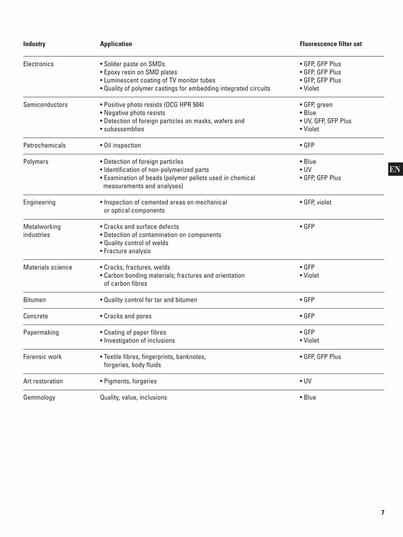
Industry Application Fluorescence filter set
Electronics • Solder paste on SMDs • GFP, GFP Plus• Epoxy resin on SMD plates • GFP, GFP Plus• Luminescent coating of TV monitor tubes • GFP, GFP Plus• Quality of polymer castings for embedding integrated circuits • Violet
Semiconductors • Positive photo resists (OCG HPR 504) • GFP, green• Negative photo resists • Blue• Detection of foreign particles on masks, wafers and • UV, GFP, GFP Plus• subassemblies • Violet
Petrochemicals • Oil inspection • GFP
Polymers • Detection of foreign particles • Blue• Identification of non-polymerized parts • UV• Examination of beads (polymer pellets used in chemical • GFP, GFP Plus
measurements and analyses)
Engineering • Inspection of cemented areas on mechanical • GFP, violetor optical components
Metalworking • Cracks and surface defects • GFPindustries • Detection of contamination on components
• Quality control of welds• Fracture analysis
Materials science • Cracks, fractures, welds • GFP• Carbon bonding materials; fractures and orientation • Violet
of carbon fibres
Bitumen • Quality control for tar and bitumen • GFP
Concrete • Cracks and pores • GFP
Papermaking • Coating of paper fibres • GFP• Investigation of inclusions • Violet
Forensic work • Textile fibres, fingerprints, banknotes, • GFP, GFP Plusforgeries, body fluids
Art restoration • Pigments, forgeries • UV
Gemmology Quality, value, inclusions • Blue
EN

8
Overview
Leica MZ FLIII: Its components and controls1. Choice of stand and of focusing drive (manual or motor-driven)
2. Microscope carrier for Leica MZ FLIII
3a. Leica MZ FLIII optics carrier with third beam path
3b. Integrated FLUOIII filter system
3c. Adapter for light source
3d. Rapid filter changer for any of four sets of filters
3e. Slots for light stop and for filter slide with individually-selectable filter
4a. Leica 106Z lamp housing for 50W or 100W high-pressuremercury vapour burners
4b. Stray-light protection
5. Supply units for 106Z lamp housing (not illustrated)
6. UV protection screen with arm
7. Double-iris diaphragm (optional)
8. Choice of binocular tube, or video-/phototube (optional)
4a3e3c
4b2
1
8
3b3d
3a
6

9
Filter sets Designation Excitation filter Barrier filter
GFP fluorescence GFP1 425/60 nm 480 nm
GFP Plus fluorescence GFP2 480/40 nm 510 nm
GFP plant fluorescence GFP3 470/40 nm 525/50
UV fluorescence UV 360/40 nm 420 nm
Violet fluorescence V 425/40 nm 475 nm
Blue fluorescence B 470/40 nm 515 nm
Green fluorescence G 546/10 nm 590 nm
Filter carrier, empty
Filter sets for Leica MZ FLIII
Tra
nsm
issi
on
1 0 0 %
5 0 %
0 %4 0 0 n m 5 0 0 n m 6 0 0 n m 7 0 0 n m Wave len g th
Filter set GFP Plus for LEICA MZ FLIII
G F P - P L U S . D R W
3 5 0 n m
Excitation Filter (480/40) Barrier Filter (510)
Tra
nsm
issi
on
1 0 0 %
5 0 %
0 %4 0 0 n m 5 0 0 n m 6 0 0 n m 7 0 0 n m Wave len g th
Filter set UV for LEICA MZ FLIII
U V - S P E K . D R W
3 5 0 n m
Excitation Filter (360/40) Barrier Filter (420)
Tra
nsm
issi
on
1 0 0 %
5 0 %
0 %4 0 0 n m 5 0 0 n m 6 0 0 n m 7 0 0 n m Wave len g th
Filter set Blue for LEICA MZ FLIII
B L U - S P E K . D R W
3 5 0 n m
Barrier Filter (515)Excitation Filter (470/40)
Tra
nsm
issi
on
1 0 0 %
5 0 %
0 %4 0 0 n m 5 0 0 n m 6 0 0 n m 7 0 0 n m Wa ve l eng t h
Filter set GFP Plant for LEICA MZ FLIII
G F P - P L N T . D R W
3 5 0 n m
Excitation Filter (470/40) Barrier Filter (525/50)
Tra
nsm
issi
on
1 0 0 %
5 0 %
0 %4 0 0 n m 5 0 0 n m 6 0 0 n m 7 0 0 n m Wave len g th
Filter set GFP for LEICA MZ FLIII
G F P - S P E K . D R W
3 5 0 n m
Excitation Filter (425/60) Barrier Filter (480)
Tra
nsm
issi
on
1 0 0 %
5 0 %
0 %4 0 0 n m 5 0 0 n m 6 0 0 n m 7 0 0 n m Wave len g th
Filter set Violet for LEICA MZ FLIII
V I O - S P E K . D R W
3 5 0 n m
Excitation Filter (425/40) Barrier Filter (475)
Tra
nsm
issi
on
1 0 0 %
5 0 %
0 %4 0 0 n m 5 0 0 n m 6 0 0 n m 7 0 0 n m Wave len g th
Filter set Green for LEICA MZ FLIII
G R E - S P E K . D R W
3 5 0 n m
Excitation Filter (546/10) Barrier Filter (590)
EN

10
Leica MZ FLIIIAssembly1. Incident- or transmitted-light base
2a.Manual focusing drive, or
2b.Motorized focusing drive
3. Microscope carrier for Leica MZ FLIII
4. Leica MZ FLIII optics carrier with FLUOIII™ filter system
5a.Lamp housing 106Z
5b.Stray-light protection
6. Binocular tube
7. UV protection screen with arm
8. 4 sets of filters
9. Light stop
10. Filter slide for an individually-selectable filter
11. Double-iris diaphragm (optional)
12. Trinocular or HU video-/phototube (optional)
4
5a
2a
8
1
3
6
7
2b
910
1212
5b

11
Leica MZ FLIII
Focusing drive ➜ base of stand
E Connect manually-operated or motor-driven focusing drive,complete with column, to base, as described in user manualM2-143-004.
Before using the motor focus, you must read the safety directions in the accompanying user manual M2-267-104.
Microscope carrier ➜ focusing drive
E Fit microscope carrier of Leica MZ FLIII to focusing drive inaccordance with user manual M2-143-004.
Optics carrier ➜ microscope carrier
The Leica MZ FLIII optics carrier and the FLUOIII filter system form a single unit which was factory-adjusted. Do not try to dismantle it.
E Fit the Leica MZ FLIII optics carrier to the microscope carrier in accordance with the user manual M2-143-004.
Additional components
E Fit the remaining components, such as binocular tube,eyepieces and optional double-iris diaphragm, to the FLUOIIIfilter system in accordance with user manual M2-143-004.
Video-/phototube
To permit shorter exposure times in fluorescence photography,we recommend you to use the video-/phototube HU with 100%light in the video-/photo beam path.
E The video-/photo outlet can be positioned on the right or onthe left.
E Fit the video-/phototube to the FLUOIII filter system in accor-dance with the user manual for the Leica photomicrographyor video system.
Double-iris diaphragm
The double-iris diaphragm is used to increase the depth of field(see user manual M2-143-004).
E Fit the double-iris diaphragm to the FLUOIII filter system.
UV protection screen ➜ microscope carrier
E Using a hollow screw, fit the UV protection screen to themicroscope carrier on either the left or the right.
Always position the UV protection screen so that the user can never look directly at the light spot (see page 4):
E Fit the UV protection screenwith arm, at the side.
E Release the hollow screw.
E Adjust the UV protectionscreen, upwards or downwards.
E Tighten the hollow screw.
EN
12
Assembly
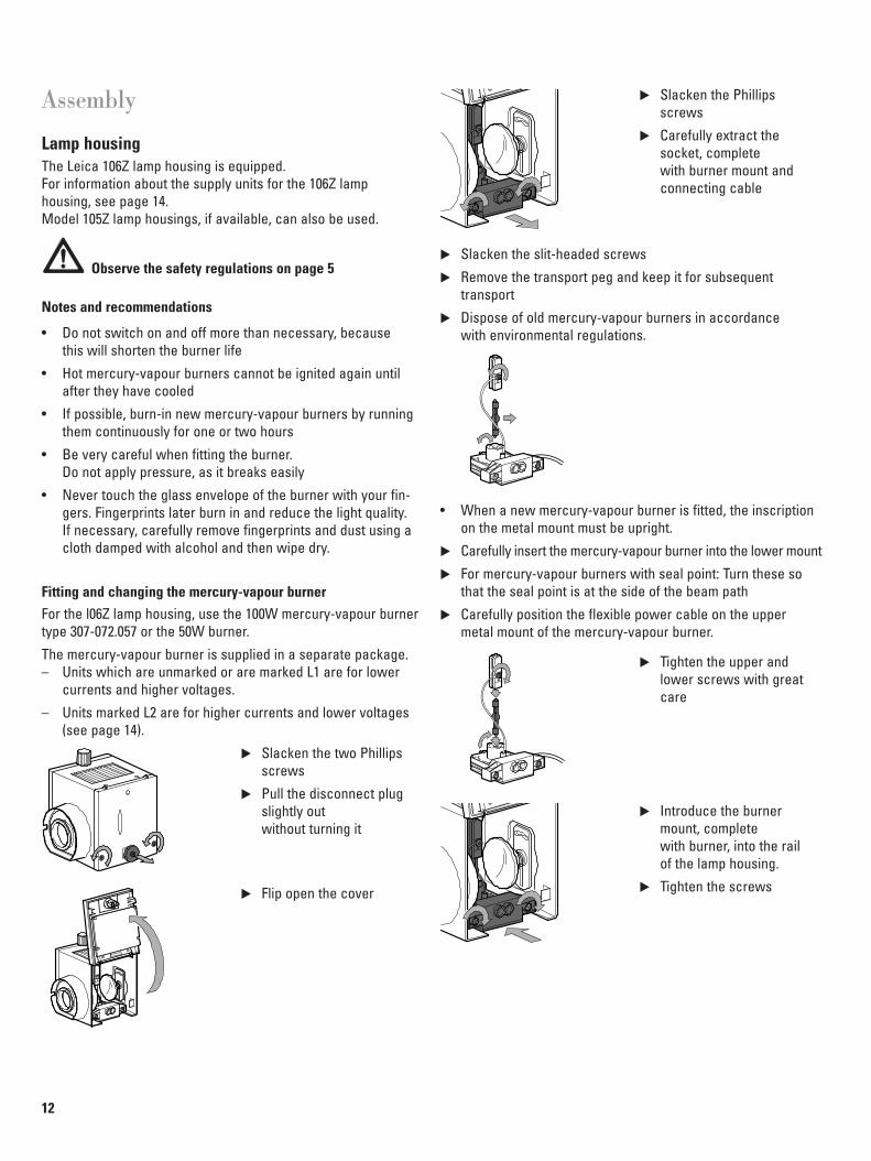
Lamp housingThe Leica 106Z lamp housing is equipped.For information about the supply units for the 106Z lamp housing, see page 14.Model 105Z lamp housings, if available, can also be used.
Observe the safety regulations on page 5
Notes and recommendations
• Do not switch on and off more than necessary, because this will shorten the burner life
• Hot mercury-vapour burners cannot be ignited again untilafter they have cooled
• If possible, burn-in new mercury-vapour burners by runningthem continuously for one or two hours
• Be very careful when fitting the burner. Do not apply pressure, as it breaks easily
• Never touch the glass envelope of the burner with your fin-gers. Fingerprints later burn in and reduce the light quality. If necessary, carefully remove fingerprints and dust using acloth damped with alcohol and then wipe dry.
Fitting and changing the mercury-vapour burnerFor the l06Z lamp housing, use the 100W mercury-vapour burnertype 307-072.057 or the 50W burner.
The mercury-vapour burner is supplied in a separate package. – Units which are unmarked or are marked L1 are for lower
currents and higher voltages.
– Units marked L2 are for higher currents and lower voltages (see page 14).
E Slacken the two Phillipsscrews
E Pull the disconnect plugslightly out without turning it
E Flip open the cover
E Slacken the Phillips screws
E Carefully extract thesocket, complete with burner mount and connecting cable
E Slacken the slit-headed screws
E Remove the transport peg and keep it for subsequent transport
E Dispose of old mercury-vapour burners in accordance with environmental regulations.
• When a new mercury-vapour burner is fitted, the inscriptionon the metal mount must be upright.
E Carefully insert the mercury-vapour burner into the lower mount
E For mercury-vapour burners with seal point: Turn these sothat the seal point is at the side of the beam path
E Carefully position the flexible power cable on the uppermetal mount of the mercury-vapour burner.
E Tighten the upper andlower screws with greatcare
E Introduce the burnermount, complete with burner, into the rail of the lamp housing.
E Tighten the screws

13
E Using the focusing knob,displace the collector:
• During this movement, thecollector must not touchthe flexible power cable. Ifnecessary, bend the cableaway
E Carefully close the lamp housing, making sure that the disconnect plug engages the socket
E Press in the disconnect plug slightly
E Tighten the screws
E Push the disconnect plug fully in to the stop without turning it.
Lamp housing assemble
E Using the Allen key, releasethe hollow screw
E Introduce the lamp housinginto the adapter of the fluorescence module andtighten the hollow screw.
Stray-light protection
There are slots in the lamp housing through which UV light canshine on the user's hands during manipulations beneath thehousing. The stray-light protection on the underside of the lamphousing is designed to block this light.
E Secure the stray-light protection with two screws.
Removing the collector and the heat-protection filter
The collector and the heat-protection filter can be removed for cleaning or if defective.
E Open the lamp housing as described on page 12 and removethe burner socket
E Move the reflector fully tothe right-hand stop
E Hold the collector and pullout the focusing knob
E Extract the collector
E Slacken the two screwsand remove the heat-protection filter from thecollector
E Screw a new heat-protection filter into position
Replacing the collector
E Pull out the focusing knob
E Carefully replace the collector and move it to the left until the focusing knob engages the guide groove
E Test the displacement of the collector
E Refit the burner socket (page 12) and close the lamphousing.
EN

14
Fuses
The fuse holder is secured in the holder with spring clips on both sides.
E Insert a screwdriver behind the spring clips and extract the fuse holder.
E Insert the fuses (2× T3,15A H250V F1/F2).
E Refit the fuse holder
Assembly
Supply unit for lamp housing 106Zwith 50W mercury-vapour burner1. On/off switch
2. Running-time meter
3. Selector for L1/L2 burners
4. Fuse
5. Selector for 50Hz/60Hz
6. Connector for lamp
7. Power cable
The supply unit is intended for power supplies above 220V. To run it on lower voltages a step-down transformer is required(e.g. 230V to 110V).
Observe the safety regulations on page 5.
E Connect the cable from the lamp housing to the supply unit
E Engage “L1” or “L2” in accordance with the inscription on the burner socket (see page 12)
E Engage 50Hz or 60Hz
E Connect the power cable to the supply unit and to the grid
E Make a note of the running-time meter reading.
Supply unit for lamp housing 106Z with 100W mercury-vapour burner1. On/off switch
2. Pilot lamp LAMPE
3. Pilot lamp TEMP
4. Running-time meter
5. Connection for power
6. Fuse holder for two fuses
7. Lamp connection
Observe the safety regulations on page 5
E Connect the cable from the lamp housing to the supply unit
E Secure the lamp cable.
E Connect the power cable to the supply unit and to the grid
E Make a note of the running-time meter reading.
Input type220V/240V ±10%220V ~50/60HzHg50W L1/L2Osram no. 0-958Max. power 320VA
Type ebq 100dcInput voltage 90V to 250V AC, max 265VAInput frequency 48Hz to 63 HzProtection class IP20Series no. G 34240090
2 1 6 7
543
2 3
1

15
3
2
1
54
6
Hg 50W Hg 100W
Adjusting the mercury vapour lamp
This adjustment is important for obtaining a uniform light spotand good-quality fluorescence.
While adjusting the mirror image, do not project light on to the electrodes for long periods (risk of explosion through overheating)
The two electrodes are imaged as an extension of the plane of symmetry of the discharge arc, but are difficult to see.
E Switch on the supply unit and wait for two or three minutes
• The 100W supply unit emits a whistle
E Swing out the UV-light excluder (page 21)
• Work without the UV-light excluder is only permitted foradjustment, and then only for short periods
E Pull out the light stop (see page 16, MZ FLIII and page 22,Fluorescence module).
E MZ FLIII: Turn the filter set in the beam path (page 16).
E Stereo-fluorescence module: Insert the excitation filter (page 22).
E Mark a cross on a piece of paper and place it in the middleof the illuminated spot
E Select the lowest magnification
• The discharge arc is visible in the illuminated spot and lies at about 45° to the lines of the cross (fig. a)
E Look into the eyepieces and focus on the cross
E Using your unaided eye, observe the discharge arc on thepaper and bring it into focus with the focusing knob (3) (fig. a)
E Using the positioning knobs (1 and 2), displace the dischargearc (fig. b)
E Bring the mirror image of the discharge arc into focus with the knob (6) and use the knobs 4 and 5 to position itsymmetrically relative to the original image (fig. c)
• For the 50W burner, the discharge-arc image and its mirror image should touch
• For the 100W burner, the discharge-arc image and its mirrorimage should be superimposed.
E Using the focusing knob (3), readjust the illuminated field
• The illuminated field should now be large, circular and as uniform as possible
E Reposition the UV-light excluder correctly (page 21).
Figs. a: Bringing the discharge arc into focus
Figs. b: Positioning the discharge arcrelative to the cross
Figs. c: Focusing and positioning themirror image of the discharge arc
EN

16
Leica MZ FLIII
FLUOIII filter systemThe filter system consists of a rapid filter changer for the barrier- and excitation filters and two slots for a light stop andfor a filter slide respectively.
Rapid filter changer
The rapid filter changer of the Leica MZ FLIII accepts a total offour sets of filters. These are inscribed (see table on page 9).Each filter set consists of two barrier filters for the observationbeam paths and one excitation filter for the illumination beampath.To avoid fingerprints on the filters in the filter sets, try to avoidtouching them. If fingerprints do occur, remove them with aclean lint-free cloth and pure alcohol.An empty filter carrier is available for individual filter combinations.
E Insert a set of filters into the rapid filter changer so that theinscription (e.g. GFP) is upright and on the right-hand side.Make sure that the shape of the filter set follows the shapeof the instrument.
E Turn the filter set until itengages.
E Insert a total of four sets offilters, or insert dummy filter carriers if the numberis less.
If you use less than four filter sets, you must insert in the free spaces the dummy filter carriers provided. If you leave spaces unfilled, you risk eye damage from direct UV radiation from the third beam path (see page 5).
Dummy filter carrier
In the dummy filter carrier there are two openings for the observation beam paths instead of the barrier filters. The thirdpath has been closed. Use the dummy filter carrier:– if you are using less than four sets of filters
– if you are working without the fluorescence illuminator forperiods of up to 15 seconds.
• Do not use the dummy filter carrier to block the light from themercury-vapour burner for more than 15 seconds, or it willheat up. Use the light stop instead.
Light stop
The FLUOIII filter system includes a slot for the light stop. In phases where the object is to be examined in e.g. transmittedlight instead of under conditions of fluorescence, the light stop isused to block the illumination beam path so that the mercury-vapour burner does not have its life shortened by being switchedon and off more than is absolutely necessary (see page 5).
Filter slide
Next to the light stop is a slot accepting a filter slide which can hold an individually-selectable filter, e.g. a grey filter.
Working without the fluorescence illuminator
E Use the light stop to blockthe light from the fluorescence illuminator.
E Turn the dummy filter carrier in the observation beam path so that there is no barrier filter in position which mightcause false colour.

17
Use
MZ FLIII: Bringing the specimen into focus and observing it
Observe the safety directions on page 4 and the recommendations on page 5 regarding the use of the mercury-vapour lamp.
Changing filters
In the rapid filter changer, all four positions must be occupied,either with filter sets or with dummy filter carriers (see page 16).The active filter set is always the one with its inscription on theleft.
E Turn the sets of filters until the inscription on theone required is visible onthe left.
Dioptric correction
We recommend you to carry out the dioptric correction either intransmitted light or in incident light:
E If the fluorescence illumi-nator is switched on, usethe light stop to block thelight (page 16).
E Swing the dummy filtercarrier into the beam path(page 16).
E Illuminate a flat test object with transmitted light or with oblique incident light.
E Carry out the dioptric correction as directed in the usermanual for the stereomicroscope.
Observing fluorescence
Make sure that the UV protection screen is positioned correctly (page 11).
E Turn the required filter set into the beam path (page 16).
E Switch on the supply unit (pages 14) and wait for two orthree minutes.
E Pull out the light stop (page 16).
E Using the lowest magnification, observe the object.
• This will give you a better overall view and you will be ableto locate features of interest more easily.
E Refocus slightly if necessary.
E Observe the details at higher magnification.
Reflexes (hot-spots)
When the 1.6× planapochromatic objective is used at zoom positions between 0.8 and 1.6, a slight reflex (hot-spot) occurs in the lower part of the field of view; it disappears at higher zoompositions. This reflex does not arise in conjunction with the 1.0× and 0.5× planapochromatic objectives or the achromaticobjectives.
EN

18
Overview
Outfit with stereo-fluorescence module
The components1 Choice of stand and of focusing drive
(manual or motor-driven)
2 Microscope carrier
3 Leica MS5, MZ6, MZ8, MZ12 or MZAPO optics carrier
4a Leica stereo-fluorescence module with choice of barrier filter
4b Filter insert for excitation filter
4c Light stop
4d Filter holder with an individually-selectable filter
4e Adapter for light source
5a, 5b
4e
4b, 4c, 4d
6
1
2
9
4a
83
7
5a Leica 106Z lamp housing for 50W or 100W mercury-vapourburners
5b Stray-light protection
6 Supply unit for 50W or 100W mercury-vapour burner(not illustrated)
7 UV-light excluder with arm and clamp
8 Double-iris diaphragm (optional)
9 Choice of binocular tube, or optional video-/phototube

19
Filter sets Excitation Dichromatic Barrierfilters beam splitters filters
GFP fluorescence 425/60nm 470nm GG475
GFP-Plus fluorescence 480/40nm 505nm LP 510nm LP
GFP-Plant 470/40nm 495nm 525/50nm
UV fluorescence 360/40nm 400nm GG420
Violet fluorescence 425/40nm 460nm GG475
Blue fluorescence 470/40nm 505nm OG515
Green fluorescence 546/10nm 565nm OG590
Filter sets for stereo-fluorescence module
EN
20
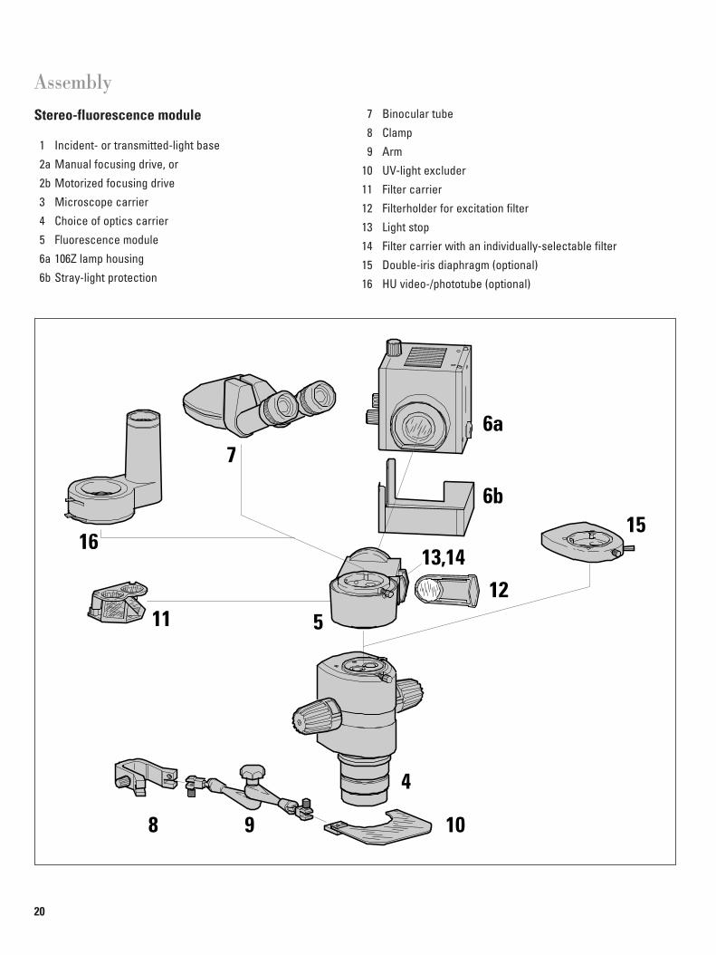
AssemblyStereo-fluorescence module
1 Incident- or transmitted-light base
2a Manual focusing drive, or
2b Motorized focusing drive
3 Microscope carrier
4 Choice of optics carrier
5 Fluorescence module
6a 106Z lamp housing
6b Stray-light protection
4
5
6a
13,1412
15
7
16
11
98 10
6b
7 Binocular tube
8 Clamp
9 Arm
10 UV-light excluder
11 Filter carrier
12 Filterholder for excitation filter
13 Light stop
14 Filter carrier with an individually-selectable filter
15 Double-iris diaphragm (optional)
16 HU video-/phototube (optional)

21
Important: With the illuminator on, insert the filterholder with diaphragm into slide-in unit 3 to avoid being suddenly exposed to excessively bright light (page 22).
E Remove the binocular tube.
E Loosen the 3 socket-headscrews.
E Remove the cover.
E Loosen the fasteningscrew and take out the filter carrier.
E Insert the desired filtercarrier. Fit both of the two guide pins in the fluorescence module into the holes on the filtercarrier.
E Tighten the fasteningscrew securely.
E Replace the cover andtighten the 3 socket-headscrews securely.
E Replace the binocular tube.
E Insert a suitable exciter filter (page 22).
E Take out the filterholder with diaphragm.
E Re-adjust the light source (page 15).
Stereo-fluorescence module
Focusing drive ➜ base of standE Connect manually-operated or motor-driven focusing drive,
complete with column, to base, as described in user manualM2-143-004.
Before using the motor focus, you must read the safety directions in the accompanyinguser manual M2-267-104.
For the Leica stereomicroscope models MS5, MZ6, MZ8, MZ12,MZAPO with manual focusing drive, fit the microscope in the upper position on the focusing drive (refer to user manual forstereomicroscope).
Fluorescence module ➜ stereomicroscope• Assemble in the following order without double-iris dia-
phragm: Optics carrier, fluorescence module, binocular tubeor phototube
• Assemble in the following order with double-iris diaphragm:Optics carrier, double-iris diaphragm, fluorescence module,binocular tube or phototube
E Align the fluorescence module on the optics carrier so thatthe adapter for the lamp housing points backwards at about 45°
E Continue assembling in accordance with the user manual forthe stereomicroscope (see section “Fitting accessory tubes”)
Video-/phototubes
The fluorescence illumination is directed along the left-handbeam path and could cause hot-spots in the image. Therefore:E Position the HU phototube over the right-hand beam path.
Changing the filter set
Removable filter sets that can hold various filters are available forthe fluorescence module. A filter set consists of a filter carrierwith barrier filter and of a filterholder with excitation filter. If you wish to change the filter set while you are in the middle of a task, leave the illuminator switched on so that you will not have to wait for the lamp to cool (page 12) before continuing.
3
EN

22
AssemblyStereo-fluorescence module
UV-light excluder ➜ side-faced column
Always position the UV-light excluder so thatthe user never looks directly at the light spot (page 5)
E Using the clamping screw,secure the clamp on theside-faced column,beneath the focusing drive.
E Slacken the central fixingscrew.
E Unfold the arm.
E Tighten the central fixingscrew.
E Secure the arm, completewith connector, to theclamp, on the left or right.Tighten the clampingscrew.
E Secure the UV-light excluder to the arm. Tighten the clampingscrew.
Filterholder ➜ fluorescence module
The dichromatic beam splitter and the barrier filter are built intothe fluorescence module in accordance with the configuration(see table, page 19).The excitation filter is supplied in a separate filterholder.
A filterholder with diaphragm is also supplied. This diaphragmcan be slid into the illumination beam path if the object shouldnot be illuminated.
The filter slide on the fluorescence module has space for three filterholders:• with excitation filter (holder 1)
• with diaphragm (holder 3)
• with individually-selectable filter, e.g. neutral filter (holder 2).
Double-iris diaphragm
The double-iris diaphragm is used to increase the depth of field(see user manual M2-143-004). Also, the stray reflections arisingin the left-hand beam path can be minimized with the help of the double-iris diaphragm.The HU video-/phototube already includes a double-iris diaphragm.
Additional assembly instructions
Lamp housing pages 12–13
Supply units page 14
Adjusting the mercury-vapour lamp page 15
1 2 3
23
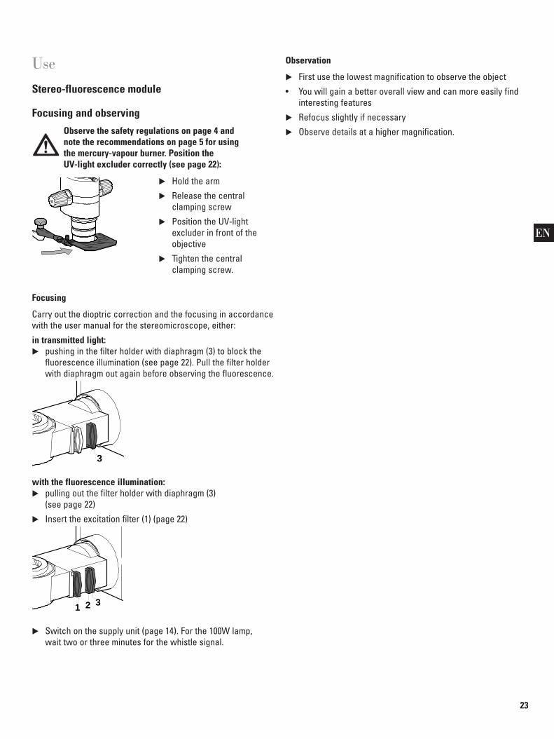
UseStereo-fluorescence module
Focusing and observing
Observe the safety regulations on page 4 and note the recommendations on page 5 for using the mercury-vapour burner. Position the UV-light excluder correctly (see page 22):
E Hold the arm
E Release the central clamping screw
E Position the UV-light excluder in front of theobjective
E Tighten the central clamping screw.
Focusing
Carry out the dioptric correction and the focusing in accordancewith the user manual for the stereomicroscope, either:
in transmitted light:E pushing in the filter holder with diaphragm (3) to block the
fluorescence illumination (see page 22). Pull the filter holderwith diaphragm out again before observing the fluorescence.
with the fluorescence illumination:E pulling out the filter holder with diaphragm (3)
(see page 22)
E Insert the excitation filter (1) (page 22)
E Switch on the supply unit (page 14). For the 100W lamp, wait two or three minutes for the whistle signal.
1 2 3
3
Observation
E First use the lowest magnification to observe the object
• You will gain a better overall view and can more easily findinteresting features
E Refocus slightly if necessary
E Observe details at a higher magnification.
EN

Leica Microscopy Systems LtdBusiness Unit SMCH-9435 Heerbrugg (Switzerland)
Telephone +41 71 727 31 31Fax +41 71 727 46 76http://www.leica.com
© L
eica
Mic
rosc
opy
Syst
ems
Ltd
• CH-
9435
Hee
rbru
gg (S
witz
erla
nd),
1998
• Pr
inte
d on
chl
orin
e-fre
e pa
per w
ith a
hig
h co
nten
t of r
ecyc
led
fibre
.Pu
blic
atio
n no
.: M
2-16
0-00
4 •
engl
ish/
frenc
h/ge
rman
/spa
nish
• Pr
inte
d in
Sw
itzer
land
– I.
99 –
RDV
Leica Microsystems – the brandfor outstanding products
Leica Microsystems – an international company with a strong network of customer servicesAustralia: North Ryde/NSW Tel. +1 800 625 286 Fax +61 29 888 7526Austria: Vienna Tel. +43 1 495 441 60 Fax +43 1 495 441 630Canada: Willowdale/Ontario Tel. +1 800 205 3422 Fax +1 416 497 8516Denmark: Herlev Tel. +45 44 5401 01 Fax +45 44 5401 11Finland: Espoo Tel. +358 9 6153 555 Fax +358 9 5022 398France: Rueil-Malmaison Tel. +33 1 4732 8585 Fax +33 1 4732 8586Germany: Bensheim Tel. +49 6251 1360 Fax +49 6251 136 155Hong Kong: Tel. +8522 564 2299 Fax +8522 564 4163Italy: Milan Tel. +39 2 5740 1955 Fax +39 2 5740 3273Japan: Tokyo Tel. +81 3 3292 9830 Fax +81 3 3292 9777Korea: Seoul Tel. +82 2 514 6543 Fax +82 2 514 6548Netherlands: Rijswijk Tel. +31 703 198 999 Fax +31 703 905 659Norway: Oslo Tel. +47 22 252 270 Fax +47 22 163 232Portugal: Lisbon Tel. +351 1 388 9112 Fax +351 1 385 4668Singapore: Tel. +65 77 97 823 Fax +65 77 30 628Spain: Barcelona Tel. +34 93 494 9530 Fax +34 93 494 9532Sweden: Sollentuna Tel. +46 8 625 45 45 Fax +46 8 625 45 10Switzerland: Glattbrugg Tel. +41 1 809 3333 Fax +41 1 810 7937United Kingdom: Milton Keynes Tel. +44 1908 666 663 Fax +44 1908 609 992USA: Deerfield/Illinois Tel. +1 800 248 0123 Fax +1 847 405 0147
and representatives of Leica in more than 100 countries.
Contact:http://www.leica.comFax +49 6441 293 399
The Leica Microsystems Mission is to be the world's first-choice provider of innovative solutions to our customers’ needs for vision, measurement, lithographyand analysis of microstructures.
Leica, the leading brand for microscopes and scientific instruments, has grown fromfive brand names with a long tradition: Wild, Leitz, Reichert, Jung and CambridgeInstruments. Leica symbolizes both tradition and innovation.
MicroscopesCompoundStereoSurgicalLaser ScanningPhotomicrographyVideo MicroscopyMeasuring Microscopes
Advanced SystemsImage AnalysisSpectral PhotometryAutomated InspectionStationsMeasurement SystemsElectron Beam Lithography
Laboratory EquipmentTissue ProcessorsEmbedding SystemsRoutine & ImmunostainingCoverslippersRefractometers
MicrotomesRotary & SlidingCryostatsUltramicrotomesEM Sample Preparation
The Business Units in Leica Microscopy Systems hold the management systemcertificates for the international standards ISO 9001 and ISO 14001 relating to qualitymanagement, quality assurance and environmental management.


![From Eye to Insight - Leica Microsystems MZ10 F/Applicatio… · Introduction The roundworm ... Leica S6 routine stereo microscope [8] with the LED2500 light stand, or small illumination](https://img.dokumen.tips/doc/110x75/5f1dae6c23323912da18c2ee/from-eye-to-insight-leica-microsystems-mz10-fapplicatio-introduction-the-roundworm.jpg)