Embed Size (px)
Citation preview

IFSM-73-U :
LEHIGH UNIVERSITY \
fee ftt' TV:K' vB*?fJi>te%s3^^^;ig?^.i-Eci fe^vK^i^z-^:/fY^u!V"^.-•.:''":/'''•'•\&!:"f-•<*3'; «•*•?•••:.'.':•".• ' y;l P"**;:-r -. •.'H'• - .-F ' ERDOdAW^f;
MAY 1973
WAtiONAL. AERONAUTICS ywb= SPACE ADMiwrsTRAfION.- K ;: ; : - -\--":':^ GRANT NGR-39-007-On
https://ntrs.nasa.gov/search.jsp?R=19730020154 2018-03-17T20:13:58+00:00Z

INTERACTION BETWEEN A CIRCULAR INCLUSION
AND AN ARBITRARILY ORIENTED CRACK*
. : by
F. Erdogan, G. D. Gupta, M. RatwaniLehigh University, Bethlehem, Pa. 18015
Abstract
The plane interaction problem for a circular elastic inclusionimbedded into an elastic matrix which contains an arbitrarilyoriented crack is considered. Using the existing solutions forthe edge dislocations [6] as Green's functions, first the generalproblem of a through crack in the form of an arbitrary smooth arclocated in the matrix in the vicinity of the inclusion is formu-lated. The integral equations for the line crack are then obtainedas a system of singular integral equations with simple Cauchykernels. The singular behavior of the stresses around the cracktips is examined and the expressions for the stress intensity fac-tors representing the strength of the stress singularities areobtained in terms of the asymptotic values of the density functionsof the integral equations. The problem is solved for varioustypical crack orientations and the corresponding stress intensityfactors are given. :,
1. INTRODUCTION
In fracture studies' of ceramics and other composite materials
it is generally conjectured that the fracture of the solid will
initiate at and will propagate from a "dominant flaw". This may
be a manufacturing flaw, it may be caused by residual stresses or
some other type of loading before the part is put into use, or it
may result from the growth of a "micro flaw" due to cyclic nature
of the operating stresses. In some cases it may be possible to
detect such flaws by using nondestructive testing techniques.
This work was supported by the National Science Foundation underthe Grant GK-11977 and by the National Aeronautics and SpaceAdministration under the Grant NGR 39-007-011.
-1 -
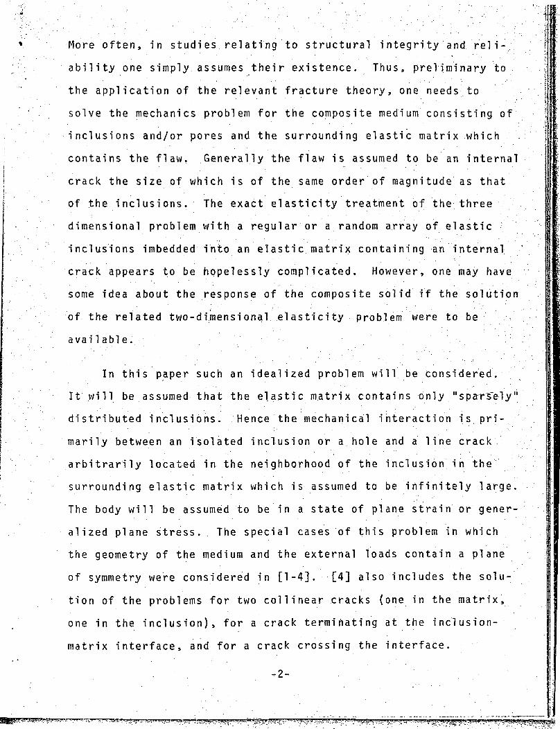
More often, in studies relating to structural integrity and reli-
ability one simply assumes their existence. Thus, preliminary to
the application of the relevant fracture theory, one needs to
solve the mechanics problem for the composite medium consisting of
inclusions and/or pores and the surrounding elastic matrix which .
contains the flaw. Generally the flaw is assumed to be an internal
crack the size of which is of the same order of magnitude as that
of the inclusions. The exact elasticity treatment of the three
dimensional problem with a regular or a random array of elastic
inclusions imbedded into an elastic matrix containing an internal
crack appears to be hopelessly complicated. However, one may have
some idea about the response of the composite solid if the solution
of the related two-dimensional elasticity problem were to be
available.
In this paper such an idealized problem will be considered.
It will be assumed that the elastic matrix contains only "sparTely"
distributed inclusions. Hence the mechanical interaction is pri-
marily between an isolated inclusion or a hole and a line crack
arbitrarily located in the neighborhood of the inclusion in the ",
surrounding elastic matrix which is assumed to be infinitely large.
The body will be assumed to be in a state of plane strain or gener-
alized plane stress. The special cases of this problem in which
the geometry of the medium and the external loads contain a plane
of symmetry were considered in [1-4]. [4] also includes the solu-
tion of the problems for two collinear cracks (one in the matrix,
one in the inclusion), for a crack terminating at the inclusion-
matrix interface, and for a crack crossing the interface.
' . . ' ' • - 2 - . . ' ' • '
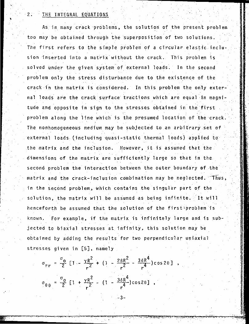
2. THE INTEGRAL EQUATIONS : ' ,
As in many crack problems, the solution of the present problem
too may be obtained through the superposition of two solutions.
The first refers to the simple problem of a circular elastic inclu-
sion inserted into a matrix without the crack. This problem is
solved under the given system of external loads. In the second
problem only the stress disturbance due to the existence of the
crack in the matrix is considered. In this problem the only exter-
nal loads are the crack surface tractions which are equal in magni-
tude and opposite in sign to the stresses obtained in the first
problem along the line which is the presumed location of the crack.
The nonhomogeneous medium may be subjected to an arbitrary .set of
external loads (including quasi-static thermal loads) applied to
the matrix and the inclusion. However, it is assumed that the
dimensions of the matrix are sufficiently large so that in the
second problem the interaction between the outer boundary of. -the
matrix and the crack-inclusion combination may be neglected. ^Thus,
in the second problem, which contains the singular part of the ,
solution, the matrix will be assumed as being inf i ni te. It will
henceforth be assumed that the solution of the first problem is
known. For example, if the matrix is infinitely large and is sub-
jected to biaxial stresses at infinity, this solution may be
obtained by adding the results for two perpendicular uniaxial
stresses given in [5], namely
„ - a° n 1R?. + n 23R2a - -j- ii -- •i—y- + (\ - — —. r r
-3-
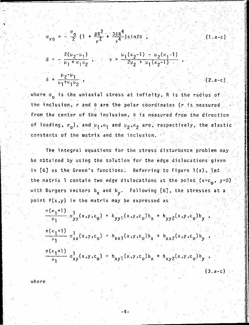
°o 6R • 36Rtf.fi = - -o- 0 + —T + —A-)sin28 , (1 . a - c )re
^6 = " ' Y =
. .. .5 = u^ ' (2.a-c)
where a is the uniaxial stress at infinity, R is the radius of
the inclusion, r and 6 are the polar coordinates (r is measured •
from the center of the inclusion, 8 is measured from the direction
of loading, a ) ,' and :'u ,K^ and y^^? are» respectively, the elastic
constants of the matrix and the inclusion.
The integral equations for the stress disturbance problem may
be obtained by using the solution for the edge dislocations given
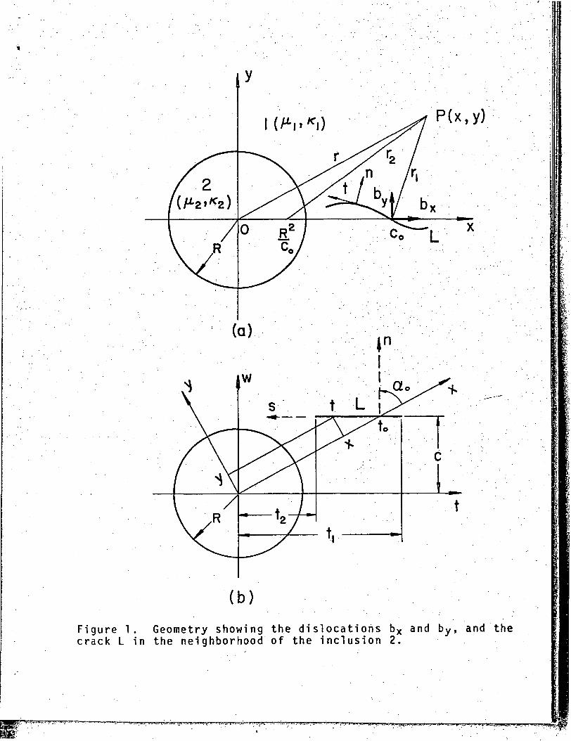
in [6] as the Green's functions. Referring to Figure l(a), let
the matrix 1 contain two edge dislocations at the point (x=c,y=0)
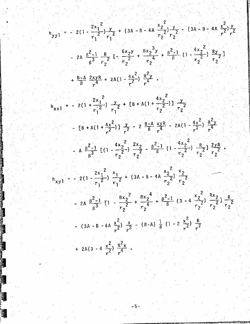
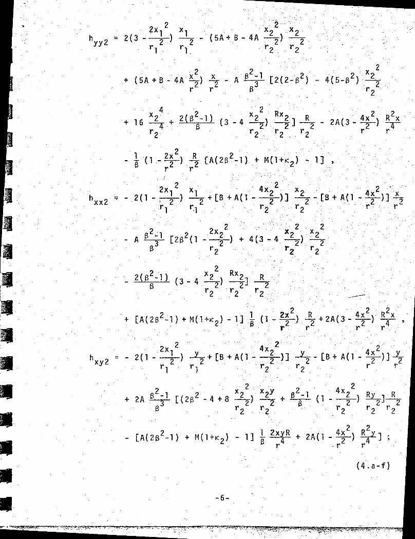
with Burgers vectors bv and bu. Following [6], the stresses at a..''•' • • ' • • y . • • . • . . .••••'point P(x,y) in the matrix may be expressed as
TT(IC,-H) ; , ; • • : . • - . •-ITj - - O y y t x . y , c 0 ) = h y y l ( x , y , c 0 ) b x + h y y 2 (x ,y . , c 0 )b y • ,
-^— a ^ x ( x , y , c 0 ) = h x x l ( x , y , c o ) b x + h x x 2 ( x , y , c 0 ) b y ,
TT(K ,+ I ) .
— - ^ x y ^ ^ ' y ^ o 5 = h x y l ( x ' y ' c o ) b x + h x y 2 ( x ' y ' c o ) b y .'
( 3 . a - c )
w h e r e
-4-
P(x,y)
(b)
Figure 1. Geometry showing the dislocations bx and by, and thecrack L in the neighborhood of the inclusion 2.
W2(1-2x-
(3A -B - 4 A ; - ?
r
- (3A- B- 4A 75-)r r
- 2A2 T2
B-A2 R2y
~
4x,hxxl = - 2(1
- [Br r'
'xyl
2
rl rl 2 2
8x- 2A-
24
'2
,-1
• r2 r2
(3A -B -4A \) 2-r r • r r
2A(3 -4 y) -r r
-5-
W •' 2(3 -?Y v y xC. A -i *^T 0 f\ *\ .
——^ -~ - (5A> B - 4A —) -^jr2 r2
( 5 A - J - B - 4A-£5- ) 4- - A - C 2 ( 2 - 3 2 ) - 4 (5 -$ 2 )
.16 (3 -4 ^2) ^fr r
-
2x, . '.*.hxx2 V - . ' 2 n- r
4Xg X2- ) J ;
rZ r2
.2 '
r - r
2
3
2x+ 4 ( 3 - 4
2 •x x
r2 r2
M . X2 x Rx2-, R( 3 - 4 y) 5-J—2~/ —2"J —2
r2 r2 T2
-1] r r ^)r r
h x y 2 = - 2 < 1 -rl rl
r r
2A ^J- [ ( 2 3 ^ - 4 +8 •-1 4x,
2 - 2. 2 •'. 22 r2 r2
- [A (2B -r . r
(4 .a - f )
-6-
-r-^-T '- iT-*- .-"" ^ sim f!

.£R » A =
M =m(l+K 1
l-m
2m)
B =
(5)
Xl = X2 = X'F r2 =
= (x-c) (6)
Let us now assume that the matrix contains a cut along a smooth
arc L going through the point (c ,0) (Figure la). Let a (s) and
ct(s), (s6L) be the normal and tangential components of the stress
vector on L in the composite without the cut and subjected to the
given set of external loads, where s is the arc length measured oni . • . "
L (i.e., the solution of the first problem). Let the point (cQ,0)
correspond to s = s on L. Once L is specified, from (3) we may
also obtain the normal and tangential stresses on L due to
dislocations b and b only. as follows:x y
a n ( s > s o > = hnl ( s ' so ) bx + h n 2 ( s ' s o > b '
=' htl(s,s.0)bx' + ht2(s,s0)by , (7.a,b)
where h - a n d h. . , (i=l ,2) may be obtained from (4) by using the
coordinates on L. If n and t refer to the positive normal and
tangent to L at s (Figure la) and if a = a(s) is the angle between
the x-axis and the normal n, noting that (3) is also valid for
(x,y)€L, ab and a^ are given by
K 1 9 1 9 1n = a!v cos a + a sin a + 2a sinacosa ,n xx jj . ™j
I T
" axx)sinacosa a " sin (8.a,b)
-7-
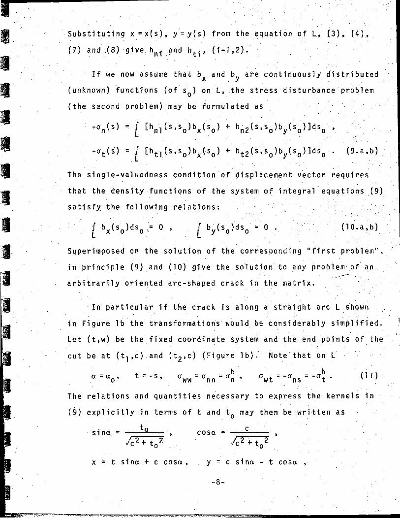
Substituting x=x(s), y = y(s) from the equation of L, (3), (4),
(7) and (8) give h. and h.., (i=l,2).I l l ' " l # 1 ~ ' . ' . ' • •
If we now assume that b and bu are continuously distributed• x y(unknown) functions (of s ) on L, the stress disturbance problem
(the second problem) may be formulated as
-«„(*).•> / thn:,(».se)bx(s0.) * hn2(s,s0)by(s0)]ds0 ,
-ot(s) = / [ht|(s.s0)bx(-50) ' + 'ht2{s.s0)by(s0)]ds0 . (9.a,b) ,
The single-valuedness condition of displacement vector requires
that the density functions of the system of integral equations (9)
satisfy the" following, relations: . ,
/ b (s.)ds = 0 , / bv(s )ds > 0 . (10.a,b)L x o o L y o o
Superimposed on the solution of the corresponding "first problem",
in principle (9) and (10) give the solution to any problem of an
arbitrarily oriented arc-shaped crack in the matrix.
In particular if the crack is along a straight arc L shown .
in Figure Ib the transformations would be considerably simplified.
Let (t,w) be the fixed coordinate system and the end points of the
cut be at (t-j,c) and (t2>c) (Figure Ib). Note that on L
t =-s a =a = ab a ' • ' = -ab (11)| o' ' ww nn n ' wt ns t
The relations and quantities necessary to express the kernels in
I (9) explicitly in terms of t and tQ may then be written as
i. . . . ~ .• x = t sina + c cosa, y = c sina - t cosa ,
-8-
sina = u — , cosa =
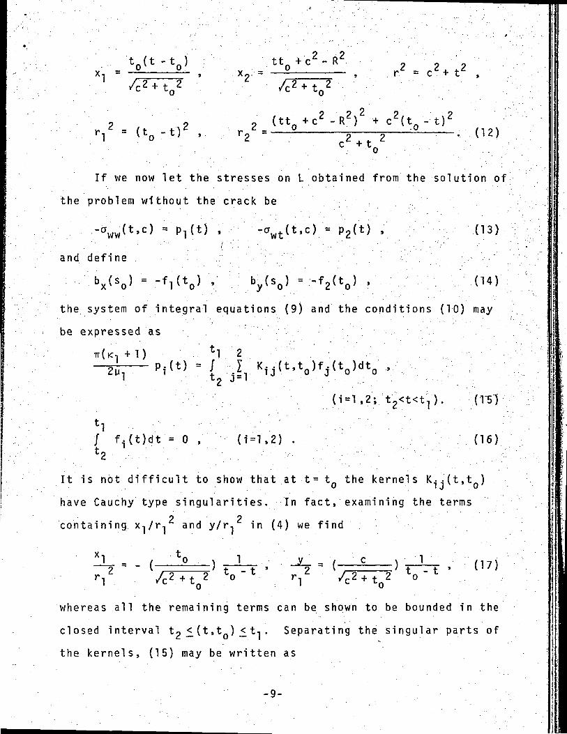
xl =9 ?t t 0 + c 2 - R 2
r =
= (t0--t)'
2 2c +v. ( 1 2 )
If we now let the stresses on L o b t a i n e d f rom the s o l u t i o n of
the p r o b l e m w i t h o u t the crack be
- a ww ( t ' c ) (13)
and define
bx(so} = "fl(to) • ' • • ' • by(so} = -W ' (14)
the system of integral equations (9) and the conditions (10) may
be expressed as
TT(K] +1) *1 2
1 t0 3=1
/ f.(t)dt = 0 ,_i_ I - - . •
1 = 1,2)' . (16)
It is not difficult to show that at t= tQ the kernels Kjj'U.t
have Cauchy type singularities. In fact, examining the terms2 2containing x-.fr-, and y/r, in (4) we find
, (17)
I
whereas all the remaining terms can be shown to be bounded in the
closed interval to £ (t ,t ) <_ t-, . Separating the singular parts of
the kernels, (15) may be written as
-9-
+D
2y- P l(t) =
TT(IC,
'1 .
. .P(t) =
Vt2 j
t]/ f2(t0) -*2 J
? f (t )
c dtoA. ±.
'cZ + t0Z °
*o dtoj- a.
c2+ t02 °
t dtQ
• k . T i ( t < t o > f T < . t o > d t <
t.
dt.
'2
-•*99(t.O.Mt'Jdtn vt
-22 0 . 2 0
(t2<t<t1), (18.a,b)
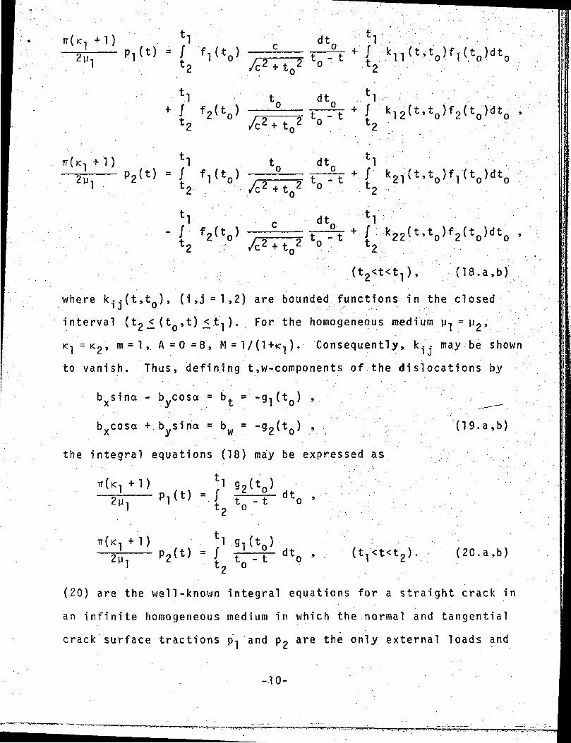
where k-.(t,t ), (i»j=l,2) are bounded functions in the closedJ " - . - - • • " ' : ' - • • ' • • • • ' : ' , '
interval (t2 (t ,t) _< t-,). For the homogeneous medium y, =yp,
K^ = <2»: m = 1 ,. A = 0 =B, M = 1/(1+K1). Consequently, k.- may be shown
to vanish. Thus, defining t,w-components of the dislocations by
bxsina - bycosa =
bxcosa + bysina =
(tQ) ,
(19.a,b)
the integral equations (18) may be expressed as
,2y 1
t]= / V (tT<t<t2) (20.a,b)
(20) are the well-known integral equations for a straight crack in
an infinite homogeneous medium in which the normal and tangential
crack surface tractions p, and p2 are the only external loads and
-10-
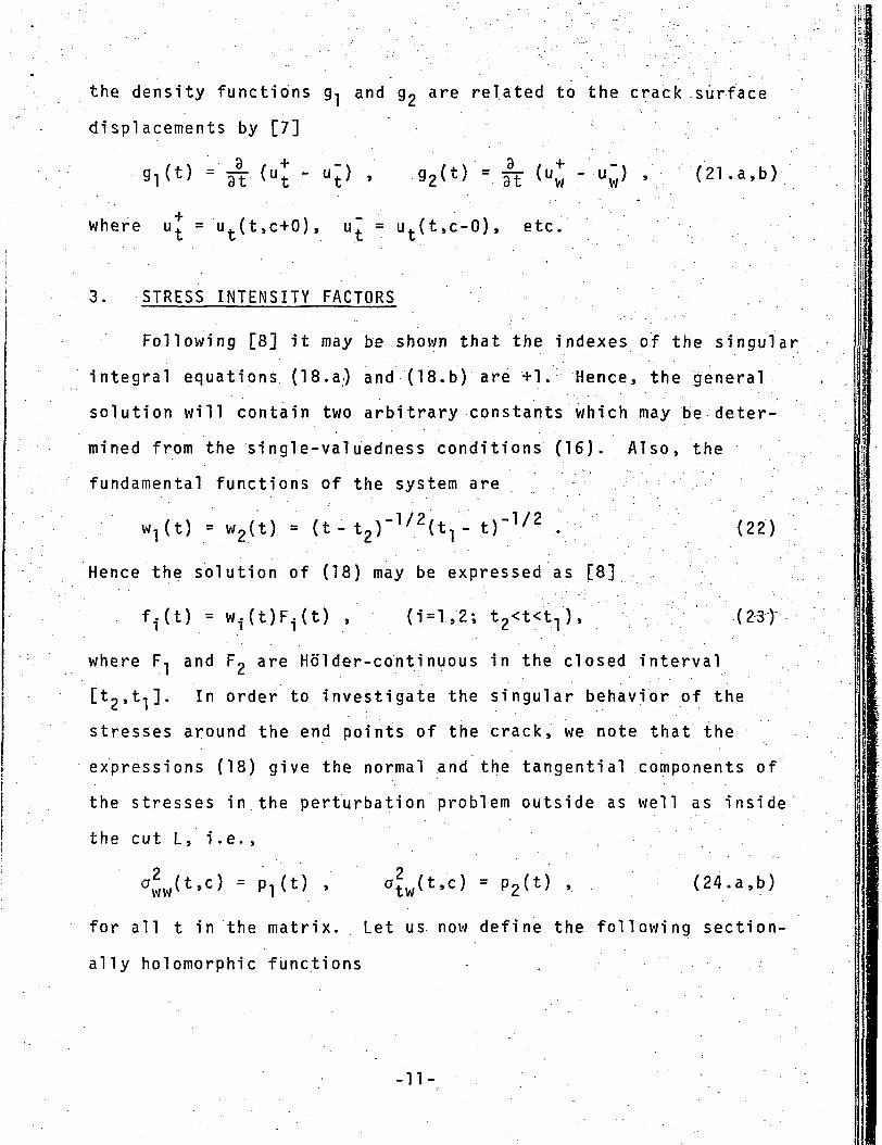
the density functions g-j and g2 are related to the crack surface
displacements by [7]
Mt} = 3T (ut " ut} ' 92(t) = It (uw " uw> ' (21-a,b)
where u^ ='ut(t,c+0), u~ = ut(t,c-0), etc.
3. STRESS INTENSITY FACTORS
Following [8] it may be shown that the indexes of the singular
integral equations (18. a) and (18. b) are +1. Hence, the general
solution will contain two arbitrary constants which may be deter-
mined from the single-valuedness conditions (16). Also, the
fundamental functions of the system are
w^t) = w2(t) = (t-t,,)-172^- t)"1/? . (22)
Hence the solution of (18) may be expressed as [8]
f^t) = w-UJF^t) , (i=l,2; t2<t<t1), (23)
where F-, and Fp are Holder-continuous in the closed interval
[tp,t,]. In order to investigate the singular behavior of the
stresses around the end points of the crack, we note that the
expressions (18) give the normal and the tangential components of
the stresses in the perturbation problem outside as well as inside
the cut L, i .e. ,
aww(t'c) = Pl(t) > atw(t'c) = P2(t) •- - (24. a, b)
for all t in the matrix. Let us now define the following section-
ally holomorphic functions . .
-11-
'*!- z dt.
; *Tdtn ,
( k , j = 1 ,2) ,
where
= ~a 22 a!2 = a21
(25)
( 2 6 )
Following [8] the asymptotic behavior of the Cauchy integral
(25) may be expressed as
' . - " ' • • • • : • - . . - ' • - . ; : • , ( 27 )1>s g e n e r a l l y b o u n d e d or at m o s t ha.s--where around t-, and
a singularity which is weaker than that of (z-t.)
<{)k.(z) is holomorphic outside the cut we may write
t
1 / 2" •' Since
I f1 I
1
*<>-•* dt0 =
(t, -t2)1/2(t2- t)
1/2
ak3(tl)F3(tl'T7?
- t)1/2(t-
(t<t2, (28)
From (18) and (28) it is seen that around the crack tips
t=t-| and t=t2 the stresses p-j and p2 will have the conventional
square-root singularity. If we now define the "stress intensity
-12-
factors" as follows:
= l im /2(t - t , ) - p j C t ) ,
MtJ = l im V 2 ( t - t j ) P 2 ( t ) ,'1
= lim /2(t2 - t) p^t) ,t->t2
= lim - t) p(t) ,' (29.a-d)
and let
a = (t2-
noting that
/ k i j ( t , t 0 ) f j ( t 0 ) d t 0 = f i n i t e , - ; ' ( - .«o<t<») ,
we fi nd
(30)
(31 )
'-1 Va(?7^
[cF1(t2) + t2F2(t2)]
- cF2(t2)] , (32.a-d)
where F, and F2 are the bounded functions defined by (23). It
should be obersved that if the transformation (19) is made before
-13-
solving the integral equations, repeating the foregoing analysis
or directly from (32) it is seen that in terms of the new unknown
functions g-j and g2 the stress intensity factors may be expressed
as2yi
kv(t,) = - lim , '• /2(t, - t) g«(t)1 1 t+t, ' + Kl ' ^
k2(t.,) = - Vim T-~- ^(ti - t) 9i(t)1
• ' • i _____ • ' ' . ' • ' • - ' • ' " - • -k , ( t 2 ) = l i r a Y-—^- ./2(t- t?) g ? ( t ) ,
1 * . . t->t2 ' +K1 i L -,
- • . ' • " 2U,: • _ _ . = ; • • . ' - . - . - • " • • • ' : - : ' - " . - • • • - . - ; " .k ? ( t « ) = lim 1-3-7- V 2 ( t - t2) g , ( t ) , (33 .a-d). z t-»t2 ' Kl z '
where g, and g2 are the derivatives of the crack surface displace-
ments (see (21 )).
4. NUMERICAL RESULTS _-- ;
Once the tractions p, and p« are specified, the system of
singular integral equations may be solved in a straightforward
manner (see [9] for an effective numerical technique). After
solving these equations, all the desired field quantities may be
evaluated by means of definite integrals with appropriate kernels
and f, and fp as the density functions. Since the main interest
in this paper is in the fracture of composite materials the numer-
ical results will be presented only for the stress intensity
factors defined by (29) and evaluated from (32). The results are
given for a uniaxial stress a at infinity (see the insert in
Figures 2-11). The calculated results are shown in Tables 1-7 and
-14-
Figures 2-11. The stress intensity factor ratios, k.., (i,j = l,2)- - " • • : ' . • . ' J • . . . •
shown in the tables and the figures are normalized with respect to
a /a" which is the stress intensity factor in a uniaxially stressed
infinite plane containing a crack of length 2a perpendicular to
the direction of loading. Thus
k., = 1 j , (i,j = 1,2) , .' (34)'" ' ' '
where k.(t.) is defined by (29). The length parameters a, b, c,' J • • . " • • • . • _ • . ,
and R are shown in the insert of Figures 2-11. In the numerical
analysis it is assumed that the crack is perpendicular to the
direction of external loading, a . Only two material combinations
have been considered. The first refers to a circular hole (i.e.,
y« = 0) and in the second it is assumed that
(y2/y-,) = 23 , K-, = 1.6 , <2 = 1.8 (35)
which roughly corresponds to a metallic inclusion imbedded into an
epoxy-type matrix. —""
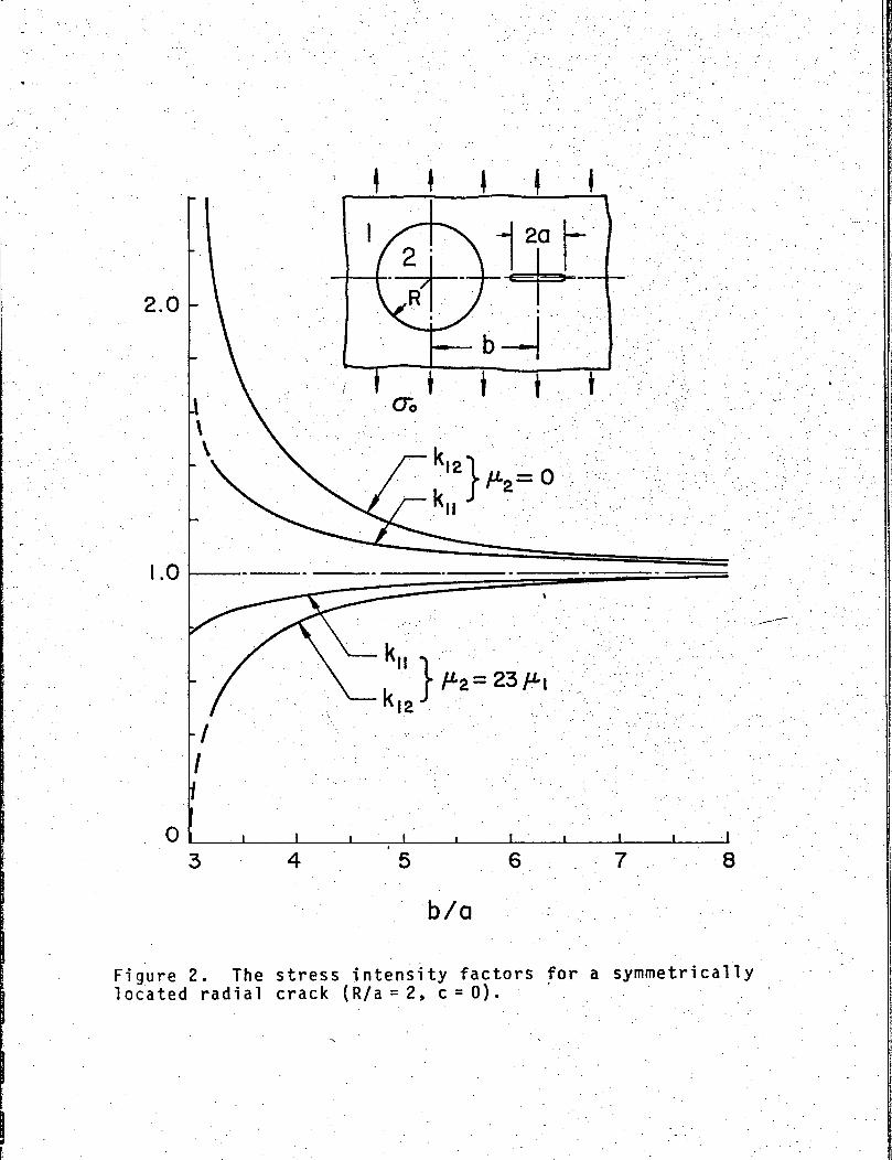
Table 1 and Figure 2 show the results for a radial crack. • • . , • \ - - " •
perpendicular to a . Note that as the crack tip t2 approaches the
hole k,p goes to infinity and as it approaches the inclusion-
matrix interface (where y2 > y-j ) k-]2 goes to zero. This problem
of a crack terminating at and going through the interface was
extensively studied in [10, 11, and 4]. It should also be noted
that for y2 = 0 and b/a = 3, k-j-j will be finite (see [4]).
-15-
2.0
.0
0
I '-I- I I I
I I I I j
8
b/d
Figure 2. The stress intensity factors for a symmetricallylocated radial crack (R/a= 2, c = 0).
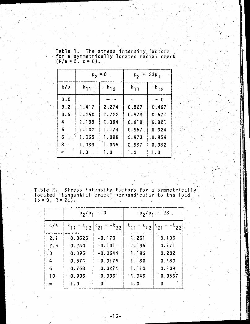
Table 1. The stress intensity factorsfor a symmetrically located radial crack(R/a = 2, c= 0).
b./a
3.0
3.2
3.5
4
5
6
800
V2 = °
kll
1.417
1.290
1.188
1.102
1.065
1.033
1.0
k!2
-> CO
2.2741.7221.3941.1741.0991.045
1.0
V2 = 23y r
k11
0.8270.8740.9180.9570.9730.9871.0
k!2
^ 0
0.4670.6710.8210.9240.9590.9821.0
Table 2. Stress intensity factors for a symmetricallylocated "tangential crack" perpendicular to the load(b= 0, R = 2a). ••-";
c/a
2.12.53461000
y2/y1 = o
kll = k!2
0.0626
0.260
0.395
0.574
0.768
0.9061.0
k21 =-k22
-0.170-0.101-0.0644-0.01750.02740.0361
y2/W1 = 23 .
kll = k!2
1.2011.196
1 .196
1.180
1.110
1.046
0 j 1.0
b ~ ~\fK21 K22
0.105
0.1710.2020.180
0.109
0.0567
0
-16-
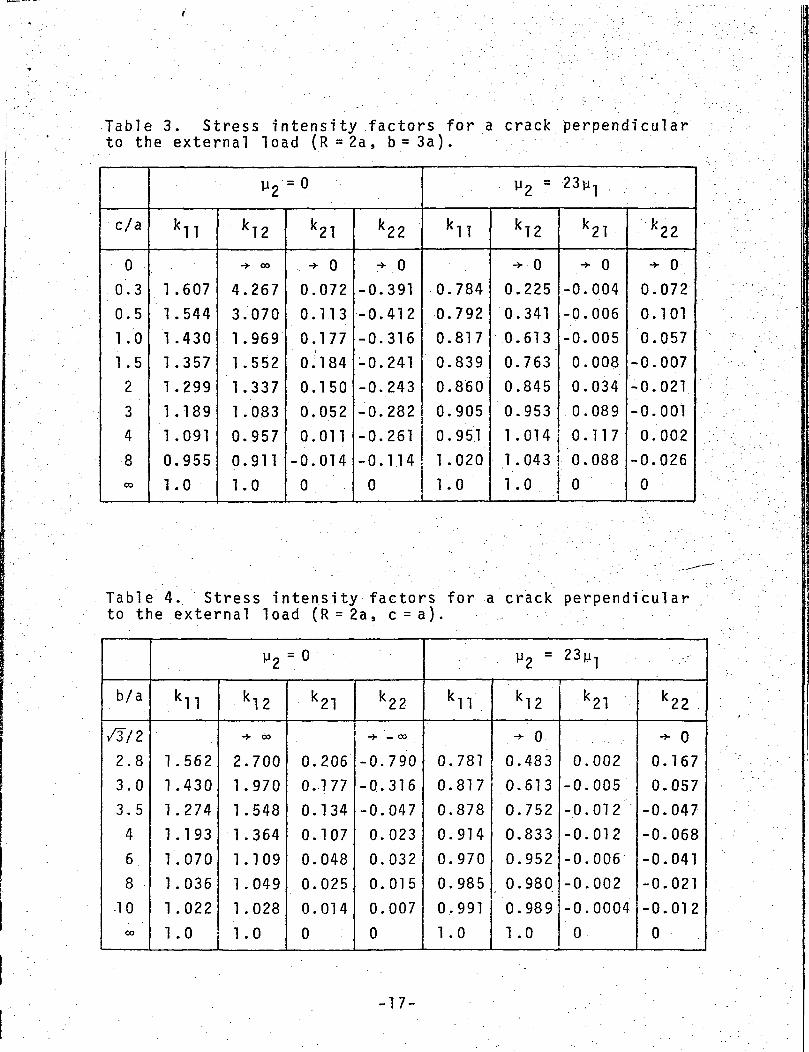
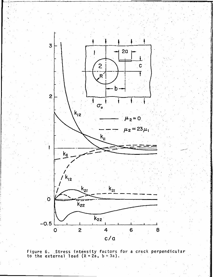
Table 3. Stress intensity factors for a crack perpendicularto the external load (R = 2a, b = 3a).
c/a
0
0.3
0.5
1.0
1.5
2
3
4
8CO
y 2 =0
kn
1.607
1.544
1.430
1.357
1.299
1.189
1.091
0.955
1.0
k!2
-> 00
4.267
3.070
1.969
1.552
1.337
1.083
0.957
0.911
1.0
k21
+ 0
0.072
0.113
0.177
0.184
0.150
0.052
0.011
-0.014
0
k22
+ 0
-0.391
-0.412
-0.316
-0.241
-0.243
-0.282
-0.261
-0.1.14
0
y2 = 23ia1
kll
0.784
0.792
0.817
0.839
0.860
0.905
0.951
1.020
1.0
k!2
-> 0
0.225
0.341
0.613
0.763
0.845
0.953
1.014
1.043
1.0
k21
.-" 0-0.004
-0.006
-0.005
0.008
0.034
0.089
0.117
0.088
0
k22
•*• °0.072
0.101
0.057
-0.007
-0.021
-0.001
0.002
-0.026
0
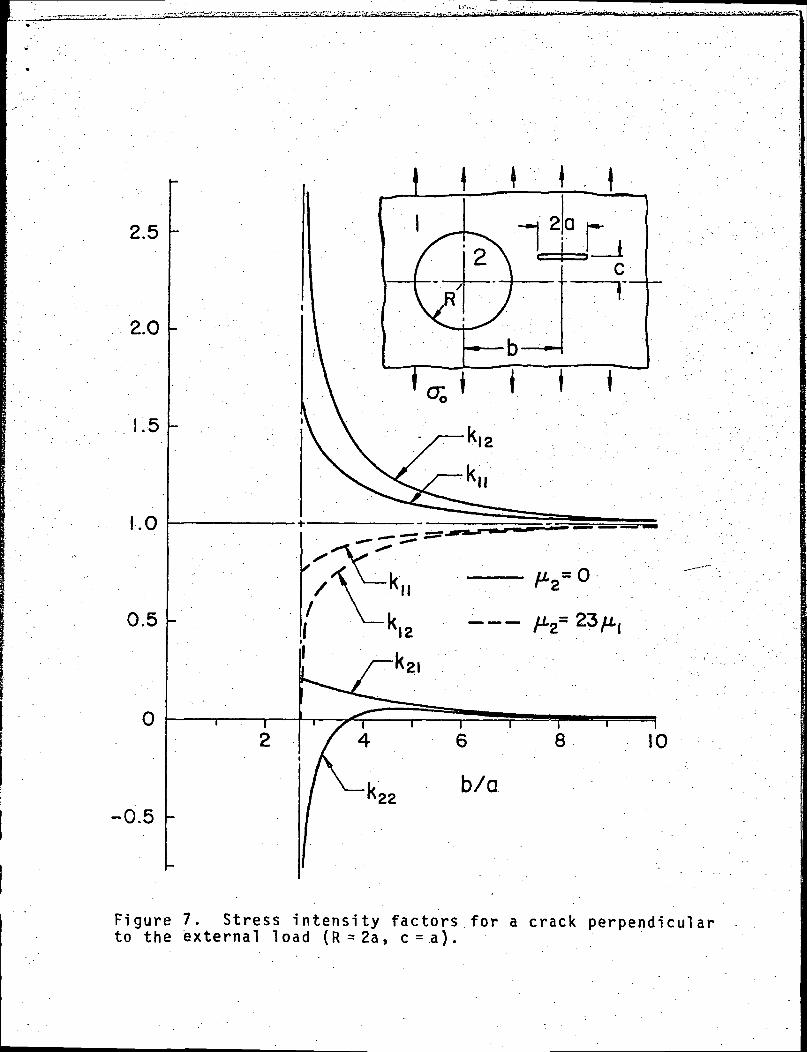
Table 4. Stress intensity factors for a crack perpendicularto the external load (R = 2a, c = a).
b/a
/3/2
2.8
3.0
3.5
4
6
8
10
CO
y2 = 0
kll
1.562
1.430
1.274
1.193
1.070
1.036
1.022
1.0
k!2
-> 00
2.700
1.970
1.548
1.364
1.109
1.049
1.028
1.0
k21
0.206
0.177
0.134
0.107
0.048
0.025
0.014
0
k22
->- -00
-0 .790
-0.316
-0.047
0.023
0.032
0.015
0.007
0
v2 = 23iji
kll
0.781
0.817
0.878
0.914
0.970
0.985
0.991
1.0
k !2
.-" 0
0.483
0.613
0.752
0.833
0.952
0.980
0.989
1.0
k21
0.002
-0.005
-0.012
-0.012
-0.006
-0.002
-0.0004
0
k22
-> 0
0.167
0.057
-0.047
-0.068
-0.041
-0.021
-0.012
0
-17-
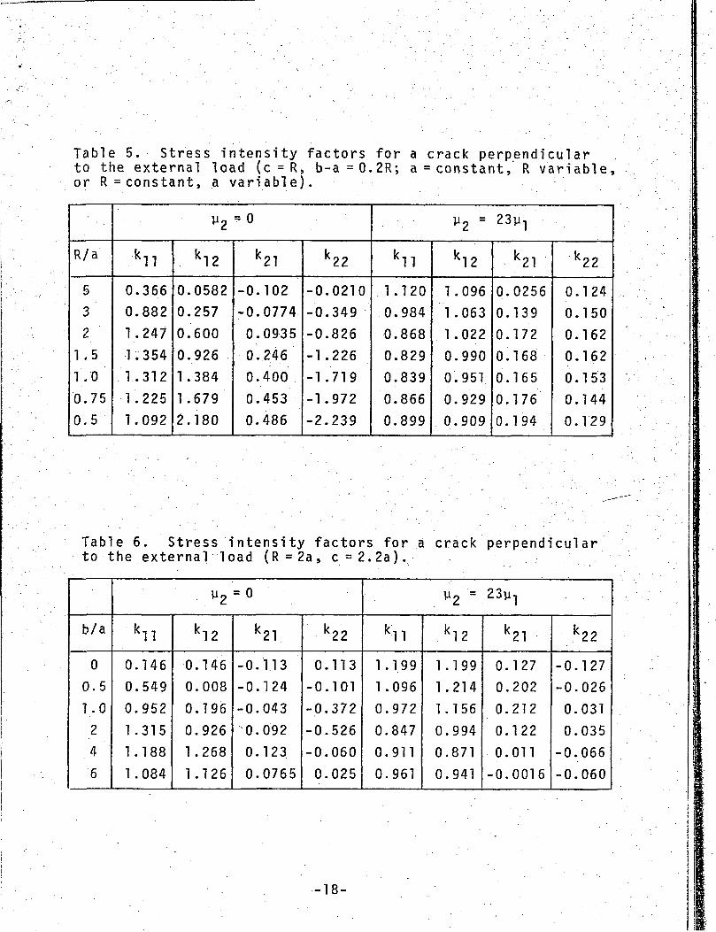
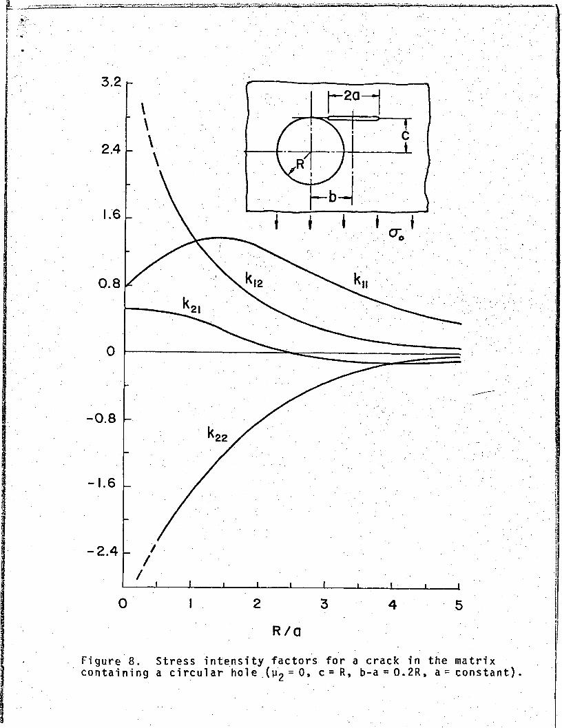
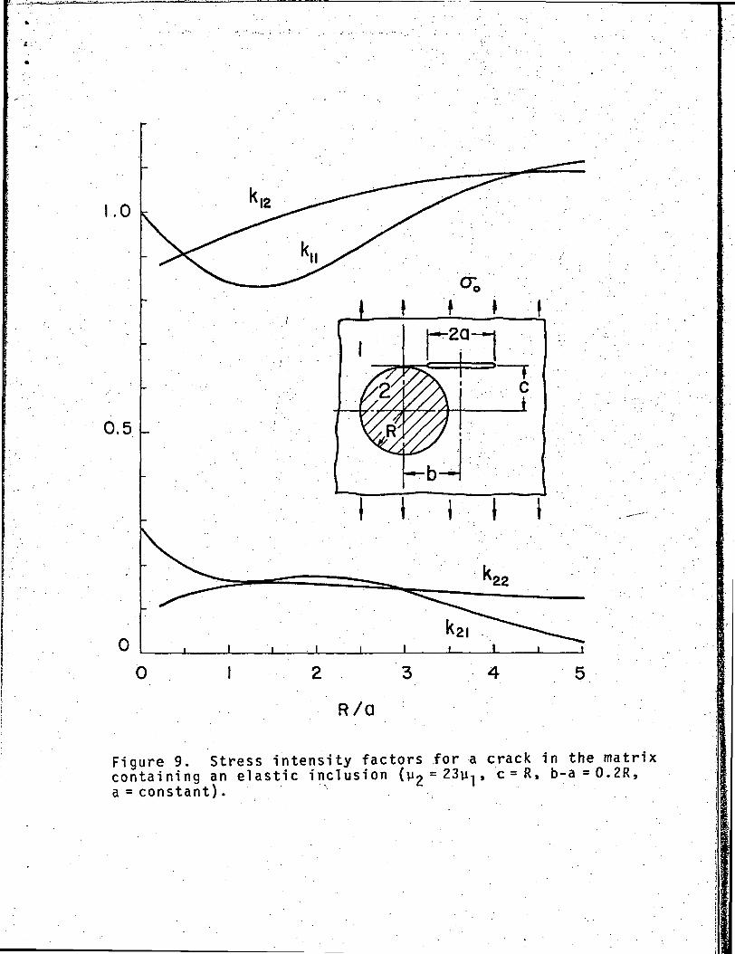
Table 5. Stress intensity factors for a crack perpendicularto the external load (c = R, b-a=0.2R; a =constant, R variable,or R= constant, a variable).
R/a
5
3
2
1.5
1.0
0.75
0.5
y2 = 0
kll
0.366
0.882
1.247
1.354
1.312
1.225
1.092
k!2
0.0582
0.257
0.600
0.926
1.384
1.679
2.180
k21
-0.102
-0.0774
0.0935
0.246
0.400
0.453
0.486
k22
-0.0210
-0.349
-0.826
-1.226
-1.719
-1.972
-2.239
y2 = 23y ]
kll
1.120
0.984
0.868
0.829
0.839
0.866
0.899
k!2
1.096
1 .063
1.022
0.990
0.951
0 . 929
0.909
k21
0.0256
0.139
0.172
0.168
0.165
0.176
0.194
k22
0.124
0.150
0.162
0.162
0.153
0.144
0.129
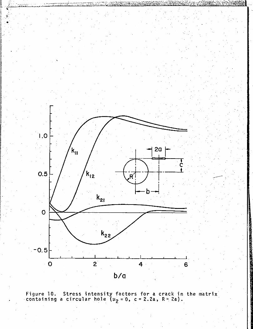
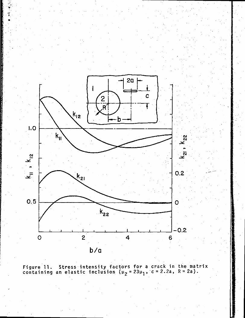
Table 6. Stress intensity factors for a crack perpendicularto the external load (R = 2a, c = 2.2a).
b/a
0
0.5
1.0
2
4
6
u2 = o
kll
0.146
0 .549
0.952
1.315
1.188
1.084
k!2
0.146
0.008
0.196
0.926
1.268
1.126
k21
-0.113
-0.124
-0.043
0.092
0.123
0 .0765
k22
0.113
-0.101
-0.372
-0.526
-0.060
0.025
U2 = 23ul
kll
1.199
1.096
0.972
0.847
0.911
0.961
k!2
1.199
1.214
1.156
0 .994
0.871
0.941
k21
0.127
0 .202
0.212
0.122
0.011
-0.0016
k22
-0.127
-0.026
0.031
0.035
-0.066
-0.060
-18-

Table 7. Stress intensity factors for a crackperpendicular to the external load (c=R/2).
" 2 ~ °
R/a
5
3
2
1.5
1.0
0.75
0.5
b/a
5.5
3.7
2.8
2.35
1.9
1.675
1.45
kll
1.866
1.721
1.562
1.448
1.309
1.232
1.153
k!2
2.426
2.668
2.862
2 . 993
3.139
3.185
3.120
U2 = 23u1
5
3
2
1.5
1.0
0.75
0.5
5.5
3.7
2.8
2 .35
1.9
1.675
1.45
0.654
0.716
0.781
0.827
0.881
0.911
0.940
0.508
0.483
0.469
0.463
0.460
0.464
0.481
k21
8.22xl(T4
0.148
0.206
0.217
0.205
0.188
0.165
k22
-0.816
-0.791
-0.727
-0.645
-0.472
-0.319
-0.0976
• • ..
0.050
0.010
0.002
0.008
0.026
0.040
0.056
0.025
0.178
0.156
0.139
0.113
0.094
0.062
-19-
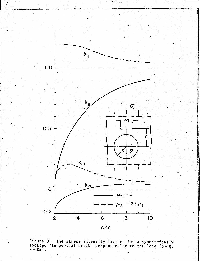
Table 2 and Figure 3 show the results for the other symmetric
crack geometry, namely, b=0 and c variable. In this case it is
seen that the stress intensity factor ratio k,, for the cleavage
mode may be greater than 1 for the stiffer inclusion and may be
considerably less than 1 for the hole. This and the similar
results observed in some of the subsequent figures may at first
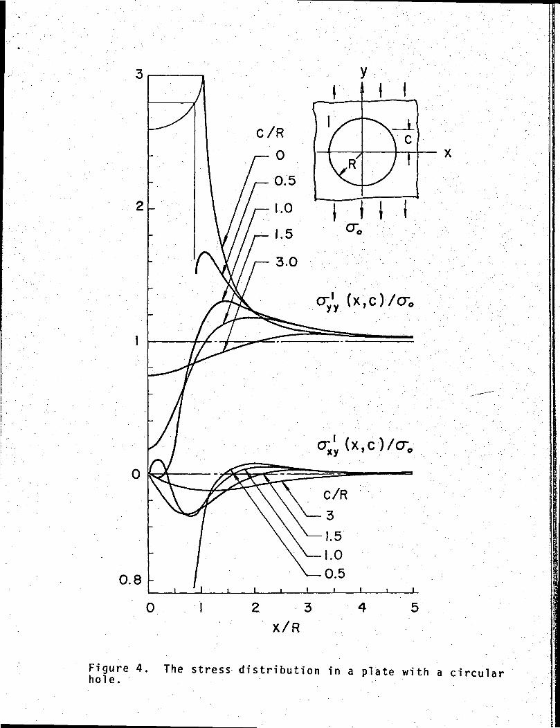
appear to be somewhat paradoxical. However, if one considers the
distribution of the stresses obtained from (1) in the absence of
the crack which is shown in Figures 4 and 5, the explanation for •
these trends would be clear. The stresses given in Figures 4 and
5 are related to the input functions in (1.8)' by .
pl(t) = ' ayy(t'c) »•'.'••• P2(t) = - axy(t'c) ' (36)
Other results which may be of interest in the applications
are given in Tables 3-7 and Figures 6-11. Since the shear compo-
nents, k2l-, (j=l,2) of the stress intensity factor are not zero",";.
in a brittle or quasi-brittle matrix the crack propagation would .
not be expected to be in the plane of the crack. From the results
given in this paper, it is not difficult to show that, generally
for the crack tip near the interface, the crack would propagate
towards the interface if n2 = 0 or V?< ^1 * an^ awa^ from it if
]jp > u-j . A quantitative model for this phenomenon was discussed
in [12]. ^ - . .
REFERENCES:
1. Isida, M., "On the Determination of Stress Intensity Factorsfor Some Common Structural Problems", J. Engng. FractureMechanics, Vol. 2, 1970, 'pp. 61-79. . .
2. Atkinson, C., "The Interaction Between a Crack and anInclusion", Int. J. Engng. Sci., Vol. 10, 1972, pp. 127-136.
-20- . i
3. Bhargava, R.D. and Bhargava, R.R., "Elastic'-Circular Inclu-sion in an Infinite Plane Containing Two Cracks", Int. J.Engng. Sci., Vol. 11, 1973, pp. 437-449. .
4. Erdogan, F. and Gupta, G.D., "The Inclusion Problem with aCrack Crossing the Boundary", NASA Project ReportNGR 39-007-011, March 1973.
5. Muskhelishvili, N.I., "Some Basic Problems of the Mathemati-cal Theory of Elasticity", P. Noordhoff Ltd., Groningen,Holland, 1953.
6. Dundurs, J. and Mura, T., "Interaction Between an EdgeDislocation and a Circular Inclusion", J. Mech. Phys.Solids, Vol. 12, 1964, pp. 177-189.
7. Erdogan, F. and Gupta, G.D., "Stress Analysis of Multi-Layered Composites with a Flaw", Int. J. Solids, Structures,Vol. 7, 1971 , pp. 39-61.
8. Muskhelishvili, N'. I., "Singular Integral Equations", P.Noordhoff Ltd., Groningen, Ho11 and, 1953.
9. Erdogan, F. and Gupta, G.D., "On the Numerical Solution ofSingular Integral Equations", Quarterly of Applied Mathemat-ics, Vol. 29, 1972, pp. 525-534.
10. Cook, T.S. and Erdogan, F., "Stresses in Bonded Materialswith a Crack Perpendicular to the Interface", Int. J. Engng.Sci., Vol. 10, 1972, pp. 667-697.
11. Erdogan, F. and Biricikoglu, V., "Two Bonded Half Planeswith a Crack Going Through the Interface", Int. J. Engng.Sci., 1973 (to appear).
12. Erdogan, F. and Sih, G.C., "On the Crack Extension in PlatesUnder Plane Loading and Transverse Shear", J. Basic Engng.,Trans. ASME, Vol. 85, Series D, 1963, pp. 519-526.
-21-
1.0
0.5
-0.24 6
c/a
8 10
Figure 3. The stress intensity factors for a symmetricallylocated "tangential crack" perpendicular to the load (b=0,R = 2a).
cr1 (X,C)/CT;
o
Figure 4. The stress distribution in a plate with a circularhoi e.

C/R
(x,c)/cr0
cr lx,c)/p-"7
X /R
Figure 5. The stress distribution in a plate with a circulare last ic inclusion (^2 = 23y- j , K - j = 1 . 6 , K2
= 1 - 8 ) .
-0.54
c/a8
Figure 6. Stress intensity factors for a crack perpendicularto the external load (R = 2a, b = 3a).
LJ_J
-0.5 h
Figure 7. Stress intensity factors for a crack perpendicularto the external load (R = 2a, c = a).
-0.8 r-
-1.6 L
0
R/a
Figure's. Stress intensity factors for a crack in the matrixcontaining a circular hole .(u2 = °> c = R, b-a = 0.2R, a = constant)
1.0
0.5
I I I
R/d
F i g u r e 9. Stress intensi ty factors for a crack in the matr ixc o n t a i n i n g a n e las t ic i n c l u s i o n ( y 2
= 23V!-j» c = R » b - a = 0 . 2 R ,a = cons t an t ) . ,
b/a
Figure 10. Stress intensity factors for a crack in the matrixcontaining a circular hole (y2 = 0, c=2.2a, R=2a).
*-.•' *'. •
1,0
0.5
COeg
0.2
-0.2
b/a
Figure 11. Stress intensity factors for a crack in the matrixcontaining an elastic inclusion (y2 = 23y-j, c = 2.2a, R = 2a).