Embed Size (px)
Citation preview

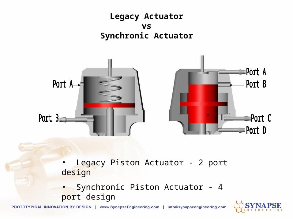
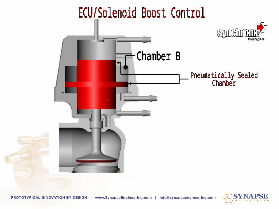
• Legacy Piston Actuator - 2 port design
• Synchronic Piston Actuator - 4 port design
Legacy Actuatorvs
Synchronic Actuator
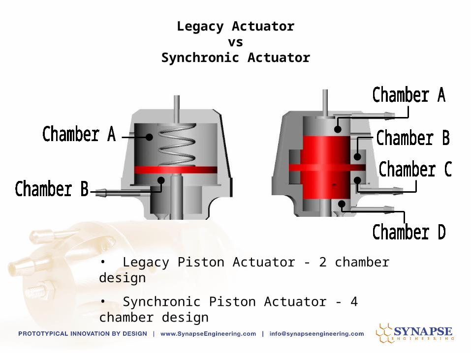
• Legacy Piston Actuator - 2 chamber design
• Synchronic Piston Actuator - 4 chamber design
Legacy Actuatorvs
Synchronic Actuator
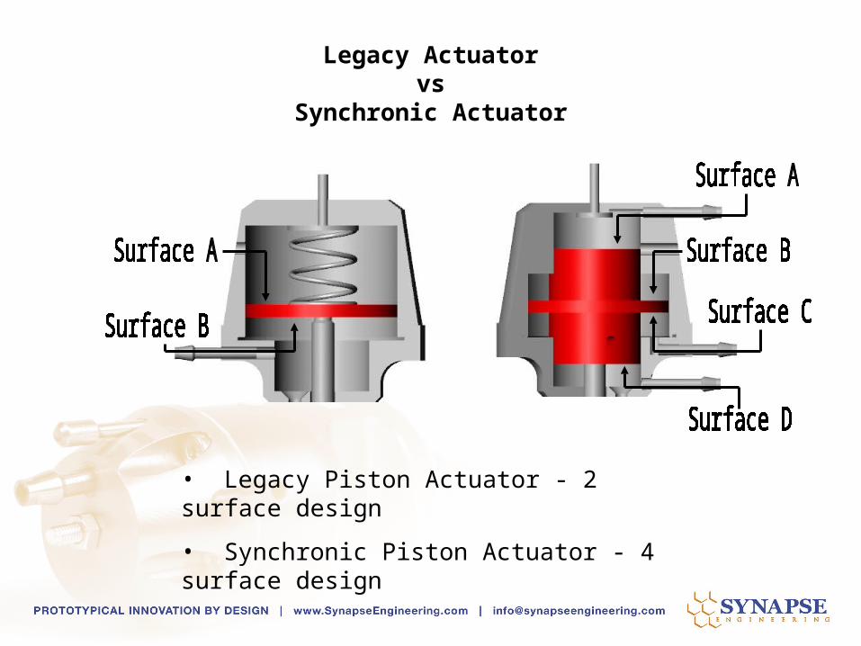
• Legacy Piston Actuator - 2 surface design
• Synchronic Piston Actuator - 4 surface design
Legacy Actuatorvs
Synchronic Actuator

• Pressure to each port & chamber acts on their respective surface area.
• The force produced by the pressure depends on the surface area
Legacy Actuatorvs
Synchronic Actuator

Unlike the legacy actuator, the Synchronic actuator geometry is a self centering geometry
under pressure
Legacy Actuatorvs
Synchronic Actuator

Spring Pre-Load
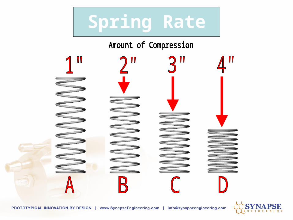
Spring Rate

Spring Rate


•Flexible Diaphragm Actuator
•Unequal Actuation Surface Areas
•1 Axis for Valve Guiding
•2-Port, 2-Chamber, 2-Surface Actuator
•Spring-Biased

•Billet Aluminum Piston Actuator
•Ratiometric Actuation Surface Areas
•4 Axes for Valve Guiding
•4-Port, 4-Chamber, 4-Surface Actuator Design
•Spring-Biased

•Diaphragms can tear
•Diaphragm durometer changes with temperature
•Could get harder or softer
•Stretchability is variable
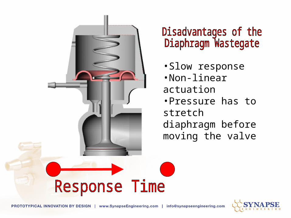
•Slow response•Non-linear actuation•Pressure has to stretch diaphragm before moving the valve

•You can only adjust spring pre-load•You cannot reap the benefits of adjusting spring rate
•No control of the valve’s rising rate ratio per pound of boost
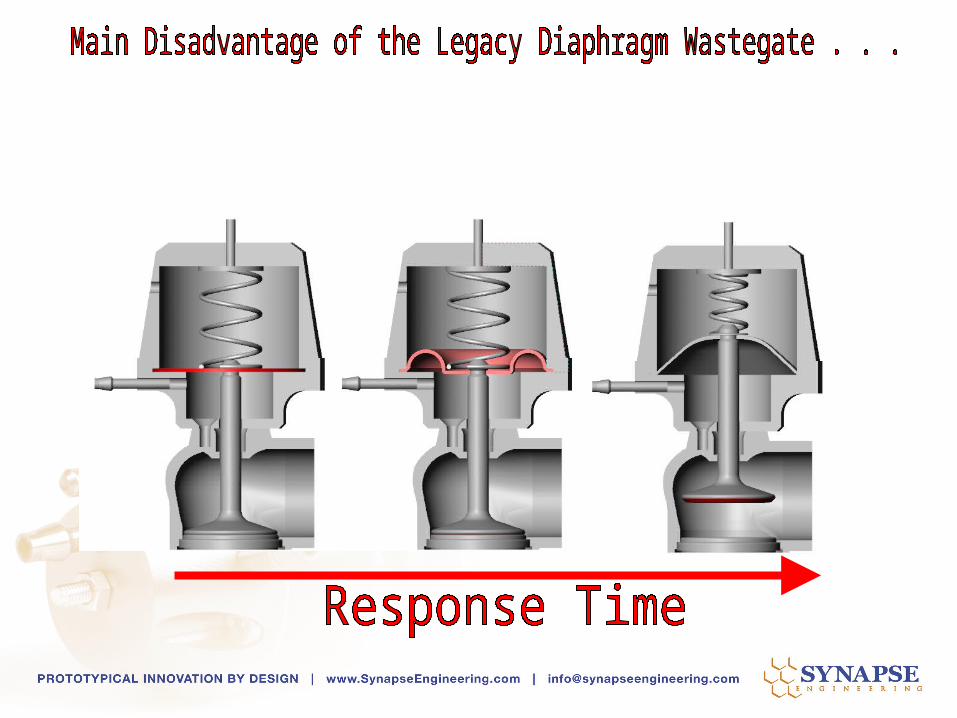

Pressure is wasted on stretching the diaphragm before acting on the valve

While the legacy diaphragm WG stretches the diaphragm,Synchronic Wastegate has already lifted the valve

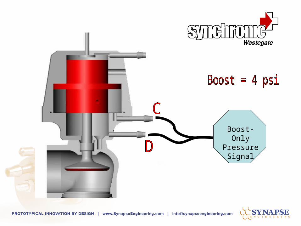
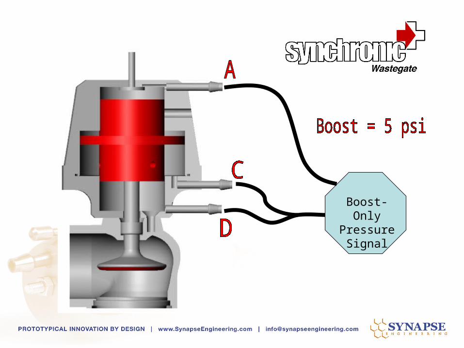
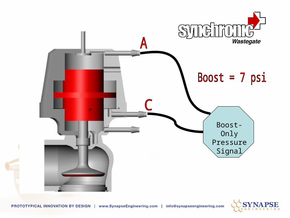
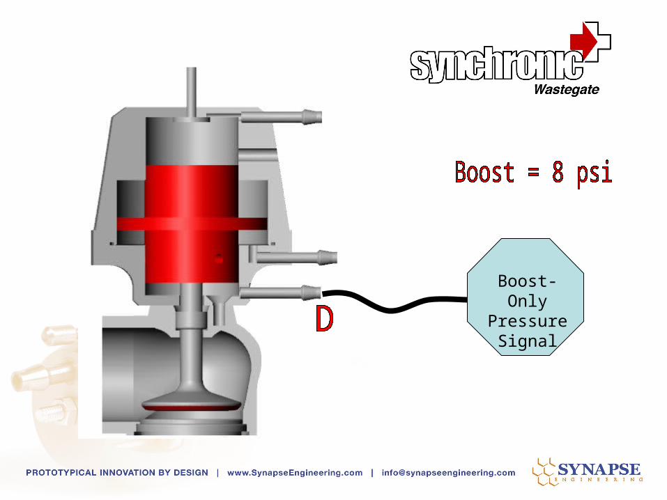
Boost-Only Pressure
Signal
5 psi
With Synchronic Wastegate spring rate can be changed with the same pre-load, to change the amount of valve lift per pound of boost

The legacy wastegate only allows adjustment of spring pre-load to control when the wastegate
opens and the resultant boost level.

Spring rate cannot be increased independent of pre-load. Higher boost is achieved with a combination of increase pre-load and rate.
Spring Rate = 25 lbs./in.
Spring Rate = 25 lbs./in.
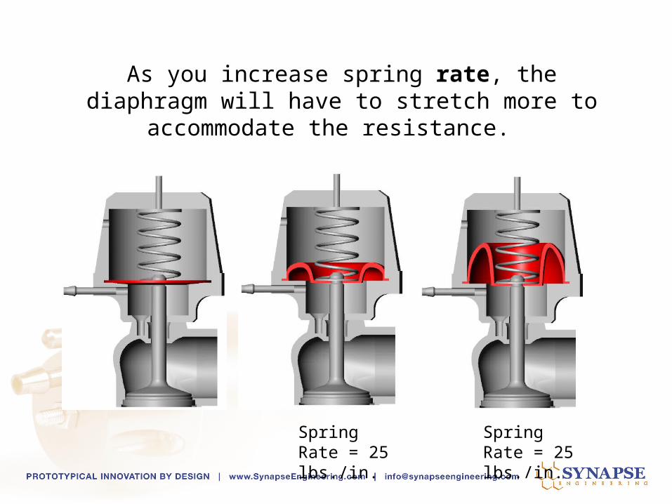
As you increase spring rate, the diaphragm will have to stretch more to accommodate the
resistance.
Spring Rate = 25 lbs./in.
Spring Rate = 25 lbs./in.
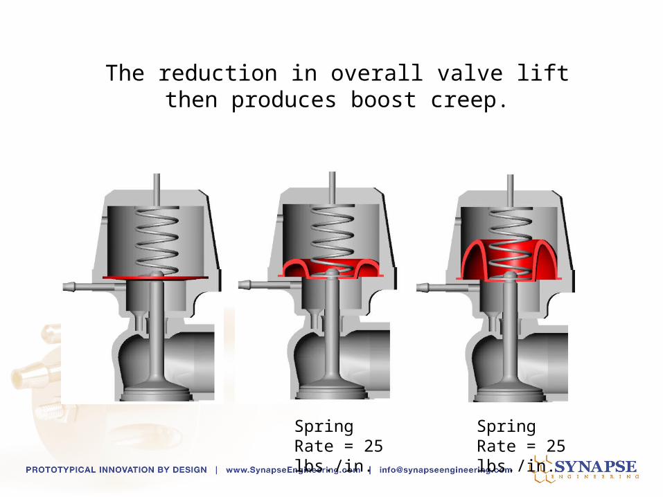
The reduction in overall valve lift then produces boost creep.
Spring Rate = 25 lbs./in.
Spring Rate = 25 lbs./in.

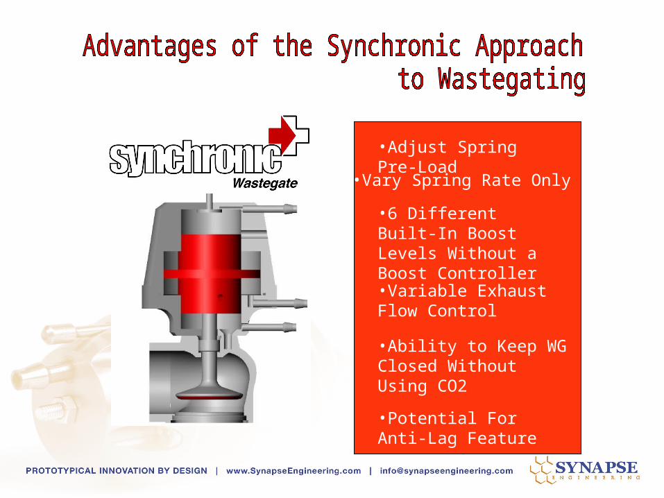
•Adjust Spring Pre-Load

•Adjust Spring Pre-Load
•Vary Spring Rate Only

•Adjust Spring Pre-Load
•Vary Spring Rate Only
•6 Different Built-In Boost Levels Without a Boost Controller

•Adjust Spring Pre-Load
•Vary Spring Rate Only
•6 Different Built-In Boost Levels Without a Boost Controller
•Variable Exhaust Flow Control

•Adjust Spring Pre-Load
•Vary Spring Rate Only
•6 Different Built-In Boost Levels Without a Boost Controller
•Ability to Keep WG Closed Without Using CO2
•Variable Exhaust Flow Control
•Adjust Spring Pre-Load
•Vary Spring Rate Only
•6 Different Built-In Boost Levels Without a Boost Controller
•Ability to Keep WG Closed Without Using CO2
•Potential For Anti-Lag Feature
•Variable Exhaust Flow Control
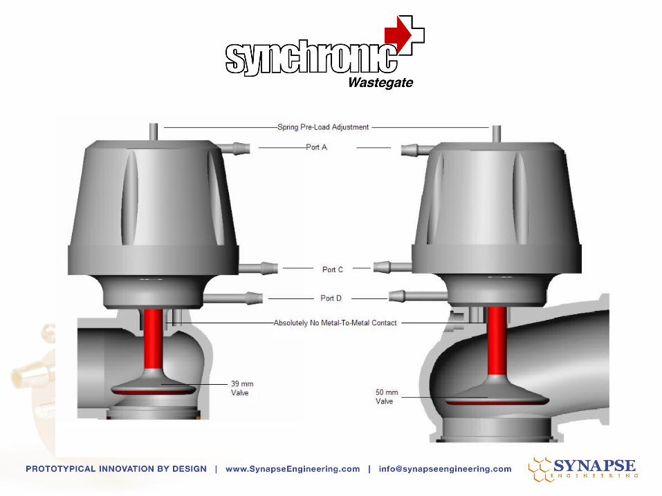


Boost Signal to Port C&D, 36 mm Valve Seat, Pre-Load Adjustments
0
50
100
150
200
250
300
1950
2150
2350
2550
2750
2950
3150
3350
3550
3750
3950
4150
4350
4550
4750
4950
5150
5350
5550
5750
5950
6150
6350
6550
6750
6950
7150
7350
7550
7750
7950
8150
8350
8550
8750
RPM
HP
0
0.5
1
1.5
2
2.5
3
3.5
4
4.5
5
Boos
HP 36 mmC&D
HP PL 1
Torque Pre-Load
Torque 36 mm
36 mm C+D
Pre-Load 1

Boost-Only Pressure
Signal
Boost-Only Pressure
Signal

Boost-Only Pressure
Signal
Boost-Only Pressure
Signal
Boost-Only Pressure
Signal

Boost-Only Pressure
Signal


Boost Pressure Settings
0
1
2
3
4
5
6
7
8
1821
2000
2200
2400
2600
2800
3000
3200
3400
3600
3800
4000
4200
4400
4600
4800
5000
5200
5400
5600
5800
6000
6200
6400
6600
6800
7000
7200
7400
7600
7800
8000
8200
8400
8600
8800
RPM
36 mm D
36 mm C+A
36 mm C
36 mm C+D+A
36 mm C+D

Boost Settings HP Results
0
50
100
150
200
250
300
350
1821
2000
2200
2400
2600
2800
3000
3200
3400
3600
3800
4000
4200
4400
4600
4800
5000
5200
5400
5600
5800
6000
6200
6400
6600
6800
7000
7200
7400
7600
7800
8000
8200
8400
8600
8800
36 mm D
36 mm C+A
36 mm C
36 mm C+D+A
36 mm C+D

Different size valve seats allow for fine tuning of
flow and performance
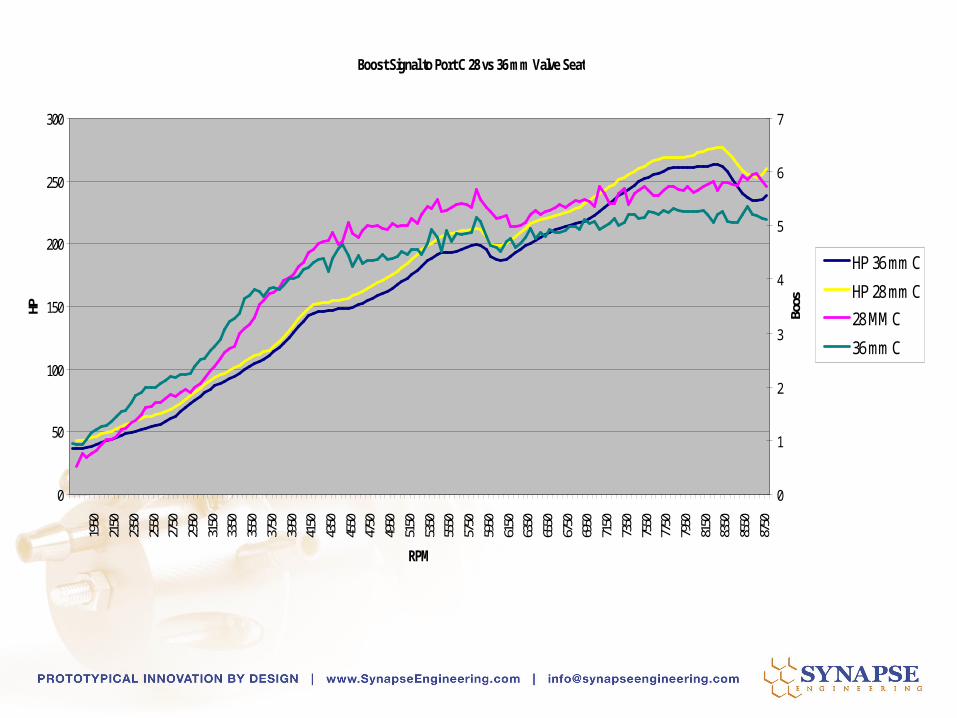
Boost Signal to Port C 28 vs 36 mm Valve Seat
0
50
100
150
200
250
300
1950
2150
2350
2550
2750
2950
3150
3350
3550
3750
3950
4150
4350
4550
4750
4950
5150
5350
5550
5750
5950
6150
6350
6550
6750
6950
7150
7350
7550
7750
7950
8150
8350
8550
8750
RPM
HP
0
1
2
3
4
5
6
7
Boos
HP 36 mm C
HP 28 mm C
28 MM C
36 mm C

Boost Signal to Port D 28 vs 36 mm Valve Seat
0
50
100
150
200
250
300
350
1950
2150
2350
2550
2750
2950
3150
3350
3550
3750
3950
4150
4350
4550
4750
4950
5150
5350
5550
5750
5950
6150
6350
6550
6750
6950
7150
7350
7550
7750
7950
8150
8350
8550
8750
RPM
HP
0
1
2
3
4
5
6
7
8
Boos
HP 36 mm D
HP 28 mm D
28 MM D
36 mm D
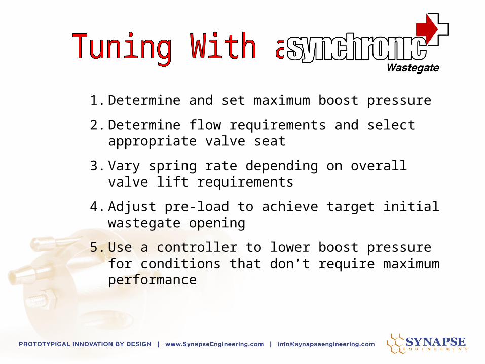
1. Determine and set maximum boost pressure
2. Determine flow requirements and select appropriate valve seat
3. Vary spring rate depending on overall valve lift requirements
4. Adjust pre-load to achieve target initial wastegate opening
5. Use a controller to lower boost pressure for conditions that don’t require maximum performance

Boost-Only Pressure
Signal
Solenoid
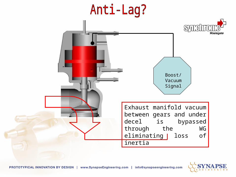
Boost/VacuumSignal
Exhaust manifold vacuum between gears and under decel is bypassed through the WG eliminating loss of inertia