Embed Size (px)
Citation preview

Lecture Notes
On
BEE 1711 POWER SYSTEM-III
A COURSE IN 7TH SEMESTER OF BACHELOR OF TECHNOLOGY PROGRAMME IN ELECTRICAL AND ELECTRONICS ENGINEERING
Department of Electrical & EEE Engineering
Veer Surendra Sai Institute of Technology, Burla,
Sambalpur- 768018

DISCLAIMER
This document does not claim any originality and cannot be used as a substitute
for prescribed textbooks. The matter presented here is prepared by the author for
their respective teaching assignments by referring the text books and reference
books. Further, this document is not intended to be used for commercial purpose
and the committee members are not accountable for any issues, legal or
otherwise, arising out of use of this document.

BEE 1711 POWER SYSTEM-III
Lecture Plan
Module No. Lecture
No. Topics
MODULE – I
1. Philosophy of protection, Nature, Causes and consequences of faults,
Zone of protection, Requirements of a protective scheme, Basic
terminology components of protection scheme.
2. Circuit Breakers: Formation of arc during circuit breaking.
3. Theories of arc Interruption.
4. Recovery and restriking voltage, interruption of capacitive and
inductive currents.
5. Current chopping, circuit breaker rating, Different types of circuit
breakers.
6. Air break and Air blast circuit breaker.
7. Plain break and controlled break all circuit breakers.
8. Minimum oil circuit breakers.
9. Vacuum circuit breaker
10. SF6circuit breaker. D.C. Circuit breaker
MODULE – II
11. Relay classification, Principle of different types of electromagnetic
relay.
12. General equation of phase and magnitude comparators, Duality of
comparators,
13. Electromagnetic relays
14. , over current relays Directional relays,
15. Distance relay- impedance,
16. Reactance and Mho type, Differential relays,
17. Concept of static and numerical relay.
18. Feeder Protection, Generator Protection,
19. Transformer Protection,
20. Bus Zone Protection
MODULE – III
21. Z bus Algorithm,
22. Z bus Algorithm,
23. Z bus Algorithm,
24. Symmetrical and unsymmetrical fault analysis for power system,
25. Symmetrical and unsymmetrical fault analysis for power system,
26. Symmetrical and unsymmetrical fault analysis for power system,
27. Z bus method in fault analysis.
28. Arrangement of Bus bar,
29. Arrangement of Circuit breaker and isolator.
30. Current limiting reactors in power system and their arrangement
calculation of fault MVA for symmetrical short circuits. Circuit
breaker capacity.
MODULE – IV
31. Power System Stability,
32. Power System Stability,
33. Steady State Stability, Transient stability,
34. Swing equation, Equal area criterion for stability,
35. Swing equation, Equal area criterion for stability,
36. Critical clearing angle,
37. point by point Methods of improvement of transient stability.
38. point by point Methods of improvement of transient stability.
39. Voltage stability, concept, causes and counter measures.
40. Load frequency control, PF versus QV control
Books:
[1]. Van C Warrington, “Protective Relays” Vol.-I & II
[2]. Ravindranath, M.Chander, “Power System Protection and SwitchGear”, Wiley Eastern
Ltd. New Delhi.
[3]. John J Grainger, W. D. Stevenson, “Power System Analysis”, TMH Publication
[4]. P. Kundur, “Power System Stability and Control”, TMH Publication
MODULE- I
Philosophy of Protection
The purpose of an Electric Power System is to generate and supply electrical energy to
consumers. The power system should be designed and managed to deliver this energy to the
utilization points with both reliability and economically
The capital investment involved in power system for the generation, transmission and
distribution is so great that the proper precautions must be taken to ensure that the equipment not
only operates as nearly as possible to peak efficiency, but also must be protected from accidents
The normal path of the electric current is from the power source through copper (or aluminium)
conductors in generators, transformers and transmission lines to the load and it is confined to this
path by insulation.
Nature of Faults
Short circuit fault- current
Open circuit fault- voltage
In terms of seriousness of consequences of a fault, short circuits are of far greater concern
than open circuits, although some open circuits present some potential hazards to personnel
Classification of short circuited Faults
• Three phase faults (with or without earth connection)
• Two phase faults (with or without earth connection)
• Single phase to earth faults
Classification of Open Circuit Faults
• Single Phase open Circuit
• Two phase open circuit
• Three phase open circuit
Causes of Faults
The insulation, however, may break down, either by the effect of temperature and age or by a
physical accident, so that the current then follows an abnormal path generally known as Short
Circuit or Fault
• Any abnormal operating state of a power system is known as FAULT.
• A fault in general consists of short circuits as well as open circuits.
• Open circuit faults are less frequent than short circuit faults, and often they are
transformed in to short circuits by subsequent event
Consequences of occurrence of Faults
• Expensive damage to the equipment due to abnormally large currents, unbalanced
currents, or low voltages produced by the short circuits
• Explosions which may occur in equipment containing insulating oil during short circuits
and which may cause fire resulting in serious hazard to personnel and to other equipment
• Sever drop in voltage which is likely to cause the individual generators in a power
station or a group of generators in different stations to loose synchronism and fall out of
step with consequent splitting of the system
• A risk of synchronous motors in large industrial premises falling out of step and tripping
out.
Zones of Protection
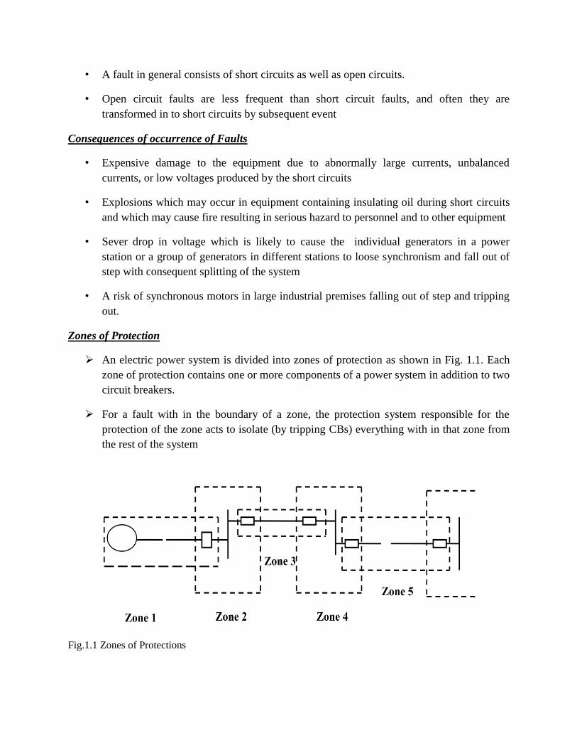
An electric power system is divided into zones of protection as shown in Fig. 1.1. Each
zone of protection contains one or more components of a power system in addition to two
circuit breakers.
For a fault with in the boundary of a zone, the protection system responsible for the
protection of the zone acts to isolate (by tripping CBs) everything with in that zone from
the rest of the system
Fig.1.1 Zones of Protections

The circuit Breakers are inserted between the component of of the zone and the rest of the
power system. Thus, the location of the CBs helps to define the boundaries of the zones
of protection.
The neighbouring zones of protection are made to overlap so as to ensure that no part of
the power system remains without protection. However, occurrence of fault with in the
overlapped region would trip more number of circuit breakers than the minimum
necessary to disconnect the faulty element
Protection System Requirements
• The fundamental requirements for a protection system areas follows:
– Reliability: the ability of the protection to operate correctly. It has two basic
elements-dependability, which is the certainty of a correct operation on the
occurrence of a fault, and security ,which is the ability to avoid incorrect
operation during faults.
– Speed: minimum operating time to clear a fault in order to avoid damage to
equipment.
– Selectivity: maintaining continuity of supply by disconnecting the minimum
section of the network necessary to isolate the fault. The property of selective
tripping is also called ”discrimination” and is achieved by two general methods:
• Time graded systems
• Unit systems
– Cost: maximum protection at the lowest cost possible
Primary and back-up Protection
• Primary Protection
– The primary protection scheme ensures quick and selective clearing of the faults
within the boundary of the circuit element it protects. Primary Protection as a
rule is provided for each section of an electrical installation.
Causes of Failure of Primary Protection
Primary Protection may fail because of failure in any of the following:
1. Current or voltage supply to the relay.
2. D.C.tripping voltage supply
3. Protective relays
4. Tripping circuit
5. Circuit Breaker
• Back-up Protection
Back-up protection is the name given to a protection which backs the primary protection
whenever the later fails in operation.
The back-up protection by definition is slower than the protection
The design of the back-up protection needs to be coordinated with the design of the
primary protection
Circuit Breaker
Circuit breakers provide a manual means of energizing and de-energizing a circuit and
automatic over current protection. Unlike fuses, which must be replaced when they open, a
circuit breaker can be reset once the over current condition has been corrected. Pushing the
handle to the “OFF” position then back to the “ON” position restores the circuit. If a circuit
reopens upon reset to the “ON” position, the circuit should be checked by a qualified electrician.
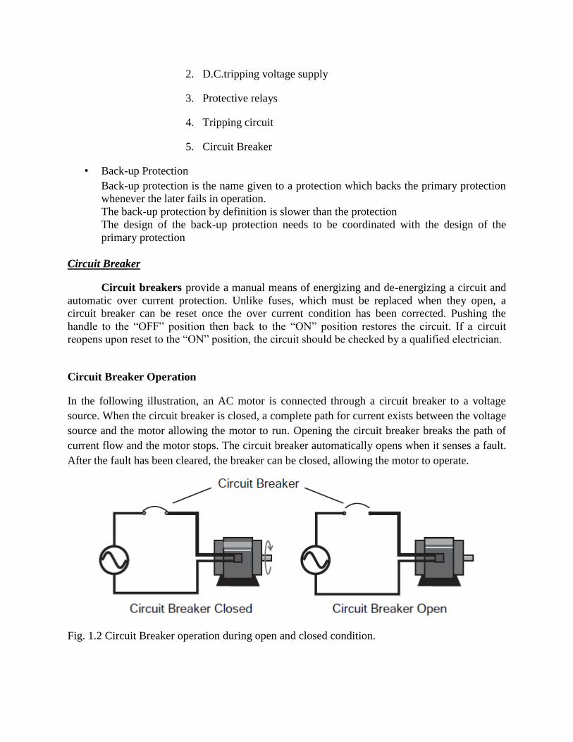
Circuit Breaker Operation
In the following illustration, an AC motor is connected through a circuit breaker to a voltage
source. When the circuit breaker is closed, a complete path for current exists between the voltage
source and the motor allowing the motor to run. Opening the circuit breaker breaks the path of
current flow and the motor stops. The circuit breaker automatically opens when it senses a fault.
After the fault has been cleared, the breaker can be closed, allowing the motor to operate.
Fig. 1.2 Circuit Breaker operation during open and closed condition.
Formation of arc during circuit breaking
During opening of current carrying contacts in a circuit breaker the medium in between
opening contacts become highly ionized through which the interrupting current gets low resistive
path and continues to flow through this path even the contacts are physically separated. During
the flowing of current from one contact to other the path becomes so heated that it glows. This is
called arc.
Arc in Circuit Breaker
Whenever, on load current contacts of circuit breaker open there is an arc in circuit breaker,
established between the separating contacts. As long as this arc is sustained in between the
contacts the current through the circuit breaker will not be interrupted finally as because arc is
itself a conductive path of electricity. For total interruption of current the circuit breaker it is
essential to quench the arc as quick as possible. The main designing criteria of a circuit breaker is
to provide appropriate technology of arc quenching in circuit breaker to fulfill quick and
safe current interruption. So before going through different arc quenching techniques employed
in circuit breaker, we should try to understand "e;what is arc"e; and basic theory of arc in circuit
breaker, let‟s discuss.
Thermal Ionization of Gas
There are numbers of free electrons and ions present in a gas at room temperature due to
ultraviolet rays, cosmic rays and radioactivity of the earth. These free electrons and ions are so
few in number that they are insufficient to sustain conduction of electricity. The gas molecules
move randomly at room temperature. It is found an air molecule at a temperature of 300°K
(Room temperature) moves randomly with an approximate average velocity of 500
meters/second and collides other molecules at a rate of 1010
times/second. These randomly
moving molecules collide each other in very frequent manner but the kinetic energy of the
molecules is not sufficient to extract an electron from atoms of the molecules. If the temperature
is increased the air will be heated up and consequently the velocity on the molecules increased.
Higher velocity means higher impact during inter molecular collision. During this situation some
of the molecules are disassociated in to atoms. If temperature of the air is further increased many
atoms are deprived of valence electrons and make the gas ionized. Then this ionized gas can
conduct electricity because of sufficient free electrons. This condition of any gas or air is called
plasma. This phenomenon is called thermal ionization of gas.
Ionization due to Electron Collision
As we discussed that there are always some free electrons and ions presents in the air or gas but
they are insufficient to conduct electricity. Whenever these free electrons come across a strong
electric field, these are directed towards higher potential points in the field and acquire
sufficiently high velocity. In other words, the electrons are accelerated along the direction of the
electric field due to high potential gradient. During their travel these electrons collide with other
atoms and molecules of the air or gas and extract valance electrons from their orbits. After
extracted from parent atoms, the electrons will also run along the direction of the same electric
field due to potential gradient. These electrons will similarly collide with other atoms and create
more free electrons which will also be directed along the electric field. Due to this conjugative
action the numbers of free electrons in the gas will become so high that the gas stars conducting
electricity. This phenomenon is known as ionization of gas due to electron collision.
Deionization of Gas
If all the cause of ionization of gas is removed from an ionized gas it rapidly come back to its
neutral state by recombination of the positive and negative charges. The process of
recombination of positive and negative charges is known as deionization process. In deionization
by diffusion, the negative ions or electrons and positive ions move to the walls under the
influence of concentration gradients and thus completing the process of recombination.
Role of Arc in Circuit Breaker
When two current contacts are just open, an arc bridges the contact gap through which the
current gets a low resistive path to flow so there will not be any sudden interruption of current.
As there is no sudden and abrupt change in current during opening of the contacts, there will not
be any abnormal switching over voltage in the system. If i is the current flows through the
contacts just before they open, L is the system inductance, switching over voltage during opening
of contacts, may be expressed as V = L.(di/dt) where di/dt rate of change of current with respect
to time during opening of the contacts. In the case of alternating current arc is monetarily
extinguished at every current zero. After crossing every current zero the media between
separated contacts gets ionized again during next cycle of current and the arc in circuit breaker is
reestablished. To make the interruption complete and successful, this re-ionization in between
separated contacts to be prevented after a current zero.
If arc in circuit breaker is absence during opening of current carrying contacts, there would be
sudden and abrupt interruption of current which will cause a huge switching
overvoltage sufficient to severely stress the insulation of the system. On the other hand, the arc
provides a gradual but quick, transition from the current carrying to the current breaking states of
the contacts.
Arc Interruption or Arc Quenching or Arc Extinction Theory
Arc Column Characteristics
At high temperature the charged particles in a gas are rapidly and randomly move, but in absence
of electric field, no net motion is occurred. Whenever an electric field is applied in the gas, the
charged particles gain drift velocity superimposed on their random thermal motion. The drift
velocity is proportional to the voltage gradient of the field and particle mobility. The particle
mobility depends upon the mass of the particle, heavier particles, lower the mobility. The
mobility also depends upon mean free paths available in the gas for random movement of the
particles. Since every time a particle collides, it losses its directed velocity and has to be re-
accelerated in the direction of electric field again. Hence net mobility of the particles is reduced.
If the gas is in highly pressure, it becomes denser and hence, the gas molecules come closer to
each other, therefore collision occurs more frequently which lowers the mobility particles. The
total current by charged particles is directly proportional to their mobility. Therefore the mobility
of charged particles depends upon the temperature, pressure of the gas and as well as nature of
the gas. Again the mobility of gas particles determines the degree ionization of gas.
So from above explanation we can say that ionization process of gas depends upon nature
of gas (heavier or lighter gas particles), pressure of gas and temperature of gas. As we said
earlier the intensity of arc column depend up on the presence of ionized media between separated
electrical contacts, hence, special attention should be given in reducing ionization or increasing
deionization of media between contacts. That is why the main designing feature of circuit
breaker is to provide different pressure control methods, cooling methods for different arc media
in between circuit breaker contacts.
Heat loss from Arc
Heat loss from arc in circuit breaker is taken place through conduction, convection as
well as radiation. In circuit breaker with plain break arc in oil, arc in chutes or narrow slots
nearly all the heat loss due to conduction. In air blast circuit breaker or in breaker where a gas
flow is present between the electrical contacts, the heat loss of arc plasma occurs due to
convection process. At normal pressure the radiation is not a significant factor but at higher
pressure the radiation may become a very important factor of heat dissipation from arc plasma.
During opening of electrical contacts, the arc in circuit breaker is produced and it is extinguished
at every zero crossing of the current and then it is again reestablished during next cycle. The final
arc extinction or arc quenching in circuit breaker is achieved by rapid increase of the dielectric
strength in the medium between the contacts so that reestablishment of arc after zero crossing
cannot be possible. This rapid increase of dielectric strength in between circuit breaker contacts
is achieved either by deionization of gas in the arc media or by replacing ionized gas by cool and
fresh gas.
There are various deionization processes applied for arc extinction in circuit breaker, let
us discussed in brief.
Deionization of Gas due to Increasing Pressure
If pressure of the arc path increases, the density of the ionized gas is increased which
means, the particles in the gas come closer to each other and as a result the mean free path of the
particles is reduced. This increases the collision rate and as we discussed earlier at every
collision the charged particles loss their directed velocity along electric field and again they are
re-accelerated towards field. It can be said that over all mobility of the charged particles is
reduced so the voltage required to maintain the arc is increased. Another effect of the increased
density of particles is a higher rate of deionization of gas due to the recombination of oppositely
charged particles.
Deionization of Gas due to Decreasing Temperature
The rate of ionization of gas depends upon the intensity of impact during collision of gas
particles. The intensity of impact during collision of particles again depends upon velocity of
random motions of the particles. This random motion of a particle and its velocity increases with
increase of temperature of the gas. Hence it can be concluded like that if temperature of a gas is
increased; its ionization process is increased and opposite statement is also true that is if the
temperature is decreased the rate of ionization of gas is decreased means deionization of gas is
increased. Therefore more voltage required to maintain arc plasma with a decreased temperature.
Finally it can be said that the cooling effectively increases the resistance of the arc.
The insulating material (may be fluid or air) used in circuit breaker should serve two important
functions. They are written as follows:
1. It should provide sufficient insulation between the contacts when breaker opens.
2. It should extinguish the arc occurring between the contacts when breaker opens.
The second point needs more explanation. To understand this point let us consider a situation if
there is some fault or short circuit in the system, the relay provides desired signals to the circuit
breaker so as to prevent system from ongoing fault. Now when circuit breaker opens its contacts,
due to this an arc is drawn. The arc is interrupted by suitable insulator and technique.
Methods of Arc Interruption
There are two methods by which interruption is done.
1. High resistance method,
2. Low resistance method or zero interruption method.
In high interruption method we can increase the electrical resistance many times to such a high
value that it forces the current to reach to zero and thus restricting the possibility of arc being
restruck. Proper steps must be taken in order to ensure that the rate at which the resistance is
increased or decreased is not abnormal because it may lead to generation of harmful
induced voltages in the system. The arc resistance can be increased by various methods like
lengthening or cooling of the arc etc.
Limitations of high resistance method: Arc discharge has a resistive nature due to this most of
the energy is received by circuit breaker itself hence proper care should be taken during the
manufacturing of circuit breaker like mechanical strength etc. Therefore this method is applied in
dc power circuit breaker, low and medium ac power circuit breaker. Low resistance method is
applicable only for ac circuit and it is possible there because of presence of natural zero of
current. The arc gets extinguished at the natural zero of the ac wave and is prevented from
restricting again by rapid building of dielectric strength of the contact space. There are two
theories which explain the phenomenon of arc extinction:
1. Energy balance theory,
2. Voltage race theory.

Before going in details about these theories, we should know the following terms.
Restriking voltage: It may be defined as the voltage that appears across the breaking
contact at the instant of arc extinction.
Recovery voltage : It may be defined as the voltage that appears across the breaker
contact after the complete removal of transient oscillations and final extinction of arc has
resulted in all the poles.
Active recovery voltage : It may be defined as the instantaneous recovery voltage at the
instant of arc extinction.
Arc voltage : It may be defined as the voltage that appears across the contact during the
arcing period, when the current flow is maintained in the form of an arc. It assumes low
value except for the point at which the voltage rise rapidly to a peak value and current
reaches to zero.
1. Energy Balance Theory: When the contact of circuit breaker are about to open,
restriking voltage is zero, hence generated heat would be zero and when the contacts are
fully open there is infinite resistance this again make no production of heat. We can
conclude from this that the maximum generated heat is lying between these two cases and
can be approximated, now this theory is based on the fact that the rate of
generation of heat between the contacts of circuit breaker is lower than the rate at which heat
between the contact is dissipated. Thus if it is possible to remove the generated heat by
cooling, lengthening and splitting the arc at a high rate the generation, arc can be
extinguished.
2. Voltage Race Theory: The arc is due to the ionization of the gap between the contacts of
the circuit breaker. Thus the resistance at the initial stage is very small i.e. when the contacts
are closed and as the contact separates the resistance starts increasing. If we remove ions at
the initial stage either by recombining them into neutral molecules or inserting insulation at
a rate faster than the rate of ionisation, the arc can be interrupted. The ionisation at
zero current depends on the voltage known as restriking voltage.
Let us define an expression for restriking voltage. For loss-less or ideal system we have, Here v
= restriking voltage.V = value of voltage at the instant of interruption. L and C are
series inductor and shunt capacitance up to fault point. Thus from above equation we can see that
lower the value of product of L and C, higher the value of restriking voltage. The variation of v
versus time is plotted in Fig. 1.3:

Fig. 1.3 Voltage across breaker contacts
Now let us consider a practical system, or assume there finite loss in the system. As shown in
Fig. 1.4, in this case the restriking voltage is damped out due to the presence of some
finite resistance. Here it is assumed that the current lags behind the voltage by an angle
(measured in degrees) of 90. However in practical situation angle may varies depending upon
time in cycle at which the fault is occurred.
Fig. 1.4 Restriking voltage across breaker contacts

Fig. 1.5 Restriking voltage across breaker contacts along with fault current
Let us consider the effect of arc voltage, if arc voltage is included in the system, there is an
increment in the restriking voltage. However this is offset by another effect of an arc
voltage which opposes the current flow and making change in the phase of current, thus bringing
it more into phase with the applied voltage. Hence the current is not at its peak value
when voltage passes through zero value. Rate of Rise of Restriking Voltage (RRRV): It is
defined as the ratio of peak value of restriking voltage to time taken to reach to peak value. It is
one of the most important parameter as if the rate at which the dielectric strength developed
between the contacts is greater than RRRV, and then the arc will be extinguishes.
Rating of Circuit Breaker
The rating of a circuit breaker includes,
1) Rated short circuit breaking current.
2) Rated short circuit making current.
3) Rated operating sequence of circuit breaker.
4) Rated short time current.

Short Circuit Breaking Current of Circuit Breaker
This is the maximum short circuit current which a circuit breaker can withstand before it. Finally
cleared by opening its contacts. When a short circuit flows through a circuit breaker, there would
be thermal and mechanical stresses in the current carrying parts of the breaker. If the contact area
and cross-section of the conducting parts of the circuit breaker are not sufficiently large, there
may be a chance of permanent damage in insulation as well as conducting parts of the CB.
As per Joule‟s law of heating, the rising temperature is directly proportional to square of short
circuit current, contact resistance and duration of short circuit current. The short
circuit current continuous to flow through circuit breaker until the short circuit is cleared by
opening operation of the circuit breaker. As the thermal stress in the circuit breaker is
proportional to the period of short circuit, the breaking capacity of electrical circuit breaker,
depends upon the operating time.
At 160°C aluminum becomes soft and losses its mechanical strength, this temperature may be
taken as limit of temperature rise of breaker contacts during short circuit.
Hence short circuit breaking capacity or short circuit breaking current of circuit breakeris
defined as maximum current can flow through the breaker from time of occurring short circuit to
the time of clearing the short circuit without any permanent damage in the CB. The value of
short circuit breaking current is expressed in RMS. During short circuit, the CB is not only
subjected to thermal stress, it also suffers seriously from mechanical stresses. So during
determining short circuit capacity, the mechanical strength of the CB is also considered. So for
choosing suitable circuit breaker it is obvious to determine the fault level at that point of the
system where CB to be installed. Once the fault level of any part of electrical transmission is
determined it is easy to choose the correct rated circuit breaker for this part of network.
Rated Short Circuit Making Capacity
The short circuit making capacity of circuit breaker is expressed in peak value not in rms value
like breaking capacity. Theoretically at the instant of fault occurrence in a system, the
fault current can rise to twice of its symmetrical fault level. At the instant of switching on
a circuit breaker in faulty condition, of system, the short circuit portion of the system connected
to the source. The first cycle of the current during a circuit is closed by circuit breaker, has
maximum amplitude. This is about twice of the amplitude of symmetrical
fault current waveform. The breaker‟s contacts have to withstand this highest value
of current during the first cycle of waveform when breaker is closed under fault. On the basis of
this above mentioned phenomenon, a selected breaker should be rated with short circuit making
capacity. As the rated short circuit making current of circuit breaker is expressed in
maximum peak value, it is always more than rated short circuit breaking current of circuit
breaker. Normally value of short circuit making current is 2.5 times more than short circuit
breaking current.
Rated Operating Sequence or Duty Cycle of Circuit Breaker
This is mechanical duty requirement of circuit breaker operating mechanism. The sequence of
rated operating duty of a circuit breaker has been specified as
O – t – CO – t‟ – CO
where O indicates opening operation of CB. CO represents closing operation immediately
followed by an opening operation without any intentional time delay.
„t‟ is time between two operations which is necessary to restore the initial conditions and / or to
prevent undue heating of conducting parts of circuit breaker. t = 0.3 sec for circuit breaker
intended for first auto re closing duty, if not otherwise specified. Suppose rated duty circle of a
circuit breaker is 0 – 0.3 sec – CO – 3 min – CO. This means, an opening operation of circuit
breaker is followed by a closing operation after a time interval of 0.3 sec, then the circuit breaker
again opens without any intentional time delay. After this opening operation the CB is again
closed after 3 minutes and then instantly trips without any intentional time delay.
Rated Short Time Current
This is the current limit which a circuit breaker can carry safely for certain specific time without
any damage in it.
The circuit breakers do not clear the short circuit current as soon as any fault occurs in the
system. There always some intentional and an intentional time delays present between the instant
of occurrence of fault and instant of clearing the fault by CB. This delay are because of time of
operation of protection relays, time of operation of circuit breaker and also there may be some
intentional time delay imposed in relay for proper coordination of power system protection. Even
a circuit breaker fails to trip, the fault will be cleared by next higher positioned circuit breaker. In
this case the fault clearing time is longer. Hence, after fault, a circuit breaker has to carry the
short circuit for certain time. The summation of all time delays should not be more than 3
seconds, hence a circuit breaker should be capable of carrying a maximum faulty current for at
least this short period of time.
The short circuit current may have two major affects inside a circuit breaker.
1. Because of the high electric current, there may be high thermal stress in the insulation and
conducting parts of C.B.
2. The high short circuit current, produces significant mechanical stresses in different
current carrying parts of the circuit breaker.
A circuit breaker is designed to withstand these stresses. But no circuit breaker has to carry a
short circuit current not more than a short period depending upon the coordination of protection.
So it is sufficient to make C.B capable of withstanding affects of short circuit current for a
specified short period.
The rated short time current of a circuit breaker is at least equal to rated short circuit
breaking current of the circuit breaker.
Rated Voltage of Circuit Breaker
Rated voltage of circuit breaker depends upon its insulation system. For below 400 KV systems,
the circuit breaker is designed to withstand 10% above the normal system voltage. For above or
equal 400 KV system the insulation of circuit breaker should be capable of withstanding 5%
above the normal system voltage. That means, rated voltage of circuit breaker corresponds to the
highest system voltage. This is because during no load or small load condition the voltage level
of power system is allowed rise up to highest voltage rating of the system.
A circuit breaker is also subject to two other high voltage conditions.
1) Sudden disconnection of huge load for any other cause, the voltage imposed on the CB and
also between the contacts when the CB is open, may be very high compared to higher system
voltage. This voltage may be of power frequency but does not stay for very long period as this
high voltage situation must be cleared by protective switchgear.
But a circuit breaker may have to withstand this power frequency over voltage, during its normal
life span. The Circuit Breaker must be rated for power frequency withstand voltage for a specific
time only. Generally the time is 60 seconds. Making power frequency withstand capacity, more
than 60 second is not economical and not practically desired as all the abnormal situations of
electrical power system are definitely cleared within much smaller period than 60 seconds.
2) Like other apparatuses connected to power system, a circuit breaker may have also to face
lighting impulse and switching impulses during its life span.
The insulation system of CB and contact gap of an open CB have to withstand these
impulse voltage waveform amplitude of this disturbance is very high but extremely transient in
nature. So a circuit breaker is designed to withstand this impulse peaky voltage for microsecond
range only
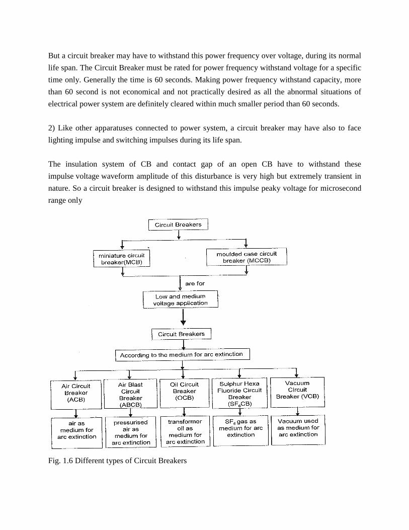
Fig. 1.6 Different types of Circuit Breakers
Air Circuit Breaker and Air Blast Circuit Breaker
This type of circuit breakers, is those kind of circuit breaker which operates in air at atmospheric
pressure. After development of oil circuit breaker, the medium voltage air circuit
breaker (ACB) is replaced completely by oil circuit breaker in different countries. But in
countries like France and Italy, ACBs are still preferable choice up to voltage 15 KV. It is also
good choice to avoid the risk of oil fire, in case of oil circuit breaker. In America ACBs were
exclusively used for the system up to 15 KV until the development of new vacuum and
SF6 circuit breakers.
Working Principle of Air Circuit Breaker
The working principle of this breaker is rather different from those in any other types of circuit
breakers. The main aim of all kind of circuit breaker is to prevent the reestablishment of arcing
after current zero by creating a situation where in the contact gap will withstand the system
recovery voltage. The air circuit breaker does the same but in different manner. For
interrupting arc it creates an arc voltage in excess of the supply voltage. Arc voltage is defined as
the minimum voltage required maintaining the arc. This circuit breaker increases the
arc voltage by mainly three different ways,
1. It may increase the arc voltage by cooling the arc plasma. As the temperature of arc plasma
is decreased, the mobility of the particle in arc plasma is reduced, hence
more voltage gradient is required to maintain the arc.
2. It may increase the arc voltage by lengthening the arc path. As the length of arc path is
increased, the resistance of the path is increased, and hence to maintain the same
arc current more voltage is required to be applied across the arc path. That means
arc voltage is increased.
3. Splitting up the arc into a number of series arcs also increases the arc voltage.
Types of ACB
There are mainly two types of ACB are available.
1. Plain air circuit breaker.
2. Air blast Circuit Breaker.
Operation of ACB
The first objective is usually achieved by forcing the arc into contact with as large an
area as possible of insulating material. Every air circuit breaker is fitted with a chamber
surrounding the contact. This chamber is called „arc chute‟. The arc is driven into it. If
inside of the arc chute is suitably shaped, and if the arc can be made conform to the
shape, the arc chute wall will help to achieve cooling. This type of arc chute should be
made from some kind of refractory material. High temperature plastics reinforced with
glass fiber and ceramics are preferable materials for making arc chute.
The second objective that is lengthening the arc path, is achieved concurrently with fist
objective. If the inner walls of the arc chute is shaped in such a way that the arc is not
only forced into close proximity with it but also driven into a serpentine channel
projected on the arc chute wall. The lengthening of the arc path increases the
arc resistance.
The third technique is achieved by using metal arc slitter inside the arc chute. The main
arc chute is divided into numbers of small compartments by using metallic separation
plates. These metallic separation plates are actually the arc splitters and each of the
small compartments behaves as individual mini arc chute. In this system the initial arc is
split into a number of series arcs, each of which will have its won mini arc chute. So
each of the split arcs has its won cooling and lengthening effect due to its won mini arc
chute and hence individual split arc voltage becomes high. These collectively, make the
over all arc voltage, much higher than the system voltage.
This was working principle of air circuit breaker now we will discuss in details the
operation of ACB in practice.
The air circuit breaker, operated within the voltage level 1 KV, does not require any arc
control device. Mainly for heavy fault current on low voltages (low voltage level above 1 KV)
ABCs with appropriate arc control device, are good choice. These breakers normally have two
pairs of contacts. The main pair of contacts carries the current at normal load and these contacts
are made of copper. The additional pair is the arcing contact and is made of carbon. When circuit
breaker is being opened, the main contacts open first and during opening of main contacts the
arcing contacts are still in touch with each other. As the current gets, a parallel low resistive path
through the arcing contact during opening of main contacts, there will not be any arcing in the
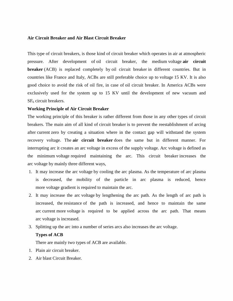
main contact. The arcing is only initiated when finally the arcing contacts are separated. The
each of the arc contacts is fitted with an arc runner which helps, the arc discharge to move
upward due to both thermal and electromagnetic effects as shown in the figure.
Fig. 1.7 Air Circuit Breaker
As the arc is driven upward it enters in the arc chute, consisting of splitters. The arc in
chute will become colder, lengthen and split hence arc voltage becomes much larger than
system voltage at the time of operation of air circuit breaker, and therefore the arc is quenched
finally during the current zero.
Although this type of circuit breakers have become obsolete for medium voltage application, but
they are still preferable choice for high current rating in low voltage application.
Air Blast Circuit Breaker
These types of air circuit breaker were used for the system voltage of 245 KV, 420 KV and
even more, especially where faster breaker operation was required. Air blast circuit breaker has
some specific advantages over oil circuit breaker which are listed as follows,
1. There is no chance of fire hazard caused by oil.
2. The breaking speed of circuit breaker is much higher during operation of air blast circuit
breaker.
3. Arc quenching is much faster during operation of air blast circuit breaker.
4. The duration of arc is same for all values of small as well as high currents interruptions.

5. As the duration of arc is smaller, so lesser amount of heat realized from arc to
current carrying contacts hence the service life of the contacts becomes longer.
6. The stability of the system can be well maintained as it depends on the speed of operation of
circuit breaker.
7. Requires much less maintenance compared to oil circuit breaker.
There are also some disadvantages of air blast circuit breakers-
1. In order to have frequent operations, it is necessary to have sufficiently high capacity air
compressor.
2. Frequent maintenance of compressor, associated air pipes and automatic control equipments
is also required.
3. Due to high speed current interruption there is always a chance of high rate of rise of re-
striking voltage and current chopping.
4. There also a chance of air pressure leakage from air pipes junctions.
As we said earlier that there are mainly two types of ACB, plain air circuit breaker and air blast
circuit breaker. But the later can be sub divided further into three different categories.
1. Axial Blast ACB.
2. Axial Blast ACB with side moving contact.
3. Cross Blast ACB.
Axial Blast Air Circuit Breaker
Fig. 1.8 Axial Blast ACB
In axial blast ACB the moving contact is in contact with fixed contact with the help of a spring
pressure as shown in the figure. There is a nozzle orifice in the fixed contact which is blocked by
tip of the moving contact at normal closed condition of the breaker. When fault occurs, the high
pressure air is introduced into the arcing chamber. The air pressure will counter the spring
pressure and deforms the spring hence the moving contact is withdrawn from the fixed contact
and nozzle hole becomes open. At the same time the high pressure air starts flowing along the
arc through the fixed contact nozzle orifice. This axial flow of air along the arc through the
nozzle orifice will make the arc lengthen and colder hence arc voltage become much higher than
system voltage that means system voltage is insufficient to sustain the arc consequently the arc is
quenched.
circuit breaker with side moving contact” title=”Axial Blast Air Circuit Breaker with side
moving contact” class=”alignleft”/>
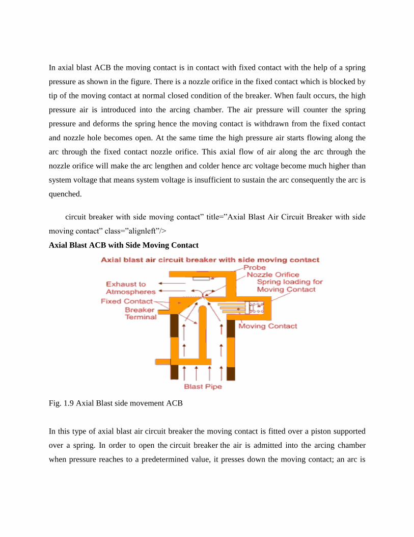
Axial Blast ACB with Side Moving Contact
Fig. 1.9 Axial Blast side movement ACB
In this type of axial blast air circuit breaker the moving contact is fitted over a piston supported
over a spring. In order to open the circuit breaker the air is admitted into the arcing chamber
when pressure reaches to a predetermined value, it presses down the moving contact; an arc is
drawn between the fixed and moving contacts. The air blast immediately transfers the arc to the
arcing electrode and is consequently quenched by the axial flow of air.
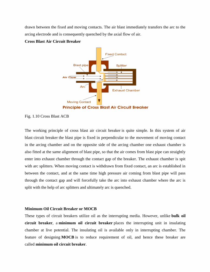
Cross Blast Air Circuit Breaker
Fig. 1.10 Cross Blast ACB
The working principle of cross blast air circuit breaker is quite simple. In this system of air
blast circuit breaker the blast pipe is fixed in perpendicular to the movement of moving contact
in the arcing chamber and on the opposite side of the arcing chamber one exhaust chamber is
also fitted at the same alignment of blast pipe, so that the air comes from blast pipe can straightly
enter into exhaust chamber through the contact gap of the breaker. The exhaust chamber is spit
with arc splitters. When moving contact is withdrawn from fixed contact, an arc is established in
between the contact, and at the same time high pressure air coming from blast pipe will pass
through the contact gap and will forcefully take the arc into exhaust chamber where the arc is
split with the help of arc splitters and ultimately arc is quenched.
Minimum Oil Circuit Breaker or MOCB
These types of circuit breakers utilize oil as the interrupting media. However, unlike bulk oil
circuit breaker, a minimum oil circuit breaker places the interrupting unit in insulating
chamber at live potential. The insulating oil is available only in interrupting chamber. The
feature of designing MOCB is to reduce requirement of oil, and hence these breaker are
called minimum oil circuit breaker.
As the volume of the oil in bulk oil circuit breaker is huge, the chances of fire hazard in bulk oil
system are more. For avoiding unwanted fire hazard in the system, one important development in
the design of oil circuit breaker has been introduced where use of oil in the circuit breaker is
much less than that of bulk oil circuit breaker. It has been decided that the oil in the circuit
breaker should be used only as arc quenching media not as an insulating media. Then the concept
of minimum oil circuit breaker comes. In this type of circuit breaker the arc interrupting device
is enclosed in a tank of insulating material which as a whole is at live potential of system. This
chamber is called arcing chamber or interrupting pot. The gas pressure developed in the arcing
chamber depends upon the current to be interrupted. Higher the current to be interrupted causes
larger the gas pressure developed inside the chamber, hence better the arc quenching. But this
put a limit on the design of the arc chamber for mechanical stresses. With use of better insulating
materials for the arcing chambers such as glass fiber, reinforced synthetic resin etc,
the minimum oil circuit breaker are able to meet easily the increased fault levels of the
system.
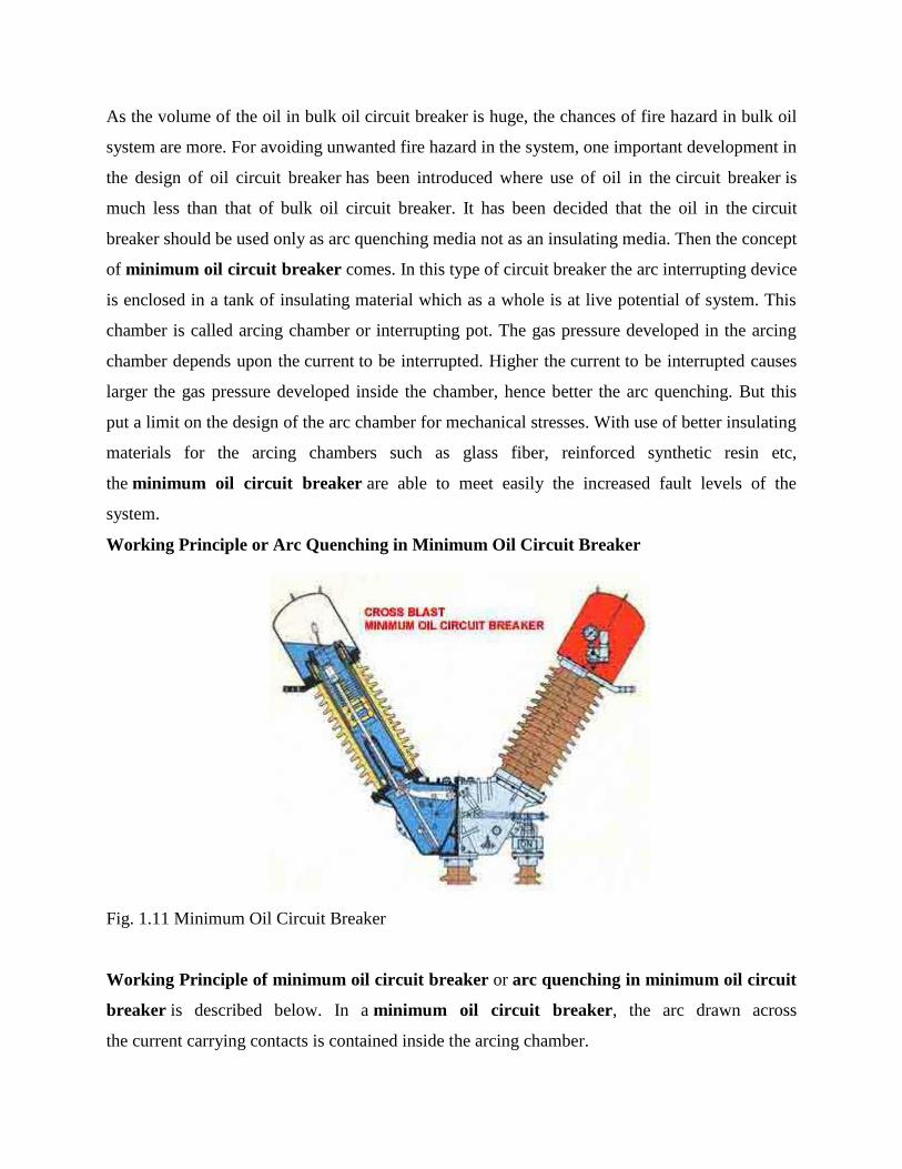
Working Principle or Arc Quenching in Minimum Oil Circuit Breaker
Fig. 1.11 Minimum Oil Circuit Breaker
Working Principle of minimum oil circuit breaker or arc quenching in minimum oil circuit
breaker is described below. In a minimum oil circuit breaker, the arc drawn across
the current carrying contacts is contained inside the arcing chamber.

Hence the hydrogen bubble formed by the vaporized oil is trapped inside the chamber. As the
contacts continue to move, after its certain travel an exit vent becomes available for exhausting
the trapped hydrogen gas. There are two different types of arcing chamber is available in terms
of venting are provided in the arcing chambers. One is axial venting and other is radial venting.
In axial venting, gases (mostly Hydrogen), produced due to vaporization of oil and
decomposition of oil during arc, will sweep the arc in axial or longitudinal direction.
Let‟s have a look on working principle Minimum Oil Circuit Breaker with axial venting arc
chamber. The moving contact has just been separated and arc is initiated in MOCB.
The ionized gas around the arc sweep away through upper vent and cold oil enters into the arcing
chamber through the lower vent in axial direction as soon as the moving contact tip crosses the
lower vent opening and final arc quenching in minimum oil circuit breaker occurs the cold oil
occupies the gap between fixed contact and moving contact and the minimum oil circuit
breaker finally comes into open position. Whereas in case of radial venting or cross blast, the
gases (mostly Hydrogen) sweep the arc in radial or transverse direction. The axial venting
generates high gas pressure and hence has high dielectric strength, so it is mainly used for
interrupting low current at high voltage. On the other hand radial venting produces relatively
low gas pressure and hence low dielectric strength so it can be used for low voltage and
high current interruption. Many times the combination of both is used in minimum oil circuit
breaker so that the chamber is equally efficient to interrupt low current as well as high current.
These types of circuit breaker are available up to 8000 MVA at 245 KV.
Vacuum Circuit Breaker or VCB
A vacuum circuit breaker is such kind of circuit breaker where the arc quenching takes place in
vacuum. The technology is suitable for mainly medium voltage application. For
higher voltage vacuum technology has been developed but not commercially viable. The
operation of opening and closing of current carrying contacts and associated arc interruption take
place in a vacuum chamber in the breaker which is called vacuum interrupter. The vacuum
interrupter consists of a steel arc chamber in the centre symmetrically arranged ceramic
insulators. The vacuum pressure inside a vacuum interrupter is normally maintained at 10 – 6
bar.
The material used for current carrying contacts plays an important role in the performance of
the vacuum circuit breaker. CuCr is the most ideal material to make VCB contacts. Vacuum
interrupter technology was first introduced in the year of 1960. But still it is a developing
technology. As time goes on, the size of the vacuum interrupter is being reducing from its early
1960‟s size due to different technical developments in this field of engineering. The contact
geometry is also improving with time, from butt contact of early days it gradually changes to
spiral shape, cup shape and axial magnetic field contact. Thevacuum circuit breaker is today
recognized as most reliable current interruption technology for medium voltage switchgear. It
requires minimum maintenance compared to other circuit breaker technologies.
Advantages of Vacuum Circuit Breaker or VCB
Service life of vacuum circuit breaker is much longer than other types of circuit breakers. There
is no chance of fire hazard as oil circuit breaker. It is much environment friendly than SF6 Circuit
breaker. Beside of that contraction of VCB is much user friendly. Replacement of vacuum
interrupter (VI) is much convenient.
Operation of Vacuum Circuit Breaker
The main aim of any circuit breaker is to quench arc during current zero crossing, by establishing
high dielectric strength in between the contacts so that reestablishment of arc after current zero
becomes impossible. The dielectric strength of vacuum is eight times greater than that of air and
four times greater than that of SF6 gas. This high dielectric strength makes it possible to quench
a vacuum arc within very small contact gap. For short contact gap, low contact mass and no
compression of medium the drive energy required in vacuum circuit breaker is minimum. When
two face to face contact areas are just being separated to each other, they do not be separated
instantly, contact area on the contact face is being reduced and ultimately comes to a point and
then they are finally de-touched. Although this happens in a fraction of micro second but it is the
fact. At this instant of de-touching of contacts in a vacuum, the current through the contacts
concentrated on that last contact point on the contact surface and makes a hot spot. As it is
vacuum, the metal on the contact surface is easily vaporized due to that hot spot and create a
conducting media for arc path. Then the arc will be initiated and continued until the
next current zero.
At current zero this vacuum arc is extinguished and the conducting metal vapor is re-condensed
on the contact surface. At this point, the contacts are already separated hence there is no question
of re-vaporization of contact surface, for next cycle of current. That means, the arc cannot be
reestablished again. In this way vacuum circuit breaker prevents the reestablishment of arc by
producing high dielectric strength in the contact gap after current zero. There are two types of arc
shapes. For interrupting current up to 10 kA, the arc remains diffused and the form of vapor
discharge and cover the entire contact surface. Above 10 kA the diffused arc is constricted
considerably by its own magnetic field and it contracts. The phenomenon gives rise over heating
of contact at its center. In order to prevent this, the design of the contacts should be such that the
arc does not remain stationary but keeps travelling by its own magnetic field. Specially designed
contact shape of vacuum circuit breaker make the constricted stationary arc travel along the
surface of the contacts, thereby causing minimum and uniform contact erosion.
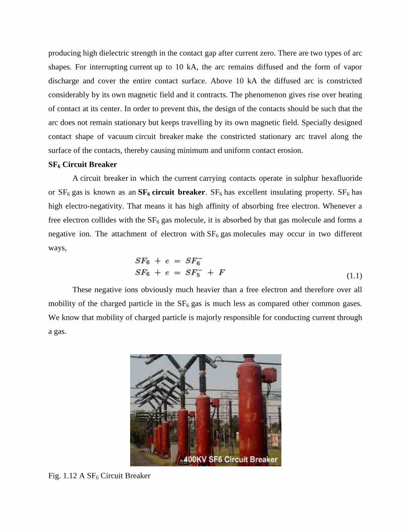
SF6 Circuit Breaker
A circuit breaker in which the current carrying contacts operate in sulphur hexafluoride
or SF6 gas is known as an SF6 circuit breaker. SF6 has excellent insulating property. SF6 has
high electro-negativity. That means it has high affinity of absorbing free electron. Whenever a
free electron collides with the SF6 gas molecule, it is absorbed by that gas molecule and forms a
negative ion. The attachment of electron with SF6 gas molecules may occur in two different
ways,
(1.1)
These negative ions obviously much heavier than a free electron and therefore over all
mobility of the charged particle in the SF6 gas is much less as compared other common gases.
We know that mobility of charged particle is majorly responsible for conducting current through
a gas.
Fig. 1.12 A SF6 Circuit Breaker

Hence, for heavier and less mobile charged particles in SF6 gas, it acquires very high
dielectric strength. Not only the gas has a good dielectric strength but also it has the unique
property of fast recombination after the source energizing the spark is removed. The gas has also
very good heat transfer property. Due to its low gaseous viscosity (because of less molecular
mobility) SF6 gas can efficiently transfer heat by convection. So due to its high dielectric
strength and high cooling effect SF6gas is approximately 100 times more effective arc quenching
media than air. Due to these unique properties of this gas SF6 circuit breaker is used in
complete range of mediumvoltage and high voltage electrical power system. These circuit
breakers are available for the voltage ranges from 33KV to 800KV and even more.
Disadvantages of SF6 CB
The SF6 gas is identified as a greenhouse gas, safety regulation are being introduced in
many countries in order to prevent its release into atmosphere. Puffer type design of SF6 CB
needs a high mechanical energy which is almost five times greater than that of oil circuit breaker.
Types of SF6 Circuit Breaker
There are mainly three types of SF6 CB depending upon the voltage level of application-
1. Single interrupter SF6 CB applied for up to 245 KV(220 KV) system.
2. Two interrupter SF6 CB applied for up to 420 KV(400 KV) system.
3. Four interrupter SF6 CB applied for up to 800 KV(715 KV) system.
Working of SF6 Circuit Breaker
The working of SF6 CB of first generation was quite simple it is some extent similar to
air blast circuit breaker. Here SF6 gas was compressed and stored in a high pressure reservoir.
During operation of SF6 circuit breaker this highly compressed gas is released through the arc
in breaker and collected to relatively low pressure reservoir and then it pumped back to the high
pressure reservoir for re utilize.
The working of SF6 circuit breaker is little bit different in modern time. Innovation of
puffer type design makes operation of SF6 CB much easier. In buffer type design, the arc energy
is utilized to develop pressure in the arcing chamber for arc quenching. Here the breaker is filled
with SF6 gas at rated pressure. There are two fixed contact fitted with a specific contact gap. A
sliding cylinder bridges these to fixed contacts. The cylinder can axially slide upward and
downward along the contacts. There is one stationary piston inside the cylinder which is fixed
with other stationary parts of the SF6 circuit breaker, in such a way that it cannot change its
position during the movement of the cylinder. As the piston is fixed and cylinder is movable or
sliding, the internal volume of the cylinder changes when the cylinder slides.
During opening of the breaker the cylinder moves downwards against position of the
fixed piston hence the volume inside the cylinder is reduced which produces compressed SF6gas
inside the cylinder. The cylinder has numbers of side vents which were blocked by upper fixed
contact body during closed position. As the cylinder move further downwards, these vent
openings cross the upper fixed contact, and become unblocked and then compressed SF6 gas
inside the cylinder will come out through this vents in high speed towards the arc and passes
through the axial hole of the both fixed contacts. The arc is quenched during this flow of SF6 gas.
During closing of the circuit breaker, the sliding cylinder moves upwards and as the
position of piston remains at fixed height, the volume of the cylinder increases which introduces
low pressure inside the cylinder compared to the surrounding. Due to this pressure difference
SF6 gas from surrounding will try to enter in the cylinder. The higher pressure gas will come
through the axial hole of both fixed contact and enters into cylinder via vent and during this
flow; the gas will quench the arc.
D.C circuit breakers
Miniature circuit breakers available for use in direct current
Nowadays we use more commonly miniature circuit breaker or MCB in low voltage electrical
network instead of fuse. The MCB has some advantages compared to fuse.
1. It automatically switches off the electrical circuit during abnormal condition of the network
means in over load condition as well as faulty condition. The fuse does not sense but miniature
circuit breaker does it in more reliable way. MCB is much more sensitive to over current than
fuse.
2. Another advantage is, as the switch operating knob comes at its off position during tripping,
the faulty zone of the electrical circuit can easily be identified. But in case of fuse, fuse wire
should be checked by opening fuse grip or cutout from fuse base, for confirming the blow of fuse
wire.
3. Quick restoration of supply cannot be possible in case of fuse as because fuses have to be

replaced for restoring the supply. But in the case of MCB, quick restoration is possible by just
switching on operation.
4. Handling MCB is more electrically safe than fuse.
Because of too many advantages of MCB over fuse units, in modern low voltage electrical
network, miniature circuit breaker is mostly used instead of backdated fuse unit. Only one
disadvantage of MCB over fuse is that this system is more costly than fuse unit system.
Working Principle Miniature Circuit Breaker
There are two arrangement of operation of miniature circuit breaker. One due to
thermal effect of over current and other due to electromagnetic effect of over current. The
thermal operation of miniature circuit breaker is achieved with a bimetallic strip whenever
continuous over current flows through MCB, the bimetallic strip is heated and deflects by
bending. This deflection of bimetallic strip releases mechanical latch. As this mechanical latch is
attached with operating mechanism, it causes to open the miniaturecircuit breaker contacts. But
during short circuit condition, sudden rising of current, causes electromechanical displacement of
plunger associated with tripping coil or solenoid of MCB. The plunger strikes the trip lever
causing immediate release of latch mechanism consequently open the circuit breaker contacts.
This was a simple explanation of miniature circuit breaker working principle.
Miniature Circuit Breaker Construction
Miniature circuit breaker construction is very simple, robust and maintenance free. Generally
a MCB is not repaired or maintained, it just replaced by new one when required. A
miniature circuit breaker has normally three main constructional parts. These are:
Frame of Miniature Circuit Breaker
The frame of miniature circuit breaker is a molded case. This is a rigid, strong, insulated
housing in which the other components are mounted.
Operating Mechanism of Miniature Circuit Breaker
The operating mechanism of miniature circuit breaker provides the means of manual
opening and closing operation of miniature circuit breaker. It has three-positions “ON,” “OFF,”
and “TRIPPED”. The external switching latch can be in the “TRIPPED” position, if the MCB is
tripped due to over-current. When manually switch off the MCB, the switching latch will be in

“OFF” position. In close condition of MCB, the switch is positioned at “ON”. By observing the
positions of the switching latch one can determine the condition of MCB whether it is closed,
tripped or manually switched off.
Trip Unit of Miniature Circuit Breaker
The trip unit is the main part, responsible for proper working of miniature circuit
breaker. Two main types of trip mechanism are provided in MCB. A bimetal provides
protection against over load current and an electromagnet provides protection against short-
circuit current.
Operation of Miniature Circuit Breaker
There are three mechanisms provided in a single miniature circuit breaker to make it
switched off. If we carefully observe the picture beside, we will find there are mainly one bi –
metallic strip, one trip coil and one hand operated on – off lever. Electric current carrying path of
a miniature circuit breaker shown in the picture is like follows. First left hand side power
terminal – then bimetallic strip – then current coil or trip coil – then moving contact – then fixed
contact and – lastly right had side power terminal. All are arranged in series.
If circuit is overloaded for long time, the bi – metallic strip becomes over heated and
deformed. This deformation of bi metallic strip causes, displacement of latch point. The moving
contact of the MCB is so arranged by means of spring pressure, with this latch point, that a little
displacement of latch causes, release of spring and makes the moving contact to move for
opening the MCB. The current coil or trip coil is placed such a manner, that during short circuit
fault the mmf of that coil causes its plunger to hit the same latch point and make the latch to be
displaced. Hence the MCB will open in same manner. Again when operating lever of the
miniature circuit breaker is operated by hand, that means when we make the MCB at off position
manually, the same latch point is displaced as a result moving contact separated from fixed
contact in same manner. So, whatever may be the operating mechanism, that means, may be due
to deformation of bi – metallic strip, due to increased mmf of trip coil or may due to manual
operation, actually the same latch point is displaced and same deformed spring is released, which
ultimately responsible for movement of the moving contact. When the the moving contact
separated from fixed contact, there may be a high chance of arc.

MODULE- II
Relay Classification
Protection relays can be classified in accordance with their construction, the incoming signal and
function
Construction
• Electromechanical
• Solid State
• Microprocessor
• Numerical
Incoming Signal
• Current
• Voltage
• Power
• Frequency
• Temperature
• Pressure
• Speed
• Others
Function
• Overcurrent
• Directional Overcurrent
• Distance
• Over voltage
• Differential
• Reverse Power
• Others
Electromechanical Relays
These relays are constructed with electrical, magnetic & mechanical components & have an
operating coil & various contacts, & are very robust & reliable. Based on the construction,
characteristics, these are classified in three groups.
Attraction Relays
Attraction relays can be AC & DC and operate by the movement of a piece of iron when it is
attracted by the magnetic field produced by a coil. There are two main types of relays:
1. The attracted armature type
2. Solenoid type relay
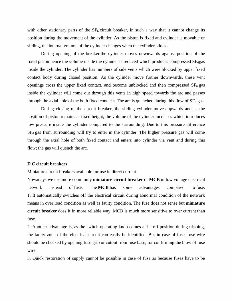
Attracted Armature Relays
• Consists of a bar or plate (made of iron) that pivots when it is attracted towards the coil.
• The armature carries the moving part of the contact, which is closed or opened, according
to the design, when the armature is attracted to the coil.
Fig. 2.1 Hinged Armature Relay
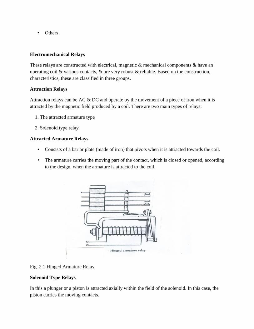
Solenoid Type Relays
In this a plunger or a piston is attracted axially within the field of the solenoid. In this case, the
piston carries the moving contacts.
Fig. 2.2 Solenoid-type Relay
The force of attraction =
Where, K1 depends on
• The number of turns of the coil
• The air gap
• The effective area
• The reluctance of the magnetic circuit
K2 is the restraining force, usually produced by spring
For threshold or balanced condition, the resultant force is zero.
𝐼 = 𝐾1
𝐾2 (2.1)
In order to control the value of current at which relay operates, the parameters K1 and K2 may
adjusted. Attraction relays effectively have no time-delay and are widely used when
instantaneous operation is required
Relays with Movable Coils
This type of relay consists of a rotating movement with a small coil suspended or pivoted with
the freedom to rotate between the poles of a permanent magnet.
2
1 2KI K
2
1 2KI K

The coil is restrained by two special springs which also serve as connections to carry
the current to the coil
Fig. 2.3 Moving-coil relay
The torque produced in the coil is
(2.2)
where,
T= Torque, B= flux density, l= length of the coil, a= distance between the two sides of the coil
i=current flowing through the coil , N=number of turns in the coil
• The relay has inverse type characteristic
Induction Relays
• An induction relay works only with AC
• It consists of an electromagnetic system Which operates on a moving conductor,
generally in the form of a DISC or CUP
Production of Actuating Torque
Various quantities are shown at instant when
• Both fluxes are directed downward
T BlaNi
• Are increasing in magnitude
Let
It may be assumed with negligible error that the paths in which rotor current flow have negligible
self inductance.
(2.2)
Since sinusoidal flux waves are assumed, we may substitute the rms values of the fluxes for the
crest values in the above equation.
• It may be noted that the net force is same at every instant.
• The net force is directed from the point where the leading flux process the rotor towards the
point where the lagging flux pierces the rotor.
• Actuating force is produced in the presence of out of phase fluxes.
• Maximum force is produced when θ=90o
Classification Of Induction Relays
1. Shaded pole relay
2. Watt-hour- meter type relay
3. Cup type relay
• The air gap flux produced by the current flowing in a single coil is split into two out of phase
components by a so called „Shading Ring‟ generally of copper, that encircles part of the pole
face of each pole at the air gap.
1 1() sin( )mt t
2 1F F F

Fig.2.3 Shaded-pole induction relay
• The shading ring may be replaced by coils if control of operation of the shaded pole relay is
desired.
• The inertia of the disc provides the time delay characteristics.
Watt Hour –Meter Structure
Fig.2.4 Watt-hour meter relay
• This structure gets its name from the fact that it is used in watt hour meters.
• It contains two separate coils on two different magnetic circuit, each of which produces one of two
necessary fluxes for driving the rotor, which is also a disc
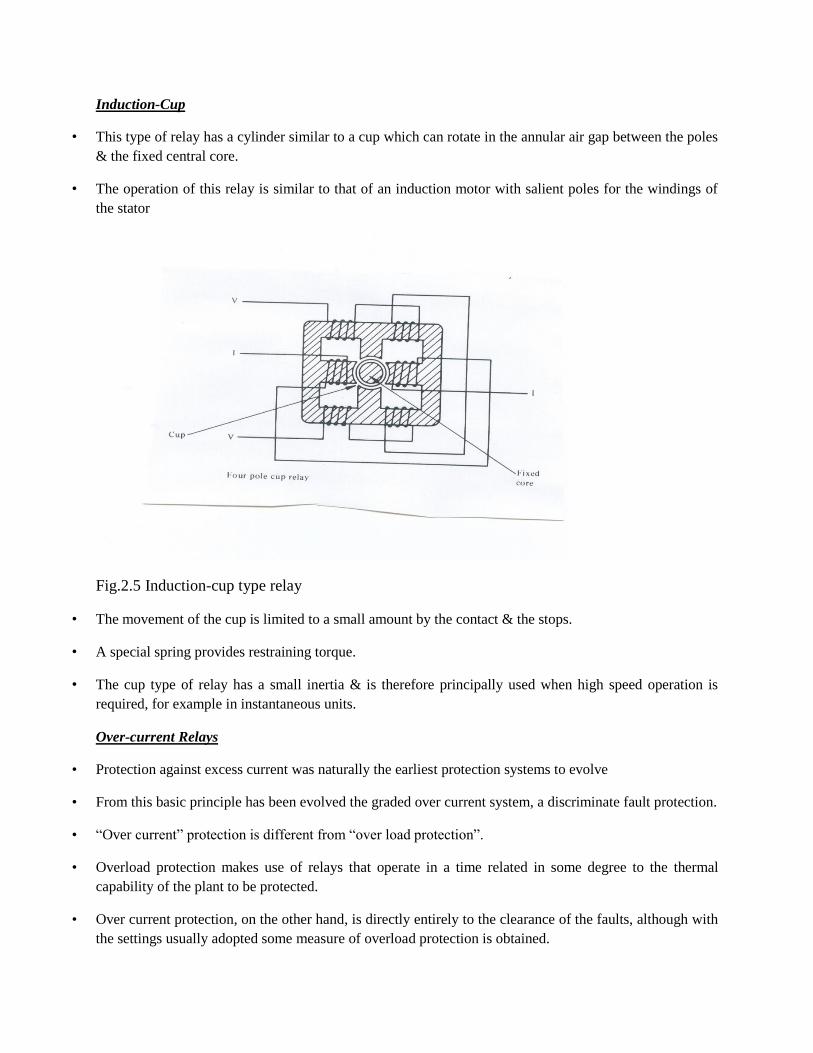
Induction-Cup
• This type of relay has a cylinder similar to a cup which can rotate in the annular air gap between the poles
& the fixed central core.
• The operation of this relay is similar to that of an induction motor with salient poles for the windings of
the stator
Fig.2.5 Induction-cup type relay
• The movement of the cup is limited to a small amount by the contact & the stops.
• A special spring provides restraining torque.
• The cup type of relay has a small inertia & is therefore principally used when high speed operation is
required, for example in instantaneous units.
Over-current Relays
• Protection against excess current was naturally the earliest protection systems to evolve
• From this basic principle has been evolved the graded over current system, a discriminate fault protection.
• “Over current” protection is different from “over load protection”.
• Overload protection makes use of relays that operate in a time related in some degree to the thermal
capability of the plant to be protected.
• Over current protection, on the other hand, is directly entirely to the clearance of the faults, although with
the settings usually adopted some measure of overload protection is obtained.
Types of over current Relays
• Based on the relay operating characteristics , over current relays can be classified into three groups
– Definite current or instantaneous
– Definite time
– Inverse time
Definite-Current Relays
• This type of relay operates instantaneously when the current reaches a predetermined value.
Definite Time Current Relays
• This type of relay operates after a definite time when the current reaches a pre-determined value.
Inverse Time Relays
• The fundamental property of these relays is that they operate in a time that is inversely
proportional to the fault current. Inverse time relays are generally classified in accordance with
their characteristic curve that indicates the speed of operation.
• Inverse-time relays are also referred as inverse definite minimum time or IDMT over-current
relays
Setting the Parameters of Time Delay Over-current Relay
Pick-up setting
• The pick-up setting, or plug setting, is used to define the pick-up current of the relay, and fault
currents seen by the relay are expressed as multiples of plug setting.
• Plug setting multiplier (PSM) is defined as the ratio of the fault current in secondary Amps to the
relay plug setting.
• For phase relays the pick-up setting is determined by allowing a margin for overload above the
nominal current, as in the following expression
Pick-up setting = (OLF x Inom) / CTR
where,
OLF = Overload factor that depends on the element being protected.
Inom = Nominal circuit current rating

CTR = CT Ratio
Time dial setting
• The time-dial setting adjusts the time –delay before the relay operates whenever the fault
current reaches a value equal to, or greater than the relay setting.
• The time-dial setting is also referred to as time multiplier setting (TMS)
Discrimination by Time
In this method an appropriate time interval is given by each of the relays controlling the CBs
in a power system to ensure that the breaker nearest the fault opens first.
A simple radial distribution system is considered to illustrate this principle
Fig. 2.6 A radial distribution system with time-discrimination
• The main disadvantage of this method of discrimination is that the longest fault clearance
time occurs for faults in the section closest to the power source, where the fault level is
highest.
Discrimination by Current
• Discrimination by current relies on the fact that the fault current varies with the position
of the fault , because of the difference in impedance values between the source and the
fault .
• The relays controlling CBs are set to operate at suitably tapered values such that only the
relay nearest the fault trips its circuit breaker.
Inverse time over current relay characteristic is evolved to overcome the limitations imposed by
the independent use of either time or over current coordination.
Directional over-current Relays
1. When fault current can flow in both directions through the relay location, it is necessary
to make the response of the relay directional by introduction of directional control
elements.
2. These are basically power measuring devices in which the system voltage is used as a
reference for establishing the relative phase of the fault current.
Basically, an AC directional relay can recognize certain difference in phase angle between
two quantities, just as a D.C. directional relay recognize difference in polarity
The Polarizing Quantity of a Directional Relay
1. It is the reference against which the phase angle of the other quantity is compared.
Consequently the phase angle of the polarizing quantity must remain fixed when other
quantity suffers wide change in phase angle.
2. The voltage is chosen as the “polarizing” quantity in the current-voltage induction type
directional relay.
3. Four pole induction cup constructions is normally used.
Distance relay
Distance relay is used for the protection of transmission line
In a distance relay, instead of comparing the local line current with the current at far end
of line, the relay compares the local current with the local voltage in the corresponding
phase or suitable components of them
Principle of Operation of Distance Relay
1. The basic principle of measurement involves the comparison of fault current seen by the
relay with the voltage at relaying point; by comparing these two quantities.
2. It is possible to determine whether the impedance of the line up to the point of fault is
greater than or less than the predetermined reach point impedance
There are two types of torques
1. Restraining torque
2Fr VT
2. Operating torque
2F0 IT
The relay trips when T0 greater than Tr
The constant K depends on the design of the electromagnets.
Types of Distance Relay
Distance relays are classified depending on their operating characteristic in the R-X
plane
• Impedance Relay
• Mho Relay
• Reactance Relay
Disadvantage of Impedance Relay
1. It is not directional.
2. It is affected by the Arc resistance
3. It is highly sensitive to oscillations on the power system, due to large area covered by its
circular characteristic
Operating Characteristic of Mho Relay
The Mho relay combines the properties of impedance and directional relays. Its characteristic is
inherently directional and the relay only operates for faults in front of the relay location.
Operating Characteristic of Reactance Relay
1. The reactance relay is designed to measure only reactive component of the line reactance.
2. The fault resistance has no affect on the reactance relay
Differential Relay
• The most positive method of protecting a circuit is to arrange relays to compare the
currents entering and leaving it, which should be the same under normal conditions and
during an external fault. Any difference current must be flowing in to a fault within the
protected circuit
Differential Protection current balance
2 2
F FKI V

• When this system is applied to electrical equipment (Generator stator windings,
Transformer, Bus bars etc.) it is called differential current protection.
• When it is applied to lines and cables it is called pilot differential protection because pilot
wires or an equivalent link or channel is required to bring the current to the relay from the
remote end of the line.
The CTs at both ends of the protected circuit connected so that for through load or through fault
conditions current circulates between the interconnected CTs. The over-current relay is normally
connected across equipotential points and therefore doesn‟t operate.
• Circulating current balance methods are widely used for apparatus protection where CTs
are within the same substation area and interconnecting leads between CTs are short (e.g.
generator stator windings, Transformer, Bus bars etc.)
• The circulating current balance method is also called longitudinal differential protection
or Merz-Price differential protection system.
• The current in the differential relay would be proportional to the phasor difference
between the currents that enter and leave the protected circuit. If the current through the
relay exceeds the pick-up value, then the relay will operate.
Static Relays
Advantages of Static Relays
• Due to the amplification of energizing signals obtainable, the sources need only provide
low power. Therefore the size of the associated current and voltage transformers could be
reduced.
• Improved accuracy and selectivity.
• Fast operation of relays and hence fast clearance of faults.
• Flexibility of circuitry would allow new and improved characteristics.
• The relays would be unaffected by the number of operations.
Basic Circuits Employed
• Timers
• Phase comparators
• Level detectors
• Integrators

• Polarity detectors
High reliability operational amplifiers are used for realizing the basic components of static relays
Numerical Protection
Numerical relays are technically superior to the conventional type relays. Their general
characteristics are:
• Reliability
• Self diagnosis
• Event and disturbance records
• Adaptive Protection
• Integration of Digital Systems
Typical Architecture of Numerical Relays
Numerical relays are made up from modules with well defined functions.
Fig. 2.7 Numerical Relay Architecture
Digial Relay Logic
• The digital relay does not record the analog signal,but only samples of the signal, which
are spread in time.

• the mathematics of discrete signal processing is used.
• The relay is programmed to apply various forms of digital signal processing algorithms to
the observed samples and based on the results of these computations,the decision to trip
is made.
Protection of Feeders
Media used for Protection Signaling
• Power - line - carrier circuits
• Pilot Wires
Power Line Carrier
• The signal propagation medium is power line itself, communication between ends of the
power line being effected by means of a superimposed carrier, carrier frequency signal
carried by the power circuit conductors.
• The band of frequencies employed for the carrier frequency signal is 70-700khz.
• 2. Power level is 1-2 w for continuous signaling.
• 3. 10-20 w for short -time signaling
Fig. 2.8 Over-current Protection and Earth Faults
Generator Protection
• The range of size of generators extends from a few hundred KVA to more than 500MVA

• Small and Medium sized sets may be directly connected to the distribution system
A larger unit is usually associated with an individual transformer, through which the set is
coupled to the EHV transmission system. No switchgear is provided between the generator and
transformer, which are treated as a unit. The neutral point of the generator is usually earthed, so
as to facilitate the protection of the stator winding and associated system
• Impedance is inserted in the earthing lead to limit the magnitude of the earth fault current.
• Severe arcing to the machine core burns the iron at the point of fault and welds the
laminations together. The welding of laminations would most likely result in local
overheating.
• In case of severe damage to the core, it may require rebuilding of the core, which would
involve expensive rebuilding of the windings
• Practice as to the degree of fault current limitation varies from approximately rated
current on one hand to comparatively low values on the other
• Sometimes, it is asserted that if fault current is limited to 5A, burning of the core will not
occur readily.
• Generators which are directly connected to the transmission or distribution system are
usually earthed through a resistance which will pass approximately rated current to a
terminal earth fault
• In case of generator-transformer unit, the generator winding and primary winding of a
transformer can be treated as an isolated system which is not influenced by the earthing
requirements of the transmission system
• Modern practice is to use a large earthing transformer (5-100 KVA) – the secondary
winding which is designed for 100-500V is loaded with a resistor of a value, which when
referred through the transformer ratio, will pass a suitable fault current the resistor is
therefore of low value and can be of rugged construction
• The equivalent resistance in the stator circuit should not exceed the impedance as system
frequency of the total summated capacitance of the three phases
• The resistance component of the fault current should not be less than the residual
capacitance current, that is 3 Ico

Transformer Protection
• The power transformer is one of the most important links in a power transmission and
distribution system.
• It is a highly reliable piece of equipment. This reliability depends on
• adequate design
• careful erection
• proper maintenance
• Application of protection system.
Protection Equipment Includes
1. Surge diverters
2. Gas relay: It gives early warning of a slowly developing fault, permitting shutdown and repair
before severe damage can occur.
3. Electrical relays.
• The choice of suitable protection is also governed by economic considerations. Although
this factor is not unique to power transformers, it is brought in prominence by the wide
range of transformer ratings used( few KVA to several hundred MVA)
• Only the simplest protection such as fuses can be justified for transformers of lower
ratings.
• For large transformers best protection should be provided.
Types of Faults Affecting Power Transformer
• Through Faults
a) Overload conditions.
b) External short-circuit conditions.
The transformer must be disconnected when such faults occur only after allowing a
predetermined time during which other protective gears should have operated.
• Internal Faults
The primary protection of a power transformer is intended for a condition which arises as
a result of faults inside the protection zone.
1. Phase-to-earth fault or phase- to- phase fault on HV and LV external terminals
2. Phase-to-earth fault or phase-to- phase fault on HV and LV windings.
3. Interturn faults of HV and LV windings.
4. Earth fault on tertiary winding or short circuit between turns of a tertiary windings.
Nature & Effect of Transformer Faults
A faults on transformer winding is controlled in magnitude by
a) Source & neutral earthing impedance
b) Leakage reactance of the transformer
c) Position of the fault on the winding.
Bus Zone Protection
The protection scheme for a power system should cover the whole system against all probable
type s of fault.
Unrestricted forms of line protection such as over current and distance systems, meet this
requirement, although faults in the Bus bar zone are cleared only after some time delay.
If unit protection is applied to feeder and plant the bus bars are not inherently protected.
Bus bars have been left without specific protection for one or more of the following reasons:
– The bus bars and switchgear have high degree of reliability, to the point of being
regarded as intrinsically safe.
Bus-bar Faults
• Majority of bus faults involve one phase and earth, but faults arise from many causes and
a significant number are inter-phase clear of earth.
• With fully phase-segregated metal clad gear, only earth faults are possible, and a
protective scheme need have earth fault sensitivity only.
• For outdoor bus-bars , protection schemes ability to respond to inter-phase faults clear of
earth is an advantage
Types of Protection Schemes
• System protection used to cover bus bars
• Frame –earth protection
• Differential protection
System Protection
• A system protection that includes over current or distance systems will inherently give
protection cover to the bus bars.
• Over current protection will only be applied to relatively simple distribution systems, or
as a back-up protection set to give considerable time delay. Distance protection will
provide cover with its second zone.
• In both cases, therefore ,the bus bar protection so obtained is slow
Frame-Earth Protection
• This is purely an earth fault system, and, in principle, involves simply measuring the fault
current flowing from the switchgear frame to earth. To this end a current transformer is
mounted on the earthing conductor and is used to energize a simple instantaneous relay.
MODULE-IV
Stability of power system is its ability to return to normal or stable operating condition after been
subjected to some of disturbance. Instability means a condition representing loss of synchronism
or fall out of step.
The instability of power system is divided into two parts
1. Steady state stability
2. Transient stability
Increase in load is a kind of disturbance to power system. If the increase in load takes place
gradually and slowly in small steps and the system withstand this change in load and operates
satisfactorily then this system phenomena is said to be STEADY STATE STABILITY.
Cause of transient disturbances
1. Sudden change of load.
2. Switching operation.
3. Loss of generation.
4. Fault.
Due to the following sudden disturbances in the power system, rotor angular difference, rotor
speed and power transfer undergo fast changes whose magnitude are dependent upon the severity
of disturbances.
If the disturbance is so large that the angular difference increases so much which can cause the
machine out of synchronism. This kind of instability is denoted as transient instability. It is a
very fast phenomenon it occurs within one second for the generating unit closer to the
disturbance.
Dynamics Of A Synchronous Machine
The kinetic energy of the rotor at synchronous machine is
MJJKE sm
62 102
1 (4.1)
J =rotor moment of inertia in kg-m2
sm
=synchronous speed in rad (mech)/s
s
= sm
P
2=rotor speed in rad(elect/s)
P =number of machine poles
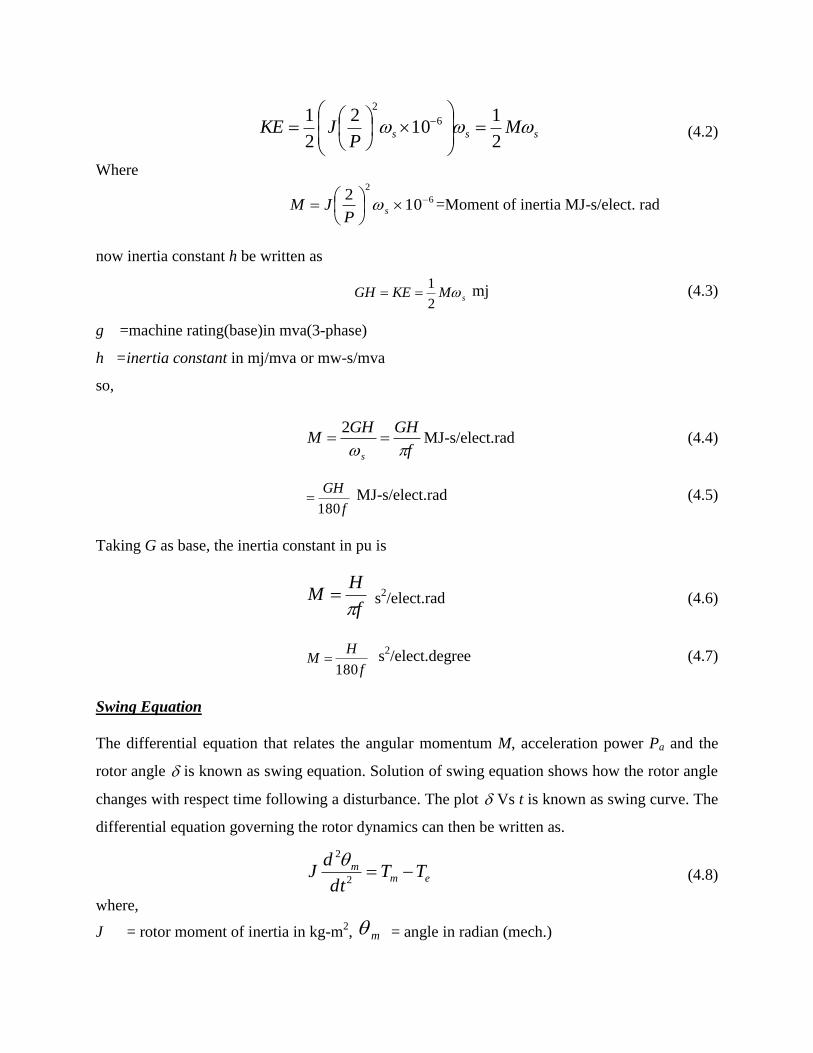
sss MP
JKE 2
110
2
2
1 6
2
(4.2)
Where
6
2
102
s
PJM =Moment of inertia MJ-s/elect. rad
now inertia constant h be written as
sMKEGH 2
1 mj (4.3)
g =machine rating(base)in mva(3-phase)
h =inertia constant in mj/mva or mw-s/mva
so,
f
GHGHM
s
2MJ-s/elect.rad (4.4)
f
GH
180 MJ-s/elect.rad (4.5)
Taking G as base, the inertia constant in pu is
f
HM
s
2/elect.rad (4.6)
f
HM
180 s
2/elect.degree (4.7)
Swing Equation
The differential equation that relates the angular momentum M, acceleration power Pa and the
rotor angle is known as swing equation. Solution of swing equation shows how the rotor angle
changes with respect time following a disturbance. The plot Vs t is known as swing curve. The
differential equation governing the rotor dynamics can then be written as.
emm TT
dt
dJ
2
2 (4.8)
where,
J = rotor moment of inertia in kg-m2, m
= angle in radian (mech.)
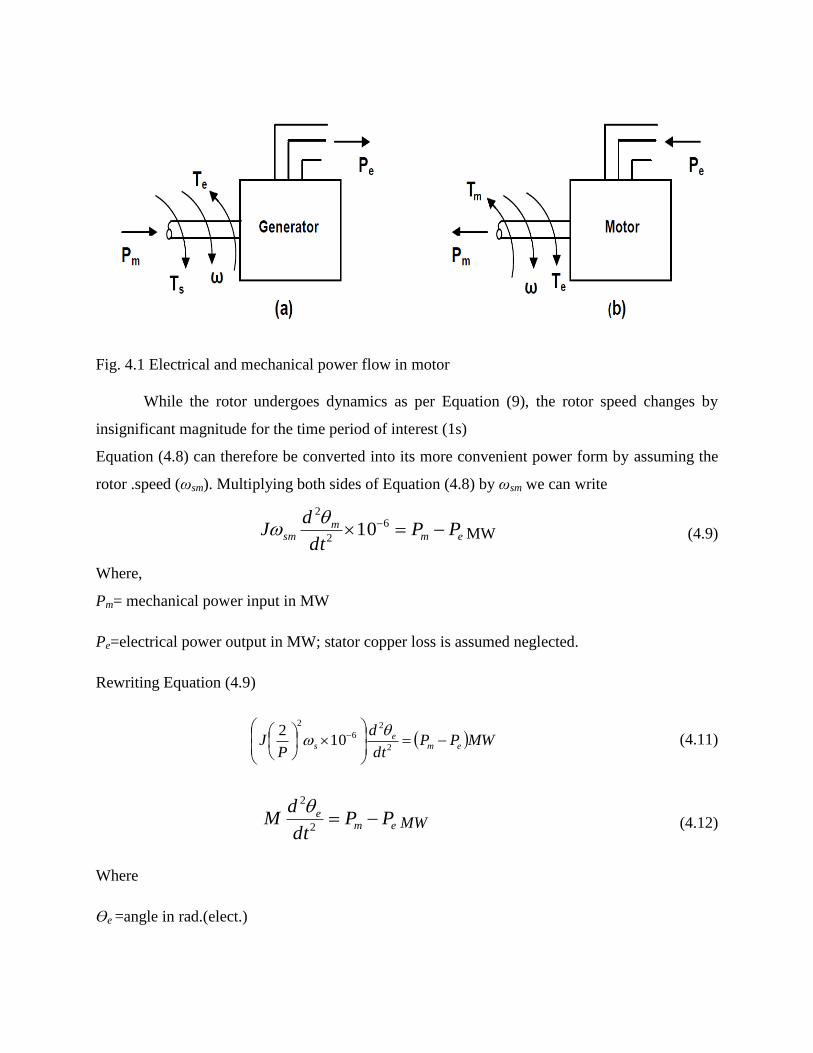
Fig. 4.1 Electrical and mechanical power flow in motor
While the rotor undergoes dynamics as per Equation (9), the rotor speed changes by
insignificant magnitude for the time period of interest (1s)
Equation (4.8) can therefore be converted into its more convenient power form by assuming the
rotor .speed (ωsm). Multiplying both sides of Equation (4.8) by ωsm we can write
emm
sm PPdt
dJ 6
2
2
10
MW (4.9)
Where,
Pm= mechanical power input in MW
Pe=electrical power output in MW; stator copper loss is assumed neglected.
Rewriting Equation (4.9)
MWPPdt
d
PJ em
es
2
26
2
102
(4.11)
eme PP
dt
dM
2
2MW (4.12)
Where
ϴe =angle in rad.(elect.)
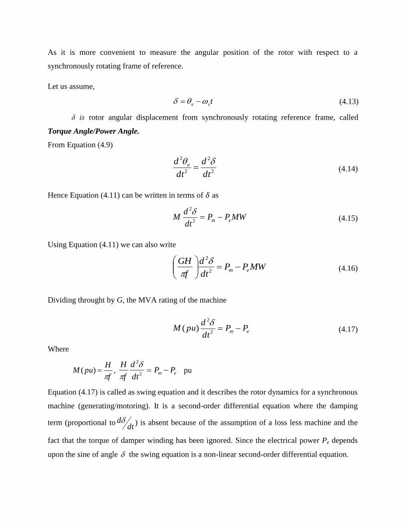
As it is more convenient to measure the angular position of the rotor with respect to a
synchronously rotating frame of reference.
Let us assume,
tse (4.13)
δ is rotor angular displacement from synchronously rotating reference frame, called
Torque Angle/Power Angle.
From Equation (4.9)
2
2
2
2
dt
d
dt
d e (4.14)
Hence Equation (4.11) can be written in terms of 𝛿 as
MWPPdt
dM em
2
2 (4.15)
Using Equation (4.11) we can also write
MWPPdt
d
f
GHem
2
2
(4.16)
Dividing throught by G, the MVA rating of the machine
em PPdt
dpuM
2
2
)(
(4.17)
Where
f
HpuM
)( , em PP
dt
d
f
H
2
2
pu
Equation (4.17) is called as swing equation and it describes the rotor dynamics for a synchronous
machine (generating/motoring). It is a second-order differential equation where the damping
term (proportional todt
d ) is absent because of the assumption of a loss less machine and the
fact that the torque of damper winding has been ignored. Since the electrical power Pe depends
upon the sine of angle the swing equation is a non-linear second-order differential equation.

Multi-Machine System
In a multi-machine system a common system base must be chosen
Let
Gmach=machine rating (base)
Gsystem=system base
Equation(18) can then be written as
system
mach
em
mach
system
mach
G
GPP
dt
d
f
H
G
G)(
2
2
Or em
systemPP
dt
d
f
H
2
2
pu in system base. (4.18)
Where
system
machmachsystem
G
GHH (4.19)
Consider the swing equations of two machines or a common system base.
112
1
2
1
em PPdt
d
f
H
pu (4.20)
222
2
2
2
em PPdt
d
f
H
pu (4.21)
Since the machine rotors swings together (coherently or in unison)
21
Adding Equation (4.20) and (4.21)
em
eqPP
dt
d
f
H
2
2
(4.22)
Where
21 mmm PPP
21 eee PPP
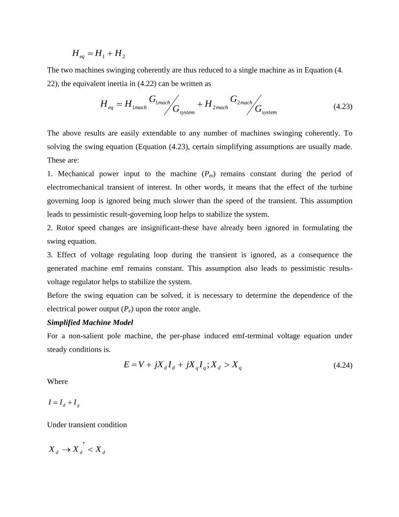
21 HHHeq
The two machines swinging coherently are thus reduced to a single machine as in Equation (4.
22), the equivalent inertia in (4.22) can be written as
system
machmach
system
machmacheq G
GH
GG
HH 22
11 (4.23)
The above results are easily extendable to any number of machines swinging coherently. To
solving the swing equation (Equation (4.23), certain simplifying assumptions are usually made.
These are:
1. Mechanical power input to the machine (Pm) remains constant during the period of
electromechanical transient of interest. In other words, it means that the effect of the turbine
governing loop is ignored being much slower than the speed of the transient. This assumption
leads to pessimistic result-governing loop helps to stabilize the system.
2. Rotor speed changes are insignificant-these have already been ignored in formulating the
swing equation.
3. Effect of voltage regulating loop during the transient is ignored, as a consequence the
generated machine emf remains constant. This assumption also leads to pessimistic results-
voltage regulator helps to stabilize the system.
Before the swing equation can be solved, it is necessary to determine the dependence of the
electrical power output (Pe) upon the rotor angle.
Simplified Machine Model
For a non-salient pole machine, the per-phase induced emf-terminal voltage equation under
steady conditions is.
qdqqdd XXIjXIjXVE ; (4.24)
Where
gd III
Under transient condition
ddd XXX
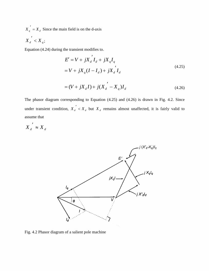
dq XX
Since the main field is on the d-axis
qd XX
;
Equation (4.24) during the transient modifies to.
dddq
qqdd
IjXIIjXV
IjXIjXVE
)( (4.25)
dqdd IXXjIjXV )()(
(4.26)
The phasor diagram corresponding to Equation (4.25) and (4.26) is drawn in Fig. 4.2. Since
under transient condition, dd XX
but dX remains almost unaffected, it is fairly valid to
assume that
dd XX
Fig. 4.2 Phasor diagram of a salient pole machine
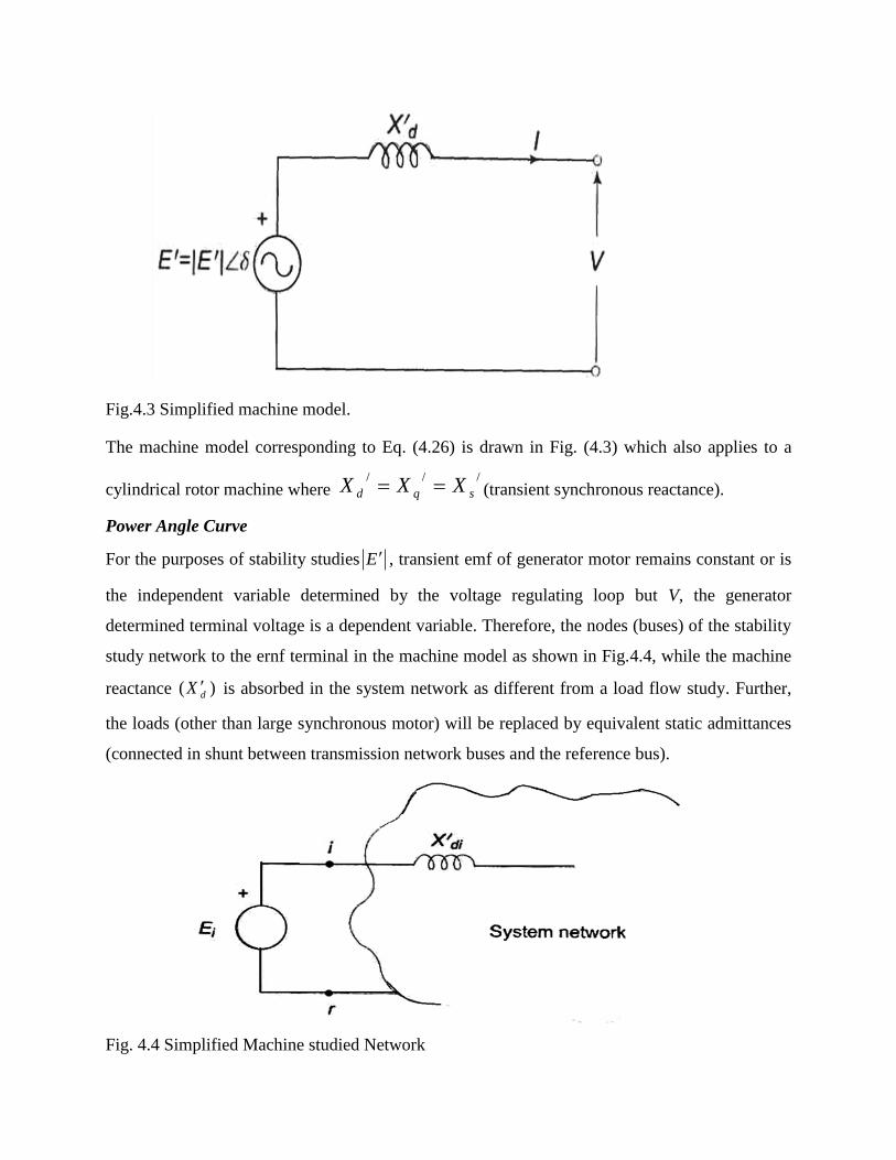
Fig.4.3 Simplified machine model.
The machine model corresponding to Eq. (4.26) is drawn in Fig. (4.3) which also applies to a
cylindrical rotor machine where ///
sqd XXX (transient synchronous reactance).
Power Angle Curve
For the purposes of stability studies E , transient emf of generator motor remains constant or is
the independent variable determined by the voltage regulating loop but V, the generator
determined terminal voltage is a dependent variable. Therefore, the nodes (buses) of the stability
study network to the ernf terminal in the machine model as shown in Fig.4.4, while the machine
reactance )( dX is absorbed in the system network as different from a load flow study. Further,
the loads (other than large synchronous motor) will be replaced by equivalent static admittances
(connected in shunt between transmission network buses and the reference bus).
Fig. 4.4 Simplified Machine studied Network
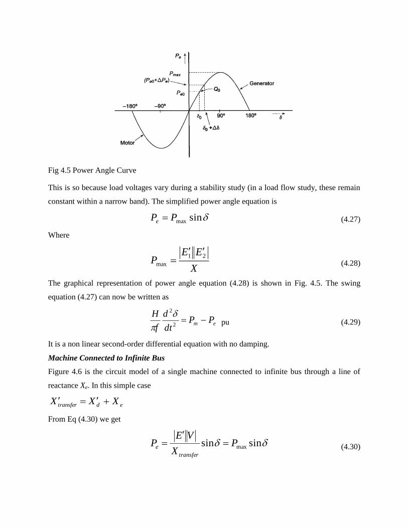
Fig 4.5 Power Angle Curve
This is so because load voltages vary during a stability study (in a load flow study, these remain
constant within a narrow band). The simplified power angle equation is
sinmaxPPe (4.27)
Where
X
EEP
21
max
(4.28)
The graphical representation of power angle equation (4.28) is shown in Fig. 4.5. The swing
equation (4.27) can now be written as
em PPdt
d
f
H
2
2
pu (4.29)
It is a non linear second-order differential equation with no damping.
Machine Connected to Infinite Bus
Figure 4.6 is the circuit model of a single machine connected to infinite bus through a line of
reactance Xe. In this simple case
edtransfer XXX
From Eq (4.30) we get
sinsin maxPX
VEP
transfer
e
(4.30)
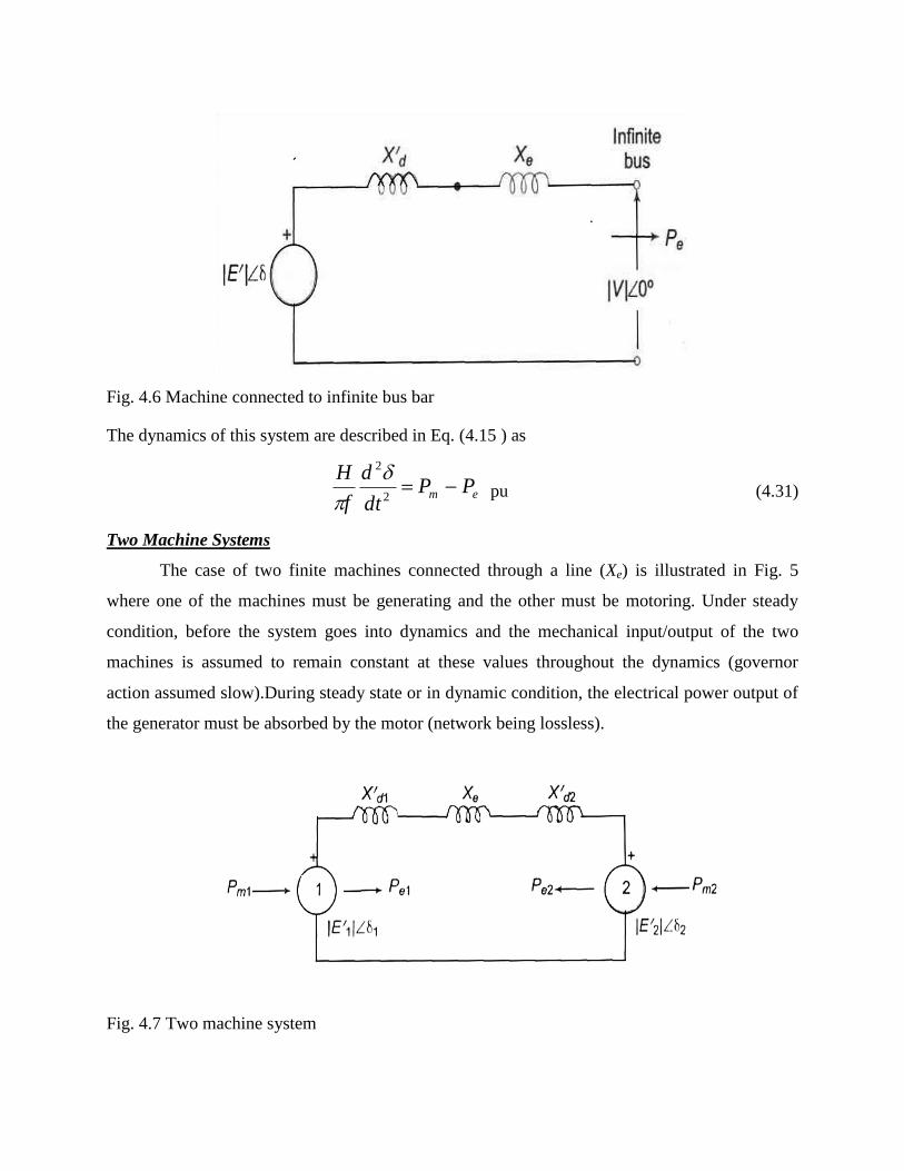
Fig. 4.6 Machine connected to infinite bus bar
The dynamics of this system are described in Eq. (4.15 ) as
em PPdt
d
f
H
2
2
pu (4.31)
Two Machine Systems
The case of two finite machines connected through a line (Xe) is illustrated in Fig. 5
where one of the machines must be generating and the other must be motoring. Under steady
condition, before the system goes into dynamics and the mechanical input/output of the two
machines is assumed to remain constant at these values throughout the dynamics (governor
action assumed slow).During steady state or in dynamic condition, the electrical power output of
the generator must be absorbed by the motor (network being lossless).
Fig. 4.7 Two machine system
Thus at all time
mmm PPP 21 (4.32)
eeme PPP 21 (4.33)
The swing equations for the two machines can now be written as
11
11
2
1
2
H
PPf
H
PPf
dt
d emem
(4.34)
And
11
22
2
2
2
H
PPf
H
PPf
dt
d meem
(4.35)
Subtracting Eq. (36) from Eq. (35)
)()(
21
21
2
21
2
em PPHH
HHf
dt
d
(4.36)
Or em
eqPP
dt
d
f
H
2
2
(4.37)
Where 21
21
21
HH
HHH eq (4.38)
The electrical power interchange is given by expression.
sin21
21
ded
eXXX
EEP
(4.39)
The swing equation Eq. (4.35) and the power angle equation Eq. (4.39) have the same form as
for a single machine connected to infinite bus. Thus a two-machine system is equivalent to a
single machine connected to infinite bus. Because of this, the single-machine (connected to
infinite bus) system would be studied here.
Steady State Stability
The steady state stability limit of a particular circuit of a power system is defined as the
maximum power that can be transmitted to the receiving end without loss of synchronism.
Consider the simple system of Fig. 4.7 whose dynamics is described by equations
MWPPdt
dM em
e 2
2 (4.40)
f
HM
in pu system (4.41)
And,
sinsin maxPX
VEP
d
e (4.42)
For determination of steady state stability, the direct axis reactance (Xd) and, voltage behind Xd
are used in the above equations. Let the system be operating with steady power transfer of
Pe0=Pm with torque angle 0 as indicated in the figure. Assume a small increment P in the
electric power with the input from the prime mover remaining fixed at Pm (governor response is
slow compared to the speed of energy dynamics), causing the torque angle to change to
)( 0 . Linearizing about the operating point Q0 (Pe0, 0 ) we can written as.
0
ee
PP
The excursions of are then described by
0
0
)(
0
2
0
2
2
02
2
e
e
eeem
PMp
or
P
dt
dM
or
PPPPdt
dM
(4.43)
Where
dt
dp
The system stability to small change is determined from the characteristic equation.
00
2
ep
Mp
Its two roots are
2
1
M
p
p
e
As long as 0
ep it positive, the roots are purely imaginary and conjugate and the system
behaviour is oscillatory about 0 . Line resistance and damper windings of machine, which have
been ignored in the above modelling, cause the system oscillations to decay. The system is
therefore stable for a small increment in power so long as
00
ep (4.44)
When 0
ep , is negative, the roots are real, one positive and the other negative but of equal
magnitude. The torque angle therefore increases without bound upon occurrence of a small
power increment (disturbance) and the synchronism is soon lost. The system is therefore unstable
for

00
ep (4.45)
0
ep is known as synchronizing coefficient. This is also called stiffness (electrical) of
synchronous machine.
Assuming |E| and |V| to remain constant, the system is unstable, if
0cos 0 X
VE
900 (4.46)
The maximum power that can be transmitted without loss of stability (steady state) occurs for
900 (4.47)
X
VEP max (4.48)
If the system is operating below the limit of steady stability condition (Eq.4.48), it may
continue to oscillate for a long time if the damping is low. Persistent oscillations are a threat to
system security. The study of system damping is the study of dynamical stability.
The above procedure is also applicable for complex systems wherein governor action and
excitation control are also accounted for. The describing differential equation is linerized about
the operating point. Condition for steady state stability is then determined from the
corresponding characteristic equation (which now is of order higher than two).
It was assumed in the above account that the internal machine voltage |E| remains
constant (i.e., excitation is held constant). The result is that as loading increases, the terminal
voltage |Vt| dips heavily which cannot be tolerated in practice. Therefore, we must consider the
steady state stability limit by assuming that excitation is adjusted for every load increase to keep
|Vt| constant. This is how the system will be operated practically. It may be understood that we
are still not considering the effect of automatic excitation control.

Some Comment on Steady State Stability
Knowledge of steady state stability limit is important for various reasons. A system can
be operated above its transient stability limit but not above its steady state limit. Now, with
increased fault clearing speeds, it is possible to make the transient limit closely approach the
steady state limit.
As is clear from Eq. (4.50), the methods of improving steady state stability limit of a
system are to reduce X and increase either or both |E| and |V|. If the transmission lines are of
sufficiently high reactance, the stability limit can be raised by using two parallel lines which
incidentally also increases the reliability of the system. Series capacitors are sometimes
employed in lines to get better voltage regulation and to raise the stability limit by decreasing the
line reactance. Higher excitation voltages and quick excitation system are also employed to
improve the stability limit.
Transient Stability
The dynamics of a single synchronous machine connected to infinite bus bars is governed by the
nonlinear differential equation
sin
sin
max2
2
max
2
2
PPdt
dM
or
PP
where
PPdt
dM
m
e
em
(4.49)
As said earlier, this equation is known as the swing equation. No closed form solution
exists for swing equation except for the simple case Pm = 0 (not a practical case) which involves
elliptical integrals. For small disturbance (say, gradual loading), the equation can be linearised
leading to the concept of steady state stability where a unique criterion of stability 0 ep
could be established. No generalized criteria are available for determining system stability with
large disturbances (called transient stability). The practical approach to the transient stability
problem is therefore to list all important severe disturbances along with their possible locations
to which the system is likely to be subjected according to the experience and judgement of the
power system analyst. Numerical solution of the swing equation (or equations for a multi-
machine case) is then obtained in the presence of such disturbances giving a plot of Vs t called
the swing curve. If starts to decrease after reaching a maximum value, it is normally assumed
that the system is stable and the oscillation of around the equilibrium point will decay and
finally die out. As already pointed out in the introduction, important severe disturbances are a
short circuit or a sudden loss of load.
For ease of analysis certain assumptions and simplifications are always made (some of
these have already been made in arriving at the swing equation (Eq. 4.49). All the assumptions
are listed, below along with their justification and consequences upon accuracy of results.
1. Transmission line as well as synchronous machine resistance is ignored. This leads to
pessimistic result as resistance introduces damping term in the swing equation which helps
stability.
2. Damping term contributed by synchronous machine damper windings is ignored. This also
leads to pessimistic results for the transient stability limit.
3. Rotor speed is assumed to be synchronous. In fact it varies insignificantly during the course of
the stability transient.
4. Mechanical input to machine is assumed to remain constant during the transient, i.e.,
regulating action of the generator loop is ignored. This leads to pessimistic results.
5. Voltage behind transient reactance is assumed to remain constant, i.e., action of voltage
regulating loop is ignored. It also leads to pessimistic results.
6. Shunt capacitances are not difficult to account for in a stability study. Where ignored, no
greatly significant error is caused.
7. Loads are modelled as constant admittances. This is a reasonably accurate representation.
Note: Since rotor speed and hence frequency vary insignificantly, the network parameters remain
fixed during a stability study.
A digital computer programme to compute the transient following sudden disturbance
can be suitably modified to include the effect of governor action and excitation control.
Preset day power system are so large that even after lumping of machines (Eq.(24)), the
system remains a multi-machine one. Even then, a simple two machine system greatly aids the
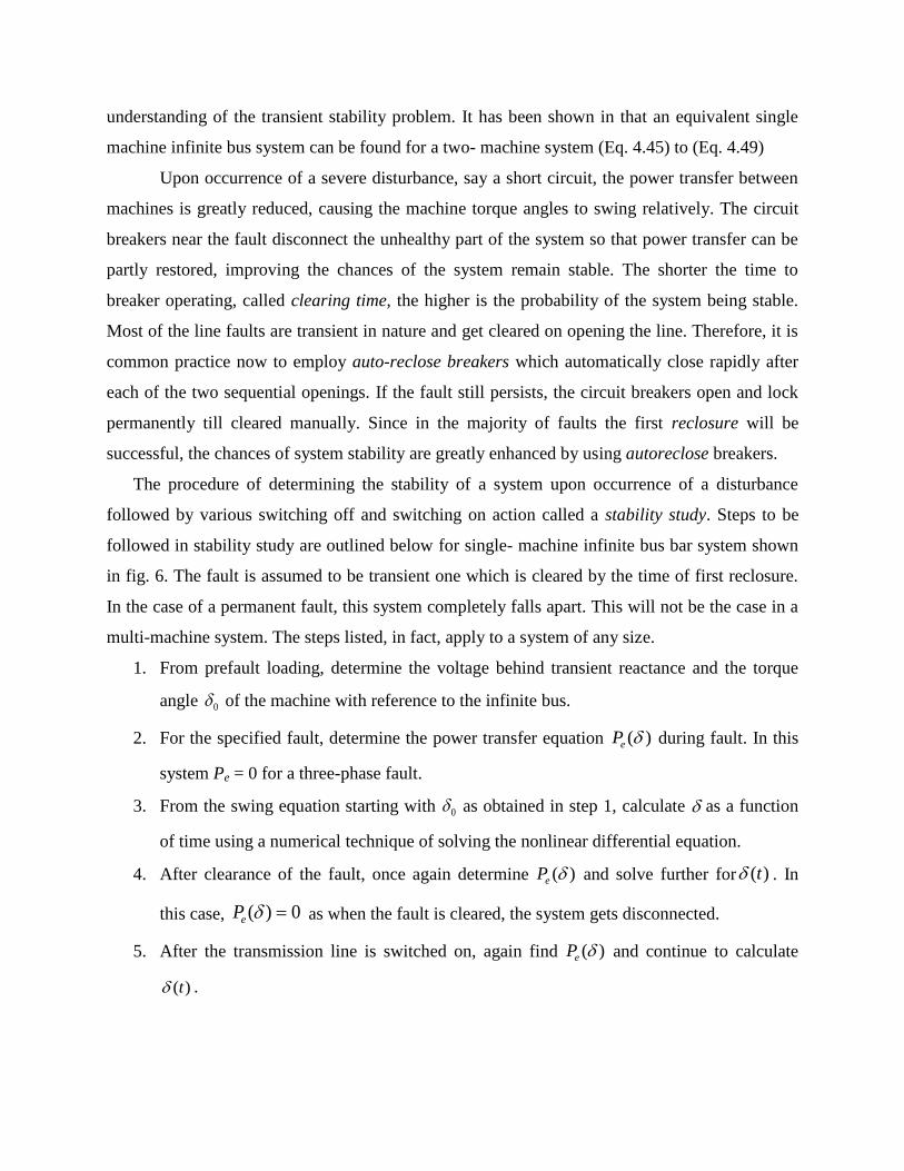
understanding of the transient stability problem. It has been shown in that an equivalent single
machine infinite bus system can be found for a two- machine system (Eq. 4.45) to (Eq. 4.49)
Upon occurrence of a severe disturbance, say a short circuit, the power transfer between
machines is greatly reduced, causing the machine torque angles to swing relatively. The circuit
breakers near the fault disconnect the unhealthy part of the system so that power transfer can be
partly restored, improving the chances of the system remain stable. The shorter the time to
breaker operating, called clearing time, the higher is the probability of the system being stable.
Most of the line faults are transient in nature and get cleared on opening the line. Therefore, it is
common practice now to employ auto-reclose breakers which automatically close rapidly after
each of the two sequential openings. If the fault still persists, the circuit breakers open and lock
permanently till cleared manually. Since in the majority of faults the first reclosure will be
successful, the chances of system stability are greatly enhanced by using autoreclose breakers.
The procedure of determining the stability of a system upon occurrence of a disturbance
followed by various switching off and switching on action called a stability study. Steps to be
followed in stability study are outlined below for single- machine infinite bus bar system shown
in fig. 6. The fault is assumed to be transient one which is cleared by the time of first reclosure.
In the case of a permanent fault, this system completely falls apart. This will not be the case in a
multi-machine system. The steps listed, in fact, apply to a system of any size.
1. From prefault loading, determine the voltage behind transient reactance and the torque
angle 0 of the machine with reference to the infinite bus.
2. For the specified fault, determine the power transfer equation )(eP during fault. In this
system Pe = 0 for a three-phase fault.
3. From the swing equation starting with 0 as obtained in step 1, calculate as a function
of time using a numerical technique of solving the nonlinear differential equation.
4. After clearance of the fault, once again determine )(eP and solve further for )(t . In
this case, 0)( eP as when the fault is cleared, the system gets disconnected.
5. After the transmission line is switched on, again find )(eP and continue to calculate
)(t .
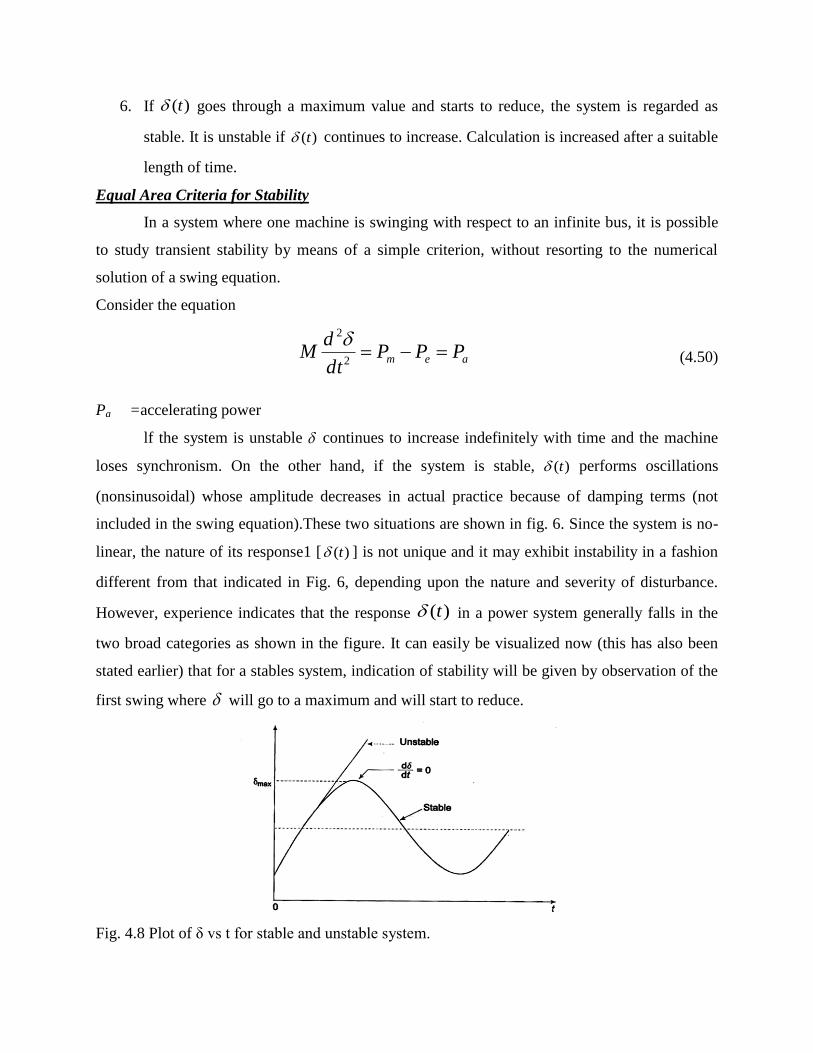
6. If )(t goes through a maximum value and starts to reduce, the system is regarded as
stable. It is unstable if )(t continues to increase. Calculation is increased after a suitable
length of time.
Equal Area Criteria for Stability
In a system where one machine is swinging with respect to an infinite bus, it is possible
to study transient stability by means of a simple criterion, without resorting to the numerical
solution of a swing equation.
Consider the equation
aem PPPdt
dM
2
2 (4.50)
Pa =accelerating power
lf the system is unstable continues to increase indefinitely with time and the machine
loses synchronism. On the other hand, if the system is stable, )(t performs oscillations
(nonsinusoidal) whose amplitude decreases in actual practice because of damping terms (not
included in the swing equation).These two situations are shown in fig. 6. Since the system is no-
linear, the nature of its response1 [ )(t ] is not unique and it may exhibit instability in a fashion
different from that indicated in Fig. 6, depending upon the nature and severity of disturbance.
However, experience indicates that the response )(t in a power system generally falls in the
two broad categories as shown in the figure. It can easily be visualized now (this has also been
stated earlier) that for a stables system, indication of stability will be given by observation of the
first swing where will go to a maximum and will start to reduce.
Fig. 4.8 Plot of δ vs t for stable and unstable system.
This fact can be stated as a stability criterion, that the system is stable if at some time
0dt
d (4.51)
And is unstable, if
0dt
d (4.52)
The stability criterion for power systems stated above can be converted into a simple and easily
applicable form for a single machine infinite bus system. Multiplying both sides of the swing
equation by
dt
d2 , we get
dt
d
M
P
dt
d
dt
d a 22
2
2
Integrating, both sides we get
2
1
2
0
0
2
2
dPMdt
d
or
dPMdt
d
a
a
(4.53)
Where 0 is the initial rotor angle and it begins to swing due to disturbances in the system. From
Eqs. (4.53) and (4.54), the condition for stability can be written as
0
02
0
0
2
1
dP
or
dPM
a
a
(4.54)

Fig.4.9 Pe- δ diagram for sudden increase in mechanical input
The condition of stability can therefore be stated as: the system is stable if the area under Pa
(accelerating power) - curve reduces to zero at some value of . In other words, the positive
(accelerating) area under Pa - curve must equal the negative (decelerating) area and hence the
name „equal area‟ criterion of stability. To illustrate the equal area criterion of stability, we now
consider several types of disturbances that may occur in a single machine infinite bus bar system.
Figure 4.9 shows the transient model of a single machine tied to infinite bus-bar. The electrical
power transmitted is given by
sinsin maxPX
VEP
d
e
Under steady operating condition
0max00 sinPPP em
This is indicated by the point a in the Pe - diagram of Fig. 4.8.
Let the mechanical input to the rotor be suddenly increased to Pm1 (by opening the steam
valve). The accelerating power ema PPP 1 causes the rotor speed to increase )( s and
so does the rotor angle. At angle 1 , 0sin 1max1 PPPP ema (state point at b) but the rotor
angle continues to increase as )( s .Pa now becomes negative (decelerating), the rotor speed
begins to reduce but the angle continues to increase till at angle2 , )( s once again (state
point at c. At c), the-decelerating area A2 equals the accelerating area A1, (areas are shaded), i.e,
0
0
dPa
Since the rotor is decelerating, the speed reduces below s and the rotor angle begins to
reduce. The state point now traverses the eP Vs curve in the opposite direction as indicated by
arrows in Fig. 8.It is easily seen that the system oscillates about the new steady state point b
)( 1 with angle excursion up to 0 and 2 on the two sides. These oscillations are similar to
the simple harmonic motion of an inertia-spring system except that these are not sinusoidal.
As the oscillations decay out because of inherent system damping (not modelled), the
system settles to the new steady state where
1max1 sinPPP em
From Fig. 12.20, areas A1=A2 are given by
dPPA
or
dPPA
me
em
0
0
0
0
)(
)(
11
11
For the system to be stable, it should be possible to find angle 2 such that A1=A2. As Pm1 is
increased, a limiting condition is finally reached when A1 equals the area above the Pm1 line as
shown in Fig 4.10.Under this condition, 2 acquires the maximum value such that
max
11
1max2 sinP
Pm (4.55)
Any further increase in Pm1, means that the area available for A2 is less than A1, so that the excess
kinetic energy causes to increase beyond point c and the decelerating power changes over to
accelerating power, with the system consequently becoming unstable.

Fig. 4.10 Limiting case of transient stability with mechanical input suddenly increased
It has thus been shown by use of the equal area criterion that there-is an upper limit to sudden
increase in mechanical input ( 01 mm PP ), for the system in question to remain stable'
It may be noted from Fig. 9 that the system will remain stable even though the rotor may
oscillate beyond90 , so long as the equal area criteria is met. The condition of
90 is
meant for use in steady state stability only and does not apply to the transient stability case.
Effect of Clearing Time on Stability
Let the system of Fig. 4.9 be operating with mechanical input Pm at a steady angle of
(Pm=Pe) as shown by the point a on the Pe Vs diagram of Fig. 4.10. If a 3-phase fault occurs at
the point P of the outgoing radial line, the electrical output of the generator instantly reduces to
zero, i.e., Pe = 0 and the state point drops to b. The acceleration area A1 begins to increase and so
does the rotor angle while the state point moves along bc. At time tc corresponding to angle c ,
the faulted line is cleared by the opening of the line circuit breaker. The values of tc and c are
respectively known as clearing time and, clearing angle. The system once again becomes
healthy and transmits sinmaxPPe i.e. the state point shifts to d on the original Pe Vs curve.
The rotor now decelerates and the decelerating area A2, begins while the state point moves
along de. If an angle 1 can be found such that A2=A1, the system is found to be stable. The
system finally settles down to the steady operating point a in an oscillatory manner because of
inherent damping.

Fig. 4.10 Limiting case of transient stability with critical angle
The value of clearing time corresponding to a clearing angle can be established only by
numerical integration except in this simple case. The equal area criterion therefore gives only
qualitative answer to system stability as the time when the breaker should be opened is hard to
establish.
As the clearing of the faulty line is delayed, A1 increases and so does 1 , to find A2=A1
till max1 as shown in Fig. 4.10. For a clearing time (or angle) larger than this value, the
system would be unstable as A2<A. The maximum allowable value of the clearing time and angle
for the system to remain stable are known respectively as critical clearing time and angle.
For this simple case (Pe=0 during fault), explicit relationships for c (critical) and tc
(critical) are established below. All angles are in radians.
It is easily seen from Fig.4.10
0max (4.56)
0max sinPP
and
m (4.57)

)()cos(cos
)sin(
)()0(
maxmax
max2
01
max
0
crmmcr
m
crmm
PP
dPPA
and
PdPA
Now
cr
cr
For the system to be stable, A2=A1 which gives
max0max
max
cos)(cos P
Pmcr (4.58)
Where
cr =critical clearing angle.
Substituting Eq. (58) and (59) in Eq.(60), we get
]cossin)2[(cos 000
1
cr (4.59)
During the period the fault is persisting, the swing equation is
;2
2
mPH
f
dt
d where 0eP (4.60)
Integrating twice
0
2
2
tP
H
fm
Or 0
2
2
crmcr tP
H
f (4.61)
Where
tcr =critical clearing time.
cr =critical clearing angle
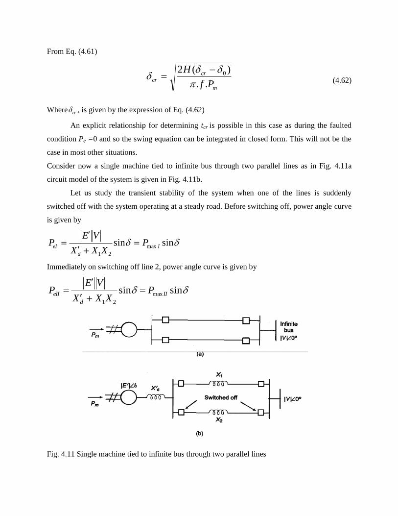
From Eq. (4.61)
m
crcr
Pf
H
..
)(2 0
(4.62)
Where cr , is given by the expression of Eq. (4.62)
An explicit relationship for determining tcr is possible in this case as during the faulted
condition Pe =0 and so the swing equation can be integrated in closed form. This will not be the
case in most other situations.
Consider now a single machine tied to infinite bus through two parallel lines as in Fig. 4.11a
circuit model of the system is given in Fig. 4.11b.
Let us study the transient stability of the system when one of the lines is suddenly
switched off with the system operating at a steady road. Before switching off, power angle curve
is given by
sinsin max
21
I
d
eI PXXX
VEP
Immediately on switching off line 2, power angle curve is given by
sinsin max
21
II
d
eII PXXX
VEP
Fig. 4.11 Single machine tied to infinite bus through two parallel lines

Fig. 4.12 Equal area criterion applied to the opening of one of the two lines in parallel
Both these curves are plotted in Fig. 4.12, wherein PmaxII < PmaxI as )||()( 211 XXXXX dd
.The system is operating initially with a steady power transfer Pe=Pm at a torque angle 0 on
curve I. Immediately on switching off line 2, the electrical operating point shifts to curve II
(point b). Accelerating energy corresponding to area A1 is put into rotor followed by decelerating
energy for 01 . Assuming that an area A2 corresponding to decelerating energy (energy out of
rotor) can be found such that A1 = A2, the system will be stable and will finally operate at c
corresponding to a new, rotor angle 11 . This is so because a single line offers larger
reactance and larger rotor angle is needed to transfer the same steady power.
It is also easy to see that if the steady load is increased (line Pm is shifted upward in Fig. 4.12, a
limit is finally reached beyond which decelerating area equal to A1 cannot be found and
therefore, the system behaves as an unstable one, For the limiting case of stability, 1 has
maximum value given by
c max1
This is the same condition as in the previous example.
We shall assume the fault to be a three-phase one. Before the occurrence of a fault, the power
angle curve is given by
sinsin max
21
I
d
eI PXXX
VEP
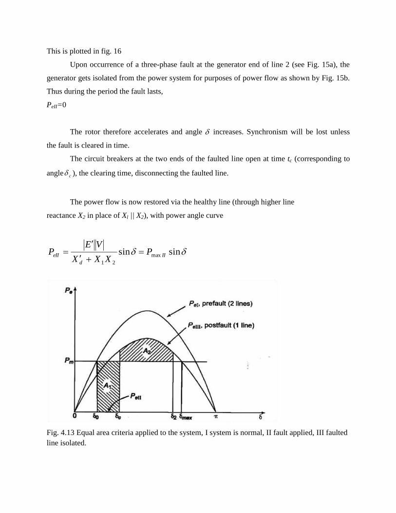
This is plotted in fig. 16
Upon occurrence of a three-phase fault at the generator end of line 2 (see Fig. 15a), the
generator gets isolated from the power system for purposes of power flow as shown by Fig. 15b.
Thus during the period the fault lasts,
PeII=0
The rotor therefore accelerates and angle increases. Synchronism will be lost unless
the fault is cleared in time.
The circuit breakers at the two ends of the faulted line open at time tc (corresponding to
angle c ), the clearing time, disconnecting the faulted line.
The power flow is now restored via the healthy line (through higher line
reactance X2 in place of Xl || X2), with power angle curve
sinsin max
21
II
d
eII PXXX
VEP
Fig. 4.13 Equal area criteria applied to the system, I system is normal, II fault applied, III faulted
line isolated.
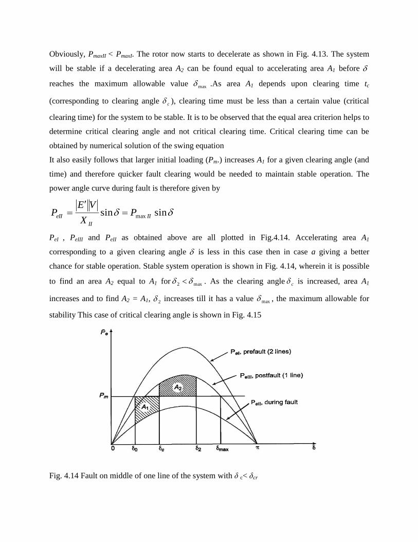
Obviously, PmaxII < PmaxI. The rotor now starts to decelerate as shown in Fig. 4.13. The system
will be stable if a decelerating area A2 can be found equal to accelerating area A1 before
reaches the maximum allowable value max .As area A1 depends upon clearing time tc
(corresponding to clearing angle c ), clearing time must be less than a certain value (critical
clearing time) for the system to be stable. It is to be observed that the equal area criterion helps to
determine critical clearing angle and not critical clearing time. Critical clearing time can be
obtained by numerical solution of the swing equation
It also easily follows that larger initial loading (Pm.) increases A1 for a given clearing angle (and
time) and therefore quicker fault clearing would be needed to maintain stable operation. The
power angle curve during fault is therefore given by
sinsin max II
II
eII PX
VEP
PeI , PeIII and PeII as obtained above are all plotted in Fig.4.14. Accelerating area A1
corresponding to a given clearing angle is less in this case then in case a giving a better
chance for stable operation. Stable system operation is shown in Fig. 4.14, wherein it is possible
to find an area A2 equal to A1 for max2 . As the clearing angle c is increased, area A1
increases and to find A2 = A1, 2 increases till it has a value max , the maximum allowable for
stability This case of critical clearing angle is shown in Fig. 4.15
Fig. 4.14 Fault on middle of one line of the system with δ c< δcr

Fig.4.15 Fault on middle of one line of the system of, case of critical clearing angle
Applying equal area criterion to the case of critical clearing angle of Fig. 4.15 we can write
max
0
)sin()sin( maxmax
cr
cr
dPPdPP mIIIIIm
where
III
m
P
P
max
1
max sin (4.63)
Integrating, we get
or
PP
PP
or
PPPP
crIIIcrm
crIIcrm
mIIIIImcr
cr
0)cos(cos
)cos(cos
0)cos(cos
maxmaxmax
0max0
maxmax
max
0
IIIII
IIIIImcr
PP
PPP
maxmax
maxmax0max0max coscoscos
(4.64)
Critical clearing angle can be calculated from Eq. (4.64) above. The angles in the equation are in
radians. The equation modifies as below if the angle are in degrees.

IIIII
IIIIIm
crPP
PPP
maxmax
maxmax0max0max coscos180cos
If the circuit breakers of line 2 are reclosed successfully (i.e., the fault was a transient one and
therefore vanished on clearing the faulty line), the power transfer once again becomes
sinmax IeIeIV PPP
Since reclosure restores power transfer, the chances of stable operation improve. A case
of stable operation is indicated by Fig. 4.16. For critical clearing angle
I
m
P
P
max
1
max1 sin
max
0
)sin()sin()sin( maxmaxmax
rc
rc
cr
cr
dPPdPPdPP mImIIIIIm
Fig. 4.16 fault in middle of a line of the system
Point To Point Method of Improvement of Transient Stability
In most practical systems, after machine lumping has been done, there are still more than
two machines to be considered from the point of view of system stability. Therefore, there is no
choice but to solve the swing equation of each machine by a numerical technique on the digital
computer. Even in the case of a single machine tied to infinite bus bar, the critical clearing time
cannot be obtained from equal area criterion and we have to make this calculation numerically
through swing equation. There are several sophisticated methods now available for the solution
of the swing equation including the powerful Runge-Kutta method. Here we shall treat the point-
by-point method of solution which is a conventional, approximate method like all numerical
methods but a well tried and proven one. We shall illustrate the point-by-point method for one
machine tied to infinite bus bar. The procedure is, however, general and can be applied to every
machine of a multi-machine system. Consider the swing equation
GHM
M
PPP
Mdt
d a
m
)sin(1
max2
2
Or in p.u f
HM
The solution )(t is obtained at discrete intervals of time with interval spread of At uniform
throughout. Accelerating power and change in speed which are continuous functions of time are
discretized as below:
1. The accelerating power Pa computed at the beginning of an interval is assumed to remain
constant from the middle of the preceding interval to the middle of the interval being considered
as shown in Fig. 4.17.
2.The angular rotor velocity ω= dδ/dt (over and above synchronous velocity ωs) is assumed
constant throughout any interval, at the value computed for the middle of the interval as shown
in fig . 4.17
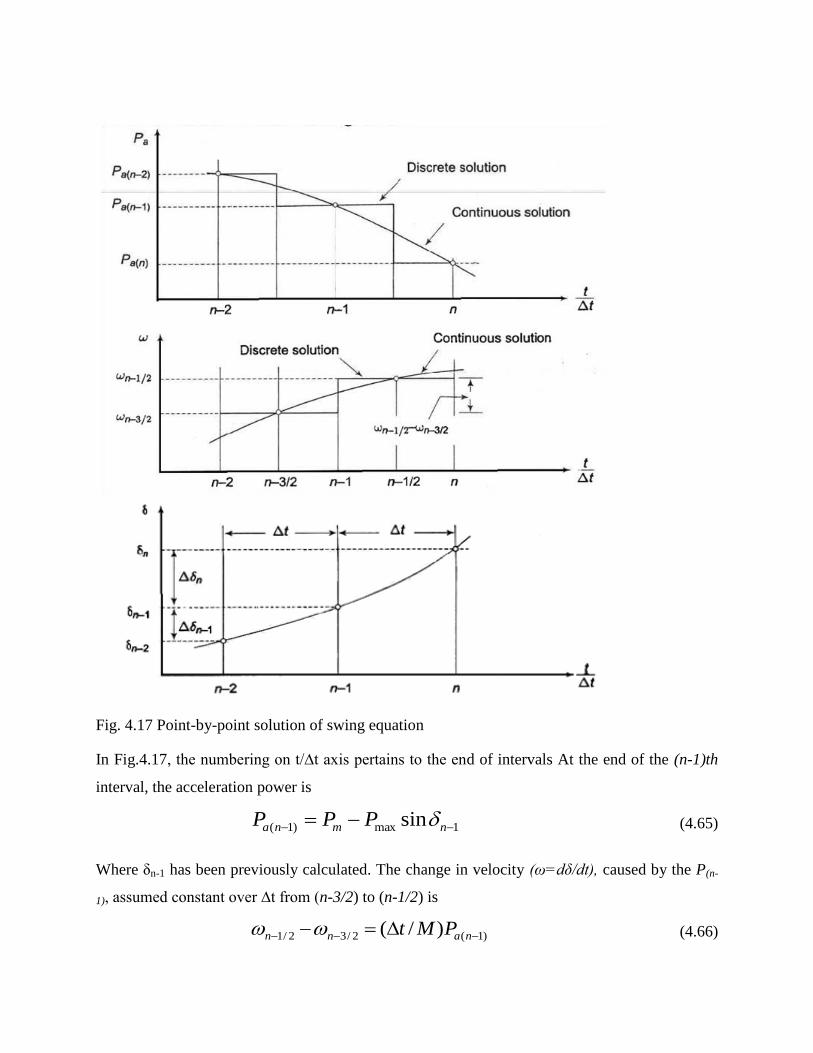
Fig. 4.17 Point-by-point solution of swing equation
In Fig.4.17, the numbering on t/∆t axis pertains to the end of intervals At the end of the (n-1)th
interval, the acceleration power is
1max)1( sin nmna PPP (4.65)
Where δn-1 has been previously calculated. The change in velocity (ω=dδ/dt), caused by the P(n-
1), assumed constant over ∆t from (n-3/2) to (n-1/2) is
)1(2/32/1 )/( nann PMt (4.66)

The change in δ during the (n-1)th interval is
2/321 nnnn t (4.67)
And during the nth interval
2/11 nnnn t (4.68)
Subtracting Eq. (4.67) from Eq. (4.68) and using Eq. (4.65), we get
)1(
2
1
nann P
M
t (4.69)
Using this, we can write
nnn 1 (4.70)
The process of computation is now repeated to obtain Pa(n),∆δn+1.and δ n+1. The time solution in
discrete form is thus carried out over the desired length of time, normally 0.5 s. Continuous form
of solution is obtained by drawing a smooth curve through discrete values as shown in Fig. 4.17.
Greater accuracy of solution can be achieved by reducing the time duration of intervals.
The occurrence or removal of a fault or initiation of any switching event causes a
discontinuity in accelerating power Pa. lf such a discontinuity occurs at the beginning of an
interval, then the average of the values of Pa before and after the discontinuity must be used.
Thus, in computing the increment of angle occurring during the first interval after a fault is
applied at t = 0, Eq. (4.69) becomes
2
)( 02
1
aP
M
t
Where (Pa0+) accelerating power after fault. Immediately before the fault the system is in
steady state, so that Pa0- = 0 and δ0 is a known value. If the fault is cleared at the beginning of the
nth interval, in calculation for this interval one should use for Pa(n-1) the value ½[Pa(n-1)_
+ Pa(n-
1)+], where Pa(n-1)
_is the accelerating power immediately before clearing and Pa(n-1)
+ is that
immediately after clearing the fault. If the discontinuity occurs at the middle of an interval, no
special procedure is needed. The increment of angle during such an interval is calculated, as
usual, from the value of Pa at the beginning of the interval.
Voltage Stability
Power transmission capacity has traditionally been limited by either rotor angle (synchronous)
stability or by thermal loading capabilities. The blackout problem has been linked with transient
stability. Luckily this problem is now not that serious because of fast short circuit clearing,
power excitation systems, and other special stability controls. Electrical companies are now
required to squeeze the maximum possible power through existing networks owing to various
constraints in the construction of generation and transmission facilities.
Voltage (load) stability, however, is now a main issue in planning and operating electric
power systems and is a factor reading to limit power transfers. Voltage stability is concerned
with the ability of a power system to maintain acceptable voltages at all buses in the system
under normal conditions and after being subjected to a disturbance. A power system is said to
have entered a state of voltage instability when a disturbance results in a progressive and
uncontrollable decline in voltage
Inadequate reactive power support from generators and transmission lines leads to
voltage instability or voltage collapses, which have resulted in several major system failures in
the world. They are:
(i) South Florida, USA, system disturbance of 17 May 1985,
(ii) French system disturbances of December 19, 1978 and January 12, 1987, (longer term).
(iii) Swedish system disturbance of December 27, 1983 (longer term, 55 sec).
(iv) Japanese( Tokyo) system disturbance of July 23, 1987 (longer term, 20 min).
(v) NREB grid disturbance in India in 1984 and 1987.
(vi) Belgium, Aug 4, 1982 (longer term, 4.5 min).
(vii) Baltimore, washington DC, USA, 5th July 1990 (longer term, insecure for hours).
Hence, a full understanding of voltage stability phenomena and designing mitigation schemes to
prevent voltage instability is of great value to utilities. Consequently over the last ten years,
utility engineers, consults and researchers have thoroughly studies voltage stability.
Voltage stability covers a wide range of phenomena. Because of this, voltage stability means
different things to different engineers. Voltage instability and voltage collapse are used
somewhat interchangeably by many researchers. Voltage instability or collapse is a faster
dynamic-process. As opposed to angle
Voltage instability or collapse is a faster dynamic-process. As opposed to angle stability,
the dynamics mainly involves the loads and the means for voltage control.
Effective Counter Measures to Prevent or Contain Voltage Instability
(i) Generator terminal voltage should be raised.
(ii) Generator transformer tap value may be increased.
(iii) Q-injection should be carried out at an appropriate location.
(iv) Load-end OLTC (on-load tap changer) should be suitably used.
(v) For under voltage conditions, strategic load shedding should be resorted to.
System reinforcement may be carried out by installing new transmission lines between
generation and load centers. Series and shunt compensation may be carried out and SVCs (static
VAR compensation) may be installed. Practical aspects of Q-flow problems leading to voltage
collapse in EHV lines:
(i) For long lines with uncontrolled buses, receiving end or road voltages increase for light load
conditions and decrease for heavy load conditions.
(ii) For radial transmission lines, if any loss of a line takes place, reactance goes up, I2X loss
increases resulting in increase in voltage drop. This should be suitably compensated by local Q
injection. Of course this involves cost. If there is a shortage of local Q sources, then import of Q
through long line may have to be resorted to. However, this is not desirable
Only the operating points above the critical points represent satisfactory operating
conditions. At the 'knee' of the V-P curve, the voltage drops rapidly with an increase in load
demands. Power-flow solution fails to converge beyond this limit indicating instability.
Operation at or near the stability limit is impractical and a satisfactory operating condition is
ensured by permitting sufficient "power margin".
Voltage Collapse
Voltage collapse is the process by which the sequence of events accompanying voltage
instability leads to unacceptable voltage profile in a significant part of the power system. It may
be manifested in several different ways. Voltage collapse may be characterized as follows:
(i) The initiating event may be due to variety of reasons: Small gradual system change such as
natural increase in system load, or large sudden disturbance such as loss of a generating unit or a
heavily loaded line.

(ii) The crux of the problem is the inability of the system to meet its reactive demands. When
transport of reactive power from neighboring areas is difficult, any change that requires
additional reactive power support may eventually lead to voltage collapse.
(iii) The voltage collapse generally manifests itself as a slow decay of voltage. It is the result of
an accumulative process involving the actions and interactions of many devices, controls, and
protective systems. The time frame of collapse in such cases would be of the order of several
minutes. Voltage collapse is strongly influenced by system conditions and characteristics.
(iv)Reactive compensation can be made most effective by the judicious choice of a mixture of
shunt capacitors, static VAR compensator and possibly synchronous condensers.
Methods of Improving Voltage Stability
i. Voltage stability can be improved by adopting the following means:
ii. Enhancing the localised reactive power support (SVC) is more effective and C-banks are
more economical. FACTS devices or synchronous condenser may also be used,
iii. Compensating the line length reduces net reactance and power flow increases.
iv. Additional transmission line may be erected. I t also improves reliability.
v. Enhancing excitation of generator, system voltage improves and Q is supplied to the
system.
vi. HVDC tie may be used between regional grids.
vii. By resorting to strategic load shedding, voltage goes up as the reactive burden is reduced.