Embed Size (px)
Citation preview

An Algorithm for Improving the Accuracy of Z-Coordinate Determination for USBL Systems
MIKHAIL ARKHIPOV Department of Postgraduate Studies
Technological University of the Mixteca Carretera a Acatlima Km. 2.5, Huajuapan de Leon, Oaxaca
MEXICO [email protected]
Abstract: - This paper presents an approach to resolve the problem of low Z-coordinate determination accuracy for ultra-short baseline (USBL) acoustic systems in which the location measurement of the underwater objects is based on the determination of the distance to the object and the angle object position. The antenna with five receiving elements and different spatial orientation of receiving bases is proposed. It is assumed that the receiving antenna may have the significant inclinations and the orientation of the USBL antenna which is controlled by measuring of the pitch and roll angles. The problem of the low precision Z-coordinate determination is resolved by means of utilizing various spatial orientations of the receiving bases in a modernized five element USBL system. The computer simulation results of the proposed algorithm are presented to demonstrate reliable operation of the algorithm for different angular antenna positions and various locations of the object. The results of the calculation of the errors of the determination of the object coordinates and accuracy evaluation of modernized USBL system are presented. Key-Words: - Ultra-short baseline (USBL) system, underwater object, transponder, carrier coordinate system, local coordinate systems, pitch and roll angles. 1 Introduction The determination of the position of an underwater object with respect to a given reference point is required for the wide range of tasks in ocean engineering. In some cases the accuracy in determining the position of the object may be critical. Within the scope of this task, the design of the methods of adaptation of underwater systems to the variations of operational conditions has a special significance. For some classes of systems, in particular for the underwater navigation and positioning systems, this implies taking into account the conditions of sea surface and inhomogeneity of water. The methods and the systems for determining the position of underwater objects are being constantly developed with a view to improving the reliability and accuracy of object coordinate measurements. During the past few decades the special attention in this class of systems was paid to application of new signal processing techniques and signal filtering. In this paper, we examine a coordinate determination algorithm for the systems designed to measure the location of underwater objects equipped with transponders. The proposed algorithm is focused on resolving the problem of low precision Z-coordinate
determination for ultra-short baseline (USBL) systems. 2 Problem Formulation 2.1 USBL measurement principle To determine the position of the dynamic underwater objects, as a rule, three basic methods are used [1][2]. The first method utilizes the measurement of the distances between the object and the seabed reference points with the known coordinates. The distances are obtained through the measurement of the propagation times of the acoustic pulses emitted by an emitter placed on the object and by the transponders placed on the sea floor. The values of coordinates of transponders and the measured distances from the object to transponders enable us to calculate the coordinates of the object. This method requires at least three bottom transponders and special polygon calibration to determine transponder coordinates. Systems utilizing this method are called long baseline (LBL) systems. The second method to determine the position of underwater objects uses the measurement of the distance to the object and its angular location. The measuring system is located in
WSEAS TRANSACTIONS on SYSTEMS
Mikhail Arkhipov
ISSN: 1109-2777 298 Issue 4, Volume 7, April 2008

a reference point, while the underwater object is equipped with the transponder. The distance being determined by the measurement of the values of propagation times of the requested impulse of the system and the response transponder pulse. The angular location of the object is determined by the measurement of the delays of the envelope of the transponder pulse on the elements of the receiving antenna. The minimum number of elements of the receiving antenna is three. As a rule, these three elements are placed in a horizontal plane and form two receiving bases (one of the elements is utilized for both bases), two receiving bases form a right angle. These types of systems are called short baseline (SBL) systems. In this paper we describe coordinate determination algorithm for ultra-short baseline (USBL) acoustic systems, which employs the same principle as SBL systems: the distance to the object and its angular location are measured. Unlike the SBL method (where the delays of the front of the transponder impulse are measured), the phase difference of the pulse carrier frequency on the elements of the receiving antenna is measured. For an unambiguous coordinate determination, the size of the receiving bases must be less than half of the acoustic wavelength of the transponder pulse carrier frequency. Before representing the designed coordinate determination algorithm, we will consider the technique of the coordinate determination for the case of the three element USBL system. Let system Σ=(0,x,y,z) be the left hand Cartesian coordinate system. Let the plane of the USBL antenna be aligned with the (x,y) coordinate plane and the z-axis has the downwards direction. We align the origin O of coordinate system with the receiving element 2. We align the x-axis with the receiving
z
y
x
R
P(X,Y,Z)
αγ
β
12
3
O dd
Object(with transponder)
Interrogationimpulse
Replypulse
Fig.1 Three element USBL antenna and the point P in introduced coordinate system
base 3-2 and the y-axis with the receiving base 1-2. Three element USBL antenna and the point P in the introduced coordinate system Σ=(0,x,y,z) are represented in Fig.1. Let the size of the receiving bases be d. Now we can define the coordinates of the point P(X,Y,Z). The time delays τ12 and τ32 of the signal on the outputs of the elements of the base 1-2 and the base 3-2 (it is supposed that R>>d) can be expressed as:
12cosdc
βτ = , 32
cosdc
ατ = , (1)
where c is the speed of the sound in the water. With d/c defined as τd we can write the direction cosines cosα and cosβ:
32cos dα τ τ= , 12cos dβ τ τ= . (2) The third direction cosine is:
( ) ( )2 2
32 121cos d dγ τ τ τ τ− −= . (3)
Cartesian coordinates of the point P define as:
cosX R α= , cosY R β= , cosZ R γ= . (4) Azimuth angle φ of point P can be obtained from expression:
(cos cos )arctgϕ α β= . (5) 2.2 Accuracy problem The object position accuracy in real marine conditions is the key to the development of the USBL systems. There are four main factors that can cause errors in the measurement of the position of underwater objects by the USBL systems. These factors are as follows: the inhomogeneity of the propagation medium and in particularly the phenomenon of the acoustic refraction in the water; the phenomenon of multipath interference due to multiple reflections of acoustic rays from the sea surface, the sea floor and the carrier hull; the phenomenon of diffraction of the acoustic waves in the body of the receiving antenna; the instability of the position of the receiving antenna [3][4]. The errors caused by the first factor can be considered as a systematic component of the errors of the coordinate measurements. These errors can be taken into account by means of the calculation of the real trajectories of acoustic rays with the
WSEAS TRANSACTIONS on SYSTEMS Mikhail Arkhipov
ISSN: 1109-2777 299 Issue 4, Volume 7, April 2008

subsequent determination of the real position of the object [5]. The second factor can be resolved by suppressing the signals coming from unexpected directions and by taking into account that these signals have a time lag relative to the first incoming impulse [6]. To improve the accuracy of USBL systems various special signal processing techniques were designed. In particular the chirp signals and greater inter-element array separation [7] were used. Also the acoustic digital spread spectrum [8] and modulated Barker-coded signals [9] were applied. In [10] the USBL system with frequency-hopped pulses was investigated. Reduction of impact of the third factor can be achieved by the improvement of antenna body construction and by optimization of the choice of size of sensors and operating frequency [11]. One of the methods of reducing the influence of antenna body diffraction errors is to use the redundant receiving elements by means of the increase of the number of elements of the receiving antenna. The fourth factor can be considered as a cause of the systematic errors as in the first one. This error component can be eliminated by measuring the inclination of the USBL antenna in the moment of measuring the antenna time delays and the following recalculation of object position [12]. In this paper we will concentrate on the fourth aspect of the accuracy problem. We also solve the problem of low precision in coordinate determination for the case the object found in the plane of receiving bases. The method to resolve specified problems includes the increase of the number of receiving bases of the USBL antenna and the design of an algorithm that enables the system to take into account the occasional inclination of the USBL antenna. It is assumed that the space orientation of the antenna is controlled by the measurement of the pitch and roll angles. Furthermore, in this paper we also assume that the propagation medium is homogeneous and multipath interference is absent. 3 Problem Solution 3.1 Antenna and coordinate systems Before introducing an explanation of the algorithm, some changes in the antenna construction must be made. At first, we add one more element to the antenna array in the horizontal plane. This element is added in such a way that a square is formed (the sides of the square form the receiving bases of the antenna). As result we have four basic three element USBL arrays (see Fig.2, a)).
3 3 3 3 11112 2 2 2
4 4 4 4
3 1
5
2 4
5
5a) decomposition of the receiving antenna on four basicUSBL antennas in horozontal plane
b) decomposition of the receiving antenna on two basicUSBL antennas in two ortogonal vertical planes
3 12
45
Fig.2. The five element receiving antenna and its decomposition on the basic USBL arrays. The second modification of the antenna construction is the aggregation of the fifth element in another horizontal plane. The fifth element is placed underneath the four element USBL antenna plane exactly underneath its geometric center, so that the four obtained inclined bases would be the same size as the size of the horizontal receiving bases. In this case, the USBL system obtains two additional three element basic USBL arrays placed in two orthogonal vertical planes. Finally, we have the five element USBL array. The decomposition of the five element USBL antenna on the six basic USBL antennas is presented in Fig.2. The proposed antenna construction allows the elimination of the known drawback of the USBL systems with only horizontal plane array arrangement: the low accuracy of measuring the vertical coordinate when the object depth is close to the operating depth of the receiving antenna. The receiving antenna orientation and the axis of the USBL system carrier are shown in Fig.3. From hereon in this paper, the carrier is represented by means of its longitudinal l-l' and lateral b-b' axes (the straight arrowed line shows the direction of movement of the carrier). The coordinates of an object are determined in the carrier coordinate system. Let Σ=(0,x,y,z) be the carrier coordinate system with the origin in the point O in such a way that the x-coordinate goes throughout the axis l-l' (the positive direction coincides with the direction of the straight arrowed line) and the y-coordinate goes throughout the axis b-b', and z-axis goes downwards. We will also continue to utilize the earlier introduced basic USBL coordinate system (see Fig.1). We now define it as a local coordinate system.
WSEAS TRANSACTIONS on SYSTEMS Mikhail Arkhipov
ISSN: 1109-2777 300 Issue 4, Volume 7, April 2008

x123
z123
y123
l
b'
bl'
O2 1
3 4
5
xξ123
zξ123
yξ123
ξ
ζ<(x123 ,b)
<(z123 ,b)
<(y123 ,b)
x
y
z
Fig.3. The receiving antenna orientation and the carrier longitudinal and lateral axes. Let Σ123=(0,x123,y123,z123) be the local coordinate system for the basic USBL system with antenna elements 1,2,3. We will later introduce the coordinate systems for the other basic three-element USBL system. 3.2 Calculation expressions In this section, we examine this newly-introduced five element USBL system when the receiving antenna may be in an unstable position. We assume that the USBL system is equipped with the special block to measure the pitch and roll angles of the receiving antenna. Let angles ξ and ζ be pitch and roll angles of the receiving USBL antenna. The case of the pitch inclination of the receiving antenna (rotation of the antenna about the b-b' axis by the angle ξ) is shown in Fig.3. Let USBL123 system be the basic USBL system with receiving elements 1,2,3. If the antenna of USBL123 system has a pitch angle, this signifies the rotation of the coordinate system Σ123=(0,x123,y123,z123) around the axis b-b', with the transformation of the Σ123 =(0,x123,y123,z123) in a new coordinate system Σξ123=(0,xξ123,yξ123,zξ123). For the coordinate system Σ123, we have the following direction cosines for the axis b-b' (see the Fig.3):
123cos ( , ) 2 2x b = − ;
123
cos ( , ) 2 2y b = ;
123
cos ( , ) 0z b = . (6) To obtain the compact expressions for the coordinates, we introduce the following designations for the direction cosines:
123 123
cos ( , )x b η= ;
123 123cos ( , )y b χ= ;
123 123
cos ( , )z b ν= . (7) Let Xξ123, Yξ123, Zξ123 be the coordinates of the object in the coordinate system Σξ123. Knowing the direction cosines for the coordinate system Σ123 and the axis b-b' we can find the coordinates of the object in the new coordinate system Σξ123=(0,xξ123,yξ123,zξ123). The coordinates Xξ123, Yξ123, Zξ123 in the coordinate system Σξ123 are obtained with the formulas [13]:
2123 123 123 123 123 123 123 123 123 123 123
(cos (1 cos )) ( sin (1 cos )) ( sin (1 cos ))X X Y Zξ ξ η ξ ν ξ η χ ξ χ ξ η ν ξ= + − + + − + − + −
2123 123 123 123 123 123 123 123 123 123 123
( sin (1 cos )) (cos (1 cos )) ( sin (1 cos ))Y X Y Zξ ν ξ χ η ξ ξ χ ξ η ξ χ ν ξ= − + − + + − + + −2
123 123 123 123 123 123 123 123 123 123 123( sin (1 cos )) ( sin (1 cos )) (cos (1 cos ))Z X Y Zξ χ ξ η ν ξ η ξ ν χ ξ ξ ν ξ= + − + − + − + + −
(8) This system can be rewritten in the matrix form:
ξ123 123
p = Ap , (9) where: pξ123=[Xξ123,Yξ123,Zξ123]T; p123=[X123,Y123,Z123]T and A is matrix :
2123 123 123 123 123 123 123
2123 123 123 123 123 123 123
123 123 123 123 123 123 123
cos (1 cos ) sin (1 cos ) sin (1 cos )
sin (1 cos ) cos (1 cos ) sin (1 cos )
sin (1 cos ) sin (1 cos ) cos
ξ η ξ ν ξ η χ ξ χ ξ η ν ξ
ν ξ χ η ξ ξ χ ξ η ξ χ ν ξ
χ ξ η ν ξ η ξ ν χ ξ ξ ν
=
+ − + − − + −
− + − + − + −
+ − − + − +
A2 (1 cos )ξ−
(10) Solving the matrix equation (9) we obtain:
-1123 123
ξp = pA . (11) If the antenna of the USBL system, in addition to the pitch angle, has a roll angle ζ, this will transform the coordinate system Σξ123 in a new coordinate system Σξ,ζ123 by the rotation of the coordinate system Σξ123 around the axis l-l'. In the case of the rotation of the coordinate system Σξ123 around the axis l-l' in the roll angle, the direction cosines for the xξ123-axis (base 2-3) and for the yξ123-axis (base 1-2) will be equal. We find the expression of the direction cosine for the xξ123-axis (base 2-3). To obtain this expression we consider the rotation of the base 2-3 around the b-b' axis on the pitch angle ξ (0≤ξ≤90°). The rotation geometry
WSEAS TRANSACTIONS on SYSTEMS Mikhail Arkhipov
ISSN: 1109-2777 301 Issue 4, Volume 7, April 2008

z123l
b' b
l'
O
3
xξ123
ξ
x
y
zx123
<(x123 ,b)
2
3ξ
<(xξ123 ,b)
ξ
m
h
d
n
d
a
a
a
a
a
Fig.4. The rotation geometry of the base 2-3 around the b-b' axis on the pitch angle ξ. of the base 2-3 is shown in Fig.4. In Fig.4 the direction cosine to find is designated as
123cos ( , )x lξ
. By introducing in the figure the set of right-angled triangles with the sides d, a, m, n y h we can write the set of equations:
(sin )h a ξ= ; (1 cos )m a ξ= − ;
2 2 2 2n m a h= + + . From the set of equations we can express n2 through the value a and the angle ξ. Also we can write the n2 through the direction cosine
123cos ( , )x lξ
by applying the cosine law for the triangle with the sides d, a ( 2 2a d= ) and n.
2 2 2
123cos ( , )2 x ln a d ad ξ+ −= .
The direction cosine for the zξ123-axis is determined by pitch angle. Finally, the direction cosines can be expressed as follows:
123cos ( , ) cos 2x lξ ξ= ,
123
cos ( , ) cos 2y lξ ξ= ,
123
cos ( , ) cos( / 2 )z lξ π ξ= − . (12) To obtain compact expressions, we introduce the formulas:
123 123cos ( , )x lξ ξη= ;
123 123
cos ( , )y lξ ξχ= ;
123 123
cos ( , )z lξ ξν= . (13) Now we can find the coordinates Xξ,ζ123, Yξ,ζ123, Zξ,ζ123 in the coordinate system Σξ,ζ123 that were obtained by rotation of the coordinate system Σξ123 around the axis l-l' in roll angle. In matrix form, it will be:
ξ, ξ123 123ςp = Bp , (14)
where: pξ,ζ123=[Xξ,ζ123, Yξ,ζ123, Zξ,ζ123]T; pξ123=[Xξ123,Yξ123,Zξ123]T; and B is matrix:
( )( )
2
123 123 123 123 123 123 1232
123 123 123 123 123 123 123
123 123 123 123 123 1
cos (1 cos ) sin (1 cos ) sin (1 cos )
sin (1 cos ) cos (1 cos ) sin (1 cos )
sin (1 cos ) sin
ξ ξ ξ ξ ξ ξ ξ
ξ ξ ξ ξ ξ ξ ξ
ξ ξ ξ ξ ξ
ζ η ζ ν ζ η χ ζ χ ζ η ν ζ
ν ζ χ η ζ ζ χ ζ η ζ χ ν ζ
χ ζ η ν ζ η ζ ν χ
+ − + − − + −
= − + − + − + −
+ − − +
B
( )223 123(1 cos ) cos (1 cos )ξ ξζ ζ ν ζ
− + −
(15) Solving the matrix equation (14), we obtain:
ξ123 123
-1 ςp = pB . (16) Sustaining (16) in (11), we obtain the coordinates of the object in the basic coordinate system Σ123:
-1 -1123 123
ξ,ςp = A B p . (17) In order to obtain the coordinates of the object in a carrier coordinates system Σ=(0,x,y,z) it is necessary to make one more rotation of the coordinate system Σ123 around the axis z on the angle of 135° (see Fig.3). For the Σ coordinate system, we have the following direction cosines for the z-axis:
cos ( , ) 0x z = ; cos ( , ) 0y z = ; cos ( , ) 1z z = . (18)
To find the coordinates in the carrier coordinate system, we write the matrix equation:
123p = Cp , (19)
where: p123=[X123,Y123,Z123]T; p=[X,Y,Z]T and C is the matrix that realizes rotation of the coordinate system Σ123 around the axis z:
WSEAS TRANSACTIONS on SYSTEMS Mikhail Arkhipov
ISSN: 1109-2777 302 Issue 4, Volume 7, April 2008

2 2 02 2
2 2 02 2
0 0 1
−
− −=
C . (20)
Solving the matrix equation (19), we obtain the coordinates of object in carrier coordinate system:
-1 -1 -1123ξ,ςp = C A B p . (21)
In case of the USBL system with the antenna of five elements, the system consists of six basic USBL systems with six different orientations: USBL123, USBL234, USBL341, USBL412, USBL153 and USBL452. The coordinates of the object are determined individually in each basic USBL system. The USBL123 system differs from the USBL234, USBL341 and USBL412 systems in its own values of the pitch and roll angles and the angle of rotation of each basic three element USBL antenna around the z-axis. The algorithm of coordinate determination for the USBL153 and USBL452 systems is practically the same as for the USBL123 system. It is necessary to make all algorithm steps represented for the USBL123 system, taking into account the corresponding values of the pitch and roll angles. Before the final transformation (to obtain the coordinates in the carrier coordinate system) it is necessary to make one additional rotation of the local coordinate systems to reduce USBL153 and USBL452 systems to the horizontal plane. In order to distinguish the results of the measured coordinates by different basic USBL systems we introduce new designations for the vectors and transformation matrixes:
USBL 123 123 123 123123
ξ,-1 -1 -1 ςp = C A B p ;
USBL 234 234 234 234234
ξ,-1 -1 -1 ςp = C A B p ;
USBL 341 341 341 341341
ξ,-1 -1 -1 ςp = C A B p ;
USBL 412 412 412 412412
ξ,-1 -1 -1 ςp = C A B p ;
USBL 153 153 153 153 153153
ξ,-1 -1 -1 -1 ςp = C D A B p ;
USBL 452 452 452 452 452452
ξ,-1 -1 -1 -1 ςp = C D A B p . (22)
3.3 Problem of Z-coordinate measuring The important part of the algorithm is solving the problem of the low precision of coordinate
determination in cases when an object is found in the plane of receiving bases. We will demonstrate this problem for the case of three element USBL123 system and when the receiving does not have inclination (ξ=0, ζ=0). We will estimate the coordinate determination accuracy of the USBL system. Let X, Y, Z be the true values of the coordinates of the object in the carrier coordinate system Σ=(0,x,y,z). Let R be the true incline distance to the object. Let XUSBL, YUSBL, ZUSBL be the values of the coordinates obtained by means of the developed algorithm (the coordinates of the object are calculated with utilizing of the expression (22) for USBL123 system). The values of the true errors of determination of the coordinates can be written as ∆X=XUSBL-X; ∆Y= YUSBL-Y, ∆Z= ZUSBL-Z. The values of the relative true errors of the coordinates we can write as follows: ∆X/R; ∆Y/R; ∆Z/R. Simulating the situation when the object is located close to the horizontal plane of the receiving USBL antenna we assume the distance to the object R=100m and relative depth Z=5m. In process of the simulation the azimuth angle φ is changing clockwise (if look down on horizontal plane, see Fig.3) from 0° to 360° with 1° step in the (x,y) coordinate plane (zero reading is coincided with x-axis of the Σ=(0,x,y,z) coordinate system, see Fig.3). We can also calculate the spherical coordinates of the object or coordinate vector in spherical coordinate system. This vector can be expressed as follows:
, ,( , ),ξ, T123 123 123 123
R ξ ξς ςς ψ ϕ q = (23) The colatitude angle ψξ,ζ123 in the spherical coordinate system measures the declination from vertical (from z-axis). In our case it is the more practical to use the altitude angle which will characterize the degree of closeness of the object to the plane of the measuring system. The modulus of the altitude angle to the object relatively the USBL123 system plane can be expressed as |ψξ,ζ123 -90°|. The results of the calculation of relative errors and the modulus of attitude angle |ψξ,ζ123 -90°| are shown in Fig.5. From Fig.5 we can note that the accuracy of X- and Y-coordinates determining is good (0.025%) and for Z-coordinate is very poor (the relative errors ∆Z/R in some cases are more than 20 times greater than the ∆X/R, ∆Y/R, the values of relative errors ∆Z/R are changing in diapason from -0.4% to 0.4%). The increasing of the time delay counter frequency can improve the situation, but do not resolve the Z-coordinate accuracy requirement problem,
WSEAS TRANSACTIONS on SYSTEMS Mikhail Arkhipov
ISSN: 1109-2777 303 Issue 4, Volume 7, April 2008

103 (∆
X/R
), 10
3 (∆
Y/R
), 10
3 (∆
Z/R
), |ψξ,ζ 12
3-90°
| , deg
.
4
2
0
-2
-40 90 180 270 360
φ, deg.
• • • • |ψξ,ζ123-90°|
°°°° 103(∆Y/R)
×××× 103(∆X/R)
103(∆Z/R)
Fig.5. Variation of the relative errors of the object coordinates and modulus of the latitude angle to the transponder (object) relatively the USBL123 plane; R=100m; Z=5m; ξ=0°; ζ=0°. especially when the object is located closer to the plane of receiving USBL antenna (for example in the cases of inclination of receiving antenna). The next figure (Fig.6) shows the case when the object is located in the relative depth of 15m (with incline distance R=100m) and the receiving USBL123 antenna has the inclination ((ξ=5°, ζ=-6°). As was expected the relative errors of determination of the Z-coordinate of the object are increased for the angle where the object is found even closer to the receiving antenna plane. From Fig.6 we can note also that when the modulus of the latitude angle is more than some threshold value (we can designate this threshold as ∆lat. angle and elect, for example, the threshold ∆lat. angle=10°) the values of the relative errors ∆Z/R become comparable with the values of X- and Y-coordinates relative errors. In the graph this diapason of azimuth angles (approximately from 50° to 210°) is marked with two vertical lines. The graphs of relative coordinate errors on Fig.6, which were calculated with the first formula (22), show some increase of the Y-coordinates relative errors (in diapason from 300° to 330°), that can be explained by utilizing Z-coordinate (obtained in considering diapason of φ with certain error) in design formula (22). Thus, in fact, the problem of accurate determination of the object coordinates by means of USBL system is the problem of the increase of the Z-coordinate determination accuracy. The construction of antenna with five receiving elements proposed earlier allows the resolution of this problem by using the abundant data obtained with other elemental USBL systems that form the
103 (∆
X/R
), 10
3 (∆
Y/R
), 10
3 (∆
Z /R
), |ψξ,ζ 12
3-90°
| , deg
.
20
10
0
-10
-200 90 180 270 360
φ, deg.
• • • • |ψξ,ζ123-90°|
103(∆Z/R)
×××× 103(∆X/R)
°°°° 103(∆Y/R)
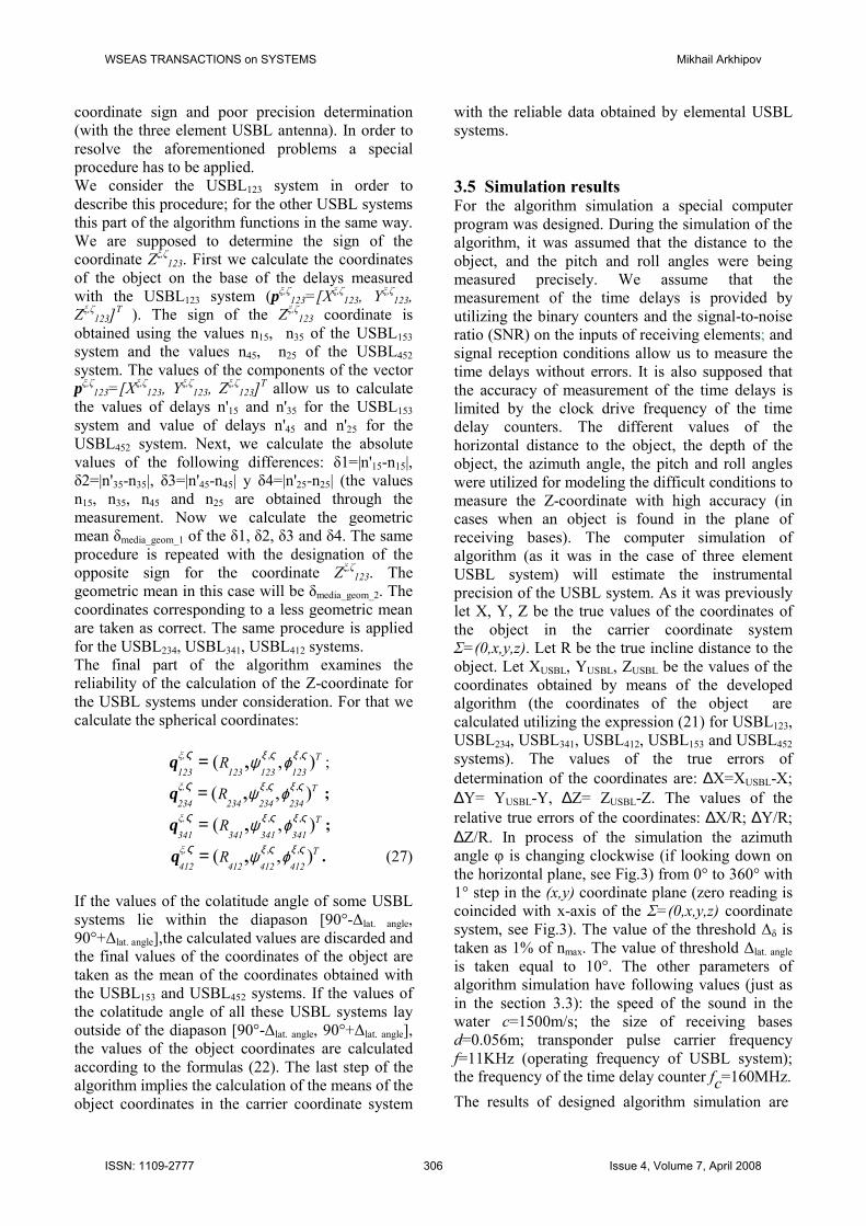
Fig.6. Variation of the relative errors of the object coordinates and modulus of the latitude angle to the transponder (object) relatively the USBL123 plane; R=100m; Z=15 m; ξ=5°; ζ= –6°. five element USBL system. In the considered case, the problem is resolved by means of the different orientations of the basic USBL antennas in the space. This allows at least one elemental USBL antenna which measures the Z-coordinate with high accuracy. As mentioned above the elemental USBL system also has the sign Z-coordinate problem. The possible inclinations of receiving antenna force to include this problem in the designed coordinate determination algorithm. The designed algorithm is presented in the next section. The algorithm has two parts. The first part supports the object coordinate calculation by using the data obtained on USBL412 and USBL153 systems. The second part of the algorithm utilizes the data obtained on USBL123, USBL234, USBL341, USBL412 systems and some results of the first part of the algorithm. 3.4 Algorithm description It is assumed that the measured values are: ξ – pitch angle of receiving antenna; ζ – roll angle of receiving antenna (see Fig.3); n12, n32, n23, n43, n34, n14, n41, n24, n15, n35, n45, n25 - time delays for receiving bases of the corresponding USBL123, USBL234, USBL341, USBL412, USBL153 and USBL452 systems to secure the positive values of measured delays the output signals of each common receiving element of three element USBL system are inverting. The resulting time delays on each base can be expressed as follows: nij=fc(τij+T/2), where fc is the frequency of the time delay counter, τij is the time delay between the receiving elements of
WSEAS TRANSACTIONS on SYSTEMS Mikhail Arkhipov
ISSN: 1109-2777 304 Issue 4, Volume 7, April 2008

n 15,
n 35,
n 45,
n 25
nijmax
nijmin 0 90φ, deg.180 270 360
n25 n15 n45 n35
Fig.7. Time delays n15, n35, n45 and n25 measured in time delay counter pulses; case when the object is located in the plane of the USBL123 (USBL234, USBL341, USBL412) receiving bases. the USBL system (j is the index of the common receiving element), T is the period of the transponder pulse carrier frequency. First the vector pξ,ζ153=[Xξ,ζ153, Yξ,ζ153, Zξ,ζ153]T is calculated. The sign of the Zξ,ζ153 coordinate is defined utilizing time delay values obtained on the USBL452 system (values n45, n25). The behavior of the time delays n15, n35, n45, n25 (n15=n15(φ), n35=n35(φ), etc.) in the case of the non inclined receiving antenna (ξ=0, ζ=0) and when the transponder is located in the plane of elemental horizontal USBL systems is shown in Fig.7. The angle φ changes clockwise from 0° to 360° with 1° step in the (x,y) coordinate plane of the carrier coordinate system (as before, the zero reading is coincided with x-axis of the Σ=(0,x,y,z) coordinate system, see Fig.3). If n45>n25 φ lies in [270°-360°] or [0°-90] range the sign of the Zξ,ζ153 coordinate is negative; if n45≤n25 φ lies in [90°-270°] range the Zξ,ζ153 coordinate has a positive sign. With the obtained values of the vector pξ,ζ153=[Xξ,ζ153, Yξ,ζ153, Zξ,ζ153]T the values of n'45 y n'25 are computed for the USBL452 system. The modules of the differences δ1=|n'45-n45| and δ2=|n'25-n25| are then calculated (values n45 y n25 are obtained through the measurement). If δ1 and δ2 are less than the threshold ∆δ, it is assumed that the sign of the coordinate Zξ,ζ153 is defined correctly, if δ1 and δ2 are greater than the threshold ∆δ, one should consider changing the sign of the coordinate Zξ,ζ153. The same procedure is applied to the USBL452 system vector pξ,ζ452=[Xξ,ζ452, Yξ,ζ452, Zξ,ζ452]T in order to define the sign of the Zξ,ζ452 coordinate.
Coordinate vectors in spherical coordinate system can be expressed as follows: , ,( , ),ξ T
153 153 153 153R ξ ξς ς ςψ ϕ, q = ;
, ,( , ),ξ T452 452 452 452
R ξ ξς ς ςψ ϕ, q = . (24) Furthermore the mean values of the Cartesian coordinates of the object in the carrier coordinate system are calculated. Throughout the calculation of the mean value the angle between the plane of the measuring antenna location and the direction to the object (latitude angle to object) is analyzed. If the values of the corresponding colatitude angles of both systems are found within [90°-∆lat. angle, 90°+∆lat. angle] diapason, the values of the system with greater latitude angles should be kept for further consideration. If the value of the colatitude angle of one of the USBL systems belongs to the diapason [90°-∆lat. angle, 90°+∆lat. angle] and the value of the colatitude angle of the other system lies outside the diapason [90°-∆lat. angle, 90°+∆lat. angle] the value of the first system is not taken into account and the value obtained from another system is utilized. The final step in the coordinate determination is the calculation of the Cartesian coordinates of the object in the coordinate system of the carrier. These calculations for the USBL153 and USBL452 systems are carried out according to the formulas (22). In second stage of the algorithm we calculate the means of the spherical coordinates of the object based on the mean values of the Cartesian coordinates obtained on the first stage:
( ),, TUSBL_153_452 USBL_153_452 USBL_153_452 USBL_153_452
R ψ ϕq = . (25)
Furthermore he inclination angle Ω of the horizontal USBL systems (plane of location of the antennas of the USBL123, USBL234, USBL341, USBL412 systems) is computed using the measurements of pitch and roll angles. The altitude angle Ψ of the object relative to the absolute horizontal plane (horizontal plane of the carrier coordinate system) is calculated as follows:
| |USBL_153_452
90° ψΨ = - . (26)
If Ψ > (Ω + ∆lat. angle) the object coordinates are computed using the values obtained by the horizontal measuring systems (USBL123, USBL234, USBL341, USBL412) applying formulas (22). In case Ψ ≤ (Ω + ∆lat. angle) one faces problems of Z-
WSEAS TRANSACTIONS on SYSTEMS Mikhail Arkhipov
ISSN: 1109-2777 305 Issue 4, Volume 7, April 2008
coordinate sign and poor precision determination (with the three element USBL antenna). In order to resolve the aforementioned problems a special procedure has to be applied. We consider the USBL123 system in order to describe this procedure; for the other USBL systems this part of the algorithm functions in the same way. We are supposed to determine the sign of the coordinate Zξ,ζ123. First we calculate the coordinates of the object on the base of the delays measured with the USBL123 system (pξ,ζ123=[Xξ,ζ123, Yξ,ζ123, Zξ,ζ123]T ). The sign of the Zξ,ζ123 coordinate is obtained using the values n15, n35 of the USBL153 system and the values n45, n25 of the USBL452 system. The values of the components of the vector pξ,ζ123=[Xξ,ζ123, Yξ,ζ123, Zξ,ζ123]T allow us to calculate the values of delays n'15 and n'35 for the USBL153 system and value of delays n'45 and n'25 for the USBL452 system. Next, we calculate the absolute values of the following differences: δ1=|n'15-n15|, δ2=|n'35-n35|, δ3=|n'45-n45| y δ4=|n'25-n25| (the values n15, n35, n45 and n25 are obtained through the measurement. Now we calculate the geometric mean δmedia_geom_1 of the δ1, δ2, δ3 and δ4. The same procedure is repeated with the designation of the opposite sign for the coordinate Zξ,ζ123. The geometric mean in this case will be δmedia_geom_2. The coordinates corresponding to a less geometric mean are taken as correct. The same procedure is applied for the USBL234, USBL341, USBL412 systems. The final part of the algorithm examines the reliability of the calculation of the Z-coordinate for the USBL systems under consideration. For that we calculate the spherical coordinates:
, ,( , ),ξ, T123 123 123 123
R ξ ξς ςς ψ ϕ q = ; , ,( , ),ξ, T
234 234 234 234R ξ ξς ςς ψ ϕ q = ;
, ,( , ),ξ, T341 341 341 341
R ξ ξς ςς ψ ϕ q = ; , ,( , ),ξ, T
412 412 412 412R ξ ξς ςς ψ ϕ q = . (27)
If the values of the colatitude angle of some USBL systems lie within the diapason [90°-∆lat. angle, 90°+∆lat. angle],the calculated values are discarded and the final values of the coordinates of the object are taken as the mean of the coordinates obtained with the USBL153 and USBL452 systems. If the values of the colatitude angle of all these USBL systems lay outside of the diapason [90°-∆lat. angle, 90°+∆lat. angle], the values of the object coordinates are calculated according to the formulas (22). The last step of the algorithm implies the calculation of the means of the object coordinates in the carrier coordinate system
with the reliable data obtained by elemental USBL systems. 3.5 Simulation results For the algorithm simulation a special computer program was designed. During the simulation of the algorithm, it was assumed that the distance to the object, and the pitch and roll angles were being measured precisely. We assume that the measurement of the time delays is provided by utilizing the binary counters and the signal-to-noise ratio (SNR) on the inputs of receiving elements; and signal reception conditions allow us to measure the time delays without errors. It is also supposed that the accuracy of measurement of the time delays is limited by the clock drive frequency of the time delay counters. The different values of the horizontal distance to the object, the depth of the object, the azimuth angle, the pitch and roll angles were utilized for modeling the difficult conditions to measure the Z-coordinate with high accuracy (in cases when an object is found in the plane of receiving bases). The computer simulation of algorithm (as it was in the case of three element USBL system) will estimate the instrumental precision of the USBL system. As it was previously let X, Y, Z be the true values of the coordinates of the object in the carrier coordinate system Σ=(0,x,y,z). Let R be the true incline distance to the object. Let XUSBL, YUSBL, ZUSBL be the values of the coordinates obtained by means of the developed algorithm (the coordinates of the object are calculated utilizing the expression (21) for USBL123, USBL234, USBL341, USBL412, USBL153 and USBL452 systems). The values of the true errors of determination of the coordinates are: ∆X=XUSBL-X; ∆Y= YUSBL-Y, ∆Z= ZUSBL-Z. The values of the relative true errors of the coordinates: ∆X/R; ∆Y/R; ∆Z/R. In process of the simulation the azimuth angle φ is changing clockwise (if looking down on the horizontal plane, see Fig.3) from 0° to 360° with 1° step in the (x,y) coordinate plane (zero reading is coincided with x-axis of the Σ=(0,x,y,z) coordinate system, see Fig.3). The value of the threshold ∆δ is taken as 1% of nmax. The value of threshold ∆lat. angle is taken equal to 10°. The other parameters of algorithm simulation have following values (just as in the section 3.3): the speed of the sound in the water c=1500m/s; the size of receiving bases d=0.056m; transponder pulse carrier frequency f=11KHz (operating frequency of USBL system); the frequency of the time delay counter fc=160MHz. The results of designed algorithm simulation are
WSEAS TRANSACTIONS on SYSTEMS Mikhail Arkhipov
ISSN: 1109-2777 306 Issue 4, Volume 7, April 2008

104 (∆X
/R),
104 (∆
Y/R
), 10
4 (∆
Z/R
), |ψξ,ζ 12
34-9
0°|, d
eg.
20
10
0
-100 90 180 270 360
φ, deg.
• • • • |ψξ,ζ1234-90°|
104(∆Z/R) °°°° 104(∆Y/R)
×××× 104(∆X/R)
Fig.8. Variation of the relative errors of the object coordinates and modulus of the latitude angle to the transponder (object) relatively the USBL1234 plane; R=100m; Z=15 m; ξ=5°; ζ= –6°. shown in Figs.8-11. From Fig.8 (R=100m; Z=15m; ξ=5°; ζ= –6°) it is seen that the relative errors (∆X/R, ∆Y/R, ∆Z/R) of all three coordinates have not exceeded the threshold of 0.1% of inclined distance to the object. Some increase of relative error ∆Y/R can be observed when the modulus of altitude angle |ψξ,ζ1234 -90°| is less than 3° (this corresponds to azimuth angle diapason [270°-360°]). The graphs in Fig.9 illustrate the variation of relative errors of object coordinates for the case when R=100m; Z=40 m; ξ= –20°; ζ=10°. Relative location of
104 (∆X
/R),
104 (∆
Y/R
), 10
4 (∆
Z /R
), |ψξ,ζ 12
34-9
0°|, d
eg.
20
10
0
-10
-200 90 180
φ, deg.270 360
104(∆Z/R)
• • • • |ψξ,ζ1234-90°|
×××× 104(∆X/R)
°°°° 104(∆Y/R)
Fig.9. Variation of the relative errors of the object coordinates and modulus of the latitude angle to the transponder (object) relatively the USBL1234 plane; R=100m; Z=40 m; ξ= –20°; ζ=10°.
measuring system and object (with predetermined spatial orientation of receiving antenna) defines the case of significant inclination of receiving antenna and when the object can be found in the plane of horizontal receiving bases of USBL system. It is seen that the relative errors not exceed the threshold of 0.2% of incline distance in all diapason of changing azimuth angle φ. In wide diapason of values of the azimuth angle φ (from 0° to 120° and from 190° to 360°) the relative coordinate errors are less than 0.05%. Also it is seen that when the modulus of altitude angle |ψξ,ζ1234 -90°| is less than 3° the fluctuations of relative errors are increased (see Fig.9, φ takes on the values from 120° to 190°). The results of calculation of the relative errors for the significant inclination angles of receiving antenna are shown in Fig.10 and Fig.11. In Fig.10 the pitch and roll angle have values: ξ= –30°; ζ= 20°; in the Fig.11 the pitch and roll angles are: ξ= –40°; ζ= –40°. From the present curves we can note that as before the noticeable fluctuations of the relative errors are observed when the values of the altitude angle |ψξ,ζ1234 -90°| are approximately less than 3° (the object is in the plane of the inclined horizontal receiving bases of USBL antenna or close to this plane). With the latitude angle increasing the fluctuations of the relative errors are rapidly decreased (see Fig.10 and Fig.11 for the values of latitude angle more than 10°). The designed algorithm has been examined for various relative locations of the measuring system and object (lower hemisphere was considered, the maximum incline distance was assumed to be
104 (∆X
/R),
104 (∆
Y/R
), 10
4 (∆
Z/R
), |ψξ,ζ 12
34-9
0°|, d
eg.
20
10
0
-10
-200 90 180 270
φ, deg.360
• • • • |ψξ,ζ1234-90°|
×××× 104(∆X/R)
°°°° 104(∆Y/R)
104(∆Z/R)
Fig.10. Variation of the relative errors of the object coordinates and modulus of the latitude angle to the transponder (object) relatively the USBL1234 plane; R=100m; Z=50 m; ξ= –30°; ζ=20.
WSEAS TRANSACTIONS on SYSTEMS Mikhail Arkhipov
ISSN: 1109-2777 307 Issue 4, Volume 7, April 2008

104 (∆X
/R),
104 (∆
Y/R
), 10
4 (∆
Z/R
), |ψξ,ζ 12
34-9
0°|, d
eg.
20
10
0
-10
-200 90 180
φ, deg.270 360
• • • • |ψξ,ζ1234-90°|
×××× 104(∆X/R)
°°°° 104(∆Y/R)
104(∆Z/R)
Fig.11. Variation of the relative errors of the object coordinates and modulus of the latitude angle to the transponder (object) relatively the USBL1234 plane; R=100m; Z=150 m; ξ= –40°; ζ= –40°. 100m). The values of pitch and roll angles ξ and ζ are assumed to be in the range from –40° to +40°. The computer simulation demonstrated the reliable operation of the algorithm for all tested angular antenna positions and verified locations of object. The results of the calculation of the errors of the determination of the coordinates of the object show that the relative true errors of the coordinates have values less than 0.2%. It is also necessary to mention, that in a wide range of distances, depths, pitch and roll angles the values of true relative errors were less than 0.1%. 4 Conclusion The problem of the accuracy enhancement of the USBL systems has been considered. In particular the low Z-coordinate determination accuracy problem for the cases when the object is located in the plane (or close to the plane) of the receiving USBL array has been investigated. The proposed approach of the accuracy enhancement is based on the idea of increasing the number of receiving elements (and hence the number of receiving bases) of the USBL antenna and utilization of the information from this additional receiving bases for object position determination. In particular, the fourth element is added to the horizontal array to form the additional three basic USBL systems and the fifth element is added to obtain two additional three element USBL systems with receiving bases placed in the orthogonal vertical planes. The coordinate determination algorithm was designed for the proposed five elements USBL
system. In process of algorithm designing it was supposed that the receiving antenna is fixed on a carrier and may have inclination defined by the pitch and roll angles. The computer simulation of the designed algorithm was realized. Different angular antenna positions and various object locations have been investigated in process of algorithm simulation. Simulation results showed the reliable operation of the designed algorithm for all tested angular antenna positions and verified locations of object. The presented calculations of errors of the object coordinates determination have demonstrated significant improvement of the Z-coordinate determination accuracy. The calculations of errors in determination of the object coordinates show that the relative true errors of the coordinate determination have values less than 0.2% of the measured distance, so the coordinate determination accuracy of the proposed USBL system may be evaluated as 0.2% of slant distance to the object. References: [1] P.H. Milne, Underwater Acoustic Positioning
System, Gulf Publishing Company, 1983. [2] K. Vickery, Acoustic positioning systems, A
practical overview of current systems. Proceedings of the 1998 Workshop on Autonomous Underwater Vehicles, 1998, p.5-17.
[3] R.J. Urick, Principles of Underwater Sound, 3-rd ed., McGraw-Hill, 1983.
[4] D.R.C. Philip, An Evaluation of USBL and SBL Acoustic Systems and the Optimisation of Methods of Calibration - Part 1, The Hydrographic Journal, No.108, 2003, pp. 18-25.
[5] P. Liu, R. Silva. A new approach to three-dimensional underwater tracking that considers acoustic medium effects. Acoustics, Speech, and Signal Processing, IEEE International Conference on ICASSP, Vol.11, 1986, pp. 2839- 2842.
[6] J.S. Collins, C.J. Randell, Auto-alignment of acoustic transducers in a multipath environment, Communications, Computers and Signal Processing, IEEE Pacific Rim Conference Proceedings, Vol.2, 1993, pp. 714-717.
[7] M. Watson, C. Loggins, Y.T. Ochi, A New High Accuracy Super Short Base Line (SSBL) System, Underwater Technology, Proceedings of 1998 International Symposium, 1998, pp. 210-215.
WSEAS TRANSACTIONS on SYSTEMS Mikhail Arkhipov
ISSN: 1109-2777 308 Issue 4, Volume 7, April 2008

[8] D. Thomson, S. Elson, New generation acoustic positioning systems, Proceedings of Oceans '02 MTS/IEEE, Vol.3, 2002, pp. 1312-1318.
[9] F.V.F. Lima, C.M. Furukawa, Development and Testing of an Acoustic Positioning System - Description and Signal Processing, Ultrasonics Symposium, Proceedings, 2002 IEEE, Vol.1, 2002, pp. 849-852.
[10] P.P.J. Beaujean, A.I. Mohamed, R. Warin, Acoustic Positioning Using a Tetrahedral Ultrashort Baseline Array of an Acoustic Modem Source Transmitting Frequency-hopped Sequences, The Journal of the Acoustical Society of America, Vol.121, No.1, 2007, pp. 144-157.
[11] P.K. Ray, A. Mahajan, Optimal Configuration of receivers in an Ultrasonic 3D Position Estimation System by Using Generic Algorithms. IEEE, Proceedings of the American Control Conference, 2000, Vol.4, pp. 2902-2906.
[12] D.R.C. Philip, An Evaluation of USBL and SBL Acoustic Systems and the Optimisation of Methods of Calibration - Part 2, The Hydrographic Journal, No.109, 2003, pp. 10-20.
[13] I.N. Bronshtein, K.A. Semendyayev, Handbook of Mathematics, Verlag Harri Deutsch, Thun and Frankfurt/Main, 1985.
WSEAS TRANSACTIONS on SYSTEMS Mikhail Arkhipov
ISSN: 1109-2777 309 Issue 4, Volume 7, April 2008