Embed Size (px)
Citation preview

EE595
Part VIIVHDL Synthesis Techniques
and Recommendations
EE 595 EDA / ASIC Design Lab

IntroductionSynthesis is the translation process from an abstract description of a hardware device into an optimized technology specific gate level implementationMay be done
Manually via schematic entryAutomatically via EDA tools that use a hardware description language (HDL) as an input medium to generate constraint driven gate configurations.
EE 595 EDA / ASIC Design Lab

Pre-Synthesis StepsFunctional Specification of the designDesign Entry
HDL Coding in VHDL/Verilog RTL
Graphical Entry Tools
Summit Design (Visual XOR)SpeedChart (Speed Electronics)Simulation Graphical Environment (Synopsys SGE)Design Source (Synopsys)Design Manager (Mentor)View Draw (Viewlogic)Escalade (Design Book)
EE 595 EDA / ASIC Design Lab
HDL Based Design Flow

HDL Based Design FlowPre-Synthesis Steps (cont.)
RTL/Behavioral or Functional Simulation of the HDLModel Technologies (MTI)Quicksim (Mentor)Synopsys VHDL System Simulator (VSS)Vantage (ViewLogic)Leapfrog (Cadence)Verilog XL(Cadence)Chronologic (Viewlogic)
SYNTHESIS:Logic synthesis is the process of translating and optimizing a high-level design description to gates from a technolgy library
EE 595 EDA / ASIC Design Lab

Synthesis DefinitionTranslation: Conversion of RTL into an unoptimizedgate-level description.
Logic Optimization: Transition from a suboptimal generic logic implementationto a closer-to-optimal implementation in terms of area and speed
Technology Mapping:Transition from an optimized generic netlist to cells from ASIC vendor’s library
EE 595 EDA / ASIC Design Lab

Synthesis
EE 595 EDA / ASIC Design Lab
High-Level DesignCapture
Synthesis
Gates
Synthesis
ConstraintsMet?

Post SynthesisASIC Synthesis
Design Compiler (Synopsys)Bool-Dozer (IBM)Synergy (Cadence)Autologic (Mentor)
FPGA Synthesis FPGA Compiler FPGA Compiler (Synopsys)Logic Explorer (Galileo, Exempler)
Timing AnalysisStaticDynamicHybrit
EE 595 EDA / ASIC Design Lab

Post SynthesisTest Insertion, Pad Synthesis & ATPG
Synopsys Test CompilerSunrise (ViewLogic)Mentor
Post Synthesis, gate-level Simulation Model TechnologiesVerilog XL, (Cadence)
FloorplanningPlace and R0uteBack AnnotationIn Place optimization (Design Compiler)Gate Level Simulation (MTI)
EE 595 EDA / ASIC Design Lab

Post - SynthesisTransistor Level Simulation, Pad Synthesis & ATPG
TimeMill (EPIC)PowerMill (EPIC))
Engineering Change OrderTapeoutTest Vector Generation
EE 595 EDA / ASIC Design Lab

DisclaimerThough VHDL Is a Key Element of a Synthesis Activity It Is Only Part of the Solution
Target Library Design RulesHardware Timing GoalsHardware Area Goals Environmental Goals
Digital Designer Must Also Master the SynopsysProprietary GUI and Command Language Features in Order to Ensure That the Synthesized Hardware Will Best Satisfy All of Its Intended Real-World Design Constraints and Goals.
EE 595 EDA / ASIC Design Lab

Forces Driving Synthesis Algorithm
EE 595 EDA / ASIC Design Lab
Design Constraints
Target TechnologyEnvironmental Attributes
HDL Coding Style

Hardware Description Languages and Synthesis
Hardware Description Language (HDL) Used to Model Targeted Device Is Technology Independent
During Synthesis Appropriates Cells Are Selected From the User Specified Technology Library
HDL Coding Style Is a Very Important Driving Force for the Automated Synthesis Algorithms and Will Play Role in the Final Hardware Configuration That Is Build.
EE 595 EDA / ASIC Design Lab

Synthesized Combinational Logic: Possible Alternatives
EE 595 EDA / ASIC Design Lab
AB
C D
AB
C D
During the synthesis NAND gates maybe selected because of:
• Gate availability's in targetedTechnology
• Area Minimization requirements

Synthesized Combinational Logic: Possible Alternatives (cont’d)
EE 595 EDA / ASIC Design Lab
AB
C
AB
C D
D
Additional Buffers may be included inorder to satisfy an output drive specification

Key Synthesis FactIn General, Synthesis Does Not Support the After Clause in a Signal Assignment
In the Baseline Synthesis Domain Signal Updates Should Be Scheduled to Occur at the Next Delta Time Unit in the SimulationDomain
Note: Synopsys Behavioral Compiler Product Supports the After Clause
EE 595 EDA / ASIC Design Lab
C <= A and B after 10 Ns -- Not Supported by Baseline-- Synthesis Tool Suite
C <= A and B after 10 Ns -- Not Supported by Baseline-- Synthesis Tool Suite
C <= A and B -- Supported by SynthesisC <= A and B -- Supported by Synthesis

Static Sensitivity RuleIf the synthesized process has a static sensitivity list, then every read signal must be a member of this list. Otherwise the synthesis tool will create a hardware configuration that concurs with this requirement even though the original process does not.
Might result in possible VHDL simulation, Synthesis Mismatches.
EE 595 EDA / ASIC Design Lab

Static Sensitivity Rule
EE 595 EDA / ASIC Design Lab
process (A, B)begin
D <= (A AND B) OR C;end process;
process (A, B)begin
D <= (A AND B) OR C;end process;
process (A, B, C)begin
D <= (A AND B) OR C;end process;
process (A, B, C)begin
D <= (A AND B) OR C;end process;
Original VHDL Model
Synthesis view and Re-interpretationof original VHDL code.
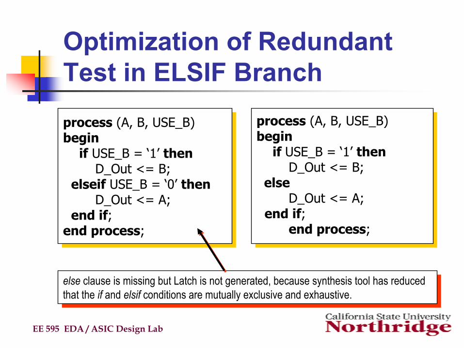
Optimization of Redundant Test in ELSIF Branch
EE 595 EDA / ASIC Design Lab
process (A, B, USE_B)begin
if USE_B = ‘1’ thenD_Out <= B;
elseif USE_B = ‘0’ thenD_Out <= A;
end if;end process;
process (A, B, USE_B)begin
if USE_B = ‘1’ thenD_Out <= B;
elseif USE_B = ‘0’ thenD_Out <= A;
end if;end process;
process (A, B, USE_B)begin
if USE_B = ‘1’ thenD_Out <= B;
elseD_Out <= A;
end if;end process;
process (A, B, USE_B)begin
if USE_B = ‘1’ thenD_Out <= B;
elseD_Out <= A;
end if;end process;
else clause is missing but Latch is not generated, because synthesis tool has reduced that the if and elsif conditions are mutually exclusive and exhaustive.
else clause is missing but Latch is not generated, because synthesis tool has reduced that the if and elsif conditions are mutually exclusive and exhaustive.

VHDL => LATCHLatches are inferred during Synthesis. Whenever the Following Conditions Occur:
Conditional Expression Are Not Completely SpecifiedElse Clause Is Omitted
Objects Conditionally Assigned in an If Statement are not assigned a value before entering this if statementThe VHDL attribute ‘Event is not present in the conditional expression
EE 595 EDA / ASIC Design Lab

If Statement => LATCH
EE 595 EDA / ASIC Design Lab
process (ENABLE, DATA)begin Data Q
if ENABLE = ‘1’ thenQ <= DATA; LATCHend if; Enable
end process;

Reasoning Behind Latch inference
A latch is inferred during synthesis so that the derived hardware will agree with the VHDL fact that signals and process declared variables maintain their respected value until they are assigned new ones.
EE 595 EDA / ASIC Design Lab

Synthesis Rules Regarding ‘Z’‘Z’ cannot occur in an expression
the following line will be flagged as an error during the synthesis elaboration phase
DATAOUT <= ‘Z’ AND DATA_IN;
Though accepted by synthesis comparison to ‘Z’ are always interpreted as being false
this assumption will lead to a simulation / synthesis if DATA_IN = ‘Z’ then
is synthesized the same asif false then
EE 595 EDA / ASIC Design Lab

Importance of Good Coding Style: Efficient Synthesized hardwareBecause the WHEN conditions of a VHDL case statement aremutually exclusive and exhaustive synthesis rules can efficiently derive a single MUX equivalent circuit.
EE 595 EDA / ASIC Design Lab
process( SEL, A, B, C, D)begin
case SEL iswhen “00”=>D_Out <=A;when “01”=>D_Out <=B;when “10”=>D_Out <=C;when “11”=>D_Out <=D;
end caseend process
process( SEL, A, B, C, D)begin
case SEL iswhen “00”=>D_Out <=A;when “01”=>D_Out <=B;when “10”=>D_Out <=C;when “11”=>D_Out <=D;
end caseend process“00”
“01”“10”
“11”
A
C
D
B
SEL

Observation Regarding:Observation Regarding:FOR Statement => Combinational LogicFOR Statement => Combinational Logic
Variable Used Because Inertial Signal Updates Will Neither Simulate nor Synthesize CorrectlyIn Essence for Loop Is Unraveled During Synthesis
Transport Delay Models Are Not Supported by Synthesis
Assignment to Result Before Entering for Loop Is Required Because Synthesis Requires That Variables Be Written to Before They Are ReadOtherwise a Warning Message Will Be Generated During Elaboration
Might Then Synthesize Into a Circuit With Feedback Loop
EE 595 EDA / ASIC Design Lab

State EncodingBy default synthesis implements a state encoding that reflects the binary presentation of the ‘POS value of the machines state enumeration type.
for Example type STATE_TYPE is (SO, S1, S2, S3);
Since STATE_TYPE’POS(S0) = 0 , state SO is encoded into “00”Analogously S1, S2, S3 are encoded into “01” “10” and
“11” respectively.
EE 595 EDA / ASIC Design Lab