Embed Size (px)
Citation preview

Ultra-low Power Practices, Watchdog timer, Real-Time Clock (RTC),
Timer_A
LECTURE - 6
11
Timer_A
Atul Lele, Ramakrishna Reddy K,
MSP430 Design,
Texas Instruments India Pvt Ltd.
2/16/2012
Outline of today’s session
• What have we learnt in the last session
• Agenda for this session
– Ultra-low Power Practices
– Lab2B: Applying Ultra Low Power (ULP) Principles
– Introduction to MSP430 Peripherals - I
22
– Introduction to MSP430 Peripherals - I
• Watchdog timer (WDT)
• Real Time Clock (RTC)
• Timer_A
– Lab3: Using the Timer_A module
• Wrap-Up
• Q&A2/16/2012

What have we learnt in the last session
332/16/2012

What have we learnt in the last session
• Using Code Composer Studio (CCS) for
programming MSP430
• Pin-multiplexing in MSP430
• Low Power Modes (LPM) in MSP430
4

Ultra-low Power Practices
55

Ultra-low Power Activity Profile
6
Always-on
On demand

Principles For ULP Applications• Maximize the time in LPM3
• Use interrupts to control program flow
• Replace software with peripherals
• Power manage external devices
• Configure unused pins properly
• Efficient code makes a difference
• Even wall powered devices can be “greener”
• Every unnecessary instruction executed is a portion of the battery
7
• Every unnecessary instruction executed is a portion of the battery wasted that will never return
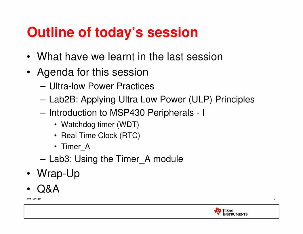
Performance on Demand
Interrupt
8
MCLK
Immediate-stable clock start for quick reaction to events
Note: MCLK is provided by the Digitally Controlled Oscillator (DCO)

Low Power Mode Clock Control
OffAll
Clocks Off0.1µA
CPU OffDCO on
ACLK on45µA
LPM0
ActiveDCO on
ACLK on165µA
<1-6µs
<6µs
LPM4
9
Stand-byDCO offACLK on
1.0µA
LPM3• RTC function• LCD driver• RAM/SFR retained
LPM0 <1-6µs
Specific values vary
by device
LPM4• RAM/SFR retained
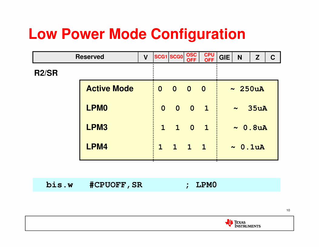
Low Power Mode Configuration
Active Mode 0 0 0 0 ~ 250uA
LPM0 0 0 0 1 ~ 35uA
LPM3 1 1 0 1 ~ 0.8uA
R2/SR
Reserved CSCG1 SCG0 ZNGIECPUOFF
OSCOFFV
10
LPM3 1 1 0 1 ~ 0.8uA
LPM4 1 1 1 1 ~ 0.1uA
bis.w #CPUOFF,SR ; LPM0 bis.w #CPUOFF,SR ; LPM0
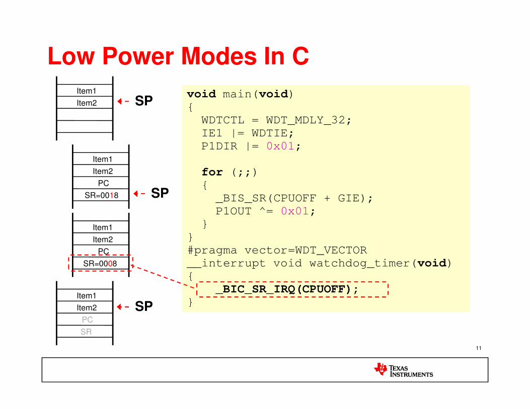
Low Power Modes In C
Item1
Item2
PC
SR=0018
Item1
Item2void main(void)
WDTCTL = WDT_MDLY_32;
IE1 |= WDTIE;
P1DIR |= 0x01;
for (;;)
_BIS_SR(CPUOFF + GIE);
void main(void)
WDTCTL = WDT_MDLY_32;
IE1 |= WDTIE;
P1DIR |= 0x01;
for (;;)
_BIS_SR(CPUOFF + GIE);SP
SP
11
Item1
Item2
PC
SR
Item1
Item2
PC
SR=0008
P1OUT ^= 0x01;
#pragma vector=WDT_VECTOR
__interrupt void watchdog_timer(void)
_BIC_SR_IRQ(CPUOFF);
P1OUT ^= 0x01;
#pragma vector=WDT_VECTOR
__interrupt void watchdog_timer(void)
_BIC_SR_IRQ(CPUOFF); SP

ORG 0F000h RESET mov.w #300h,SP
mov.w #WDT_MDLY_32,&WDTCTL
bis.b #WDTIE,&IE1 bis.b #01h,&P1DIR
Mainloop bis.w #CPUOFF+GIE,SR xor.b #01h,&P1OUT jmp Mainloop
ORG 0F000h RESET mov.w #300h,SP
mov.w #WDT_MDLY_32,&WDTCTL
bis.b #WDTIE,&IE1 bis.b #01h,&P1DIR
Mainloop bis.w #CPUOFF+GIE,SR xor.b #01h,&P1OUT jmp Mainloop
Item1
Item2
PC
SR=0018 SP
SPItem1
Item2
Low Power Modes In Assembly
12
WDT_ISR bic.w #CPUOFF,0(SP)reti
ORG 0FFFEh DW RESET ORG 0FFF4h DW WDT_ISR
WDT_ISR bic.w #CPUOFF,0(SP)reti
ORG 0FFFEh DW RESET ORG 0FFF4h DW WDT_ISR
SPItem1
Item2
PC
SR
Item1
Item2
PC
SR=0008

ULP Operation Best Practices
• Power drawn increases with…– Vcc
– CPU clock speed (MCLK)
– Temperature
• Slowing MCLK reduces instantaneous power, but usually increases active duty cycle
1313
usually increases active duty cycle– Power savings can be nullified
– The ULP ‘sweet spot’ that maximizes performance for the minimum current consumption per MIPS: 8 MHz MCLK
• Full operating range (down to 1.8V)

Terminate Unused Pins
• Digital input pins subject to shoot-through current
– Input voltages between VIL and VIH cause shoot-through if input is allowed to “float” (left unconnected)
• Port I/Os should
– Driven as outputs
1414
– Be driven at Vcc/ground by an external device
– Have a pull-up/down resistor

Terminate Unused Pins
1515
• When P- and N- channels are on simultaneously, result is “shoot-through current.”

Short-Circuit Power (from Lecture-1)
Vdd
Vin Ipeak
Vin
Voutisc
1616
CL
Ipeak
isc
tsc
Psc = tscVddIpeak f = CscV2
dd f
Source : Digital Integrated Circuits, Jan Rabaey et al.
2/16/2012

Move Software Functions to Peripherals
MCUP1.2
// Endless Loop
for (;;)
// Endless Loop
for (;;)
// Setup output unit
CCTL1 = OUTMOD0_1;
_BIS_SR(CPUOFF);
// Setup output unit
CCTL1 = OUTMOD0_1;
_BIS_SR(CPUOFF);
17
100% CPU Load
P1OUT |= 0x04; // Set
delay1();
P1OUT &= ~0x04; // Reset
delay2();
P1OUT |= 0x04; // Set
delay1();
P1OUT &= ~0x04; // Reset
delay2();
_BIS_SR(CPUOFF);_BIS_SR(CPUOFF);
Zero CPU Load
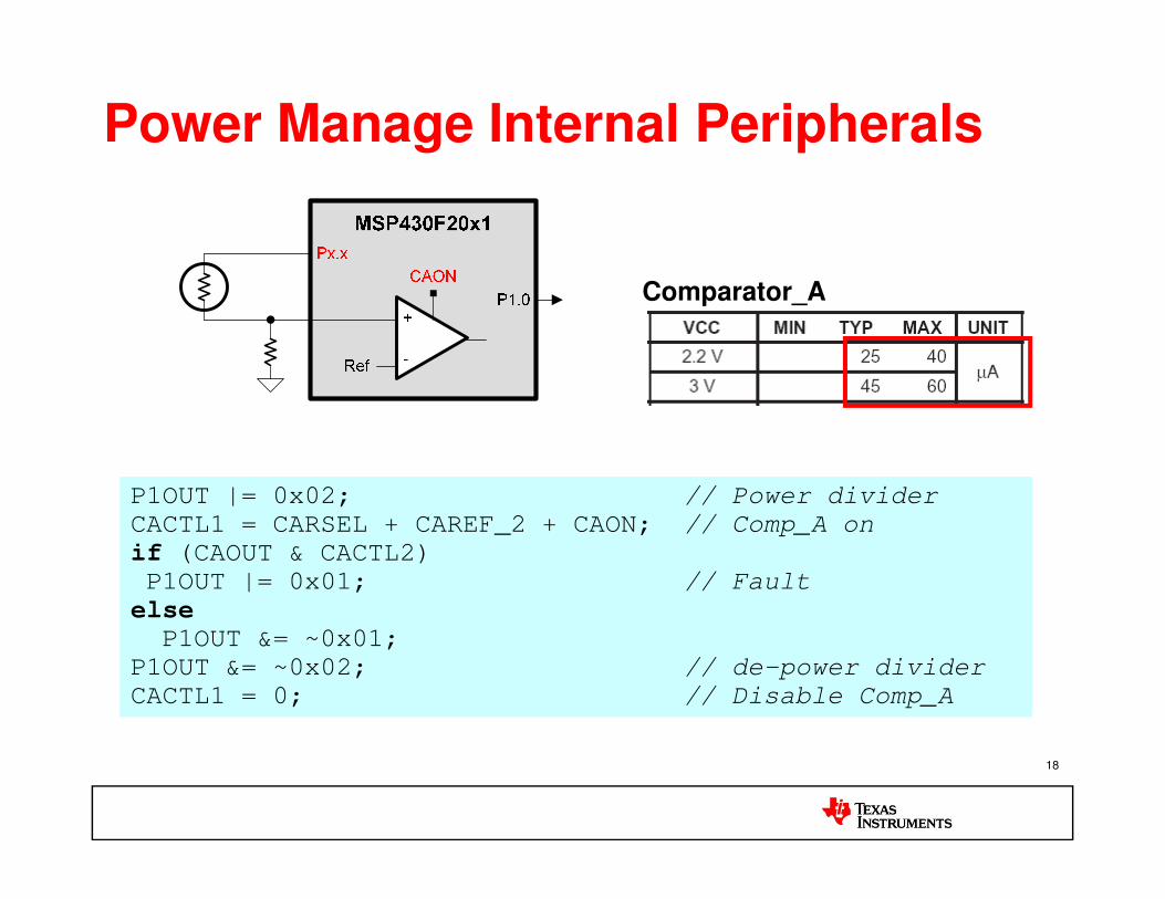
Power Manage Internal Peripherals
Comparator_A
18
P1OUT |= 0x02; // Power divider
CACTL1 = CARSEL + CAREF_2 + CAON; // Comp_A on
if (CAOUT & CACTL2)
P1OUT |= 0x01; // Fault
elseP1OUT &= ~0x01;
P1OUT &= ~0x02; // de-power divider
CACTL1 = 0; // Disable Comp_A
P1OUT |= 0x02; // Power divider
CACTL1 = CARSEL + CAREF_2 + CAON; // Comp_A on
if (CAOUT & CACTL2)
P1OUT |= 0x01; // Fault
elseP1OUT &= ~0x01;
P1OUT &= ~0x02; // de-power divider
CACTL1 = 0; // Disable Comp_A

Lab 2BApplying Ultra Low Power (ULP)
1919
Applying Ultra Low Power (ULP) Principles

Lab 2B Goals
• Create a new CCS project titled LAB2B (same
as LAB1)
Lab2A: Using shutdown mode (LPM4) to reduce
power consumption
Use source code lab2_interrupt.c
20
Use source code lab2_interrupt.c
Configure switch S1 (P1.0) to accept an interrupt
Enable P1IE.0
Put device in LPM4 with global interrupt enabled
Toggle LED4 (P5.1) inside Port ISR
Measure power when JP3 (near LED4) is open
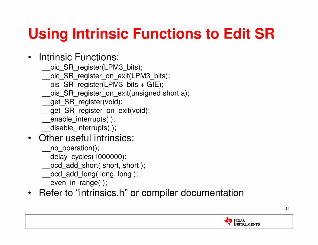
Using Intrinsic Functions to Edit SR
• Intrinsic Functions: __bic_SR_register(LPM3_bits);__bic_SR_register_on_exit(LPM3_bits);__bis_SR_register(LPM3_bits + GIE);__bis_SR_register_on_exit(unsigned short a);__get_SR_register(void); __get_SR_register_on_exit(void);__enable_interrupts( );
2121
__enable_interrupts( );__disable_interrupts( );
• Other useful intrinsics:__no_operation();__delay_cycles(1000000);__bcd_add_short( short, short ); __bcd_add_long( long, long );__even_in_range( );
• Refer to “intrinsics.h” or compiler documentation

Complete the Source Code
Setup P1.0 for an interrupt on
a HI/LOW transition
Enter LPM4 with interrupts
enabled
22
Toggle P5.1
Source file : lab2_interrupt.c

Complete the Source Code
Setup P1.0 for an interrupt on
a HI/LOW transition
Enter LPM4 with interrupts
enabled
23
Source file : lab2_interrupt_solution.c
Toggle P5.1

Build & Debug a CCS Project
2424
Click the “BUG” to build the
code & launch the debugger
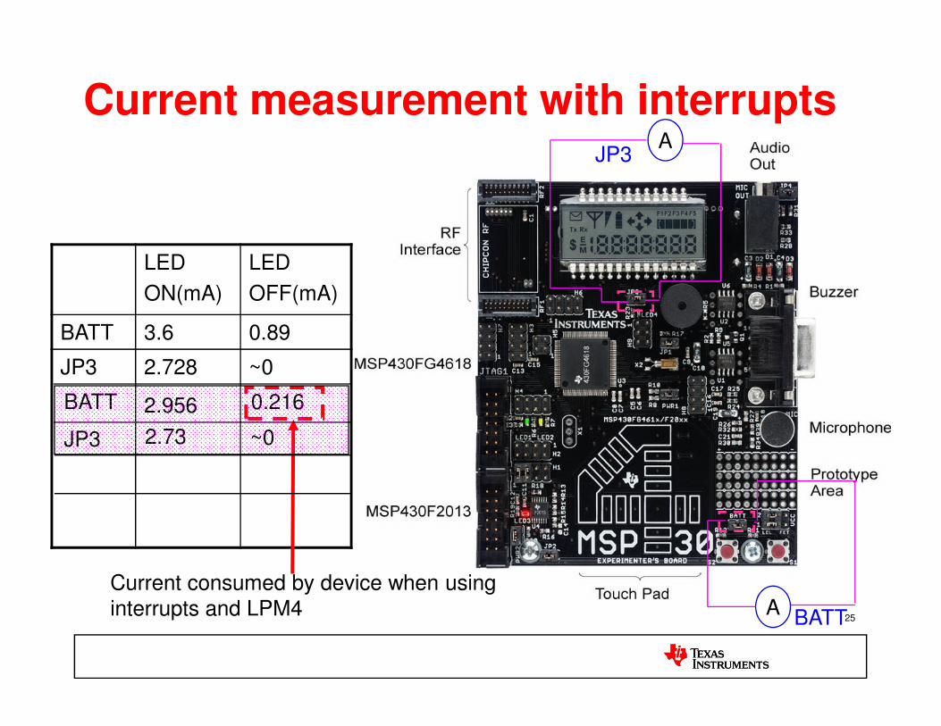
Current measurement with interruptsA
JP3
LED
ON(mA)
LED
OFF(mA)
BATT 3.6 0.89
JP3 2.728 ~0
25A BATT
JP3 2.728 ~0
Current consumed by device when using interrupts and LPM4
BATT 2.956 0.216
JP3 2.73 ~0

Terminating the unused ports to proper values
26
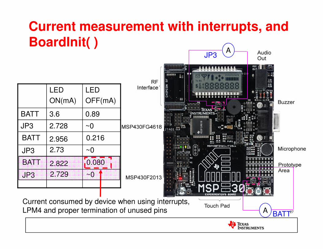
Current measurement with interrupts, and BoardInit( )
AJP3
LED
ON(mA)
LED
OFF(mA)
BATT 3.6 0.89
JP3 2.728 ~0
27A BATT
JP3 2.728 ~0
Current consumed by device when using interrupts, LPM4 and proper termination of unused pins
BATT 2.956 0.216
JP3 2.73 ~0
BATT 2.822 0.080
JP3 2.729 ~0

Lab 2 Check List
Learn about GPIOs and interrupts
Use active mode and poll interrupt flag to check for switch interrupt
Use interrupt driven mode to check for switch interrupt
Applied ULP Principles to understand the difference between using Interrupt Driven & Flag Polling methods
Compare the measured power numbers for active and shutdown modes
28
modes
15 mins

Introduction to MSP430 Peripherals - I
2929

555 Timer in Astable mode
5kΩ
Control
R
__
Vref
Q2
Vcc
RB
RA
4
8
7
6
5 2 __
3Vcc
30
5kΩ
5kΩ
ControlFlip-FlopS Q
__
Q1C
0.01μF
32
1 __3
Vcc
Power
Amplifier

555 Timer Astable mode waveforms
1 __3
Vcc
2 __
3Vcc
V
VC
31
0
Vcc
Output

Introduction
• Timers: Essential to almost any embedded application– Generate fixed-period events
– Periodic wakeup
– Count edges
– Replacing delay loops with timer calls allows CPU to sleep, consuming much less power
• Five types of MSP430 timer modules
32
• Five types of MSP430 timer modules
– Basic timer
– RTC Module
– Watchdog Timer (WDT)
– Timer A/B
• Different tasks/ clock sources call for different timers.

Watchdog Timer (WDT)
33332/16/2012

WDT
• Software watchdogor re-configurable asInterval timer
• Four software selectable intervals
• Any access to
34
• Any access to WDTCTL must include 05A00h password
• Module defaults to active watchdog on power-up

• Software watchdogor re-configurable asInterval timer
• Four software selectable intervals
• Any access to
WDT+
35
• Any access to WDTCTL must include 05A00h password
• Module defaults to active watchdog on power-up
• Clock fail-safe feature in WDT+
Fail-safe logic
MCLK
Note: In 4xx family, MSP430x42x,MSP430FE42x,MSP430FG461x, andMSP430F47x devices only

Watchdog timer control registers
36

Watchdog timer control register (1)
37

Watchdog timer control register (2)
38
Say for SMCLK = 1MHzPeriod of 1 clock cycle = 1us
Maximum interval = 32768us ≈ 32msWDT_MDLY_32 in header file

IE1
39

IFG1
40

Real-time Clock (RTC)
41412/16/2012

Real time clock (RTC)
• 32-bit counter mode with
selectable clock sources
• Calendar and clock
mode
• Automatic counting of
seconds, minutes,
42
seconds, minutes,
hours, day of week, day
of month, month and
year in calendar mode
• Interrupt capability
• Selectable BCD format
Note: Most RTC module registers have no initial condition. These registers must be configured by user software before use
Demo : RTC running on the FG461x board

Timer_A module
43432/16/2012

Timer_A Module: Overview
• The most versatile
• Async 16-bit timer/counter
• Four input clocks, including externally-sourced
• Selectable count mode
• Extensive interrupt capability
• Up to three capture/compare
44
• Up to three capture/compare registers (CCR) generate events when value reached
• “Capture” or “Compare” mode
• Output not only interrupts, but also “output signals”
• Extensive connections to other modules

Timer_A: Capture Mode• Measure time before a signal event
occurs
• Why not just use a CPU interrupt and have CPU fetch timer value?
– Extra cycles expire
– Dependent on interrupts being enabled
• Input signal from:– External pin
45
– External pin
– Internal signal (i.e., Comp_A)
– Vcc/GND
• Edge direction – programmable
• Applications:– Analog signal rising to Comp_A threshold
– Slope ADC
– Frequency measurement
– Vcc threshold detect (via voltage divider)

Timer_A: Compare Mode
• Cause an event after a defined period (exact opposite of capture mode)
• What kind of event?– CPU interrupt
– Modules tied internally to timer output (DMA, start ADC/DAC conversion)
– External components
• Applications:
46
• Applications:– PWM generation
– RTC
– Timer_A UART

Timer_A: Count Modes
• Determines pattern of counter direction– What will it do when it rolls over?
– Does it always count up? Maybe down?
– What is the maximum value?
• The modes:– Continuous: Up to FFFF, rolls over to 0000, back up to FFFF, etc.
– Up: Up to value specified by CCR0, rolls over to 0000, back up to CCR0 value, etc.
47
– Up: Up to value specified by CCR0, rolls over to 0000, back up to CCR0 value, etc.
– Up/down: Up to value specified by CCR0, count down to 0000, back up to CCR0
value, etc.
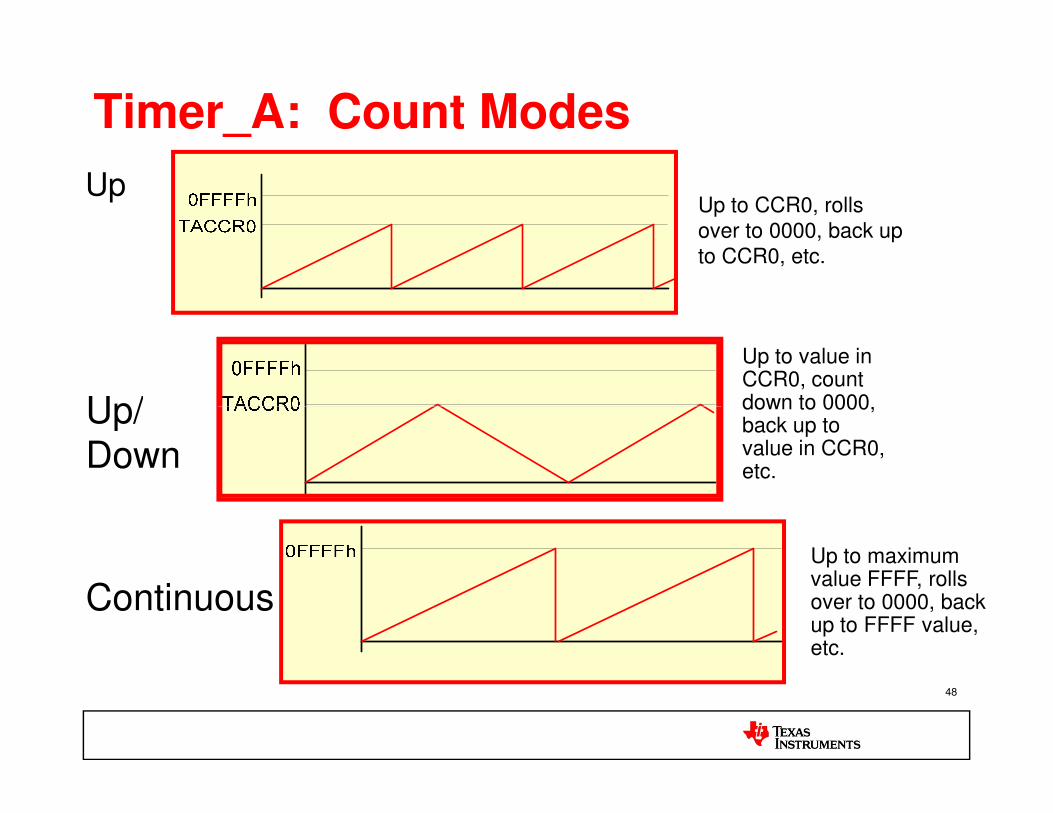
Timer_A: Count Modes
UpUp to CCR0, rolls
over to 0000, back up
to CCR0, etc.
Up/
Up to value in CCR0, count down to 0000,
48
Continuous
Up to maximum value FFFF, rolls over to 0000, back up to FFFF value, etc.
Up/
Down
down to 0000, back up to value in CCR0, etc.
Timer_A: CCR Output Mode
• Each CCR generates an output signal, available externally
• This is a separate and different type of output compared to interrupts
• Operate continuously while CPU sleeps
• Output modes determine how the timer pattern translates to output signal
49
to output signal
• Note that CCR0 plays a role in CCR1-2 output signals
• For different combinations of count modes, output modes, and CCR values, a multitude of outputs and behaviors possible
• Useful for HW PWM generation with no SW intervention

Timer_A: Count Modes
50

Example waveform - 1
CLK
Counter
Compare
00h 01h 11h 12h 7Fh 80h 00h 01h 11h 12h
51
Compare output
P1.1/TA1
TACCR0 = 0x80h Timer in Set/Reset mode
TACCR1 = 0x12h
Set CCR0 IFG
Set TAIFG
Set CCR1 IFG
CLK
Counter
Compare
00h 01h 11h 12h 7Fh 80h 00h 01h 11h 12h
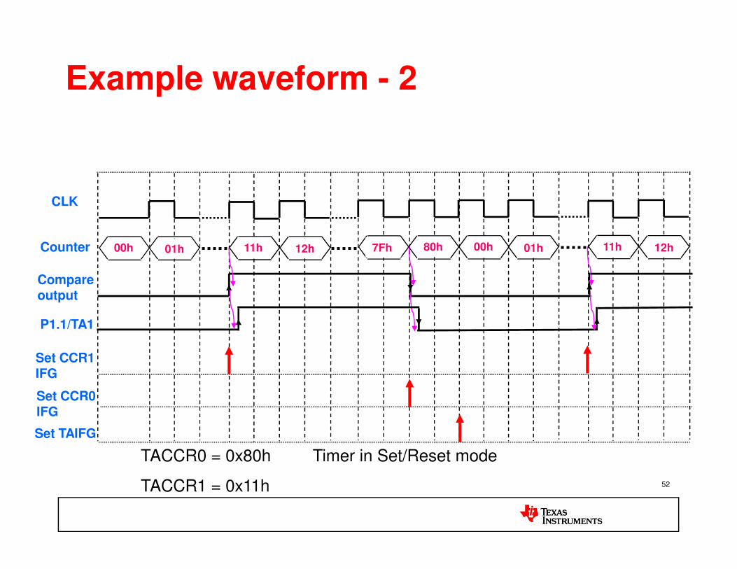
Example waveform - 2
52
Compare output
P1.1/TA1
Set CCR0 IFG
Set TAIFG
Set CCR1 IFG
TACCR0 = 0x80h Timer in Set/Reset mode
TACCR1 = 0x11h

Computing the Timer Interval
• Consider a use case where the timer expiry needs
to be set to 500ms
• Available Clock = F = 32768 Hz (external crystal)
• 1 timer count = 1/32768 = 30.517µs
• Required interval = t (secs) = 500 * 10-3
53
• Required interval = t (secs) = 500 * 10-3
• To generate an interrupt every ‘t’ seconds; the
count to be loaded is given by
TACCR0 = t * F = 16384 counts• Note: The number of timer counts in the period is TACCR0+1. Hence always
load one less than the calculated value to get an accurately timed interrupt

Interrupt Sources and Flags
TACCR0 CCIFG TIMERA0_VECTOR
Source Interrupt Vector
TACCR1 CCIFG
Pri
ori
ty
High
54
TACCR2 CCIFG
TAIFG
TIMERA1_VECTORTAIV
Pri
ori
ty
Low

Interrupt Vector Generator TAIV
0
015
0000000000
Source TAIV ContentsNo interrupt pending 0TACCR1 CCIFG 02hTACCR2 CCIFG 04hReserved 06hReserved 08h
0 x x x x
55
• Shared interrupt vector for CC1/2 IFGs / overflow
• Fast decoding reduces code size / CPU load
• In assembly, add TAIV to PC!
Reserved 08hTAIFG 0AhReserved 0ChReserved 0Eh

Lab3Using the Timer_A Module
5656
Using the Timer_A Module

Lab 3 Goals
• Create a new CCS project titled LAB3
• Attach the source code lab3_timer.c to the project
• Fill in the blanks at the indicated locations
• To complete the lab: Load the register TACCR0 with the appropriate value to
57
Load the register TACCR0 with the appropriate value to generate a 1 second interrupt (see slide 62)
Configure the timer to be sourced from ACLK (refer F4xx User’s Guide)
Set the Timer to UP mode (Refer F4xx User’s Guide)
Set the device to LPM3 while waiting for the timer interrupt
Monitor LED4 (P5.1) to observe 1 second interrupts

Timer Chapter: TACTL Register
58
Use ACLK
Use UP mode

Create a CCS Project
• File > New > CCS Project
• Project Name: LAB3
• Project Type: MSP430
• Additional Project Settings: <None>
• …
5959

Add a File to the CCS Project
• Right click project and “Add Files…”• Navigate to
Desktop\MSP430Training\Labs\Lab3• And select lab3_timer.c
6060

Complete the Source Code
61
Setup timer count, ACLKand UP mode
Enter LPM3 with interrupts enabled
Toggle P5.1
Source: lab3_timer.c

Complete Source Code
62
Setup timer count, ACLKand UP mode
Enter LPM3 with interrupts enabled
Toggle P5.1
Source: lab3_timer_solution.c
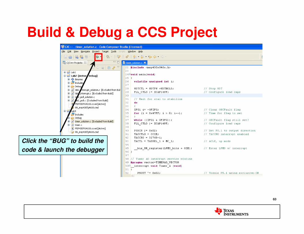
Build & Debug a CCS Project
6363
Click the “BUG” to build the
code & launch the debugger

Lab 3 Check List
Learn about the timer and various modes
Calculate the timer counts needed for a 1 sec interrupt
Use the Timer CCR0 interrupt vector
Toggle the LED every one second in the Timer ISR
64
15 mins

Wrap-Up
65652/16/2012
Wrap-Up
• Ultra-Low Power (ULP) best practices
• Watchdog timer
• Real-Time Clock (RTC)
• Timer_A
66662/16/2012
References
• “Train the Trainer”, courseware prepared by Priya Thanigai, Ramakrishna Reddy K, Texas Instruments, February 2011
• “MSP430 Microcontroller Basics”, John H.Davies, Newnes, 2010
• “MSP430 Teaching ROM”, Pedro Dinis Gaspar, Antnio
6767
• “MSP430 Teaching ROM”, Pedro Dinis Gaspar, Antnio Esprito Santo, Bruno Ribeiro and Humberto Santos University of Beira Interior, Electromechanical Engineering Department, Portugal, 2009
• “The 8051 Microcontroller and Embedded Systems Using Assembly and C”, Muhammad Ali Mazidi, Janice Gillispie Mazidi, Rolin D.McKinlay, Pearson
2/16/2012

68682/16/2012


![Vortrag zur Seminarphase der PG „Solar Doorplate“ MSP430 ... · MSP430 – Wichtigste Grundlagen von David Tondorf. 2 ... MSP430 microcontroller basics. Oxford: Newnes [4] MSP430](https://img.dokumen.tips/doc/110x75/5b6f6a9b7f8b9af12d8c481e/vortrag-zur-seminarphase-der-pg-solar-doorplate-msp430-msp430-.jpg)


![[MSP430] GPIO](https://img.dokumen.tips/doc/110x75/55cf9df0550346d033aff200/msp430-gpio.jpg)