Embed Size (px)
Citation preview
8/3/2019 Lecture 17 the Toroidal Inductor
http://slidepdf.com/reader/full/lecture-17-the-toroidal-inductor 1/15
17-1
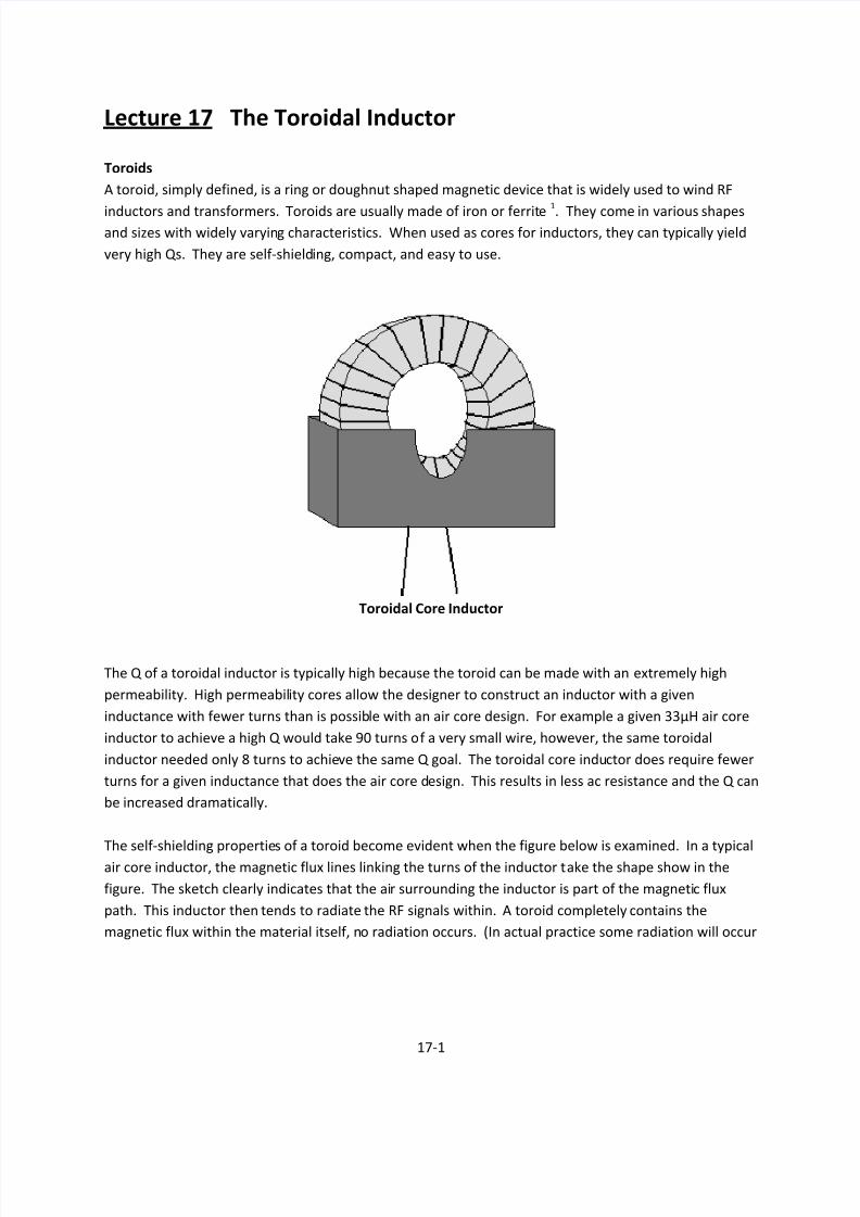
Lecture 17 The Toroidal Inductor
Toroids
A toroid, simply defined, is a ring or doughnut shaped magnetic device that is widely used to wind RF
inductors and transformers. Toroids are usually made of iron or ferrite1
. They come in various shapesand sizes with widely varying characteristics. When used as cores for inductors, they can typically yield
very high Qs. They are self-shielding, compact, and easy to use.
Toroidal Core Inductor
The Q of a toroidal inductor is typically high because the toroid can be made with an extremely high
permeability. High permeability cores allow the designer to construct an inductor with a given
inductance with fewer turns than is possible with an air core design. For example a given 33μH air core
inductor to achieve a high Q would take 90 turns of a very small wire, however, the same toroidal
inductor needed only 8 turns to achieve the same Q goal. The toroidal core inductor does require fewer
turns for a given inductance that does the air core design. This results in less ac resistance and the Q can
be increased dramatically.
The self-shielding properties of a toroid become evident when the figure below is examined. In a typical
air core inductor, the magnetic flux lines linking the turns of the inductor take the shape show in the
figure. The sketch clearly indicates that the air surrounding the inductor is part of the magnetic flux
path. This inductor then tends to radiate the RF signals within. A toroid completely contains the
magnetic flux within the material itself, no radiation occurs. (In actual practice some radiation will occur

8/3/2019 Lecture 17 the Toroidal Inductor
http://slidepdf.com/reader/full/lecture-17-the-toroidal-inductor 2/15
17-2
but it is minimized.) This characteristic of toroids eliminates the need for shields around the inductor.
Shields not only reduce available space, but they also reduce the Q of the inductor.
Typical inductor Toroidal Inductor
Core Characteristics
The next figure below is a typical magnetization curve for a magnetic core. The curve simply incdicates
the magnetic flux density (B) that occurs in the inductor with a specific magnetic field intensity (H)applied. As the magnetic field intensity is increased from zero, the magnetic density that links the turns
of the inductor increases quite linearly. The ratio of the magnetic flux density to the magnetic field
density is called the permeability of the material.
= (webers/ampere-turn)
Thus, the permeability of a material is simply a measure of how well it transforms an electrical excitation
into a magnetic flux. The better it is at this transformation, the higher the permeability.

8/3/2019 Lecture 17 the Toroidal Inductor
http://slidepdf.com/reader/full/lecture-17-the-toroidal-inductor 3/15
17-3
Magnetization Curve for a Typical Core
Initially the magnetization curve is linear. It is during this linear portion of the curve that permeablility is
usually specified and it is sometimes called initial permeability (μi) in various core literature. As the
electrical excitation increases a point is reached at which the magnetic flux intensity does not continue
to increase at the same rate as the excitation and the slope of the curve begins to decrease. Any further
increase in excitation may cause saturation to occur. Hsat is the excitation point above which no further
increase in magnetic flux density occurs (Bsat). The incremental permeability above this point is the same
as air. In RF circuit applications, we keep the excitation small enough to maintain linear operation.
Bsat varies from core to core, depending upon the size and shape of the material. It is necessary to read
and understand the manufacturer’s literature that describes the particular core you are using. Once Bsat
is known for the core, it is a simple matter to determine whether or not its use in a particular circuit
application will cause it to saturate. The operational flux density (Bop) of the core is give by the
equation:
= ×108
4.44
where:
BOP = the magnetic flux density in gauss
E = the maximum rms voltage across the inductor in volts
f = frequency in Hertz
N = number of turns
Ae = the effective cross sectional area of the core in cm2
If the calculated BOP for a particular application is less than the published specification for BSAT, then the
core will not saturate and its operation will be somewhat linear.

8/3/2019 Lecture 17 the Toroidal Inductor
http://slidepdf.com/reader/full/lecture-17-the-toroidal-inductor 4/15
17-4
Another characteristic of magnetic cores that is very important to understand is that of internal loss.
The careless addition of a magnetic core to an air-core inductor could possibly reduce the Q of the
inductor.
Given the equivalent circuit of an air core inductor and a ferrite core is given below. The Q of the
inductor is given by:
Q = XL/RS (air core)
where: XL = ωL
RS = the resistance of the windings
Air Core Magnetic Core
If we add a magnetic core to the inductor, we have added resistance RP to represent the losses which
take place in the core itself. These losses are in the form of hysteresis. Hysteresis is the power lost in
the core due to the realignment of the magnetic particles within the material with changes in excitation,
and the eddy currents that flow in the core due to the voltages induced within. These two types of
internal loss (which are inherent to some degree in every magnetic core and are unavoidable) combine
to reduce the efficiency of the inductor and increase its loss.
But what about the new Q for the magnetic core inductor? This is a question that is not easily
answered. When a magnetic core is inserted into an existing inductor, the value of the inductance is
increased. At any given frequency, its reactance increases proportionally. The question that must be
answered to determine the Q of the inductor is: By what factors did the inductance and loss increase? If
by adding a toroidal core, the inductance was increased by a factor of two and its total loss was also
increased by a factor of two, the Q would remain unchanged. If the total coil less were increased to four
times its previous value while only doubling the inductance, the Q of the inductor would be reduced by
a factor of two.
We must also keep in mind that the additional loss introduced by the core is not constant, but varies
(usually increases) with frequency. The designer must have a complete set of manufacturer’s datasheets for every core he is working with.
Toroid manufactures typically publish data sheets which contain all the information needed to design
inductors and transformers with a particular core. In most cases each manufacturer presents the

8/3/2019 Lecture 17 the Toroidal Inductor
http://slidepdf.com/reader/full/lecture-17-the-toroidal-inductor 5/15
17-5
information in a unique manner and care must be taken in order to extract the information that is
needed without error, and in a form that can be used is the design process.
Powdered Iron vs. Ferrite
There are no hard and fast rules governing the use of ferrite cores versus powdered iron cores in RF
circuit design. In many instances either core could be used without much change in performance of the
circuit. There are, however, special applications in which one core might outperform another.
Powdered iron cores can typically handle more RF power without saturation or damage than the same
size ferrite core. For example, ferrite, if driven with a large amount of RF power, tends to retain its
magnetism permanently. This ruins the core by changing its permeability permanently. Powdered iron
if overdriven will eventually return to its initial permeability (μi). In any application where high RF power
levels are involved, iron cores might be the best choice. In general, powdered iron cores tend to yield
higher Q inductors at higher frequencies than an equivalent size ferrite core. This is due to the inherent
core characteristics of powdered iron cores which produce less internal loss than ferrite cores. This
characteristic of powdered iron makes it very useful in narrow band or tuned-circuit applications.
At very low frequencies, or in broadband circuits which span the spectrum from VLF up through VHF,
ferrite seems to be the general choice. For a given core size, ferrite cores have a much higher
permeability. The higher permeability is needed at the low end of the frequency range where, for a
given inductance, fewer windings would be needed with the ferrite core. This brings up another point.
Since ferrite cores have a higher permeability than the same size powdered iron core, a coil of a given
inductance can usually be wound on a smaller ferrite core and with fewer turns.
Toroidal Inductor Design
For a toroidal inductor operating on the linear (non-saturating) portion of its magnetization curve, its
inductance is given by the following equation:
=0.42 ×10⁻²
where: L = the inductance in nano-henries
N = the number of turns
μi = initial permeability
AC = the cross sectional area of the core in cm2
= the effective length of the core in cm
In order to make calculations easier, most manufacturers have combined μi, AC, , and other constants
for a given core into a single quantity called the inductance index , AL. The inductance index relates the
inductance to the number of turns for a particular core. This simplification reduces the equation for
toroidal inductor design to:

8/3/2019 Lecture 17 the Toroidal Inductor
http://slidepdf.com/reader/full/lecture-17-the-toroidal-inductor 6/15
17-6
= 2 nano-henries
The number of turns to be wound on a given core for a specific inductance is given by:
=
Table 17.1 Toroidal Core Symbols and Definitions
Symbol Description Units
AC Available cross sectional area. The
area perpendicular to the wire.
cm2
Ae Effective area of the core. Cross
sectional area that an equivalent
gapless core would have.
cm2
AL Inductive index. (relates the
inductance to the number of turns
for a particular core)
nH/turn2
BSAT Saturation flux density of the core GaussBOP Operating flux density of the core Guass
Effective length of the flux path Cm
μi Initial permeability. The effective
permeability of the core at low
excitation in the linear region.
numeric
Table 17.2 Powdered Iron Materials
Material Application/Classification
Carbonyl C A medium-Q powered iron material at 150 kHz. A high cost material for AM
tuning applications and low-frequency IF transformers
Carbonyl E The most widely used of all powdered iron materials. Offers high-Q and medium
permeability in the 1 MHz to 30 MHz frequency range. A medium cost material
for use in IF transformers, antenna coils, and general purpose designs.
Carbonyl J A high-Q powdered iron material at 40 to 100 MHz, with a medium permeablility.
A high cost material for FM and TV applications.
Carbonyl SF Similar to Carbonyl E, but with a better Q up through 50 MHz. Cost more than
Carbonyl E.
Carbonyl TH A powdered iron material with a higher Q tha Carbonyl E up to 30 MHz, but less
than carbonyl SF. Higher cost than Carbonyl E.
Carbonyl W The highest cost powdered iron material. Offers a high Q to 100 MHz, with
medium permeability.
Carbonyl HP Excellent stability and a good Q for lower frequency operation to 50 KHz. A
powdered iron material
CarbonylGS6 For commercial broadcast frequencies. Offers good stability and a high Q.
IRN-8 A synthetic oxide hydrogen reduced material with a good Q from 50 to 150 MHz.
Medium priced for use in FM and TV applications.

8/3/2019 Lecture 17 the Toroidal Inductor
http://slidepdf.com/reader/full/lecture-17-the-toroidal-inductor 7/15
17-7
1. Any of several magnetic substances that consist of an iron oxide combined with one or more
metals (as manganese, nickel,, or zinc), have high magnetic permeability and high electrical
resistivity.
Equation of interest:
=/2
/2=
Example 1
Problem:
Using the data given in the first data sheet, design a toroidal inductor with an inductance of 50 μH.
What is the largest AWG wire that we could possibly use while still maintaining a single-layer widning?
The frequency of interest is 100 MHz.
Solution:
There are numerous possibilities in this particular design since no constraints were placed on us. The
first data sheet for the Indiana General Series of ferrite toroidal cores. This type of core would normally
be used in broadband or low-Q transformer applications rather than in a narrow-band tuned circuits.
The mechanical specifications for this series of cores indicate a fairly typical size for toroids used in
small-signal RF circuit design. The largest core for this series is just under a quarter of an inch in
diameter. Since no size constraints were placed on us in the problem statement, let’s use the AA-03which has an outside diameter of 0.0230 inch. This will allow us to use a larger diameter wire to wind
the inductor.
8/3/2019 Lecture 17 the Toroidal Inductor
http://slidepdf.com/reader/full/lecture-17-the-toroidal-inductor 8/15
17-8
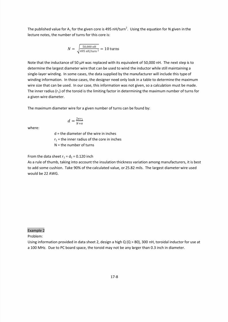
The published value for AL for the given core is 495 nH/turn2. Using the equation for N given in the
lecture notes, the number of turns for this core is:
= 50,000 nH
495 nH/turn 2= 10 turns
Note that the inductance of 50 μH was replaced with its equivalent of 50,000 nH. The next step is to
determine the largest diameter wire that can be used to wind the inductor while still maintaining a
single-layer winding. In some cases, the data supplied by the manufacturer will include this type of
winding information. In those cases, the designer need only look in a table to determine the maximum
wire size that can be used. In our case, this information was not given, so a calculation must be made.
The inner radius (r1) of the toroid is the limiting factor in determining the maximum number of turns for
a given wire diameter.
The maximum diameter wire for a given number of turns can be found by:
=21
+
where:
d = the diameter of the wire in inches
r1 = the inner radius of the core in inches
N = the number of turns
From the data sheet r1 = d2 = 0.120 inch
As a rule of thumb, taking into account the insulation thickness variation among manufacturers, it is best
to add some cushion. Take 90% of the calculated value, or 25.82 mils. The largest diameter wire usedwould be 22 AWG.
Example 2
Problem:
Using information provided in data sheet 2, design a high Q (Q > 80), 300 nH, toroidal inductor for use at
a 100 MHz. Due to PC board space, the toroid may not be any larger than 0.3 inch in diameter.

8/3/2019 Lecture 17 the Toroidal Inductor
http://slidepdf.com/reader/full/lecture-17-the-toroidal-inductor 9/15
17-9
Solution:
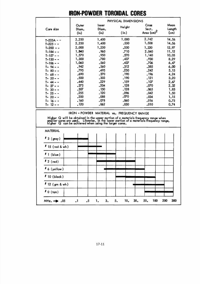
The second data sheet is an excerpt from an Amidon Associates iron powder toroidal core data sheet.
The recommended operating frequencies for various materials are shown in the Iron-Powder vs.
Frequency Range graph. Either material No. 12 or material No. 10 seems to be well suited for operation
at 100 MHz. Elsewhere on the data sheet, material No. 12 is listed an IRN-8. (IRN-8 is described in table
17.2 of the lecture notes. Material No. 10 is not described so choose material No. 12.
Under the heading of Iron-Powder Toroidal Cores, the data sheet list the physical dimensions of the
toroids along with the vaue of AL for each. Note that this particular company chooses to specify AL in
μH/100 turns rather than μH/100 turns2. The conversion factor between their value of AL and AL in
nH/turn2 is to divide their value of AL by 10. The T-8—12 core with an AL of 22 μH/100 turns is equal to
2.2 nH/turn2.
The data sheet list a set of Q-curves for the cores listed in the preceding charts. All the curves shown
indicate Qs that are greater than 80 at 100 MHz.
Choose the largest core available that will fit in the allotted PC board area. The core you should have
chosen is the number T-25-12, with an outer diameter of 0.255 inch.
AL = 12 μH/100 t
AL = 1.2 μH/100 t
Using the equation we have for N.
= = 300
1.2= 15.81 16 turns
The chart of Number of turns vs. Wire size and Core Size on the data sheet indicates that for a T-25 size
core, the largest wire size we can use in No. 28 AWG to wind this core.

8/3/2019 Lecture 17 the Toroidal Inductor
http://slidepdf.com/reader/full/lecture-17-the-toroidal-inductor 10/15
17-10
8/3/2019 Lecture 17 the Toroidal Inductor
http://slidepdf.com/reader/full/lecture-17-the-toroidal-inductor 11/15
17-11

8/3/2019 Lecture 17 the Toroidal Inductor
http://slidepdf.com/reader/full/lecture-17-the-toroidal-inductor 12/15
17-12

8/3/2019 Lecture 17 the Toroidal Inductor
http://slidepdf.com/reader/full/lecture-17-the-toroidal-inductor 13/15
17-13

8/3/2019 Lecture 17 the Toroidal Inductor
http://slidepdf.com/reader/full/lecture-17-the-toroidal-inductor 14/15
17-14

8/3/2019 Lecture 17 the Toroidal Inductor
http://slidepdf.com/reader/full/lecture-17-the-toroidal-inductor 15/15
17-15


![PHY204 Lecture 29 · 2020-04-02 · PHY204 Lecture 29 [rln29] Inductor and Inductance Inductor (de vice): A wire that is w ound into N tur ns of some shape and area. The current I](https://img.dokumen.tips/doc/110x75/5f7ccc378ccd537b2318e733/phy204-lecture-29-2020-04-02-phy204-lecture-29-rln29-inductor-and-inductance.jpg)


