Embed Size (px)
Citation preview

UNIVERSITI PUTRA MALAYSIA
DESIGN AND DEVELOPMENT OF BOOST A CONVERTER USING PLANAR INDUCTOR FOR DUAL SUPPLY AUTOMOTIVE SYSTEM
SHASHIKUMAR A/L KRISHNAN
FK 2008 21
DESIGN AND DEVELOPMENT OF BOOST A CONVERTER USING PLANAR INDUCTOR FOR DUAL SUPPLY
AUTOMOTIVE SYSTEM
By
SHASHIKUMAR A/L KRISHNAN
Thesis Submitted to the School of Graduate Studies, University Putra Malaysia, in Fulfillment of the Requirement for the Degree of Master of Science
APRIL 2008

DEDICATION
With appreciation and respect
this thesis is dedicated
to my parents and
to my wife.
I owe my country a great debt.
ii
Abstract of thesis presented to the Senate of University Putra Malaysia in fulfillment of the requirement for the degree of Master of Science
DESIGN AND DEVELOPMENT OF BOOST A CONVERTER USING PLANAR INDUCTOR FOR DUAL SUPPLY
AUTOMOTIVE SYSTEM
By
Shashikumar a/l Krishnan
APRIL 2008
Chairman: Norman Bin Mariun, PhD,
Faculty: Engineering Today, innovation in electronic automobile components has resulted in the need for
higher voltage power supplies. In future automotive vehicles will have 36V operating
system. In order to convert to 36V operating system, a 14V/42V dual power supply
design is currently being tested and implemented in electric and hybrid vehicles. In
future all electrical and diesel vehicle components will be using 42V electronic
components ( bulbs, alarms, radio, ICU etc). Boost converter 14V step up to 42V will
be an essential component in all vehicles.
This work comprises of designing an efficient boost converter which can be easily
manufactured and will work for dual supply electrical vehicle as well as diesel
vehicle. Current available electric vehicle converters are either buck or bidirectional
iii

type. Various topologies have been used in electric vehicle converters. In the early
days, auto-transformer topology was common, followed by toroidal inductor which
became popular. Currently E-I planar core with spiral PCB inductor are being
gradually applied in industry. Jumpstart post embedded in the converter is another
key area of electric vehicle converters with dual power supply being studied.
The scopes of this research are to evaluate and experiment ideas before building and
testing a design with auxiliary start (cracking) aid boost converter that would be
compatible the 14V/42V power net. In this research dual supply vehicle boost
converter prototype designs were experimented. The work consists of design study of
CCM DC-DC Boost Converter with E-I Planar core spiral PCB inductor using a SMT
UCC38C43D PWM chip controller. The experimental results are obtained using the
Planar spiral inductor DC-DC boost converter, designed to operate in CCM for 120W
with an efficient of 85% and output voltage ripple of 5%.
iv
Abstrak tesis yang dikemukakan kepada Senat Universiti Putra Malaysia sebagai memenuhi keperluan syarat bagi pengajian Sarjana Sains
MEREKABENTUK DAN PERBANGUNAN SEBUAH PENUKAR GALAK LONJAKAN YANG MENGGUNAKAN PLANAR
INDUKTOR UNTUK SISTEM KENDERAAN DWI BEKALAN
oleh
Shashikumar A/L Krishnan
JUN 2008
Pengerusi: Norman Bin Mariun, PhD
Fakulti: Kejuruteraan Pada masa kini, inovasi dalam komponen elektronik motokar telah menyebabkan
keperluan untuk menggunakan bekalan kuasa voltan yang lebih tinggi. Pada masa
hadapan sistem operasi semua kenderaan bermotor akan menggunakan 36V. Untuk
membolehkan sistem beroperasi pada 36V, sebuah 14V/42V rekabentuk bekalan
dwikuasa telah dipasangkan buat sementara waktu (tempoh peralihan) pada
kenderaan elektrik dan hibrid. Untuk mengelakkan pembaziran dan mengurangkan
kos, komponen elektrik dalam kenderaan elektrik dan disel masa hadapan akan
menggunakan komponen elektrik pada tahap kuasa yang sama iaitu 42V (contohnya
mentol, alat penggera, radio, ICU dll.) Penukar galak 14V meningkat ke 42V akan
menjadi sebuah komponen yang penting untuk semua kenderaan.
v
Projek ini meliputi merekabentuk sebuah penukar galak yang efisyen dan yang boleh
dibuat dengan mudah serta berfungsi untuk dwibekalan kenderaan elektrik dan disel.
Penukar kenderaan elektrik yang sedia ada sekarang adalah jenis penurun atau pun
dwi-arah sahaja. Terdapat pelbagai topologi yang digunakan dalam penukar elektrik
kenderaan. Pada mulanya topologi pengubah-auto telah digunakan dengan luasnya
diikuti dengan induktor teroidal. Pada masa kini E-I Planer bersama induktor spiral
PCB mula digunakan dalam industri. Penggunaan kemudahan ‘jumpstart’ yang
tertanam dalam penukar merupakan satu aspek kajian utama dalam penukar
kenderaan elektrik yang menggunakan dwikuasa.
Liputan penyelidikan ini adalah untuk menilai dan menguji idea sebelum membina
dan menguji sebuah rekabentuk pembantu penghidup kenderaan yang serasi dengan
14V/42V power net. Sebuah rekabentuk topologi dan litar penukar galak kenderaan
dwibekalan telah dibina dan diuji untuk projek ini. Projek ini meliputi kajian
rekabentuk sebuah litar CCM penukar galak kenderaan dwibekalan, teras ‘E-I
keeping’ pusar PCB induktor dengan mengunakan SMT UCC38C43D PWM
bersepadu. Rumusannya, kajian ini menunjukkan bahawa penukar galak yang
direkabentuk itu telah memenuhi matlamatnya dengan mencapai kecekapan pada
85% and keralatan voltan keluaran sebanyak 5% sahaja.
vi

ACKNOWLEDGEMENTS
My deepest gratitude and respect to my parents for their support, guidance,
encouragements and advice and to my wife for her assistance in typing.
Finally, I would like to express my deep appreciation and profound gratitude to my
supervisors, Professor Dr. Norman Bin Mariun, Dr Mohd Hamiruce bin Marhaban
and Mohd Amran bin Mohd Radzi for their guidance, encouragements and advice
throughout my study.
vii
I certify that an Examination Committee has met on _______ 2008 to conduct the final examination of Shashikumar a/l Krishnan on his Master of Science thesis entitled “Designing and Development of Boost Converter using Planar Inductor for Dual Supply Automotive System” in accordance with Universiti Pertanian Malaysia (Higher Degree) Act 1980 and Universiti Pertanian Malaysia (Higher Degree) Regulations 1981. The Committee recommends that the candidate be awarded the relevant degree. Members of the Examination Committee are as follows: Chairman, PhD. Professor Faculty of Engineering Universiti Putra Malaysia (Chairman) Examiner 1, PhD. Associate Professor Faculty of Engineering Universiti Putra Malaysia (Internal Examiner) Examiner 2, PhD Associate Professor Faculty of Engineering Universiti Putra Malaysia (Internal Examiner) External Examiner, PhD. Professor Faculty of Graduate Studies University Putra Malaysia (External Examiner) ———————————————
HASANAH MOHD. GHAZALI, PhD Professor/Deputy Dean School of Graduate Studies
Universiti Putra Malaysia
Date:
viii
This thesis was submitted to the Senate of Universiti Putra Malaysia and has been accepted as fulfillment of the requirement for the degree of Master of Science. The members of the Supervisor Committee were as follows Norman Bin Mariun, PhD, PEng. Professor Faculty of Engineering Universiti Putra Malaysia (Chairman) Mohd Hamiruce Bin Marhaban, PhD Lecturer Faculty of Engineering Universiti Putra Malaysia (Member) Mohd Amran Bin Mohd Radzi, MSc Lecturer Faculty of Engineering Universiti Putra Malaysia (Member) ———————————————
AINI IDERIS, PhD Professor and Dean School of Graduate Studies Universiti Putra Malaysia
Date: 11 September 2008
ix

DECLARATION
I hereby declare that the thesis is based on my original work except for quotations and citations, which have been duly acknowledged. I also declare that it has not been previously concurrently submitted for any other degree at UPM or other institutions.
SHASHIKUMAR A/L KRISHNAN
Date: 10 September 2008
x
TABLE OF CONTENTS
DEDICATION ABSTRACT ABSTRAK ACKNOWLEDGEMENTS APPROVAL DECLARATION LIST OF TABLES LIST OF FIGURES LIST OF ABBREVIATIONS
Page
ii iii v vii viii x xiii xv xvii
Chapter
1 INTRODUCTION 1 1.1 Background 1 1.2 The rule Power Net Voltage 2 1.3 Electrical Systems in Electric Vehicles 4 1.4 Problem statement 7 1.5 Aim and Objective 8 1.6 Scope of work 8 1.7 Thesis layout
2 LITERATURE REVIEW9
2.1 Electric Vehicle Buck Converter 2.1.1 Resonant Buck Converter 2.1.2 Simpler Topologies Step Down Circuits 2.1.3 Non-Isolated DC-DC Buck Converter 2.1.4 DC-DC Buck Converter with POT-CORE (3F2) Inductor 2.1.5 DC-DC Buck Converter with PIC Controller 2.1.6 Spiral Inductor DC-DC Buck Converter using E-I (3F4) Core
1011 13 16 19 20
2.2 Planar Spiral Inductor DC-DC Boost Converter using E-I Core 27 2.3 Electric Vehicle Bidirectional Converter
2.2.1 Auto Transformer Bidirectional DC-DC Converter 2.2.2 Cascade Bidirectional DC-DC Converter 2.2.3 Resistor Emulating Bidirectional DC-DC Converter 2.2.4 Bidirectional DC-DC Converter 2.2.5 Multiphase Bidirectional DC-DC Converter
2.2.6 Capacitive DC-DC Converter
4041 43 44 47 50
2.4 Fuel Cell EV Multifunction Bidirectional Converter 51 2.5 Jump Post for Electric Vehicle with 42V bus line 52 2.6 Summary
53
xi
3 METHODOLOGY 3.1 Introduction 55 3.2 Theoretical Model Design 57 3.3 Component Choice 72 3.4 Total Power Loss 76 4 RESULTS AND DISCUSSION 4.1 Introduction 79 4.2 Optimized Parameters 80 4.3 Experiment Results 4.4 Load Variation Test 4.5 Data Measurement 4.6 Efficiency Comparison
8286 86 88
5 CONCLUSION AND RECOMMENDATIONS FOR FUTURE WORK 5.1 Conclusion 89 5.2 Recommendations for future work 90
REFERENCES/BIBLIOGRAPHY 92APPENDIX A 95BIODATA OF STUDENT 123
xii
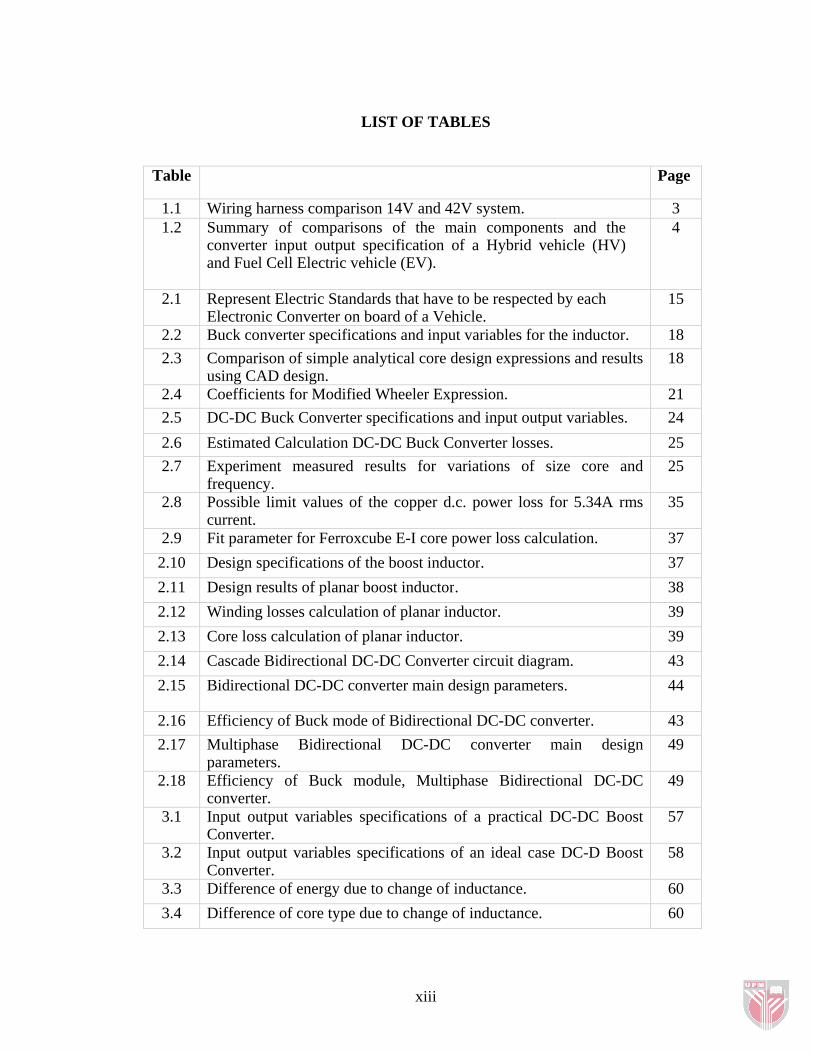
LIST OF TABLES
Table Page
1.1 Wiring harness comparison 14V and 42V system. 31.2 Summary of comparisons of the main components and the
converter input output specification of a Hybrid vehicle (HV) and Fuel Cell Electric vehicle (EV).
4
2.1 Represent Electric Standards that have to be respected by each Electronic Converter on board of a Vehicle.
15
2.2 Buck converter specifications and input variables for the inductor. 182.3 Comparison of simple analytical core design expressions and results
using CAD design. 18
2.4 Coefficients for Modified Wheeler Expression. 212.5 DC-DC Buck Converter specifications and input output variables. 242.6 Estimated Calculation DC-DC Buck Converter losses. 252.7 Experiment measured results for variations of size core and
frequency. 25
2.8 Possible limit values of the copper d.c. power loss for 5.34A rms current.
35
2.9 Fit parameter for Ferroxcube E-I core power loss calculation. 372.10 Design specifications of the boost inductor. 372.11 Design results of planar boost inductor. 382.12 Winding losses calculation of planar inductor. 392.13 Core loss calculation of planar inductor. 392.14 Cascade Bidirectional DC-DC Converter circuit diagram. 432.15 Bidirectional DC-DC converter main design parameters. 44
2.16 Efficiency of Buck mode of Bidirectional DC-DC converter. 432.17 Multiphase Bidirectional DC-DC converter main design
parameters. 49
2.18 Efficiency of Buck module, Multiphase Bidirectional DC-DC converter.
49
3.1 Input output variables specifications of a practical DC-DC Boost Converter.
57
3.2 Input output variables specifications of an ideal case DC-D Boost Converter.
58
3.3 Difference of energy due to change of inductance. 603.4 Difference of core type due to change of inductance. 60
xiii

3.5 AL measured in combination with plate (PLT) for few types of core. 623.6 AL measured in combination with plate (PLT) for E32 core only. 623.7 Operating frequency and inductance finalized choice for Planar
Spiral DC-DC Boost Converter. 62
3.8 Final parameters for each type core choice. 703.9 Fit parameter to calculate the power loss density by
Ferroxcube. 71
3.10 Calculated component losses from datasheet and formulas. 764.1 Optimized parameters and values of the prototype DC-DC Boost
Converter. 80
4.2 List of instruments used for this experiment. 814.3 The load variation effects to the current, power and efficiency to a
fixed input output voltage sets Vin = 12V, Vout = 36V. 87
4.4 The load variation effects to the current, power and efficiency to a fixed input output voltage sets Vin = 14V, Vout = 42V.
87
xiv
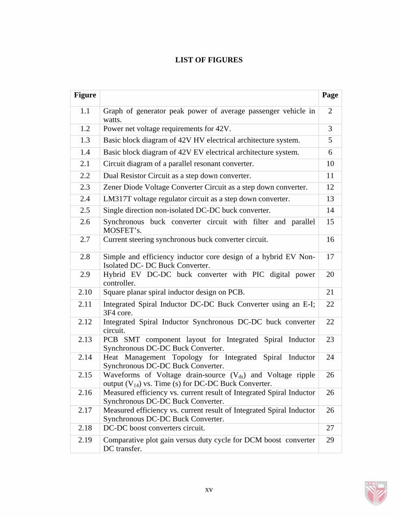
LIST OF FIGURES
Figure Page
1.1 Graph of generator peak power of average passenger vehicle in watts.
2
1.2 Power net voltage requirements for 42V. 31.3 Basic block diagram of 42V HV electrical architecture system. 51.4 Basic block diagram of 42V EV electrical architecture system. 62.1 Circuit diagram of a parallel resonant converter. 102.2 Dual Resistor Circuit as a step down converter. 112.3 Zener Diode Voltage Converter Circuit as a step down converter. 122.4 LM317T voltage regulator circuit as a step down converter. 132.5 Single direction non-isolated DC-DC buck converter. 142.6 Synchronous buck converter circuit with filter and parallel
MOSFET’s. 15
2.7 Current steering synchronous buck converter circuit. 16
2.8 Simple and efficiency inductor core design of a hybrid EV Non-Isolated DC- DC Buck Converter.
17
2.9 Hybrid EV DC-DC buck converter with PIC digital power controller.
20
2.10 Square planar spiral inductor design on PCB. 212.11 Integrated Spiral Inductor DC-DC Buck Converter using an E-I;
3F4 core. 22
2.12 Integrated Spiral Inductor Synchronous DC-DC buck converter circuit.
22
2.13 PCB SMT component layout for Integrated Spiral Inductor Synchronous DC-DC Buck Converter.
23
2.14 Heat Management Topology for Integrated Spiral Inductor Synchronous DC-DC Buck Converter.
24
2.15 Waveforms of Voltage drain-source (Vds) and Voltage ripple output (V14) vs. Time (s) for DC-DC Buck Converter.
26
2.16 Measured efficiency vs. current result of Integrated Spiral Inductor Synchronous DC-DC Buck Converter.
26
2.17 Measured efficiency vs. current result of Integrated Spiral Inductor Synchronous DC-DC Buck Converter.
26
2.18 DC-DC boost converters circuit. 272.19 Comparative plot gain versus duty cycle for DCM boost converter
DC transfer. 29
xv
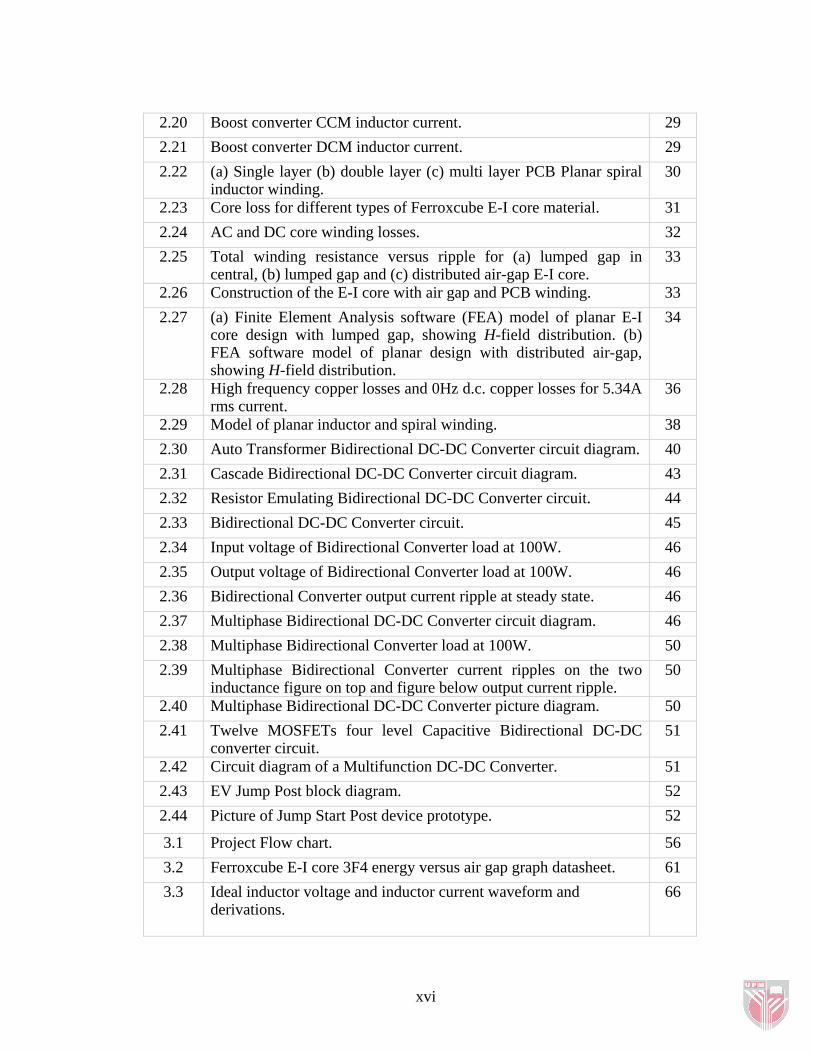
2.20 Boost converter CCM inductor current. 292.21 Boost converter DCM inductor current. 292.22 (a) Single layer (b) double layer (c) multi layer PCB Planar spiral
inductor winding. 30
2.23 Core loss for different types of Ferroxcube E-I core material. 312.24 AC and DC core winding losses. 322.25 Total winding resistance versus ripple for (a) lumped gap in
central, (b) lumped gap and (c) distributed air-gap E-I core. 33
2.26 Construction of the E-I core with air gap and PCB winding. 332.27 (a) Finite Element Analysis software (FEA) model of planar E-I
core design with lumped gap, showing H-field distribution. (b) FEA software model of planar design with distributed air-gap, showing H-field distribution.
34
2.28 High frequency copper losses and 0Hz d.c. copper losses for 5.34A rms current.
36
2.29 Model of planar inductor and spiral winding. 382.30 Auto Transformer Bidirectional DC-DC Converter circuit diagram. 402.31 Cascade Bidirectional DC-DC Converter circuit diagram. 432.32 Resistor Emulating Bidirectional DC-DC Converter circuit. 442.33 Bidirectional DC-DC Converter circuit. 452.34 Input voltage of Bidirectional Converter load at 100W. 462.35 Output voltage of Bidirectional Converter load at 100W. 462.36 Bidirectional Converter output current ripple at steady state. 462.37 Multiphase Bidirectional DC-DC Converter circuit diagram. 462.38 Multiphase Bidirectional Converter load at 100W. 502.39 Multiphase Bidirectional Converter current ripples on the two
inductance figure on top and figure below output current ripple. 50
2.40 Multiphase Bidirectional DC-DC Converter picture diagram. 502.41 Twelve MOSFETs four level Capacitive Bidirectional DC-DC
converter circuit. 51
2.42 Circuit diagram of a Multifunction DC-DC Converter. 512.43 EV Jump Post block diagram. 522.44 Picture of Jump Start Post device prototype. 52
3.1 Project Flow chart. 563.2 Ferroxcube E-I core 3F4 energy versus air gap graph datasheet. 613.3 Ideal inductor voltage and inductor current waveform and
derivations.
66
xvi
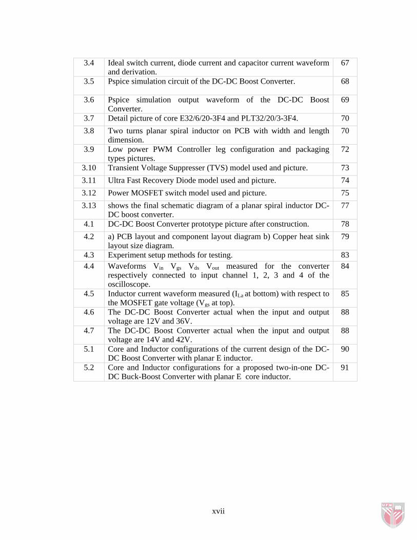
3.4 Ideal switch current, diode current and capacitor current waveform and derivation.
67
3.5 Pspice simulation circuit of the DC-DC Boost Converter.
68
3.6 Pspice simulation output waveform of the DC-DC Boost Converter.
69
3.7 Detail picture of core E32/6/20-3F4 and PLT32/20/3-3F4. 703.8 Two turns planar spiral inductor on PCB with width and length
dimension. 70
3.9 Low power PWM Controller leg configuration and packaging types pictures.
72
3.10 Transient Voltage Suppresser (TVS) model used and picture. 733.11 Ultra Fast Recovery Diode model used and picture. 743.12 Power MOSFET switch model used and picture. 753.13 shows the final schematic diagram of a planar spiral inductor DC-
DC boost converter. 77
4.1 DC-DC Boost Converter prototype picture after construction. 784.2 a) PCB layout and component layout diagram b) Copper heat sink
layout size diagram. 79
4.3 Experiment setup methods for testing. 834.4 Waveforms Vin Vgs Vds Vout measured for the converter
respectively connected to input channel 1, 2, 3 and 4 of the oscilloscope.
84
4.5 Inductor current waveform measured (ILa at bottom) with respect to the MOSFET gate voltage (Vgs at top).
85
4.6 The DC-DC Boost Converter actual when the input and output voltage are 12V and 36V.
88
4.7 The DC-DC Boost Converter actual when the input and output voltage are 14V and 42V.
88
5.1 Core and Inductor configurations of the current design of the DC-DC Boost Converter with planar E inductor.
90
5.2 Core and Inductor configurations for a proposed two-in-one DC-DC Buck-Boost Converter with planar E core inductor.
91
xvii
xviii
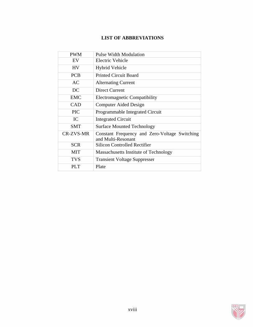
LIST OF ABBREVIATIONS
PWM Pulse Width ModulationEV Electric VehicleHV Hybrid VehiclePCB Printed Circuit BoardAC Alternating CurrentDC Direct Current
EMC Electromagnetic CompatibilityCAD Computer Aided DesignPIC Programmable Integrated Circuit IC Integrated Circuit
SMT Surface Mounted TechnologyCR-ZVS-MR Constant Frequency and Zero-Voltage Switching
and Multi-Resonant SCR Silicon Controlled RectifierMIT Massachusetts Institute of TechnologyTVS Transient Voltage SuppresserPLT Plate

CHAPTER 1
INTRODUCTION
1.1 Background
In the early days of the automobile, a 6V battery was used to power various electronic
components. In the 1950’s, powerful engines like the V-8 were being introduced
along with electronic components like radios and higher power headlamps. In turn, a
larger power source was needed to facilitate these new introductions. Therefore, the
automobile industry made a transition to a higher energy 12V battery. (Example in
1960’s: mass-produced motor car power rail voltage change accords during VW-
Beetle making in 1965) Today, innovations and transitions to electrical power are
causing the automobile industry to face the same sort of situation faced in the 50’s.
Therefore, manufacturers are investigating a dual voltage power source consisting of
both 12V and 36V batteries. This power source would allow the introduction of more
electro-mechanical systems like electronic brakes and electronic power steering.
However, some components like incandescent light bulbs and motors prefer low
voltage operation. Therefore, these lower components could be powered by the 12V
battery or by the 36V battery if the voltage was transformed to 12V accurately.
1
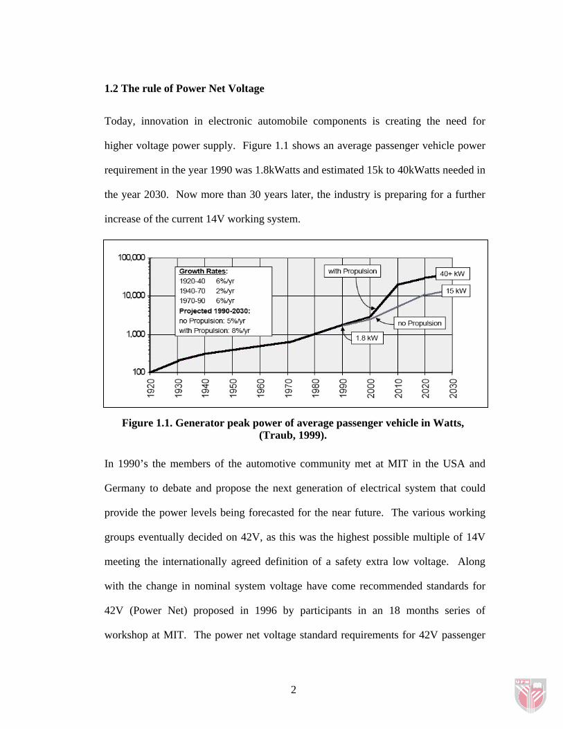
1.2 The rule of Power Net Voltage Today, innovation in electronic automobile components is creating the need for
higher voltage power supply. Figure 1.1 shows an average passenger vehicle power
requirement in the year 1990 was 1.8kWatts and estimated 15k to 40kWatts needed in
the year 2030. Now more than 30 years later, the industry is preparing for a further
increase of the current 14V working system.
Figure 1.1. Generator peak power of average passenger vehicle in Watts, (Traub, 1999).
In 1990’s the members of the automotive community met at MIT in the USA and
Germany to debate and propose the next generation of electrical system that could
provide the power levels being forecasted for the near future. The various working
groups eventually decided on 42V, as this was the highest possible multiple of 14V
meeting the internationally agreed definition of a safety extra low voltage. Along
with the change in nominal system voltage have come recommended standards for
42V (Power Net) proposed in 1996 by participants in an 18 months series of
workshop at MIT. The power net voltage standard requirements for 42V passenger
2
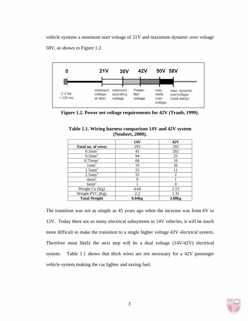
vehicle systems a minimum start voltage of 21V and maximum dynamic over voltage
58V, as shown in Figure 1.2.
Figure 1.2. Power net voltage requirements for 42V (Traub, 1999).
Table 1.1. Wiring harness comparison 14V and 42V system
(Neubert, 2000).
14V 42V Total no. of wires 293 293
0.3mm2 41 202 0.5mm2 94 25
0.75mm2 68 16 1mm2 19 36
1.5mm2 25 11 2.5mm2 35 2 4mm2 9 1 6mm2 1 0
Weight Cu (Kg) 4.64 2.53 Weight PVC (Kg) 2.2 1.35
Total Weight 6.84kg 3.88kg
The transition was not as simple as 45 years ago when the increase was from 6V to
12V. Today there are so many electrical subsystems in 14V vehicles, it will be much
more difficult to make the transition to a single higher voltage 42V electrical system.
Therefore most likely the next step will be a dual voltage (14V/42V) electrical
system. Table 1.1 shows that thick wires are not necessary for a 42V passenger
vehicle system making the car lighter and saving fuel.
3
1.3 Electrical Systems in Electric Vehicles Traditional architecture of 14V system diesel vehicle has a 14V alternator (generator)
connected to the engine to charge the electrical system of the vehicle. In 42V Hybrid
Vehicle (HV) the 42V alternator is connected to the 36V battery and the 42V
electrical system as shown in Figure 1.3 (a). A 42V starter is also connected to the
42V electrical system of the hybrid electrical vehicle. Complete circuit diagram of
42V HV system with jump start post is shown in Figure 1.3 (b). The circuit main
electronics components are 14V/42V bidirectional DC-DC converter, AC-DC
inverter and jump start post. The DC-DC converter will be most of the time running
in buck mode during the car in run mode. The boost mode only runs during starting
(cranking engine) process to assist the starter motor.
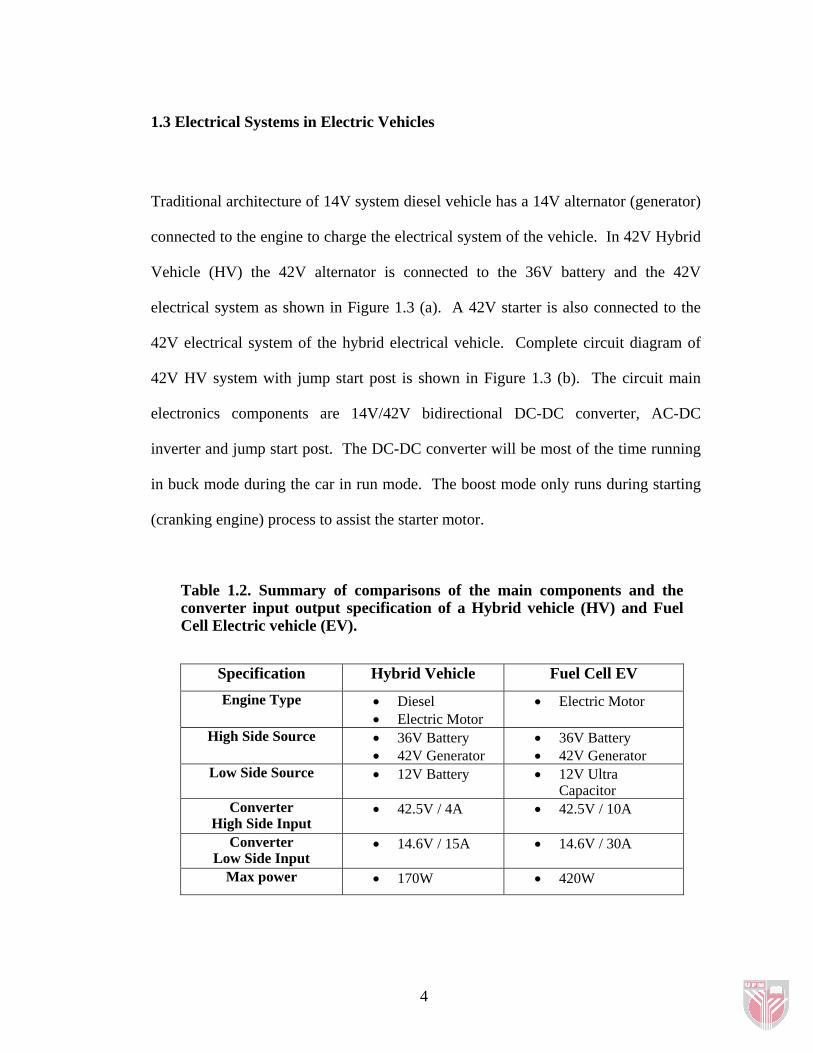
Table 1.2. Summary of comparisons of the main components and the converter input output specification of a Hybrid vehicle (HV) and Fuel Cell Electric vehicle (EV).
Specification Hybrid Vehicle Fuel Cell EV Engine Type • Diesel
• Electric Motor • Electric Motor
High Side Source • 36V Battery • 42V Generator
• 36V Battery • 42V Generator
Low Side Source • 12V Battery
• 12V Ultra Capacitor
Converter High Side Input
• 42.5V / 4A
• 42.5V / 10A
Converter Low Side Input
• 14.6V / 15A
• 14.6V / 30A
Max power • 170W • 420W
4
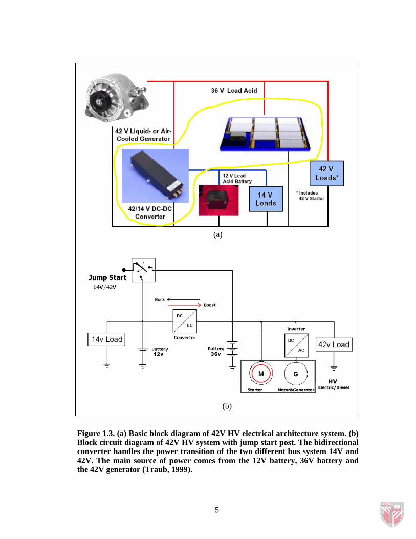
(a)
(b)
Figure 1.3. (a) Basic block diagram of 42V HV electrical architecture system. (b) Block circuit diagram of 42V HV system with jump start post. The bidirectional converter handles the power transition of the two different bus system 14V and 42V. The main source of power comes from the 12V battery, 36V battery and the 42V generator (Traub, 1999).
5
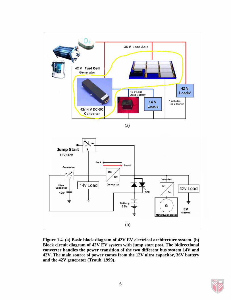
(a)
(b)
Figure 1.4. (a) Basic block diagram of 42V EV electrical architecture system. (b) Block circuit diagram of 42V EV system with jump start post. The bidirectional converter handles the power transition of the two different bus system 14V and 42V. The main source of power comes from the 12V ultra capacitor, 36V battery and the 42V generator (Traub, 1999).
6