Embed Size (px)
Citation preview

LECTURE #13 :3.11 MECHANICS OF MATERIALS F03
INSTRUCTOR : Professor Christine OrtizOFFICE : 13-4022 PHONE : 452-3084WWW : http://web.mit.edu/cortiz/www
• Review : Torsion and Beam Bending 1&2• Beam Bending 3 : Stresses in Beams

1. Torsion : loading of a bar by an external torque or twisting moment that tends to produce rotation about the longitudinal (z) axis of the bar2. Pure Torsion :ASSUMPTIONS :•every cross-section of the bar is identical and subjected to same internal torque•all cross-sections remain plane, the same shape, and the radii remain straight as they rotate around the longitudinal axis•if the angle of rotation is small, the change in length and radius can be neglected •only twisting and pure shear stresses, no bending or warping (assume bar is weightless)•linear elastic, isotropicParameters :L=bar lengthφ=angle of twist at end of barγφz=shear strainδ =shear deformationr=radial coordinatez=axial coordinateR=cross-sectional area radiusT=torqueτφz=shear stress
©20
01 B
rook
s/C
ole,
a d
ivis
ion
of T
hom
son
Lea
rnin
g, In
c. T
hom
sonL
earn
ing ™
is a
trad
emar
k us
ed h
erei
n un
der
licen
se.
©20
01 B
rook
s/C
ole,
a d
ivis
ion
of T
hom
son
Lea
rnin
g, In
c. T
hom
sonL
earn
ing ™
is a
trad
emar
k us
ed h
erei
n un
der
licen
se.
©20
01 B
rook
s/C
ole,
a d
ivis
ion
of T
hom
son
Lea
rnin
g, In
c. T
hom
sonL
earn
ing ™
is a
trad
emar
k us
ed h
erei
n un
der
licen
se.
©20
01 B
rook
s/C
ole,
a d
ivis
ion
of T
hom
son
Lea
rnin
g, In
c. T
hom
sonL
earn
ing ™
is a
trad
emar
k us
ed h
erei
n un
der
licen
se.
τφz (r)= τmax(r/R)
T cross-sectionalarea
τmax
z
z=0z=L
φ
rr=Rr=0
γ
SOLID BAR
=double arrow notation
©20
01 B
rook
s/C
ole,
a d
ivis
ion
of T
hom
son
Lea
rnin
g, In
c. T
hom
sonL
earn
ing ™
is a
trad
emar
k us
ed h
erei
n un
der
licen
se.
©20
01 B
rook
s/C
ole,
a d
ivis
ion
of T
hom
son
Lea
rnin
g, In
c. T
hom
sonL
earn
ing ™
is a
trad
emar
k us
ed h
erei
n un
der
licen
se.
©20
01 B
rook
s/C
ole,
a d
ivis
ion
of T
hom
son
Lea
rnin
g, In
c. T
hom
sonL
earn
ing ™
is a
trad
emar
k us
ed h
erei
n un
der
licen
se.
©20
01 B
rook
s/C
ole,
a d
ivis
ion
of T
hom
son
Lea
rnin
g, In
c. T
hom
sonL
earn
ing ™
is a
trad
emar
k us
ed h
erei
n un
der
licen
se.
Review Lecture 10 : Torsion
δ
rigid support
z
z z
1. Geometrical Statement : d
2. Shear Strain Displacment Relation : =rdz
d 3. Constitutive Law : = =Gr
dz4. Equations of Static Equilibrium (Rotational) :
TLconstant T : =
JG[ radians
rd
G
φ
φ φ
δ φφ
γ
φτ γ
φ
π
=
o o
4
4
4 4o i
2
=180 , 1 rad=57.3 ] J(m ) = polar moment of inertia,
rsolid bar, circular cross-sectional area : J=
2(r -r )
hollow bar : J=2
JGJG(Nm )="torsional rigidity", k(Nm)= ="torsiona
L
π
π
( )z
fz f
l stiffness"
Tr5. Shear Stresses : =
JT r
= =modulus of rupture in torsionJ
φ
φ
τ
τ
DERIVATION:
Review Lecture 10 : Torsion
©2001 Brooks/Cole, a division of Thomson Learning, Inc. Thomson Learning ™ is a trademark used herein under license.©2001 Brooks/Cole, a division of Thomson Learning, Inc. Thomson Learning ™ is a trademark used herein under license.©2001 Brooks/Cole, a division of Thomson Learning, Inc. Thomson Learning ™ is a trademark used herein under license.

I. Basics : BEAM : structural member subjected to lateral loads, i.e. forces or moments having their vectors perpendicular to the axis of the bar
nomenclature :L=length or span, b=width, h=heightNA=neutral axis passes through centroid (x,y=0) of cross-sectionI=moment of inertia of cross section about NA
Review : Beam Theory
x
yz
Lb
h
NAweb
flange
flange
1. simply supported
2. overhanging
P
A ByA=0 yB=0
P
A ByA=0 yB=0
PA
ByA=0, θA=0
I-beamcross-section
rectangularcross-section
II. Types of Supports and Boundary Conditions
NA
web
flange T-beamcross-section
3. cantilever
3 4
rectangular circularbh rI = , I = 12 4
EI=flexural modulus
π
Review : Beam Theory (Cont'd)
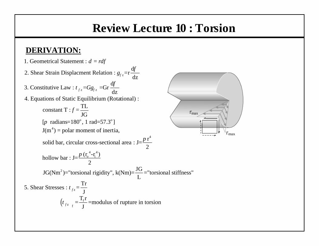
III. Types of Loading
0 •a
0 •a
0 •a
Po
0 •a
slope=k
0 •a
L
L
L
L
L
Mo
Po
concentrated moment or
couple
concentrated load
distributed, uniform load
linearly varying load
parabolically varying load

IV. Successive Integration Method / Shear and Bending Moment Diagrams :
V. Sign Conventions :
Review : Beam Theory (Cont’d)
(+)
V
V
(-)
V
V
(+)
(-)M MM M
compression
tensioncompression
tension
1
1 2
21
2 3
dVq(x) q=- q= loading function
dx
dMV(x) =- q(x)dx+C V= V=shear force
dx
dM(x) = V(x)dx+C x +C M= M=bending moment
C x1(x) = M(x)dx+ +C x+C
EI 5
dxθ
θ
∫
∫
∫3 2
1 23 4
dV =EI =curvature=slope of y-displacement curve
dx
C x C xy(x) = q(x)dx + + +C x +C y=vertical displacement
6 5
θ θ
∫

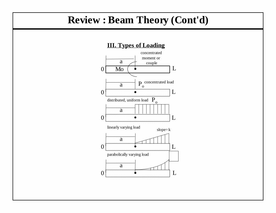
Beam Theory 3 : Normal Stresses and Strains
y
σx (y)x
σy =0
NAMo
(+ moment)
σx (max)c
σx (max)T
x
yz
?
N.A. compression
tension
m p
n q
dθρ
dxe fy
Mo
Mo
Flexure formula :
where : normal stress in x-direction
internal bending momenty = vertical distance from NA axis(see Gere Chapter 12, Appendix D, p 321)I = moment of inertia of cross-sect
ox
x
o
M yI
M
σ
σ
= −
=
=
( ) [ ]
( ) [ ]
maxmaxmax
max
maxmaxmax
ional area
( )
for rectangular beams : 2
( ),
"flexural modulus"
ox
oox x
M x y
Ih
y
M x yM yEI EI
EI
σ
ε ε
= −
=
= − = −
=

Beam Theory (Cont'd) : Shear Stresses and Strains
y
z
NA
22
Derivation in Gere Section 5.8 :
(rectangular cross section)2 4
where : shear stress
shear forceh = height of cross sectional areay= distance from NA
(rectangular cross sect
xy
xy
xy
V h yI
V
τ
τ
τ
= − −
=
=
max
3ion)
2cross sectional area
VA
A
= −
=
τxy(y)x

Beam Theory 3 : Stresses and Strains
x
y
z
y
z

Beam Theory 3 : Stresses and Strains
x
y
z
y
z
?
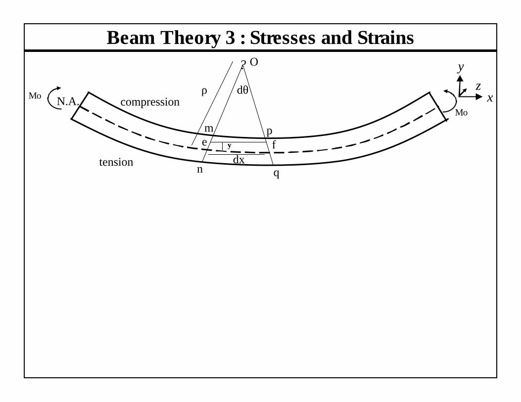
Beam Theory 3 : Stresses and Strains
x
yz
? O
N.A. compression
tension
m p
n q
dθρ
dxe fy
Mo
Mo

Beam Theory 3 : Relate Stress to Moment
y
σx (y)x
σy =0
NAMo
(+ moment)
σx (max)c
σx (max)T