Embed Size (px)
Citation preview

Lecture 10: TDLAS Applications to Energy Conversion
1. Introduction2. Fuel in IC engines – fuel and T
Absorption cross section vsgasoline blend
3. H2O and T in slagging coal gasifier4. H2O in transfer coal gasifier5. NO and CO in coal-fired boiler exhaust6. Future trends – energy conversion
Transport coal gasifier at the National Carbon Capture Center
Wilsonville, AL
2
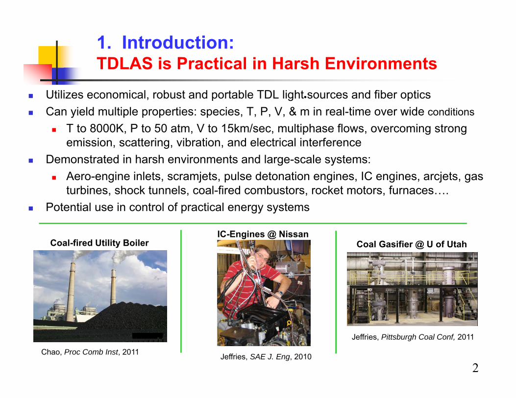
1. Introduction: TDLAS is Practical in Harsh Environments
Utilizes economical, robust and portable TDL light sources and fiber optics Can yield multiple properties: species, T, P, V, & m in real-time over wide conditions
T to 8000K, P to 50 atm, V to 15km/sec, multiphase flows, overcoming strong emission, scattering, vibration, and electrical interference
Demonstrated in harsh environments and large-scale systems: Aero-engine inlets, scramjets, pulse detonation engines, IC engines, arcjets, gas
turbines, shock tunnels, coal-fired combustors, rocket motors, furnaces…. Potential use in control of practical energy systems
.
Coal Gasifier @ U of Utah
Jeffries, Pittsburgh Coal Conf, 2011
Coal-fired Utility Boiler
Chao, Proc Comb Inst, 2011
IC-Engines @ Nissan
Jeffries, SAE J. Eng, 2010
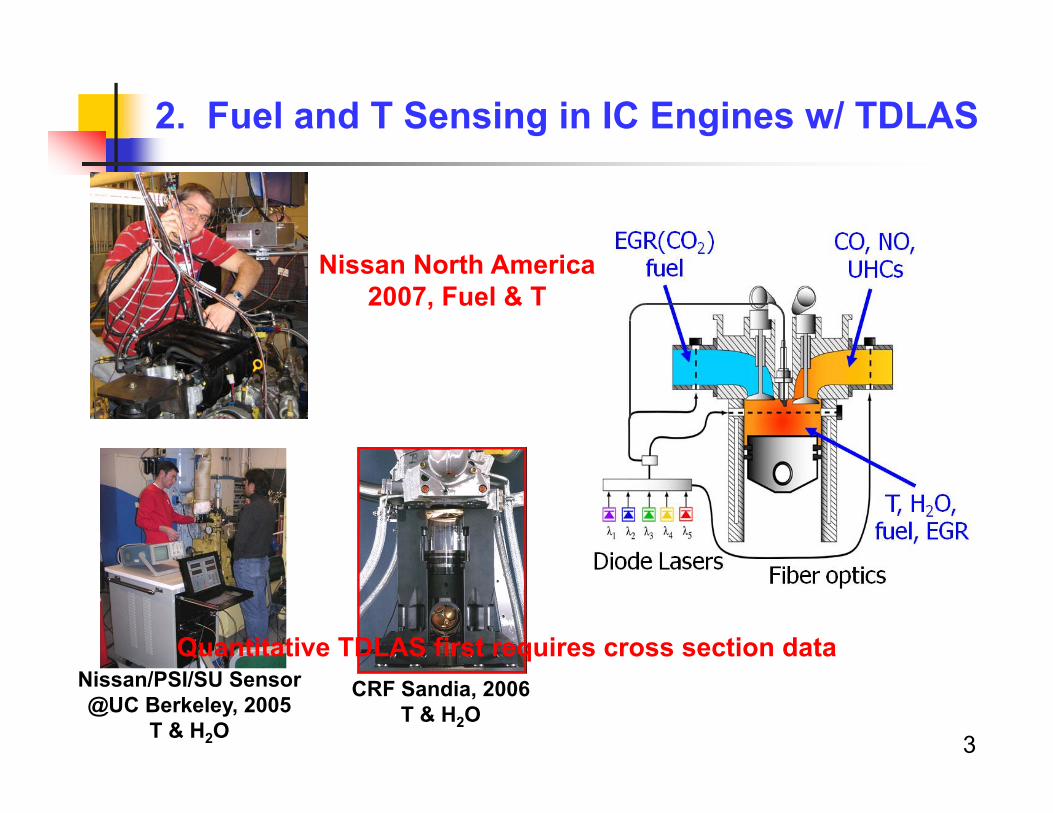
2. Fuel and T Sensing in IC Engines w/ TDLAS
CRF Sandia, 2006T & H2O
Nissan/PSI/SU Sensor@UC Berkeley, 2005
T & H2O
Nissan North America2007, Fuel & T
3
Quantitative TDLAS first requires cross section data
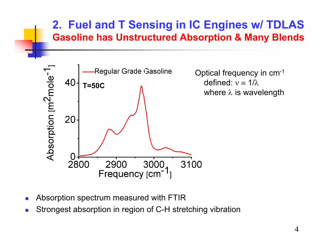
2. Fuel and T Sensing in IC Engines w/ TDLASGasoline has Unstructured Absorption & Many Blends
Absorption spectrum measured with FTIR Strongest absorption in region of C-H stretching vibration
4
Optical frequency in cm-1
defined: 1/where is wavelength
T=50C
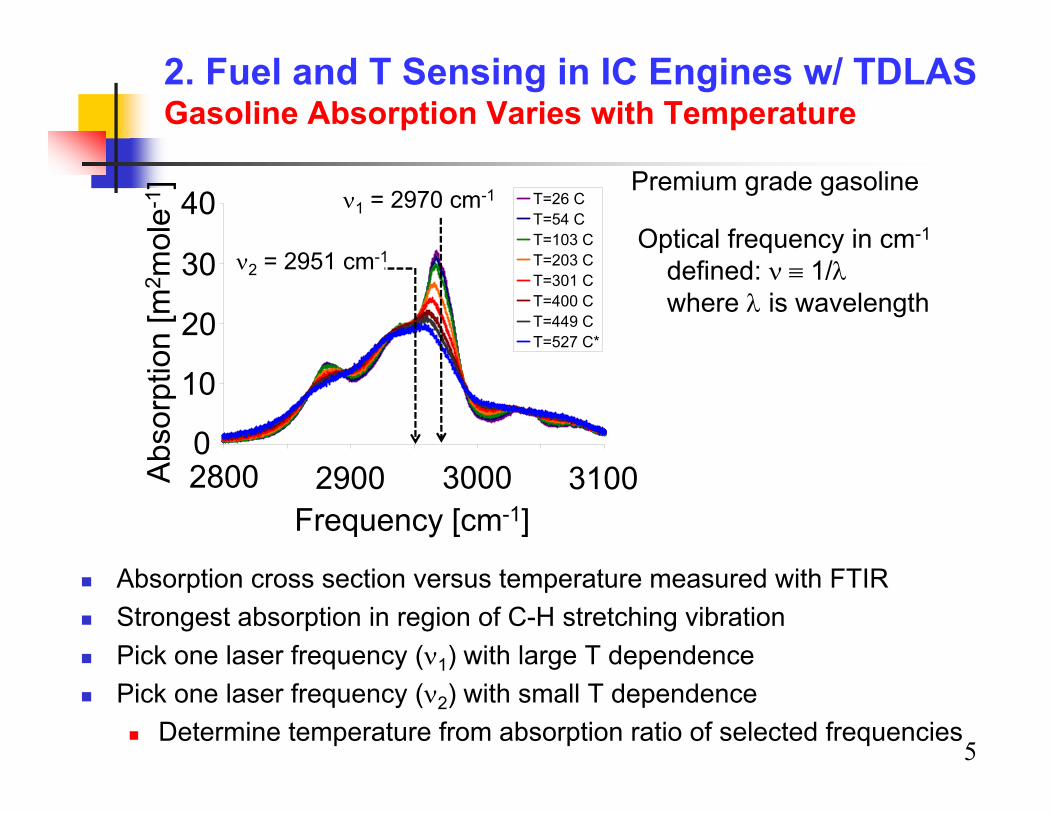
2. Fuel and T Sensing in IC Engines w/ TDLASGasoline Absorption Varies with Temperature
Absorption cross section versus temperature measured with FTIR Strongest absorption in region of C-H stretching vibration Pick one laser frequency (1) with large T dependence Pick one laser frequency (2) with small T dependence
Determine temperature from absorption ratio of selected frequencies5
Premium grade gasolineT=26 CT=54 CT=103 CT=203 CT=301 CT=400 CT=449 CT=527 C*
Frequency [cm-1]2800 2900 3000 31000
10
30
20
40Ab
sorp
tion
[m2 m
ole-
1 ]
2 = 2951 cm-1
1 = 2970 cm-1
Optical frequency in cm-1
defined: 1/where is wavelength

2. Fuel and T Sensing in IC Engines w/ TDLASGasoline Absorption Varies with Blend
Measured (FTIR) absorption cross section varies with blendbut cross-section model can be assembled with knowledge of gasoline composition
2800 2900 3000 31000
20
40
60Ab
sorp
tion
[m2 m
ol-1
]
Frequency [cm-1]
6.3% Aromatic 39% Aromatic
6
Two different blends of premium grade gasoline
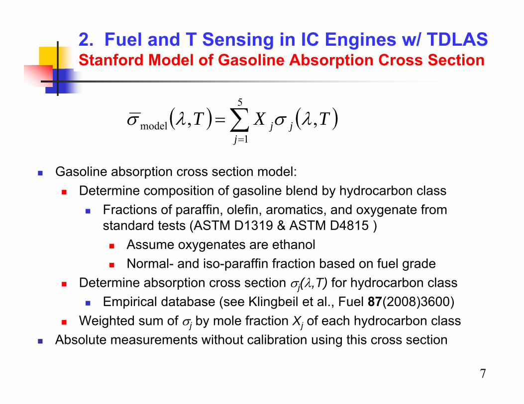
2. Fuel and T Sensing in IC Engines w/ TDLASStanford Model of Gasoline Absorption Cross Section
7
TXTj
jj ,,5
1model
Gasoline absorption cross section model: Determine composition of gasoline blend by hydrocarbon class
Fractions of paraffin, olefin, aromatics, and oxygenate from standard tests (ASTM D1319 & ASTM D4815 ) Assume oxygenates are ethanol Normal- and iso-paraffin fraction based on fuel grade
Determine absorption cross section j(,T) for hydrocarbon class Empirical database (see Klingbeil et al., Fuel 87(2008)3600)
Weighted sum of j by mole fraction Xj of each hydrocarbon class Absolute measurements without calibration using this cross section
8
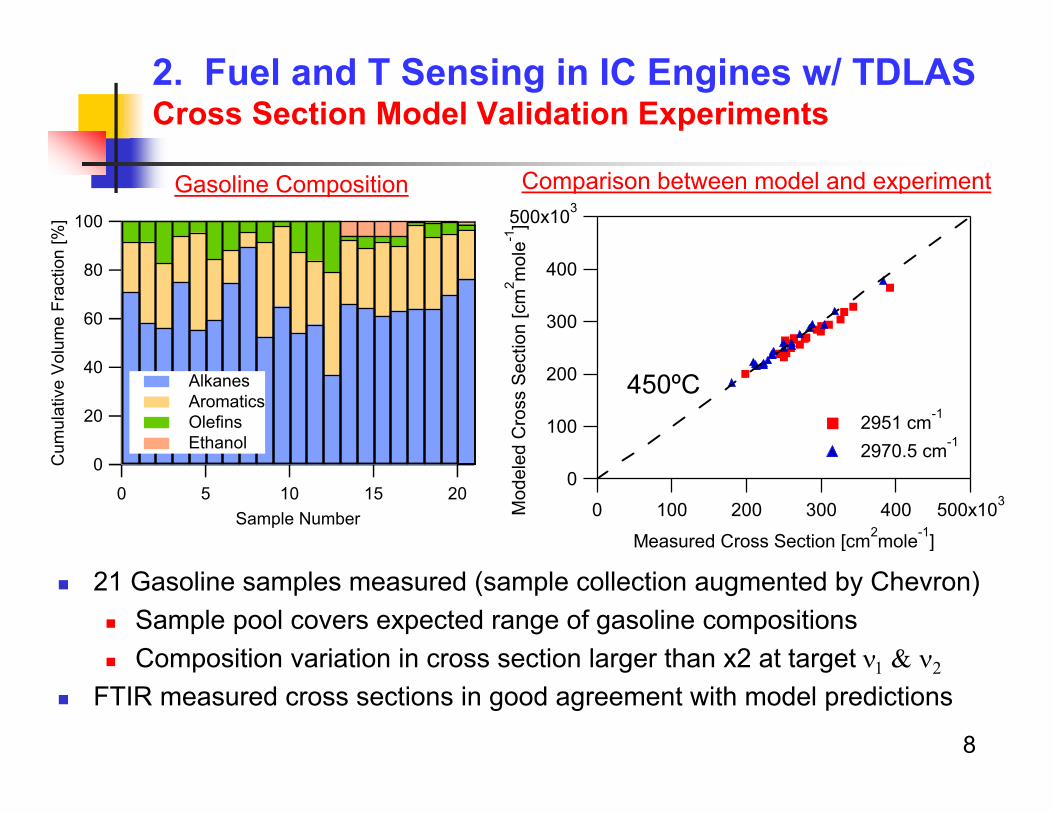
2. Fuel and T Sensing in IC Engines w/ TDLASCross Section Model Validation Experiments
21 Gasoline samples measured (sample collection augmented by Chevron) Sample pool covers expected range of gasoline compositions Composition variation in cross section larger than x2 at target
FTIR measured cross sections in good agreement with model predictions
100
80
60
40
20
0Cum
ulat
ive
Volu
me
Frac
tion
[%]
20151050Sample Number
Alkanes Aromatics Olefins Ethanol
Gasoline Composition500x103
400
300
200
100
0
Mod
eled
Cro
ss S
ectio
n [c
m2 m
ole-1
]500x1034003002001000
Measured Cross Section [cm2mole-1]
2951 cm-1
2970.5 cm-1
450ºC
Comparison between model and experiment
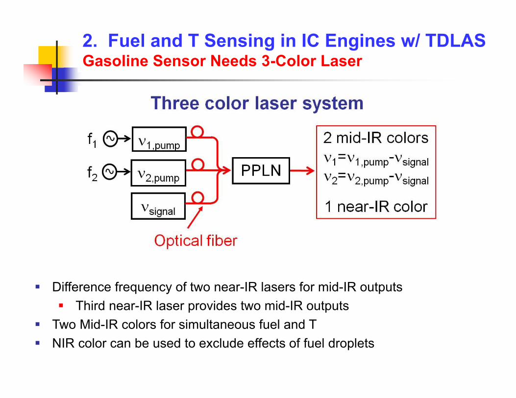
2. Fuel and T Sensing in IC Engines w/ TDLASGasoline Sensor Needs 3-Color Laser
Difference frequency of two near-IR lasers for mid-IR outputs Third near-IR laser provides two mid-IR outputs
Two Mid-IR colors for simultaneous fuel and T NIR color can be used to exclude effects of fuel droplets
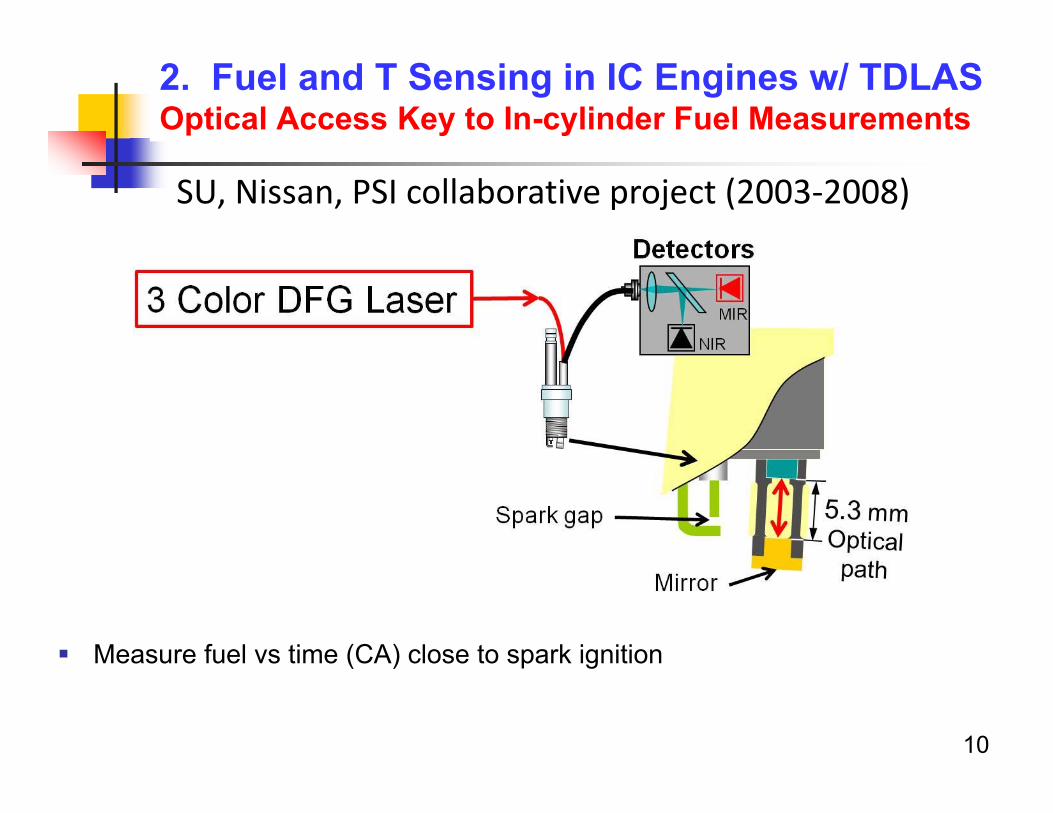
2. Fuel and T Sensing in IC Engines w/ TDLASOptical Access Key to In-cylinder Fuel Measurements
SU, Nissan, PSI collaborative project (2003‐2008)
Measure fuel vs time (CA) close to spark ignition
10
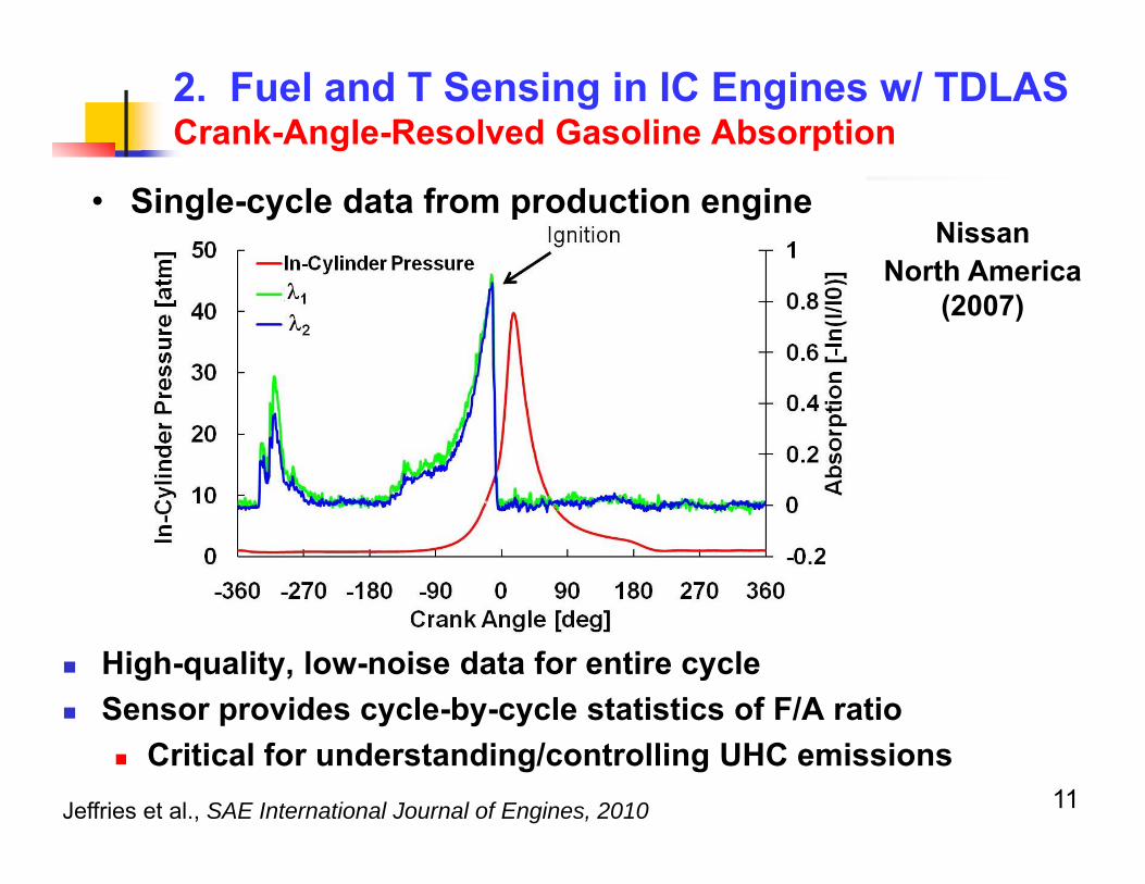
2. Fuel and T Sensing in IC Engines w/ TDLAS Crank-Angle-Resolved Gasoline Absorption
High-quality, low-noise data for entire cycle Sensor provides cycle-by-cycle statistics of F/A ratio
Critical for understanding/controlling UHC emissions
Nissan North America
(2007)
Jeffries et al., SAE International Journal of Engines, 2010 11
• Single-cycle data from production engine
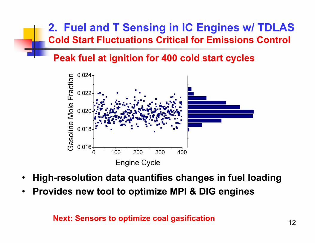
2. Fuel and T Sensing in IC Engines w/ TDLASCold Start Fluctuations Critical for Emissions Control
• High-resolution data quantifies changes in fuel loading• Provides new tool to optimize MPI & DIG engines
Peak fuel at ignition for 400 cold start cycles
12Next: Sensors to optimize coal gasification
1313
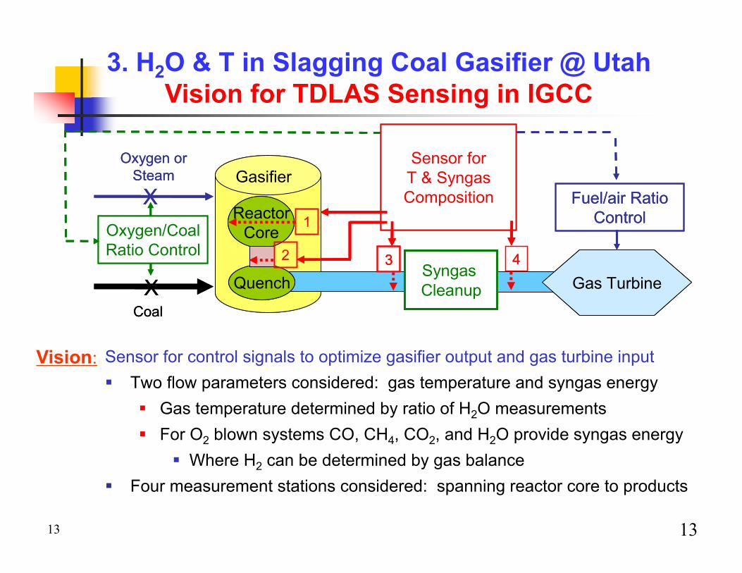
3. H2O & T in Slagging Coal Gasifier @ UtahVision for TDLAS Sensing in IGCC
X
XCoal
Oxygen or Steam
Oxygen/CoalRatio Control
Sensor for T & SyngasComposition
3 4
Fuel/air Ratio Control1
Gasifier
ReactorCore
Quench
2SyngasCleanup Gas Turbine
X
XCoal
Oxygen or Steam
Oxygen/CoalRatio Control
Sensor for T & SyngasComposition
3 4
Fuel/air Ratio Control1
Gasifier
ReactorCore
Quench
ReactorCore
Quench
2SyngasCleanup Gas Turbine
Sensor for control signals to optimize gasifier output and gas turbine input Two flow parameters considered: gas temperature and syngas energy
Gas temperature determined by ratio of H2O measurements For O2 blown systems CO, CH4, CO2, and H2O provide syngas energy
Where H2 can be determined by gas balance Four measurement stations considered: spanning reactor core to products
Vision:
• Measurement locations 1 and 2 provide opportunity for control• Temperature sensing by ratio of H2O absorption lines
• Measurement location 3 monitors syngas heating value• Monitor CO, H2O, CO2, CH4, and assume balance H2
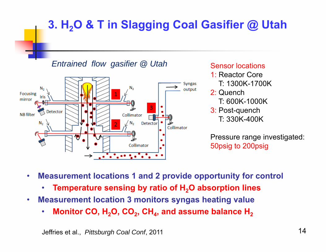
3. H2O & T in Slagging Coal Gasifier @ Utah
Sensor locations1: Reactor Core
T: 1300K-1700K2: Quench
T: 600K-1000K3: Post-quench
T: 330K-400K
Pressure range investigated:50psig to 200psig
Entrained flow gasifier @ Utah
Jeffries et al., Pittsburgh Coal Conf, 2011 14

3. H2O & T in Slagging Coal Gasifier @ Utah Challenge: Absorption Broadened by Pressure
Pressure broadening Blends nearby transitions Eliminates the baseline between transitions
Particulate in the synthesis gas attenuates laser transmission Solution: 1f-normalized WMS: accounts for varying transmission
15
Practical combustion devices often operate at elevated pressures
16
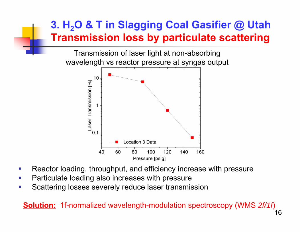
Transmission of laser light at non-absorbing wavelength vs reactor pressure at syngas output
Reactor loading, throughput, and efficiency increase with pressure Particulate loading also increases with pressure Scattering losses severely reduce laser transmission
Solution: 1f-normalized wavelength-modulation spectroscopy (WMS 2f/1f)
3. H2O & T in Slagging Coal Gasifier @ UtahTransmission loss by particulate scattering
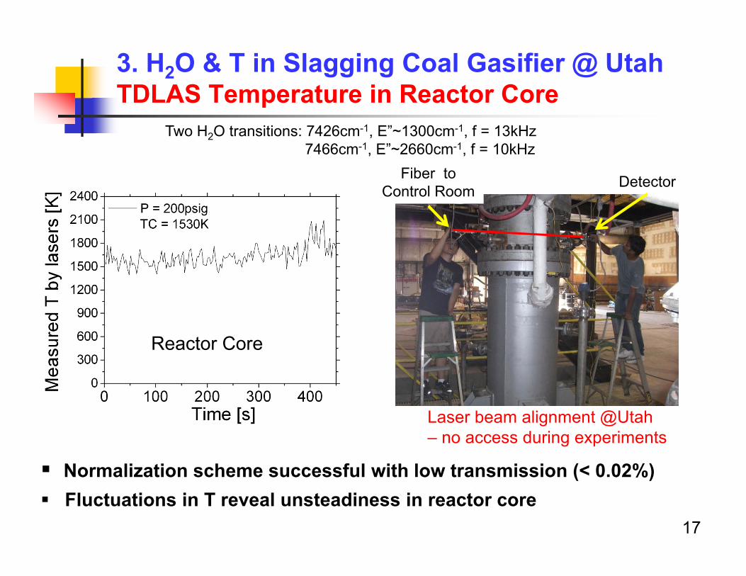
3. H2O & T in Slagging Coal Gasifier @ UtahTDLAS Temperature in Reactor Core
Normalization scheme successful with low transmission (< 0.02%) Fluctuations in T reveal unsteadiness in reactor core
Two H2O transitions: 7426cm-1, E”~1300cm-1, f = 13kHz7466cm-1, E”~2660cm-1, f = 10kHz
17
Reactor Core
DetectorFiber to Control Room
Laser beam alignment @Utah– no access during experiments
18
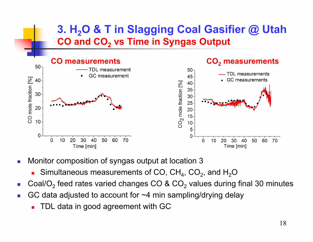
3. H2O & T in Slagging Coal Gasifier @ Utah CO and CO2 vs Time in Syngas Output
Monitor composition of syngas output at location 3 Simultaneous measurements of CO, CH4, CO2, and H2O
Coal/O2 feed rates varied changes CO & CO2 values during final 30 minutes GC data adjusted to account for ~4 min sampling/drying delay
TDL data in good agreement with GC
CO measurements CO2 measurements
19
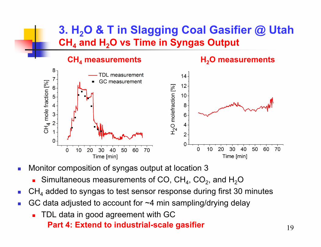
3. H2O & T in Slagging Coal Gasifier @ Utah CH4 and H2O vs Time in Syngas Output
CH4 measurements H2O measurements
Monitor composition of syngas output at location 3 Simultaneous measurements of CO, CH4, CO2, and H2O
CH4 added to syngas to test sensor response during first 30 minutes GC data adjusted to account for ~4 min sampling/drying delay
TDL data in good agreement with GCPart 4: Extend to industrial-scale gasifier

20
4. H2O in Transfer Coal Gasifier @NCCC Large-Scale DoE Demonstration Facility
Instrumentation shelter
Note man-sized figure
NCCC transport gasifier based on a circulating fluidized bed conceptGoal:Laser absorption in situ measurements of moisture and temperature of syngas

4. H2O in Transfer Coal Gasifier @NCCC TDL Sensor Located Downstream of PCD
TDL sensor monitors syngas flow 99 feet downstream of the PCD Small (0.01%) transmission due to beam steering & scattering from ash
Nominal conditions at TDL sensorT~600 KP~220 psig (15 atm)Gas composition
H2O 6-10%CO2 6-10%CO ~12%H2 ~ 8%CH4 ~ 1%Minor species <1%
(e.g., NH3, H2S, SO2…)N2 Balance
21
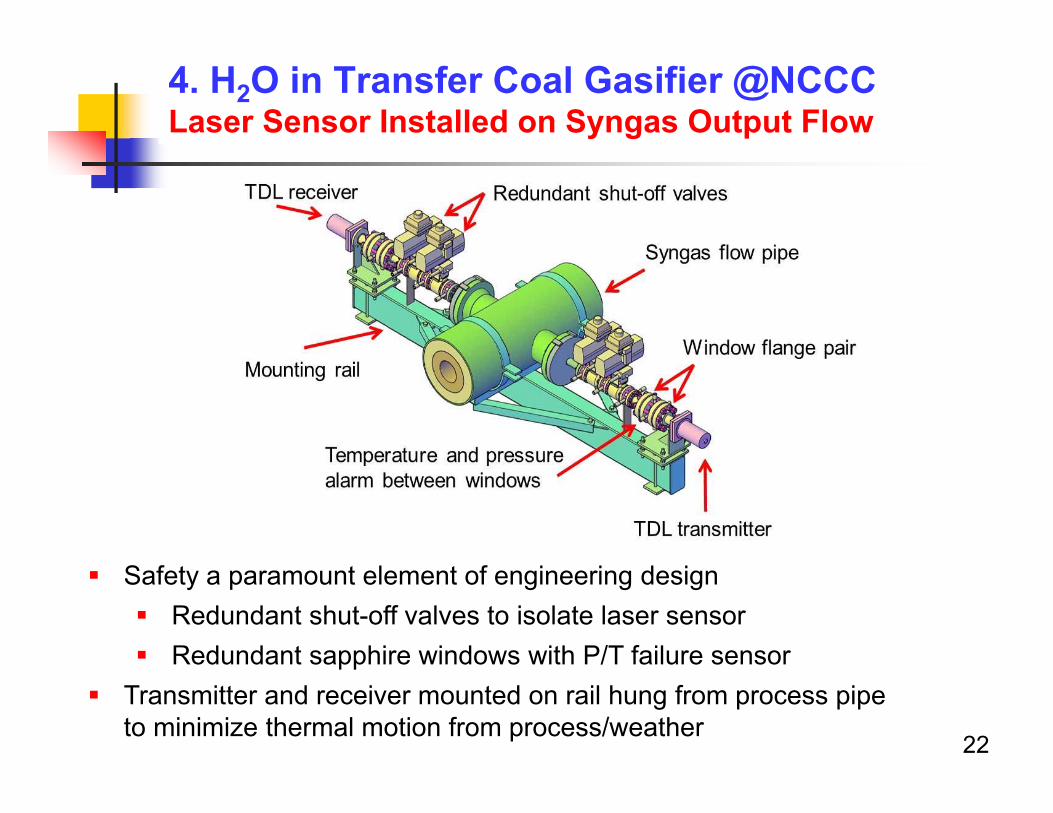
4. H2O in Transfer Coal Gasifier @NCCC Laser Sensor Installed on Syngas Output Flow
22
Safety a paramount element of engineering design Redundant shut-off valves to isolate laser sensor Redundant sapphire windows with P/T failure sensor
Transmitter and receiver mounted on rail hung from process pipe to minimize thermal motion from process/weather
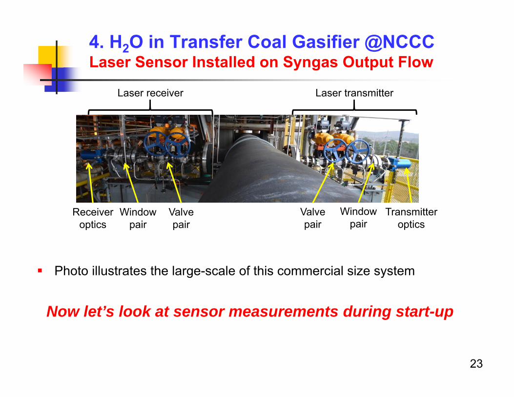
Photo illustrates the large-scale of this commercial size system
Now let’s look at sensor measurements during start-up
4. H2O in Transfer Coal Gasifier @NCCC Laser Sensor Installed on Syngas Output Flow
Transmitter optics
Window pair
Valve pair
Laser receiver Laser transmitter
Receiver optics
Valve pair
Window pair
23
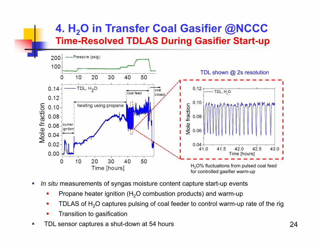
4. H2O in Transfer Coal Gasifier @NCCC Time-Resolved TDLAS During Gasifier Start-up
In situ measurements of syngas moisture content capture start-up events Propane heater ignition (H2O combustion products) and warm-up TDLAS of H2O captures pulsing of coal feeder to control warm-up rate of the rig Transition to gasification
TDL sensor captures a shut-down at 54 hours
TDL shown @ 2s resolution
H2O% fluctuations from pulsed coal feed for controlled gasifier warm-up
24
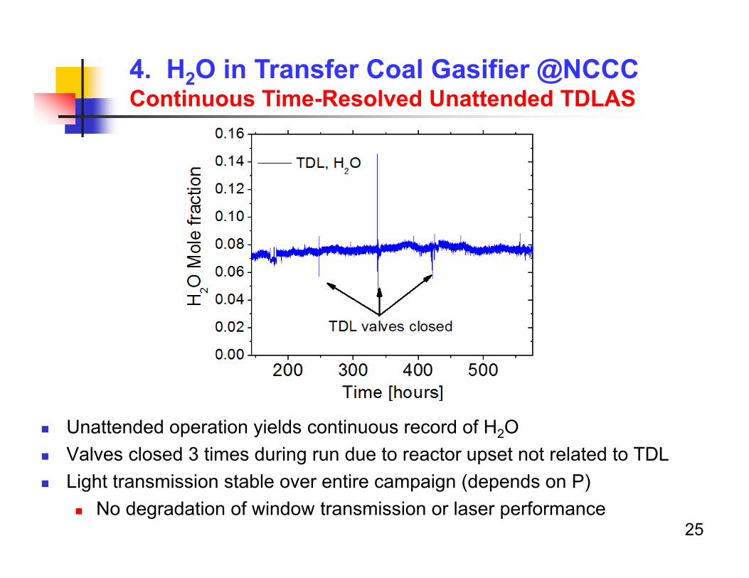
4. H2O in Transfer Coal Gasifier @NCCC Continuous Time-Resolved Unattended TDLAS
25
Unattended operation yields continuous record of H2O Valves closed 3 times during run due to reactor upset not related to TDL Light transmission stable over entire campaign (depends on P)
No degradation of window transmission or laser performance
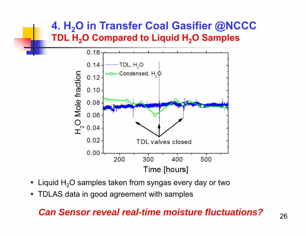
4. H2O in Transfer Coal Gasifier @NCCCTDL H2O Compared to Liquid H2O Samples
Liquid H2O samples taken from syngas every day or two TDLAS data in good agreement with samples
26Can Sensor reveal real-time moisture fluctuations?
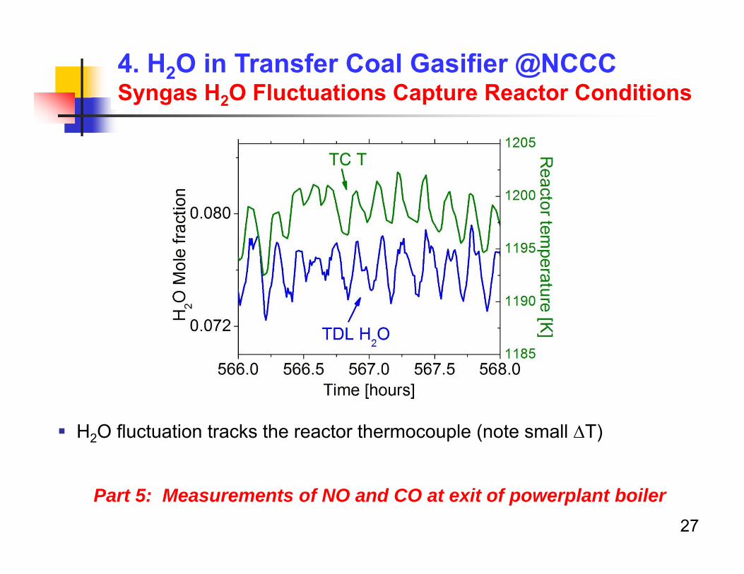
4. H2O in Transfer Coal Gasifier @NCCC Syngas H2O Fluctuations Capture Reactor Conditions
H2O fluctuation tracks the reactor thermocouple (note small T)
27
Part 5: Measurements of NO and CO at exit of powerplant boiler
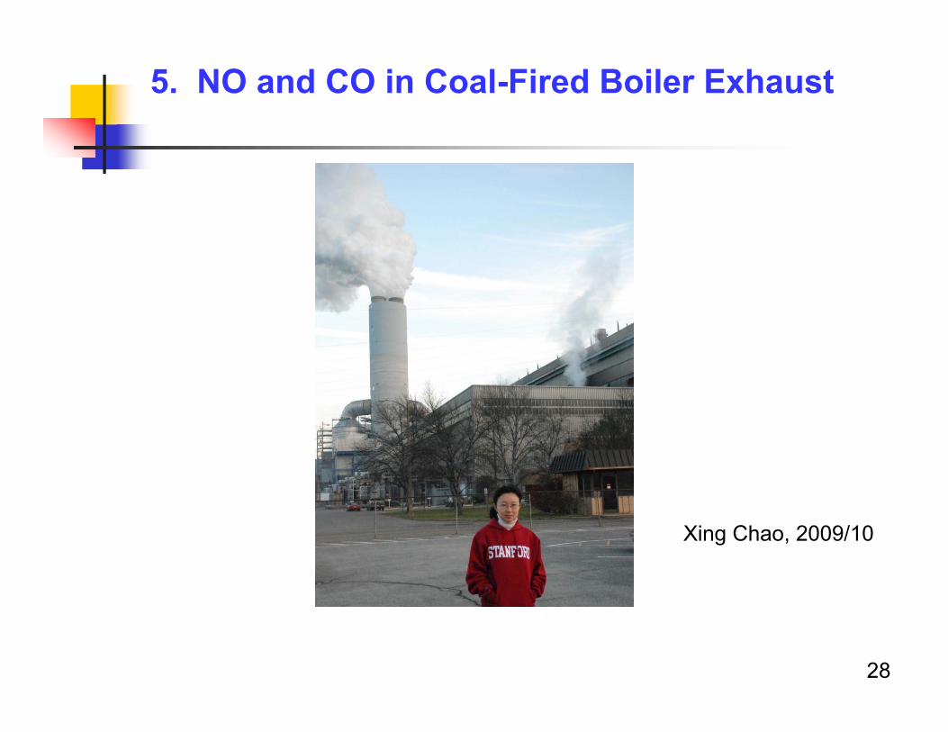
5. NO and CO in Coal-Fired Boiler Exhaust
28
Xing Chao, 2009/10
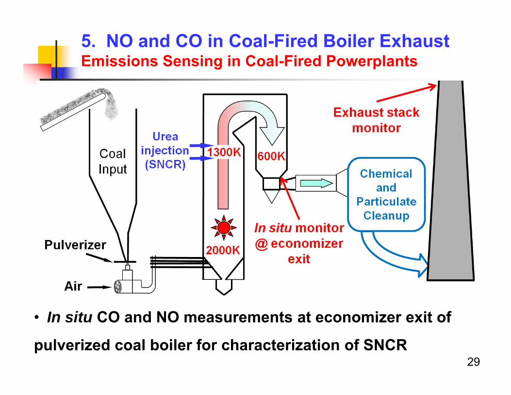
• In situ CO and NO measurements at economizer exit of
pulverized coal boiler for characterization of SNCR
5. NO and CO in Coal-Fired Boiler ExhaustEmissions Sensing in Coal-Fired Powerplants
29
30
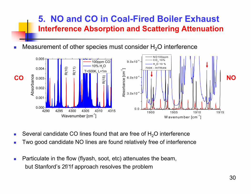
Measurement of other species must consider H2O interference
5. NO and CO in Coal-Fired Boiler Exhaust Interference Absorption and Scattering Attenuation
1900 1905 1910 19150.0
3.0x10 -4
6.0x10 -4
9.0x10 -4
Abso
rban
ce [c
m-1]
W avenum ber [cm -1]
N O 100ppm C O 2 10% H 2O 10 %
700K - H ITR AN
4290 4295 4300 4305 4310 43150.000
0.001
0.002
0.003
0.004
0.005
R(1
5)
R(1
1)
Abso
rban
ce
Wavenumber [cm-1]
100ppm CO 10% H2O
T=500K, L=1mR
(10)
CO NO
Several candidate CO lines found that are free of H2O interference Two good candidate NO lines are found relatively free of interference
Particulate in the flow (flyash, soot, etc) attenuates the beam,but Stanford’s 2f/1f approach resolves the problem
5. NO and CO in Coal-Fired Boiler ExhaustSensing at the Economizer Exit
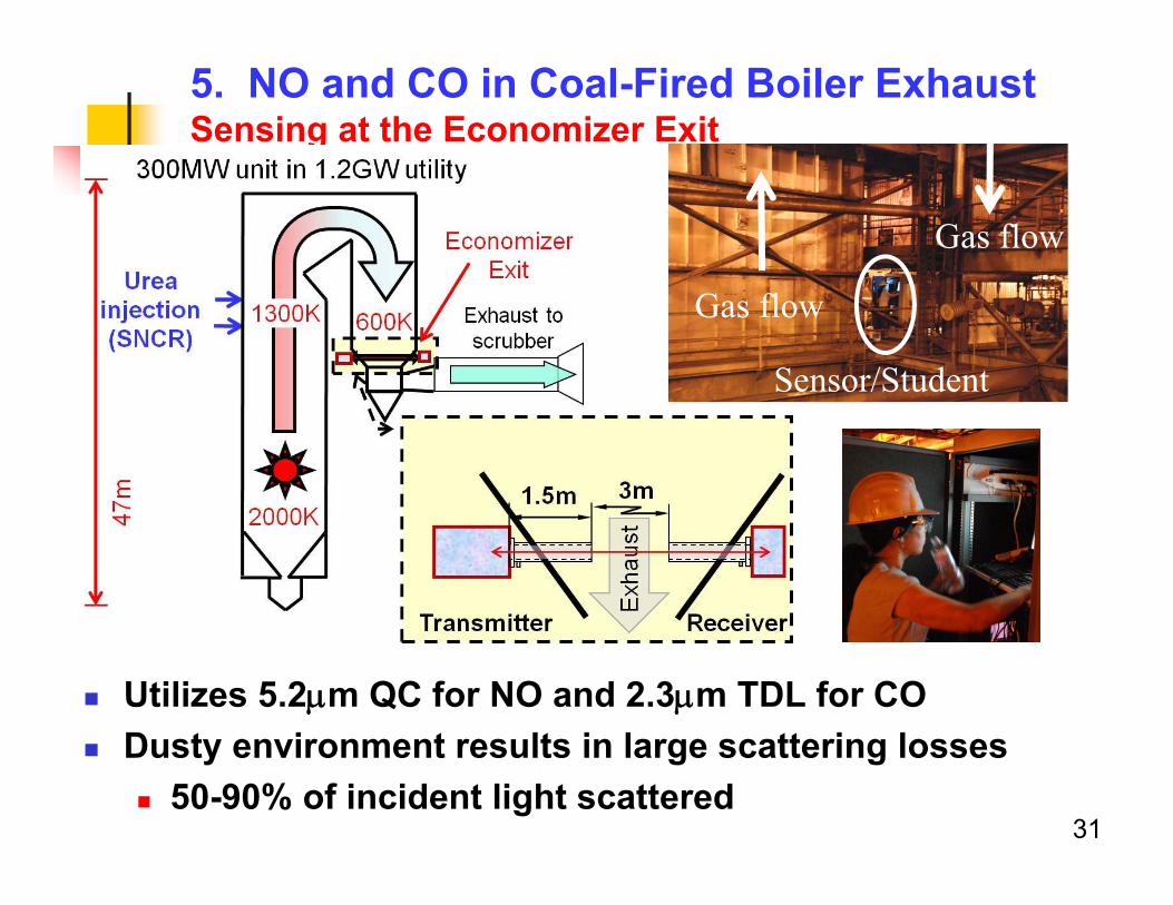
Utilizes 5.2m QC for NO and 2.3m TDL for CO Dusty environment results in large scattering losses
50-90% of incident light scattered
Stanford – EPRI collaboration 2009
Gas flow
Gas flow
Sensor/Student
31
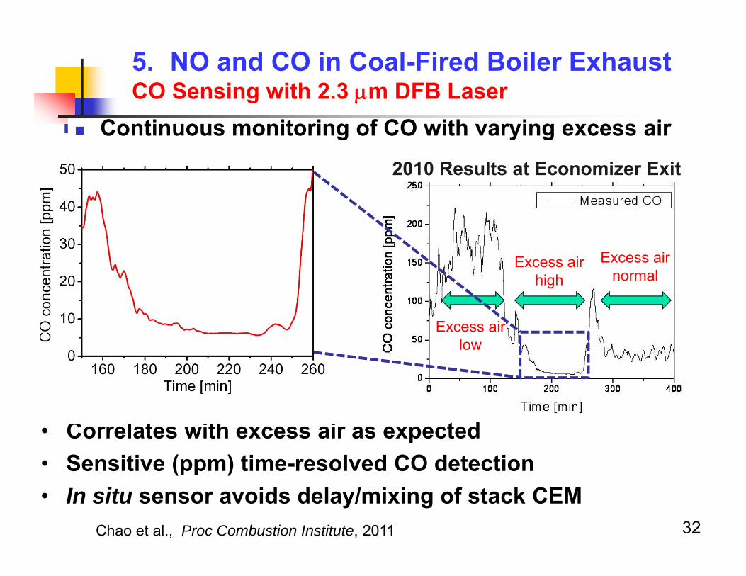
Continuous monitoring of CO with varying excess air
Excess air low
Excess air high
Excess air normal
5. NO and CO in Coal-Fired Boiler ExhaustCO Sensing with 2.3 m DFB Laser
• Correlates with excess air as expected • Sensitive (ppm) time-resolved CO detection• In situ sensor avoids delay/mixing of stack CEM
2010 Results at Economizer Exit
32Chao et al., Proc Combustion Institute, 2011

5. NO and CO in Coal-Fired Boiler ExhaustNO Sensing with 5.2 m QC Laser
Sensitive (ppm) time-resolved NO detection In situ sensor avoids delay/mixing of stack CEM Potential for control of individual boilers
2010 Results at Economizer Exitof Pulverized Coal-Fired Plant
33
6. TDLAS for Energy Conversion – Future Trends
34
Portable TDL-based sensors useful for T, V, species and mass flux over wide range of conditions, industries
Potential use as control variables for combustion emissions/efficiency Potential use for compliance monitoring of pollutant emissions
Current and future topics: Extension to UV and mid-IR to access new species
CO, CO2, HC’s, radicals, NO, NO2
Advanced energy utilization: bio-fuels, gasification, liquifying natural gas
Next Lecture
Shock tubes and applications to combustion kinetics
35