Embed Size (px)
DESCRIPTION
merox
Citation preview
04
/21
/20
23
1
LECTURE–10: CLOUS PROCESSMEROX PROCESSES
CHEMICAL TECHNOLOGY (CH-206)
Dr. Vimal KumarDepartment of Chemical Engineering
04
/21
/20
23
2
CLAUS PROCESS The Claus process is used to convert gaseous
hydrogen sulfide (H2S) into elemental sulfur (S) in the presence of a catalyst.
Generally, it is also referred as sulfur recovery unit (SRU).
It is widely used to produce elemental sulfur from H2S from: raw natural gas, and the by-product sour gases containing hydrogen
sulfide derived from refining petroleum crude oil and other industrial facilities.
In 2010, the world wide production of by-product sulfur was 68 M metric tons, majorly from petroleum refining and natural gas processing plants.
04
/21
/20
23
3
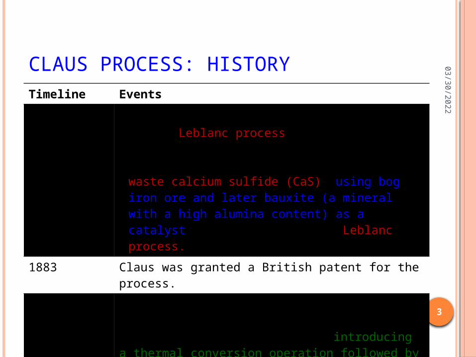
CLAUS PROCESS: HISTORYTimeline Events
19th century • The sodium carbonate (Na2CO3) was produced by the Leblanc process.
• Carl Friedrich Claus, a chemist working in England, recovered sulfur from the waste calcium sulfide (CaS), using bog iron ore and later bauxite (a mineral with a high alumina content) as a catalyst, a by–product of the Leblanc process.
1883 Claus was granted a British patent for the process.
1936 I.G. Farbenindustrie a (German conglomerate of chemical companies) modified the Claus process by introducing a thermal conversion operation followed by catalytic conversion process, which is the concept used in modern Claus sulfur recovery units.
04
/21
/20
23
4
CLAUS PROCESS: H2S SOURCES
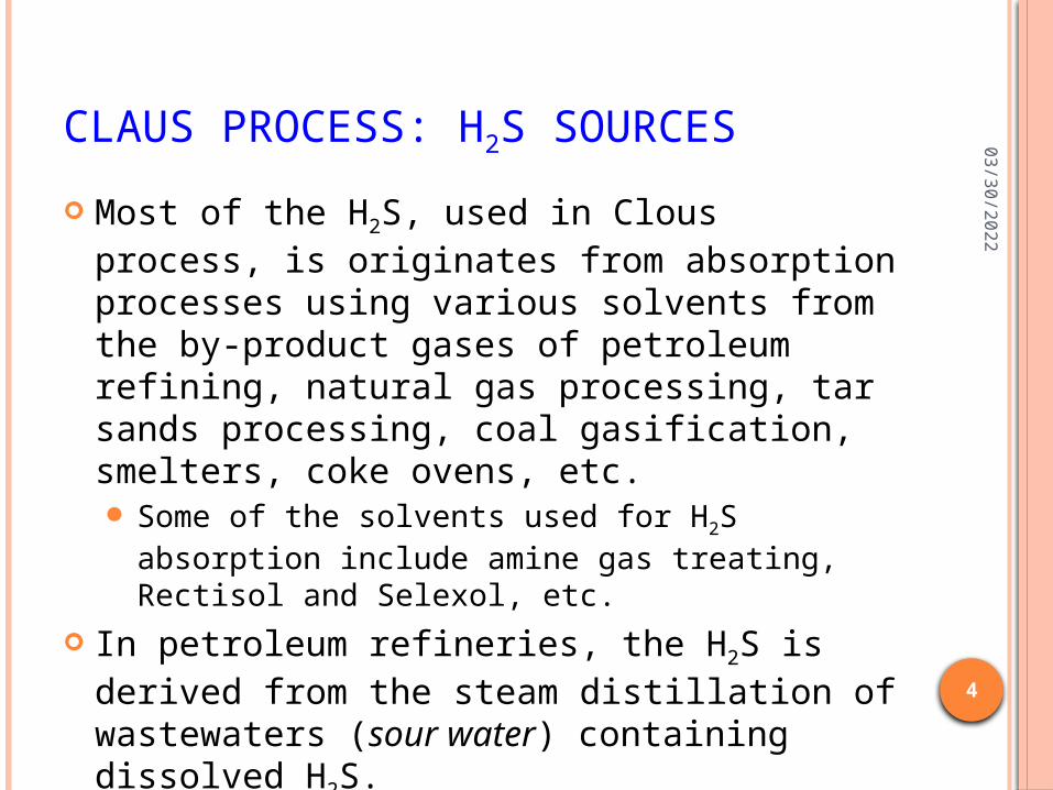
Most of the H2S, used in Clous process, is originates from absorption processes using various solvents from the by-product gases of petroleum refining, natural gas processing, tar sands processing, coal gasification, smelters, coke ovens, etc. Some of the solvents used for H2S absorption
include amine gas treating, Rectisol and Selexol, etc.
In petroleum refineries, the H2S is derived from the steam distillation of wastewaters (sour water) containing dissolved H2S.
04
/21
/20
23
5
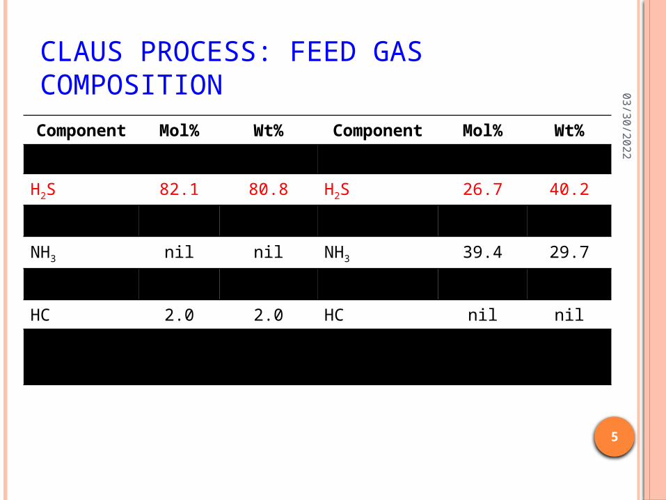
CLAUS PROCESS: FEED GAS COMPOSITION
Component
Mol% Wt% Component
Mol% Wt%
From an amine process From a sour water stripper
H2S 82.1 80.8 H2S 26.7 40.2
CO2 11.9 15.1 CO2 2.6 5.1
NH3 nil nil NH3 39.4 29.7
H2O 4.0 2.1 H2O 31.3 25.0
HC 2.0 2.0 HC nil nil
Notes: H2S is hydrogen sulfide, CO2 is carbon dioxide, NH3 is ammonia, H2O is water and HC is hydrocarbons.
04
/21
/20
23
6
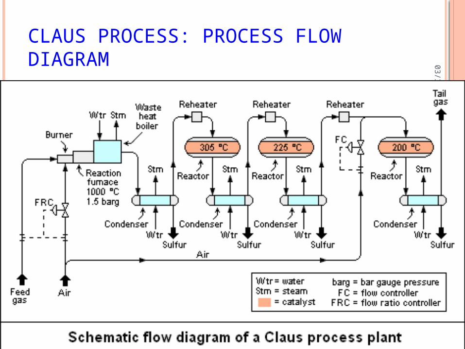
CLAUS PROCESS: PROCESS FLOW DIAGRAM
04
/21
/20
23
7
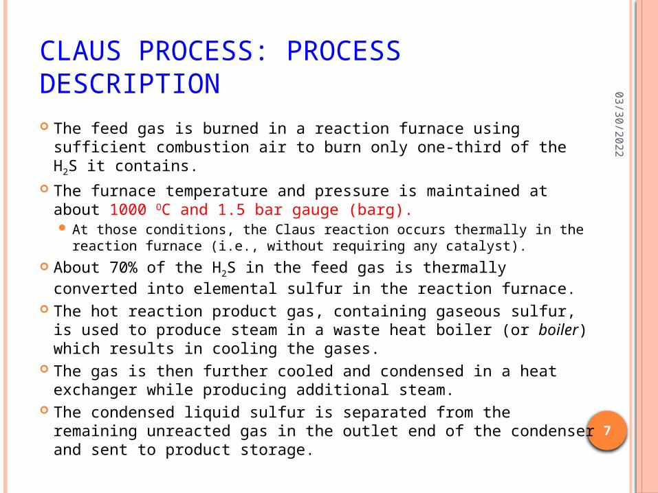
CLAUS PROCESS: PROCESS DESCRIPTION The feed gas is burned in a reaction furnace using sufficient
combustion air to burn only one-third of the H2S it contains. The furnace temperature and pressure is maintained at about
1000 OC and 1.5 bar gauge (barg). At those conditions, the Claus reaction occurs thermally in the
reaction furnace (i.e., without requiring any catalyst). About 70% of the H2S in the feed gas is thermally converted
into elemental sulfur in the reaction furnace. The hot reaction product gas, containing gaseous sulfur, is used
to produce steam in a waste heat boiler (or boiler) which results in cooling the gases.
The gas is then further cooled and condensed in a heat exchanger while producing additional steam.
The condensed liquid sulfur is separated from the remaining unreacted gas in the outlet end of the condenser and sent to product storage.
04
/21
/20
23
8
CLAUS PROCESS: PROCESS DESCRIPTION
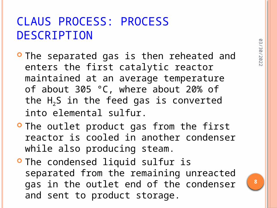
The separated gas is then reheated and enters the first catalytic reactor maintained at an average temperature of about 305 °C, where about 20% of the H2S in the feed gas is converted into elemental sulfur.
The outlet product gas from the first reactor is cooled in another condenser while also producing steam.
The condensed liquid sulfur is separated from the remaining unreacted gas in the outlet end of the condenser and sent to product storage.
04
/21
/20
23
9
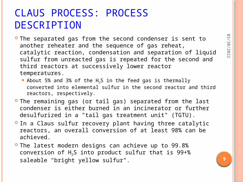
CLAUS PROCESS: PROCESS DESCRIPTION The separated gas from the second condenser is sent to
another reheater and the sequence of gas reheat, catalytic reaction, condensation and separation of liquid sulfur from unreacted gas is repeated for the second and third reactors at successively lower reactor temperatures. About 5% and 3% of the H2S in the feed gas is thermally converted
into elemental sulfur in the second reactor and third reactors, respectively.
The remaining gas (or tail gas) separated from the last condenser is either burned in an incinerator or further desulfurized in a "tail gas treatment unit" (TGTU).
In a Claus sulfur recovery plant having three catalytic reactors, an overall conversion of at least 98% can be achieved.
The latest modern designs can achieve up to 99.8% conversion of H2S into product sulfur that is 99+% saleable "bright yellow sulfur".
04
/21
/20
23
10
CLAUS PROCESS: REHEAT METHODS
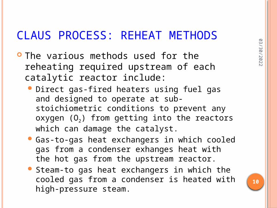
The various methods used for the reheating required upstream of each catalytic reactor include: Direct gas-fired heaters using fuel gas and
designed to operate at sub-stoichiometric conditions to prevent any oxygen (O2) from getting into the reactors which can damage the catalyst.
Gas-to-gas heat exchangers in which cooled gas from a condenser exhanges heat with the hot gas from the upstream reactor.
Steam-to gas heat exchangers in which the cooled gas from a condenser is heated with high-pressure steam.
04
/21
/20
23
11
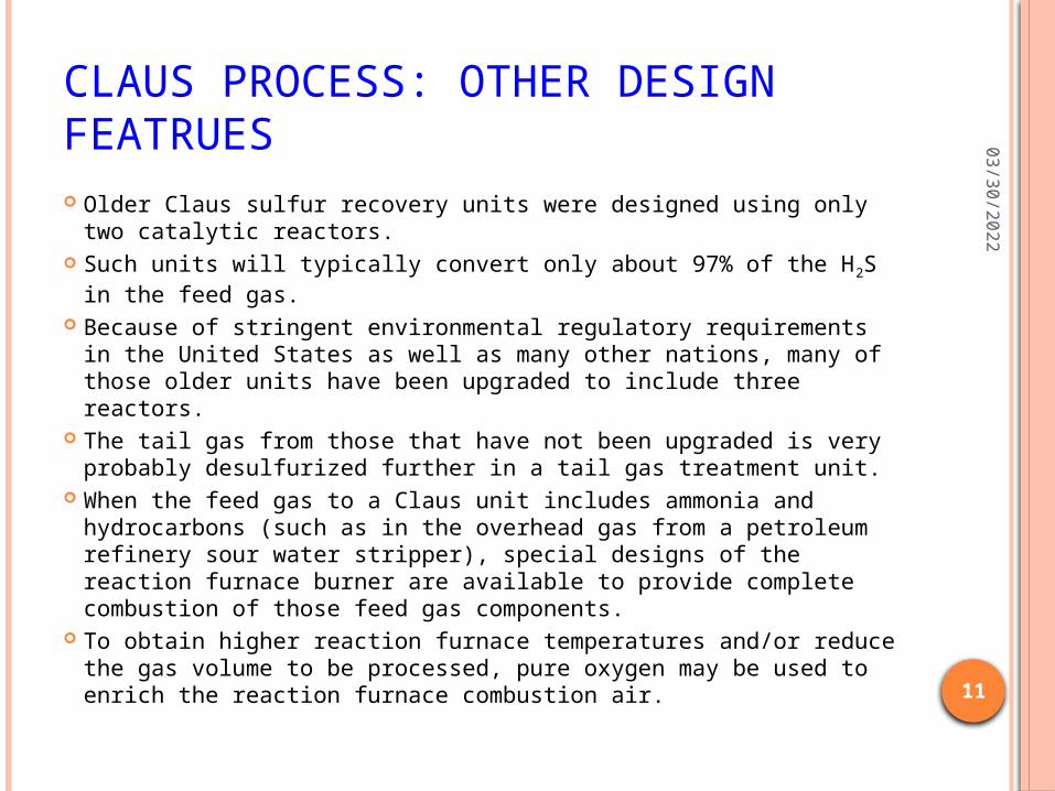
CLAUS PROCESS: OTHER DESIGN FEATRUES Older Claus sulfur recovery units were designed using only two
catalytic reactors. Such units will typically convert only about 97% of the H2S in the
feed gas. Because of stringent environmental regulatory requirements in
the United States as well as many other nations, many of those older units have been upgraded to include three reactors.
The tail gas from those that have not been upgraded is very probably desulfurized further in a tail gas treatment unit.
When the feed gas to a Claus unit includes ammonia and hydrocarbons (such as in the overhead gas from a petroleum refinery sour water stripper), special designs of the reaction furnace burner are available to provide complete combustion of those feed gas components.
To obtain higher reaction furnace temperatures and/or reduce the gas volume to be processed, pure oxygen may be used to enrich the reaction furnace combustion air.
04
/21
/20
23
12
CLAUS PROCESS: REACTION MECHANISM
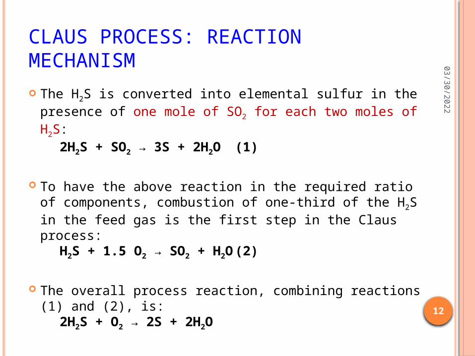
The H2S is converted into elemental sulfur in the presence of one mole of SO2 for each two moles of H2S:
2H2S + SO2 → 3S + 2H2O (1)
To have the above reaction in the required ratio of components, combustion of one-third of the H2S in the feed gas is the first step in the Claus process:
H2S + 1.5 O2 → SO2 + H2O (2)
The overall process reaction, combining reactions (1) and (2), is:
2H2S + O2 → 2S + 2H2O
04
/21
/20
23
13
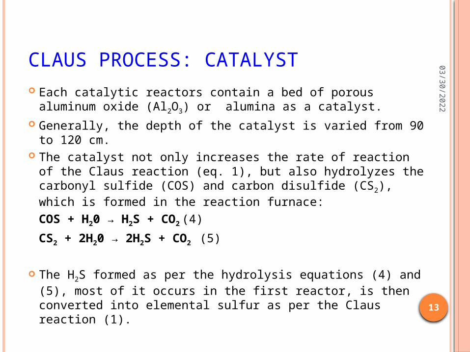
CLAUS PROCESS: CATALYST Each catalytic reactors contain a bed of porous aluminum
oxide (Al2O3) or alumina as a catalyst. Generally, the depth of the catalyst is varied from 90 to
120 cm. The catalyst not only increases the rate of reaction of the
Claus reaction (eq. 1), but also hydrolyzes the carbonyl sulfide (COS) and carbon disulfide (CS2), which is formed in the reaction furnace:
COS + H20 → H2S + CO2 (4)
CS2 + 2H20 → 2H2S + CO2 (5)
The H2S formed as per the hydrolysis equations (4) and (5), most of it occurs in the first reactor, is then converted into elemental sulfur as per the Claus reaction (1).
04
/21
/20
23
14
CLAUS PROCESS: CATALYST
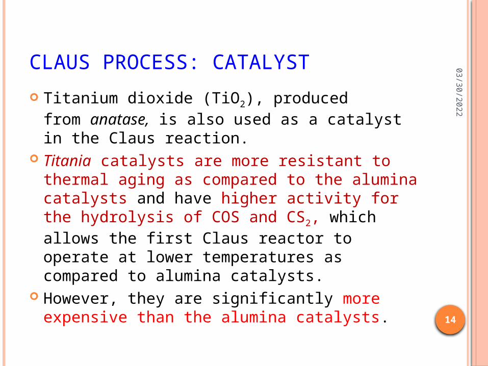
Titanium dioxide (TiO2), produced from anatase, is also used as a catalyst in the Claus reaction.
Titania catalysts are more resistant to thermal aging as compared to the alumina catalysts and have higher activity for the hydrolysis of COS and CS2, which allows the first Claus reactor to operate at lower temperatures as compared to alumina catalysts.
However, they are significantly more expensive than the alumina catalysts.
04
/21
/20
23
15
MEROX (MERCAPTON OXIDATION) PROCESSMerox Extraction
Merox Sweetening
04
/21
/20
23
16
MEROX (MERCAPTON OXIDATION) PROCESS
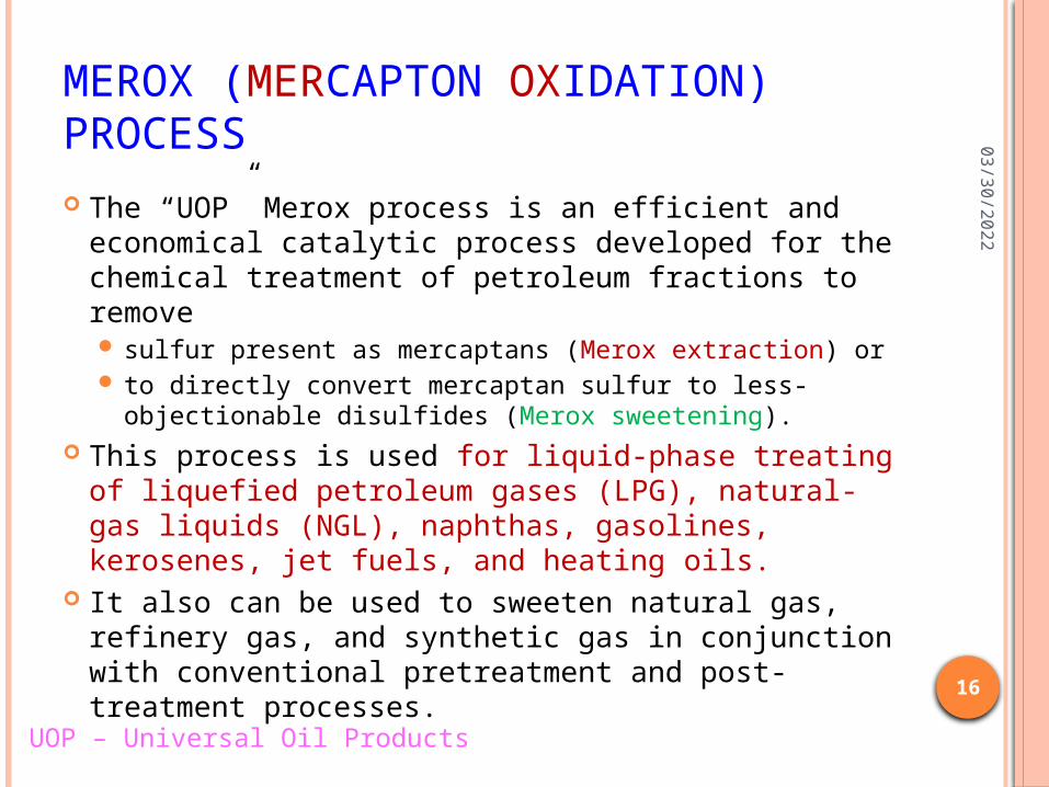
The “UOP” Merox process is an efficient and economical catalytic process developed for the chemical treatment of petroleum fractions to remove sulfur present as mercaptans (Merox extraction) or to directly convert mercaptan sulfur to less-
objectionable disulfides (Merox sweetening). This process is used for liquid-phase treating of
liquefied petroleum gases (LPG), natural-gas liquids (NGL), naphthas, gasolines, kerosenes, jet fuels, and heating oils.
It also can be used to sweeten natural gas, refinery gas, and synthetic gas in conjunction with conventional pretreatment and post-treatment processes.UOP – Universal Oil Products
04
/21
/20
23
17
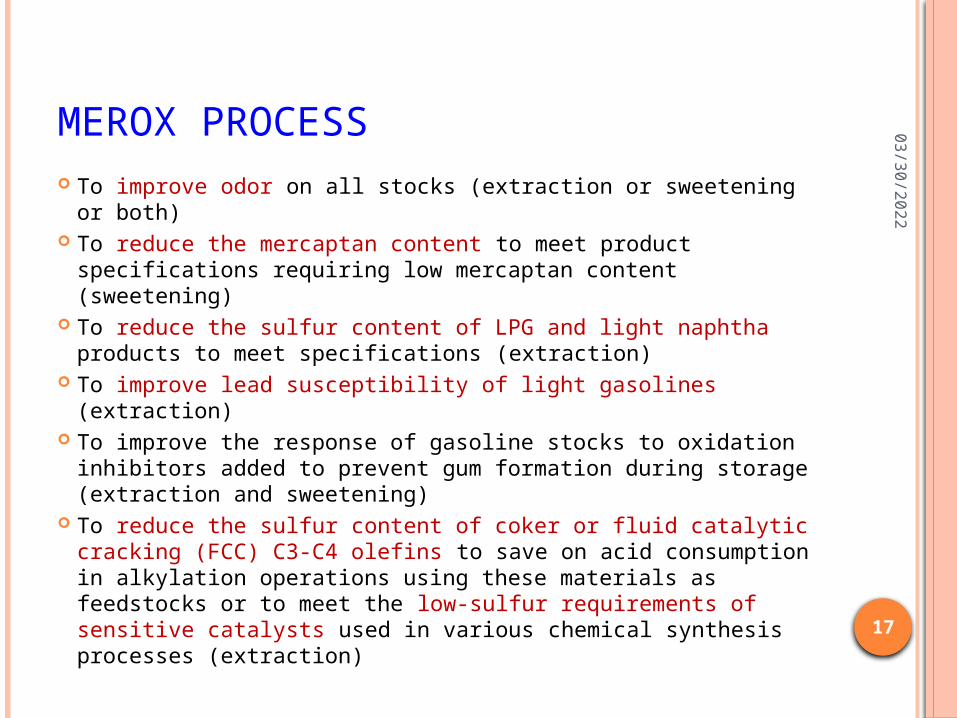
MEROX PROCESS To improve odor on all stocks (extraction or sweetening or
both) To reduce the mercaptan content to meet product
specifications requiring low mercaptan content (sweetening) To reduce the sulfur content of LPG and light naphtha
products to meet specifications (extraction) To improve lead susceptibility of light gasolines (extraction) To improve the response of gasoline stocks to oxidation
inhibitors added to prevent gum formation during storage (extraction and sweetening)
To reduce the sulfur content of coker or fluid catalytic cracking (FCC) C3-C4 olefins to save on acid consumption in alkylation operations using these materials as feedstocks or to meet the low-sulfur requirements of sensitive catalysts used in various chemical synthesis processes (extraction)
04
/21
/20
23
18
MEROX PROCESS
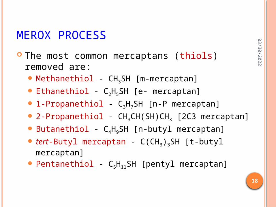
The most common mercaptans (thiols) removed are: Methanethiol - CH3SH [m-mercaptan] Ethanethiol - C2H5SH [e- mercaptan] 1-Propanethiol - C3H7SH [n-P mercaptan] 2-Propanethiol - CH3CH(SH)CH3 [2C3 mercaptan] Butanethiol - C4H9SH [n-butyl mercaptan] tert-Butyl mercaptan - C(CH3)3SH [t-butyl mercaptan] Pentanethiol - C5H11SH [pentyl mercaptan]
04
/21
/20
23
19
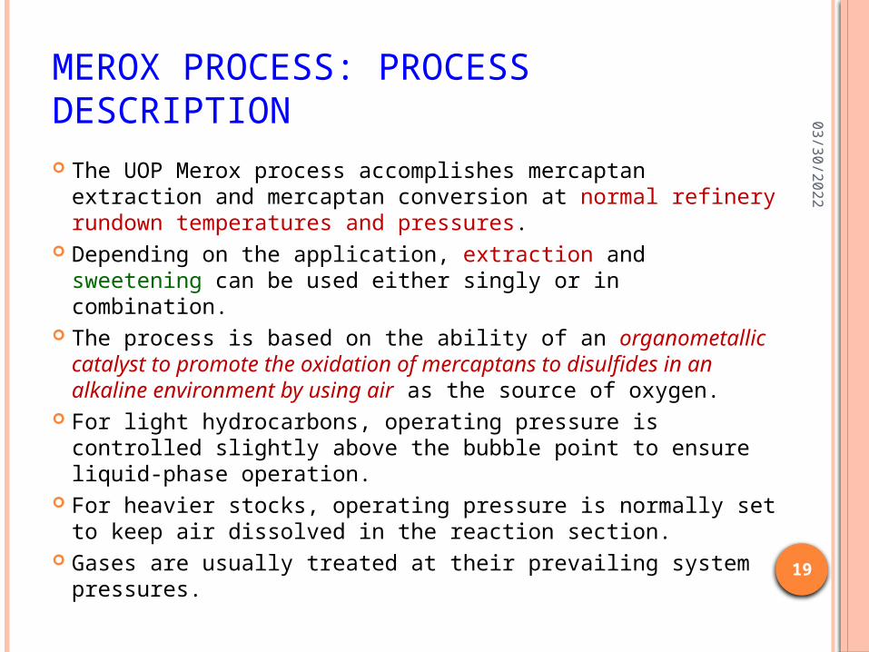
MEROX PROCESS: PROCESS DESCRIPTION The UOP Merox process accomplishes mercaptan extraction
and mercaptan conversion at normal refinery rundown temperatures and pressures.
Depending on the application, extraction and sweetening can be used either singly or in combination.
The process is based on the ability of an organometallic catalyst to promote the oxidation of mercaptans to disulfides in an alkaline environment by using air as the source of oxygen.
For light hydrocarbons, operating pressure is controlled slightly above the bubble point to ensure liquid-phase operation.
For heavier stocks, operating pressure is normally set to keep air dissolved in the reaction section.
Gases are usually treated at their prevailing system pressures.
04
/21
/20
23
20
MEROX PROCESS: EXTRACTION
Low-molecular-weight mercaptans are soluble in caustic soda solution.
Therefore, for LPG, or light-gasoline fractions, the Merox process can be used to extract mercaptans.
In the extraction unit, the sulfur reduction attainable is directly related to the extractable-mercaptan content of the fresh feed.
In mercaptan-extraction units, fresh feed is charged to an extraction column, where mercaptans are extracted by a counter-current caustic stream.
The treated product passes overhead to storage or downstream processing.
04
/21
/20
23
21
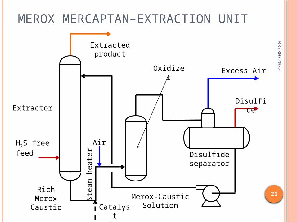
MEROX MERCAPTAN–EXTRACTION UNIT
Extractor
H2S free feed
Extracted product
Air
Catalyst Injection
Rich Merox Caustic
Oxidizer
Merox-Caustic Solution
Disulfide separator
Disulfide
Excess Air
Ste
am
heate
r
04
/21
/20
23
22
MEROX EXTRACTION The mercaptan-rich caustic solution containing Merox
catalyst flows from the bottom of the extraction column to the regeneration section through a steam heater, which is used to maintain a suitable temperature in the oxidizer.
Air is injected into this stream, and the mixture flows upward through the oxidizer, where the caustic is regenerated by converting mercaptans to disulfides.
The oxidizer effluent flows into the disulfide separator, where spent air, disulfide oil, and the regenerated caustic solution are separated.
Spent air is vented to a safe place, and disulfide oil is decanted and sent to appropriate disposal (may be hydrotreating unit).
The regenerated-caustic stream is returned to the extraction column.
A small amount of Merox catalyst is added periodically to maintain the required activity.
04
/21
/20
23
23
MEROX PROCESS: SWEETENING
In sweetening units, the mercaptans are converted directly to disulfides, which remain in the product; the total sulfur content of the treated stock is not reduced.
Merox sweetening can be accomplished in four ways: Fixed-bed processing with intermittent circulation
of caustic solution Minimum-alkali fixed-bed (Minalk*) processing,
which uses small amounts of caustic solution injected continuously
Caustic-Free Merox* treatment for gasoline and kerosene
Liquid-liquid sweetening
04
/21
/20
23
24
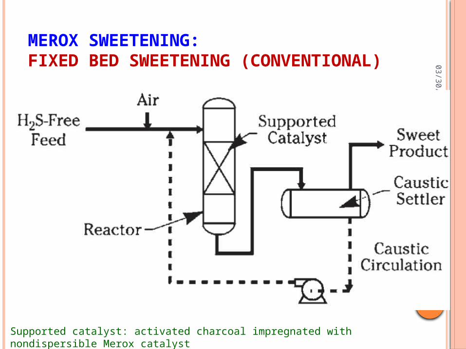
MEROX SWEETENING: FIXED BED SWEETENING (CONVENTIONAL)
Supported catalyst: activated charcoal impregnated with nondispersible Merox catalyst
04
/21
/20
23
25
MEROX SWEETENING: FIXED BED SWEETENING (CONVENTIONAL)
Fixed-bed sweetening is normally employed for raw or thermally cracked chargestocks having endpoints above about 120°C. The higher-molecular-weight and more branched mercaptan
types associated with these higher-endpoint feedstocks are only slightly soluble in caustic solution and are more difficult to sweeten.
The use of a fixed-bed reactor facilitates the conversion of these types of mercaptans to disulfides.
In fixed-bed sweetening unit a reactor contains a bed of specially selected activated charcoal impregnated with nondispersible Merox catalyst and wetted with caustic solution.
Air is injected into the feed hydrocarbon steam ahead of the reactor, and in passed through the catalyst bed, the mercaptans in the feed are oxidized to disulfides.
04
/21
/20
23
26
MEROX SWEETENING: FIXED BED SWEETENING (CONVENTIONAL)
The reactor is followed by a settler for separation of caustic and treated hydrocarbon. The settler also serves as a caustic reservoir.
Separated caustic is circulated intermittently to keep the catalyst bed wet.
The frequency of caustic circulation over the bed depends on the difficulty of the feedstock being treated and the activity of the catalyst.
The fixed-bed Merox sweetening is used in the production of jet fuels and kerosenes.
As a result of the development of the Merox fixed-bed system, jet fuels and kerosenes (also diesel and heating oils) can be sweetened at costs that are incomparably lower than those of the simplest hydrotreater.
However, because of other particular jet-fuel quality requirements, some pretreatment and post-treatment are needed whenever any chemical sweetening process is used.
04
/21
/20
23
27
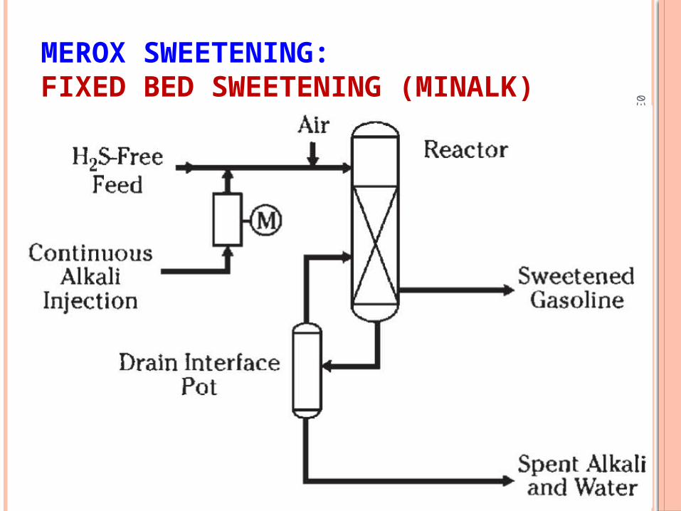
MEROX SWEETENING: FIXED BED SWEETENING (MINALK)
04
/21
/20
23
28
MEROX SWEETENING: FIXED BED SWEETENING (MINALK) The UOP Merox Minalk is applied to feedstocks that are
relatively easy to sweeten, such as catalytically cracked naphthas and light raw naphthas.
This sweetening design achieves the same high efficiency as conventional fixed-bed sweetening but with less equipment and lower capital and operating costs.
The process relies on a small, controlled, continuous injection of an appropriately weak alkali solution rather than the gross, intermittent alkali saturation of the catalyst bed as in conventional fixed-bed Merox sweetening.
This small injection of alkali provides the needed alkalinity so that mercaptans are oxidized to disulfides and do not enter into peroxidation reaction, which would result if the alkalinity were insufficient.
04
/21
/20
23
29
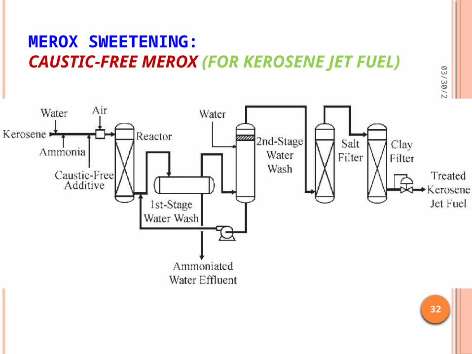
MEROX SWEETENING: CAUSTIC-FREE MEROX The Caustic-Free Merox process is used for sweetening
gasoline and kerosene. The process uses the same basic principles of sweetening in
which the mercaptans are catalytically converted to disulfides, which remain in the treated hydrocarbon product.
The Caustic-Free Merox catalyst system consists of preimpregnated fixed-bed catalysts, Merox No. 21 catalyst for gasoline and Merox No. 31 catalyst for kerosene, and a liquid activator, Merox CF.
This system provides an active, selective, and stable sweetening environment in the reactor.
The high activity allows the use of a weak base, ammonia, to provide the needed reaction alkalinity.
No caustic (NaOH) is required, and fresh-caustic costs and the costs for handling and disposing of spent caustic are thus eliminated.
04
/21
/20
23
30
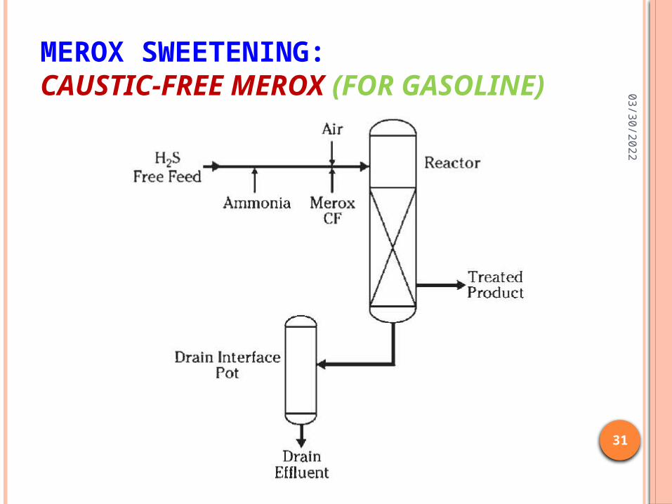
MEROX SWEETENING: CAUSTIC-FREE MEROX The actual design of the Caustic-Free Merox unit
depends on whether it is used on gasoline or kerosene. The reactor section is similar to the fixed-bed systems,
conventional and Minalk, except for the substitution of a different catalyst, the addition of facilities for continuous injection of the Merox CF activator, and replacement of the caustic injection facilities with ammonia injection facilities, anhydrous or aqueous.
For kerosene or jet fuel production, the downstream water-wash system is modified to improve efficiency and to ensure that no ammonia remains in the finished product.
Other post-treatment facilities for jet fuel production remain unchanged.
04
/21
/20
23
31
MEROX SWEETENING: CAUSTIC-FREE MEROX (FOR GASOLINE)
04
/21
/20
23
32
MEROX SWEETENING: CAUSTIC-FREE MEROX (FOR KEROSENE JET FUEL)
04
/21
/20
23
33
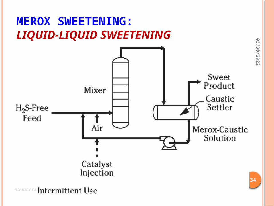
MEROX SWEETENING: LIQUID-LIQUID SWEETENING The liquid-liquid sweetening version of the Merox process is not in use
nowadays as refiners has switched to the new units as they are having more active fixed-bed systems.
Hydrocarbon feed, air, and aqueous caustic soda containing dispersed Merox catalyst are simultaneously contacted in a mixing device, where mercaptans are converted to disulfides.
Mixer effluent is directed to a settler, from which the treated hydrocarbon stream is sent to storage or further processing.
Separated caustic solution from the settler is recirculated to the mixer. A small amount of Merox catalyst is added periodically to maintain the
catalytic activity. The liquid-liquid sweetening is applicable to raw light, thermally
cracked gasolines and to components having endpoints up to about 120°C.
The mercaptan types associated with catalytically cracked naphthas are easier to oxidize than those contained in light raw or thermal naphthas, and therefore liquid-liquid sweetening has been successfully applied to catalytically cracked gasolines having endpoints as high as 230°C.
04
/21
/20
23
34
MEROX SWEETENING: LIQUID-LIQUID SWEETENING
04
/21
/20
23
35
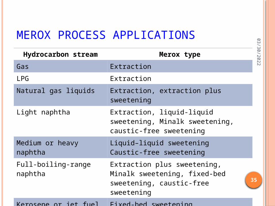
MEROX PROCESS APPLICATIONS
Hydrocarbon stream Merox type
Gas Extraction
LPG Extraction
Natural gas liquids Extraction, extraction plus sweetening
Light naphtha Extraction, liquid-liquid sweetening, Minalk sweetening, caustic-free sweetening
Medium or heavy naphtha
Liquid–liquid sweeteningCaustic-free sweetening
Full-boiling-range naphtha
Extraction plus sweetening, Minalk sweetening, fixed-bed sweetening, caustic-free sweetening
Kerosene or jet fuel Fixed-bed sweeteningCaustic-free sweetening
Diesel Fixed-bed sweetening
04
/21
/20
23
36
PROCESS CHEMISTRY
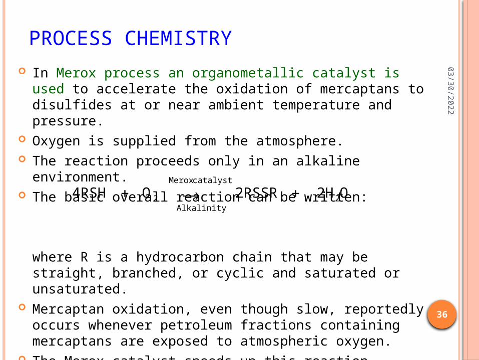
In Merox process an organometallic catalyst is used to accelerate the oxidation of mercaptans to disulfides at or near ambient temperature and pressure.
Oxygen is supplied from the atmosphere. The reaction proceeds only in an alkaline environment. The basic overall reaction can be written:
where R is a hydrocarbon chain that may be straight, branched, or cyclic and saturated or unsaturated.
Mercaptan oxidation, even though slow, reportedly occurs whenever petroleum fractions containing mercaptans are exposed to atmospheric oxygen.
The Merox catalyst speeds up this reaction, directs the products to disulfides, and minimizes undesirable side reactions.
O2H 2RSSR O 4RSH 2
catalystMerox
Alkalinity2

04
/21
/20
23
37
PROCESS CHEMISTRYMEROX EXTRACTION In Merox extraction, in which mercaptans in the liquid
or gaseous feedstocks are highly soluble in the caustic soda solution as solvent, the mercaptan oxidation is done outside the extraction environment.
Therefore, a mercaptan-extraction step is followed by oxidation of the extracted mercaptan as follows:
According to these treating steps, the treated product has reduced sulfur content corresponding to the amount of mercaptan extracted.
)(insoluble phase Oilphase Aquesous
catalystMerox
22
2phase Aquesousphase Aquesousphase Oil
2RSSR 4NaOH O2H O 4NaSR
OH NaSR NaOH RSH
04
/21
/20
23
38
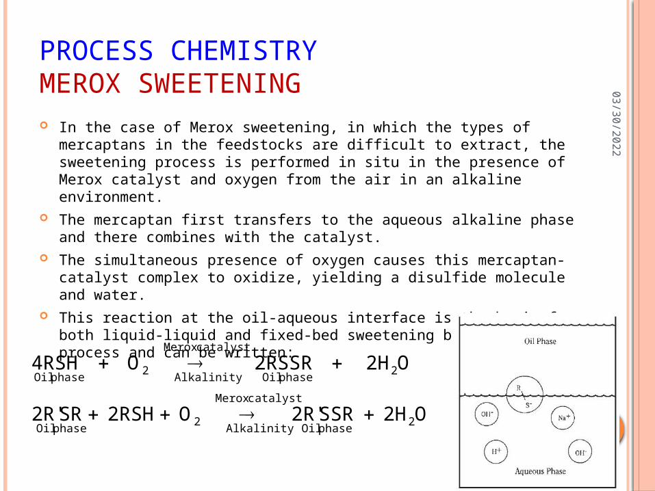
PROCESS CHEMISTRYMEROX SWEETENING In the case of Merox sweetening, in which the types of mercaptans in
the feedstocks are difficult to extract, the sweetening process is performed in situ in the presence of Merox catalyst and oxygen from the air in an alkaline environment.
The mercaptan first transfers to the aqueous alkaline phase and there combines with the catalyst.
The simultaneous presence of oxygen causes this mercaptan-catalyst complex to oxidize, yielding a disulfide molecule and water.
This reaction at the oil-aqueous interface is the basis for both liquid-liquid and fixed-bed sweetening by the Merox process and can be written:
O2H SSR2R' O 2RSH SR2R'
O2H 2RSSR O 4RSH
2phase Oil
catalystMerox
Alkalinity2
phase Oil
2phase Oil
catalystMerox
Alkalinity2
phase Oil
04
/21
/20
23
39
MEROX PROCESS FEATURES
Low Operating Cost and Investment Requirement
Ease of Operation Proven Reliability Minimal Chemical-Disposal Requirements Proven Ability to Produce Specification
Products High-Efficiency Design High-Activity Catalyst and Activators
04
/21
/20
23
40
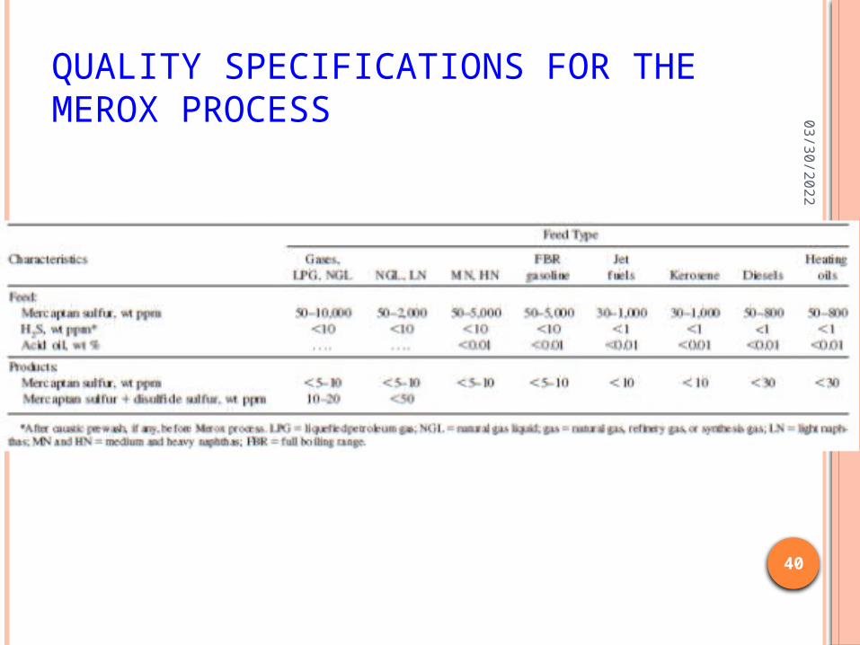
QUALITY SPECIFICATIONS FOR THE MEROX PROCESS
04
/21
/20
23
41
PROCESS STATUS AND OUTLOOK
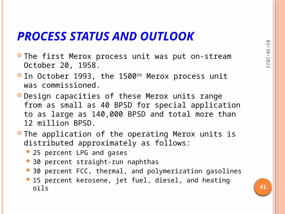
The first Merox process unit was put on-stream October 20, 1958.
In October 1993, the 1500th Merox process unit was commissioned.
Design capacities of these Merox units range from as small as 40 BPSD for special application to as large as 140,000 BPSD and total more than 12 million BPSD.
The application of the operating Merox units is distributed approximately as follows: 25 percent LPG and gases 30 percent straight-run naphthas 30 percent FCC, thermal, and polymerization gasolines 15 percent kerosene, jet fuel, diesel, and heating oils
04
/21
/20
23
42
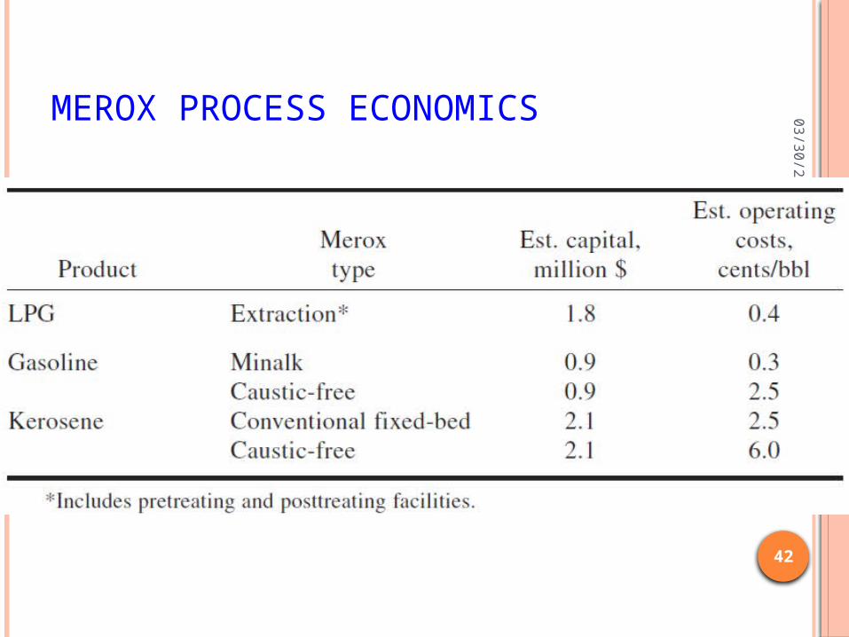
MEROX PROCESS ECONOMICS
04
/21
/20
23
43
CLAUS PROCESS: REFERENCES J.H. Gary and G.E. Handwerk(1984), Petroleum Refining Technology
and Economics, 2nd Edition, Marcel Dekker, ISBN 0-8247-7150-8. Fundamental and Practical Aspects of the Claus Sulfur Recovery Proce
ss P.D. Clark, N.I. Dowling and M. Huang, Alberta Sulfur Research Ltd., Calgary, Alberta, Canada
The SuperClaus process Sulfur production report by the United States Geological Survey Gas Processors Suppliers Association(GPSA) (1987), Gas Processors
Suppliers Association Engineering Data Book, 10th Edition, Gas Processors Suppliers Association. (See Volume II, Section 22)
The Role of Claus Catalyst in Sulfur Recovery Unit Performance Terry McHugh, Ed Luinstra and Peter Clark,presented at Sulphur 98 conference in Tucson, Arizona, November 1998.
Arthur Kohl and Richard Nielson (1997), Gas Purification, 5th Edition, Gulf Professional Publishing, ISBN 0-88415-220-0.
Howard F. Rase (2000), Handbook of Commercial Catalysts:Heterogeneous Catalysts, 1st Edition, CRC Press, pp. 240 - 242, ISBN 0-8493-9417-1.
British patent 5,958 (1883)