Embed Size (px)
Citation preview

1
Lec 28: Conclusions
Kavita BalaCS 3410, Fall 2008Computer ScienceCornell University
© Kavita Bala, Computer Science, Cornell University
Announcements
• Pizza party was fun– Winner: Andrew Cameron and Ross Anderson
• Final project out tomorrow afternoon– Demos: Dec 16 (Tuesday)
• Prelim 2: Dec 4 Thursday– Hollister 110, 7:30-10:00

2
© Kavita Bala, Computer Science, Cornell University
Prelim 2 Topics• Cumulative, but newer stuff:
– Physical and virtual memory, page tables, TLBs– Caches, cache-conscious programming, caching
issues– Privilege levels, syscalls, traps, interrupts, exceptions– Busses, programmed I/O, memory-mapped I/O– DMA, disks– Synchronization– Multicore processors
© Kavita Bala, Computer Science, Cornell University
Goals• Concurrency poses challenges for:• Correctness
– Threads accessing shared memory should not interfere with each other
• Liveness– Threads should not get stuck, should make forward
progress• Efficiency
– Program should make good use of available computing resources (e.g., processors).
• Fairness– Resources apportioned fairly between threads

3
© Kavita Bala, Computer Science, Cornell University
Race conditions• Def: timing-dependent error involving access to
shared state – Whether it happens depends on how threads
scheduled: who wins “races” to instruction that updates state vs. instruction that accesses state
– Races are intermittent, may occur rarelyTiming dependent = small changes can hide bug
– A program is correct only if all possible schedules are safe
Number of possible schedule permutations is hugeNeed to imagine an adversary who switches contexts at the worst possible time
© Kavita Bala, Computer Science, Cornell University
Mutexes• Critical sections typically associated with mutual
exclusion locks (mutexes)• Only one thread can hold a given mutex at a
time• Acquire (lock) mutex on entry to critical section
– Or block if another thread already holds it• Release (unlock) mutex on exit
– Allow one waiting thread (if any) to acquire & proceed
pthread_mutex_lock(m);hits = hits+1;
pthread_mutex_unlock(m);
T1 T2
pthread_mutex_lock(m);hits = hits+1;
pthread_mutex_unlock(m);
pthread_mutex_init(m);

4
© Kavita Bala, Computer Science, Cornell University
Using atomic hardware primitives
Mutex init: lock = false;
test_and_set uses a special hardware instruction that sets the lock and returns the OLD value (true: locked; false: unlocked)
- Alternative instruction: compare & swap, load linked/store conditional-
• Mutex implementations usually rely on special hardware instructions that atomically do a read and a write.
• Requires special memory system support on multiprocessors
while (test_and_set(&lock));
lock = false;
Critical Section
© Kavita Bala, Computer Science, Cornell University
Using test-and-set for mutual exclusionboolean lock = false;
while test_and_set(&lock) skip //spin until lock is acquired.
… do critical section …//only one process can be in this section at a time
lock = false ;// release lock when finished with the // critical section
boolean test_and_set (boolean *lock) {boolean old = *lock;*lock = true;return old;
}

5
© Kavita Bala, Computer Science, Cornell University
Beyond mutexes• Sometimes need to share resources in
non-exclusive way• Example: shared queue (multiple readers,
multiple writers)• How to let a reader wait for data without
blocking a mutex?char get() {
while (first == last);char c = buffer[first];first++;
}
X
© Kavita Bala, Computer Science, Cornell University
Example: buffer• Invariant: active cells start at first, end at n
1 2 3
first lastfirst
last=first
1 2 3 4
last == nlast
empty
full

6
© Kavita Bala, Computer Science, Cornell University
char get() {boolean done=false;while (!done) {
lock(m);if (first != last) {
char c = buffer[first];first = (first+1);done = true;
}unlock(m);
}}Oops! Reader still spins on empty queu
A first broken cut// invariant: data is in buffer[first..last-1]. mutex_t *m = …;char buffer[n];int first = 0, last = 0;
void put(char c) {lock(m);buffer[last] = c;last = (last+1);unlock(m);
}
char get() {lock(m);while (first == last);char c = buffer[first];first = (first+1);unlock(m);
}
Oops! Blocks all writers if empty
char get() {while (first == last);lock(m);char c = buffer[first];first = (first+1);unlock(m);
}Oops! Two readers can still race
Same issueshere for full queue
1 2 3
first last
© Kavita Bala, Computer Science, Cornell University
Example: ring buffer• A useful data structure for IPC• Invariant: active cells start at first, end at last-1,
last never incremented up to first
1 2 3
first last
4 5 1 2
last
3
first
firstlast=first
5 6 1 2 3 4
first=(last+1)%nlast
empty
full

7
© Kavita Bala, Computer Science, Cornell University
char get() {boolean done=false;while (!done) {
lock(m);if (first != last) {
char c = buffer[first];first = (first+1)%n;done = true;
}unlock(m);
}}Oops! Reader still spins on empty queu
A first broken cut// invariant: data is in buffer[first..last-1]. mutex_t *m;char buffer[n];int first = 0, last = 0;
void put(char c) {lock(m);buffer[last] = c;last = (last+1)%n;unlock(m);
}
char get() {lock(m);while (first == last);char c = buffer[first];first = (first+1)%n;unlock(m);
}
Oops! Blocks all writers if empty
char get() {while (first == last);lock(m);char c = buffer[first];first = (first+1)%n;unlock(m);
}Oops! Two readers can still race
Same issueshere for full queue
1 2 3
first last
© Kavita Bala, Computer Science, Cornell University
Condition variables• To let thread wait (not holding the mutex!) until a
condition is true, use a condition variable [Hoare]
• wait(m, c) : atomically release m and go to sleep waiting for condition c, wake up holding m– Must be atomic to avoid wake-up-waiting race
• signal(c) : wake up one thread waiting on c• broadcast(c) : wake up all threads waiting on c
• POSIX (e.g., Linux): pthread_cond_wait, pthread_cond_signal, pthread_cond_broadcast

8
© Kavita Bala, Computer Science, Cornell University
Using a condition variable• wait(m, c) : release m, sleep waiting for c, wake up holding m• signal(c) : wake up one thread waiting on c
mutex_t *m;cond_t *not_empty, *not_full;char get() {
lock(m);while (first == last)
wait(m, not_empty);char c = buffer[first];first = (first+1)%n;unlock(m);signal(not_full);
}
char put(char c) {lock(m);while ((first-last)%n == 1)
wait(m, not_full);buffer[last] = c;last = (last+1)%n;unlock(m);signal(not_empty);
}
© Kavita Bala, Computer Science, Cornell University
Monitors• A monitor is a shared concurrency-safe
data structure• Has one mutex• Has some number of condition variables• Operations acquire mutex so only one
thread can be in the monitor at a time
• Our buffer implementation is a monitor• Some languages (e.g. Java, C#) provide
explicit support for monitors

9
© Kavita Bala, Computer Science, Cornell University
Java concurrency• Java object is a simple monitor
– Acts as a mutex via synchronized { S } statement and synchronized methods
– Has one (!) builtin condition variable tied to the mutexo.wait() = wait(o, o)o.notify() = signal(o)o.notifyAll() = broadcast(o)synchronized(o) {S} = lock(o); S; unlock(o)
– Java wait() can be called even when mutex is not held. Mutex not held when awoken by signal().Useful?
© Kavita Bala, Computer Science, Cornell University
More synchronization mechanismsImplementable with mutexes and condition
variables:• Reader/writer locks
– Any number of threads can hold a read lock– Only one thread can hold the writer lock
• Semaphores– Some number n of threads are allowed to hold
the lock– n=1 => semaphore = mutex
• Message-passing, sockets– send()/recv() transfer data and synchronize

10
© Kavita Bala, Computer Science, Cornell University
Where are we going?
© Kavita Bala, Computer Science, Cornell University
Real-Time Hardware

11
© Kavita Bala, Computer Science, Cornell University
© Kavita Bala, Computer Science, Cornell University
Display
Rasterization
Projection & Clipping
Transform & Lighting
Application
The dark ages (early-mid 1990’s), when there were only frame buffers for normal PC’s.
This is where pipelines start for PC commodity graphics, prior to Fall of 1999.
This part of the pipeline reaches the consumer level with the introduction of the NVIDIA GeForce256.
Hardware today is moving traditional application processing (surface generation, occlusion culling) into the graphics accelerator.
Some accelerators were no more than a simple chip that sped up linear interpolation along a single span, so increasing fill rate.
Brief History

12
© Kavita Bala, Computer Science, Cornell University
FIGURE A.2.1 Historical PC. VGA controller drives graphics display from framebuffer memory. Copyright © 2009 Elsevier, Inc. All rights reserved.
© Kavita Bala, Computer Science, Cornell University

13
© Kavita Bala, Computer Science, Cornell University
Moore’s Law• 1965
– number of transistors that can be integrated on a die would double every 18 to 24 months (i.e., grow exponentially with time).
• Amazingly visionary – 2300 transistors, 1 MHz clock (Intel 4004) - 1971– 16 Million transistors (Ultra Sparc III)– 42 Million transistors, 2 GHz clock (Intel Xeon) – 2001– 55 Million transistors, 3 GHz, 130nm technology, 250mm2 die
(Intel Pentium 4) – 2004– 290+ Million transistors, 3 GHz (Intel Core 2 Duo) – 2007
© Kavita Bala, Computer Science, Cornell University
Processor Performance Increase
1
10
100
1000
10000
1987 1989 1991 1993 1995 1997 1999 2001 2003
Year
Perf
orm
ance
(SPE
C In
t)
SUN-4/260 MIPS M/120
MIPS M2000
IBM RS6000
HP 9000/750
DEC AXP/500
IBM POWER 100
DEC Alpha 4/266
DEC Alpha 5/500
DEC Alpha 21264/600
DEC Alpha 5/300
DEC Alpha 21264A/667 Intel
Xeon/2000
Intel Pentium 4/3000

14
© Kavita Bala, Computer Science, Cornell University
Faster than Moore’s Law
Peak Performance (Δ's/sec)
Year
HP CRXSGI Iris
SGI GT
HP VRX
Stellar GS1000
SGI VGX
HP TVRX
SGI SkyWriter
SGI
E&SF300
One-pixel polygons (~10M polygons @ 30Hz)
SGIRE2
RE1Megatek
86 88 90 92 94 96 98 00104
105
106
107
108
109
UNC Pxpl4
UNC Pxpl5
UNC/HP PixelFlow
Flat shading
Gouraudshading
Antialiasing
Slope ~2.4x/year (Moore's Law ~ 1.7x/year) SGI
IR E&SHarmony
SGI R-Monster
Division VPX
E&S Freedom
Accel/VSISVoodoo
Glint
DivisionPxpl6
PC Graphics
Textures
SGICobalt
Nvidia TNT3DLabs
Graph courtesy of Professor John Poulton (from Eric Haines)
GeForce
104
105
106
107
108
109
ATI Radeon 256
nVidiaG70
© Kavita Bala, Computer Science, Cornell University
NVidia Tesla Architecture

15
© Kavita Bala, Computer Science, Cornell University
FIGURE A.3.1 Direct3D 10 graphics pipeline. Each logical pipeline stage maps to GPU hardware or to a GPU processor. Programmable shader stages are blue, fixed-function blocks are white, and memory objects are grey. Each stage processes a vertex, geometric primitive, or pixel in a streaming dataflow fashion. Copyright © 2009 Elsevier, Inc. All rights reserved.
Why are GPUs so fast?
• Pipelined and parallel• Very, very parallel: 128 to 1000 cores
© Kavita Bala, Computer Science, Cornell University
FIGURE A.2.5 Basic unified GPU architecture. Example GPU with 112 streaming processor (SP) cores organized in 14 streaming multiprocessors (SMs); the cores are highly multithreaded. It has the basic Tesla architecture of an NVIDIA GeForce 8800. The processors connect with four 64-bit-wide DRAM partitions via an interconnection network. Each SM has eight SP cores, two special function units (SFUs), instruction and constant caches, a multithreaded instruction unit, and a shared memory. Copyright © 2009 Elsevier, Inc. All rights reserved.

16
© Kavita Bala, Computer Science, Cornell University
General computing with GPUs• Can we use these machines for general
computation?• Scientific Computing
– MATLAB codes• Convex hulls• Molecular Dynamics• Etc.
• CUDA: using it as a general purpose multicoreprocessor
© Kavita Bala, Computer Science, Cornell University
AMDs Hybrid CPU/GPU

17
© Kavita Bala, Computer Science, Cornell University
Cell
• IBM/Sony/Toshiba
• Sony Playstation 3
• PPE• SPEs (synergestic)
© Kavita Bala, Computer Science, Cornell University
Classification of Parallelism• Flynn’s taxonomy
MIMD:Intel Xeon e5345CellTesla
MISD:No examples today
Multiple
SIMD: SSE instructions of x86Early GPUs
SISD:Intel Pentium 4
SingleInstruction Streams
MultipleSingleData Streams

18
© Kavita Bala, Computer Science, Cornell University
Parallelism
• Must exploit parallelism for performance– Lot of parallelism in graphics applications
• SIMD: single instruction, multiple data– Perform same operation in parallel on many
data items– Data parallelism
• MIMD: multiple instruction, multiple data– Run separate programs in parallel (on
different data)– Task parallelism
© Kavita Bala, Computer Science, Cornell University
Do you believe?

19
© Kavita Bala, Computer Science, Cornell University
Course Objective
• Bridge the gap between hardware and software– How a processor works– How a computer is organized
• Establish a foundation for building higher-level applications– How to understand program performance– How to understand where the world is going
© Kavita Bala, Computer Science, Cornell University
Transistors and Gates
in out
+
gnd
0110
OutIn
Truth table

20
© Kavita Bala, Computer Science, Cornell University
NAND Gate
011110101 100
outBA
• Function: NAND• Symbol:
ba out
© Kavita Bala, Computer Science, Cornell University
Building Functions• NOT:
• AND:
• OR:
• NAND and NOR are universal– Can implement any function with NAND or just
NOR gates– useful for manufacturing
ba
b
a

21
© Kavita Bala, Computer Science, Cornell University
Logic Manipulation
1111111110111011101111011011100111111110000010100001010000000000
RHSbcLHSa+ca+bcba
• Can specify functions by describing gates, truth tables or logic equations
• Can manipulate logic equations algebraically• Can also use a truth table to prove equivalence• Example: (a+b)(a+c) = a + bc
(a+b)(a+c)= aa + ab + ac + bc= a + a(b+c) + bc= a(1 + (b+c)) + bc= a + bc
© Kavita Bala, Computer Science, Cornell University
Multiplexer Implementation
11011000
out
111
101
000
110010
011
001
100
dba
• Draw the circuit
– out = ad + bd
ab
d
0
01101100
00 01 11 100
1
d ab
d out
b
a

22
© Kavita Bala, Computer Science, Cornell University
Binary Representation
010010126 25 24 23 22 21 20
• 37 = 32 + 4 + 1
64 32 16 8 4 2 1
© Kavita Bala, Computer Science, Cornell University
Hexadecimal Representation• 37 decimal = (25)16• Convention
– Base 16 is written with a leading 0x
– 37 = 0x25• Need extra digits!
– 0, 1, 2, 3, 4, 5, 6, 7,8, 9, A, B, C, D, E, F
• Binary to hexadecimal is easy– Divide into groups of 4,
translate groupwise into hex digits
25161 160

23
© Kavita Bala, Computer Science, Cornell University
Encoder Truth Table
a
b
1
c
d
2
3
4
o1
A 3-bitencoderwith 4 inputsfor simplicity
1
0
0
0
0
o2
0
1
0
1
0
o0
0
1
1
0
0
o1
1
0
0
0
0
d
000
100
010
000
001
cba
o0
o1
o2
• o2 = abcd• o1 = abcd + abcd• o0 = abcd + abcd
© Kavita Bala, Computer Science, Cornell University
Ballot Reading• Ok, we built
first half of the machine
• Need to display the result
Ballots The 3410 votingmachine

24
© Kavita Bala, Computer Science, Cornell University
7-Segment LED Decoder• 4 inputs encoded
in binary• 8 outputs, each
driving an independent, rectangular LED
• Can display numbers
01
10
© Kavita Bala, Computer Science, Cornell University
7-Segment Decoder Truth Table
11
0
1
1
0
1
1
0
1
o5
10111110011111110001
1
1
1
1
0
0
0
0
i2
1
0
1
0
1
1
0
1
o1
0
1
1
1
0
0
0
1
o2
1
1
1
1
1
0
1
1
o6
0
1
0
0
0
1
0
1
o4
0
1
1
1
1
1
0
0
o3
1
0
0
1
1
1
1
1
o0
110
100
000
110
010
010
000
100
i0i1
i3
o0
o1
o2
o3
o4
o5
o6

25
© Kavita Bala, Computer Science, Cornell University
Ballot Reading• Done!
Ballots The 3410 votingmachine
© Kavita Bala, Computer Science, Cornell University
Stateful Components• Until now is combinatorial logic
– Output is computed when inputs are present– System has no internal state– Nothing computed in the present can depend
on what happened in the past!
• Need a way to record data• Need a way to build stateful circuits• Need a state-holding device

26
© Kavita Bala, Computer Science, Cornell University
Registers• A register is simply
a set of master-slave flip-flops in parallel with a shared clock
D Q D Q
D Q D Q
D Q D Q
D Q D Qclk
D0
D3
D1
D2
4 44-bitreg
© Kavita Bala, Computer Science, Cornell University
Summary• We can now build interesting devices with
sensors– Using combinatorial logic
• We can also store data values– In state-holding elements– Coupled with clocks

27
© Kavita Bala, Computer Science, Cornell University
FSM: State Diagram
• Two states: S0 (no carry), S1 (carry in hand)
• Inputs: a and b• Output: z
– Arcs labelled with input bits a and b, and output z
S0 S100/0
10/1 01/1 10/0 01/0
11/1
00/1
11/0
© Kavita Bala, Computer Science, Cornell University
FSM: Serial Adder• Add two input bit streams
– streams are sent with least-significant-bit (lsb) first
…10110
…01111…00101

28
© Kavita Bala, Computer Science, Cornell University
Serial Adder: Circuit
• Equations– z = abs + abs + abs + abs– s’ = abs + abs + abs + abs
clk
Q D
za
bcombinational
logic
s s’
© Kavita Bala, Computer Science, Cornell University
Binary Arithmetic
• Arithmetic works the same way regardless of base– Add the digits in each position– Propagate the carry
• Unsigned binary addition is pretty easy– Combine two bits at a time– Along with a carry
12+ 25
37
001100+ 011010
100110

29
© Kavita Bala, Computer Science, Cornell University
1-bit Adder with Carry
Ai Bi
CinCout
Ri1
1
0
0
1
10
0
Ai
1
0
0
1
0
11
0
Ri
1
1
1
0
1
00
0
Cout
11
11
00
10
00
01
01
10
BiCin
• Adds two 1-bit numbers, along with carry-in, computes 1-bit result and carry out
• Can be cascaded to add N-bit numbers
© Kavita Bala, Computer Science, Cornell University
4-bit CLA
A0 B0
C0
A1 B1A2 B2A3 B3
CLL (carry look-ahead logic)
p0 g0p1 g1p2 g2p3 g3
• Given A,B’s, all p,g’s are generated in 1 gate delay in parallel.
C1C2C3
• Given all p,g’s, all C’s are generated in 2 gate delay in parallel.
R3 R2 R1 R0
• Given all C’s, all R’s are generated in 2 gate delay in parallel.
•Sequential operation in RCA is made into parallel operation!!

30
© Kavita Bala, Computer Science, Cornell University
Two’s Complement• Nonnegative numbers are represented as usual
– 0 = 0000– 1 = 0001– 3 = 0011– 7 = 0111
• To negate a number, flip all bits, add one– -1: 1 ⇒ 0001 ⇒ 1110 ⇒ 1111– -3: 3 ⇒ 0011 ⇒ 1100 ⇒ 1101– -7: 7 ⇒ 0111 ⇒ 1000 ⇒ 1001– -8: 8 ⇒ 1000 ⇒ 0111 ⇒ 1000– -0: 0 ⇒ 0000 ⇒ 1111 ⇒ 0000 (this is good, -0 = +0)
© Kavita Bala, Computer Science, Cornell University
Two’s Complement Subtraction
• Subtraction is simply addition, where one of the operands has been negated– Negation is done by inverting all bits and
adding one
R0R1R2R3
1
A0
B0
A1
B1
A2
B2
A3
B3
overflow

31
© Kavita Bala, Computer Science, Cornell University
A Calculator
• Enter numbers to be added or subtracted using toggle switches
• Select: ADD or SUBTRACT
• Muxes feed A and B,or A and –B, to the 8-bit adder
• The 8-bit decoder for the hex display is straightforward
01
adde
rm
ux
mux
reg
reg
led-
dec
8
88
8
8
add/sub select
……
doit
© Kavita Bala, Computer Science, Cornell University
Static RAM: SRAM• Static-RAM
– So called because once stored, data values are stable as long as electricity is supplied
– Based on regular flip-flops with gates

32
© Kavita Bala, Computer Science, Cornell University
Parallel Memory Banks
© Kavita Bala, Computer Science, Cornell University
Dynamic RAM: DRAM• Dynamic-RAM
– Data values require constant refresh– Internal circuitry keeps capacitor charges

33
© Kavita Bala, Computer Science, Cornell University
Instruction Usage
• Instructions are stored in memory, encoded in binary
• A basic processor – fetches– decodes– executes
one instruction at a time
010010010000010100100100010000000010001001100010010
pc
adder
cur inst
decode
regs execute
addr data
© Kavita Bala, Computer Science, Cornell University
Instruction Fetch• Read
instruction from memory
• Calculate address of next instruction
• Fetch next instruction
memory
inst
32
pc
2
00
new pccalculation

34
© Kavita Bala, Computer Science, Cornell University
Arithmetic Instructions
• if op == 0 && func == 0x21– R[rd] = R[rs] + R[rt] (unsigned)
• if op == 0 && func == 0x23– R[rd] = R[rs] - R[rt] (unsigned)
• if op == 0 && func == 0x25– R[rd] = R[rs] | R[rt]
funcshamtrdrtrsop6 bits 5 bits 5 bits 5 bits 5 bits 6 bits
© Kavita Bala, Computer Science, Cornell University
Arithmetic Ops with Immediates
memory
inst
32
pc
2
00
new pccalculation
register file
control
5 5 5
alu
mux
sign extend16
32

35
© Kavita Bala, Computer Science, Cornell University
Load
memory
inst
32
pc
200
new pccalculation
register file
control
5 5 5
alu
sign extend
1632
datamemory
addr d out
© Kavita Bala, Computer Science, Cornell University
Store
memory
inst
32
pc
2
new pccalculation
register file
control
5 5 5
alu
sign extend
1632
datamemory
addr d out
d in00

36
© Kavita Bala, Computer Science, Cornell University
Branch
memory
inst
32
pc
2
new pccalculation
register file
control
5 5 5
alu
sign extend
1632
datamemory
addr d out
d in
=?
00
© Kavita Bala, Computer Science, Cornell University
MIPS Addressing Modes1. Operand: Register addressing
op rs rt rd funct Registerword operand
op rs rd offset2. Operand: Base addressing
base register
Memoryword or byte operand

37
© Kavita Bala, Computer Science, Cornell University
MIPS Addressing Modes3. Operand: Immediate addressing
op rs rd operand
4. Instruction: PC-relative addressingop rs rd offset
Program Counter (PC)
Memorybranch destination instruction
5. Instruction: Pseudo-direct addressingop jump address
Program Counter (PC)
Memoryjump destination instruction||
© Kavita Bala, Computer Science, Cornell University
Assembly Language Instructions• Arithmetic
– ADD, ADDU, SUB, SUBU, AND, OR, XOR, NOR, SLT, SLTU– ADDI, ADDIU, ANDI, ORI, XORI, LUI, SLL, SRL, SLLV, SRLV,
SRAV, SLTI, SLTIU– MULT, DIV, MFLO, MTLO, MFHI, MTHI
• Control Flow– BEQ, BNE, BLEZ, BLTZ, BGEZ, BGTZ– J, JR, JAL, JALR, BLTZAL, BGEZAL
• Memory– LW, LH, LB, LHU, LBU– SW, SH, SB
• Special– LL, SC, SYSCALL, BREAK, SYNC, COPROC

38
© Kavita Bala, Computer Science, Cornell University
© Kavita Bala, Computer Science, Cornell University
Program Layout
• Programs consist of segments used for different purposes– Text: holds instructions– Data: holds statically allocated
program data such asvariables, strings, etc. add r1,r2,r3
ori r2, r4, 3...
“cornell cs”1325
data
text

39
© Kavita Bala, Computer Science, Cornell University
Assembling Programs
• Programs consist of a mix of instructions, pseudo-ops and assembler directives
• Assembler lays out binary values in memory based on directives
.text
.ent mainmain: la $4, Larray
li $5, 15...li $4, 0jal exit.end main.data
Larray: .long 51, 491, 3991
© Kavita Bala, Computer Science, Cornell University
Forward References• Local labels can have forward references
• Two-pass assembly– Do a pass through the whole program,
allocate instructions and lay out data, thus determining addresses
– Do a second pass, emitting instructions and data, with the correct label offsets now determined

40
© Kavita Bala, Computer Science, Cornell University
Handling Forward References
• Example:– bne $1, $2, L
sll $0, $0, 0L: addiu $2, $3, 0x2
• The assembler will change this to– bne $1, $2, +1
sll $0, $0, 0addiu $7, $8, $9
© Kavita Bala, Computer Science, Cornell University
Frame Layout on Stack
sp
arguments
return address
local variables
saved regs
arguments
saved regs
return address
blue() {
pink(0,1,2,3,4,5);
}
pink() {
orange(10,11,12,13,14);
}
local variables

41
© Kavita Bala, Computer Science, Cornell University
Call Stacks• A call stack contains activation
records (aka stack frames)
• Each activation record contains– the return address for that
invocation– the local variables for that
procedure
sp
Laftercall1
Linside
high mem
low mem
© Kavita Bala, Computer Science, Cornell University
Register Layout on Stack• First four
arguments are in registers
• The rest are on the stack
• There is room on the stack for the first four arguments, just in case
main: li a0, 0li a1, 1li a2, 2li a3, 3addiu sp,sp,-24li $8, 4sw $8, 16(sp)li $8, 5sw $8, 20(sp)jal subf// result in v0
sp
4space for a3
space for a2
space for a1
space for a0
5

42
© Kavita Bala, Computer Science, Cornell University
Register Usage• Callee-save
– Save it if you modify it– Assumes caller needs it– Save the previous contents of the register on
procedure entry, restore just before procedure return– E.g. $31 (if you are a non-leaf… what is that?)
• Caller-save– Save it if you need it after the call– Assume callee can clobber any one of the registers– Save contents of the register before proc call– Restore after the call
© Kavita Bala, Computer Science, Cornell University
Buffer Overflows
sp
arguments
return address
local variables
saved regs
arguments
saved regs
return address
blue() {
pink(0,1,2,3,4,5);
}
pink() {
orange(10,11,12,13,14);
}
orange() {
char buf[100];
gets(buf); // read string, no check
}
local variables

43
© Kavita Bala, Computer Science, Cornell University
Pipelining
• Latency: ?• Throughput: Batch every 45 minutes
© Kavita Bala, Computer Science, Cornell University
Throughput is good
• What about latency?

44
© Kavita Bala, Computer Science, Cornell University
PC Instmem
Reg
iste
r file
MUXA
LU
MUX
1
Datamem
+
MUX
IF/ID
ID/EX
EX/Mem
Mem/WB
MUX
Bits 0-2Bits 15-17
op
dest
offset
valB
valA
PC+1PC+1target
ALUresult
op
dest
valB
op
dest
ALUresult
mdata
instruction
0
R2
R3
R4
R5
R1
R6
R0
R7
regAregB
Bits 21-23
data
dest
Slides thanks to Sally McKee

45
© Kavita Bala, Computer Science, Cornell University
Data Hazards
add 3 1 2 nand 5 3 4
time
fetch decode execute memory writeback
fetch decode execute memory writeback
add
nand
If not careful, you read the wrong value of R3
© Kavita Bala, Computer Science, Cornell University
Forwarding Illustration
Instr.
Order
add $3
add
nand $5 $3
ALUIM Reg DM Reg
ALUIM Reg DM Reg
ALUIM Reg DM Reg

46
© Kavita Bala, Computer Science, Cornell University
A tricky case
add 1 1 2add 1 1 3
add 1 1 4
Instr.
Order
add 1 1 2
ALUIM Reg DM Reg
add 1 1 3
add 1 1 4
ALUIM Reg DM Reg
ALUIM Reg DM Reg
© Kavita Bala, Computer Science, Cornell University
PC Instmem
Reg
iste
r file
MUXA
LU
MUX
1
Datamem
+
MUX
IF/ID
ID/EX
EX/Mem
Mem/WB
MUX
op
dest
offset
valB
valA
PC+1PC+1target
ALUresult
op
dest
valB
op
dest
ALUresult
mdata
instruction
0
R2
R3
R4
R5
R1
R6
R0
R7
regAregB
datadest
Slides thanks to Sally McKee

47
© Kavita Bala, Computer Science, Cornell University
Memory pyramid
Disk (Many GB)
Memory (128MB – few GB)
L2 Cache (½-32MB)
L1 Cache(several KB)
Reg100s bytes
Cache Design 101
1 cycle access (early in pipeline)
1-3 cycle access
5-15 cycle access
50-300 cycle access
L3 becoming more common(sometimes VERYLARGE)
These are rough numbers: mileage may vary for latest/greatestThese are rough numbers: mileage may vary for latest/greatestCaches USUALLY made of SRAMCaches USUALLY made of SRAM
Millions cycle access!
© Kavita Bala, Computer Science, Cornell University
Misses• Three types of misses
– ColdThe line is being referenced for the first time
– CapacityThe line was evicted because the cache was not large enough
– ConflictThe line was evicted because of another access whose index conflicted

48
© Kavita Bala, Computer Science, Cornell University
Direct Mapped Cache• Simplest• Block can only be in one line in the
cache
• How to determine this location?– Use modulo arithmetic– (Block address) modulo (# cache blocks)– For power of 2, use log (cache size in
blocks)
© Kavita Bala, Computer Science, Cornell University
Fully Associative Cache
Offs
et
Ta
g
Tag Block
=
=
lineselect
word/byteselect
hit encode
V

49
© Kavita Bala, Computer Science, Cornell University
2-Way Set-Associative CacheO
ffset
Ind
ex
T
agV Tag Block
=
V Tag Block
=
© Kavita Bala, Computer Science, Cornell University
Eviction
• Which cache line should be evicted from the cache to make room for a new line?– Direct-mapped
no choice, must evict line selected by index– Associative caches
random: select one of the lines at randomround-robin: similar to randomFIFO: replace oldest lineLRU: replace line that has not been used in the longest time

50
© Kavita Bala, Computer Science, Cornell University
Cache Writes
• No-Write– writes invalidate the cache and go to memory
• Write-Through– writes go to cache and to main memory
• Write-Back– write cache, write main memory only when block is evicted
CPUCacheSRAM
MemoryDRAM
addr
data
© Kavita Bala, Computer Science, Cornell University
Tags and Offsets • Tag: matching• Offset: within block• Valid bit: is the data valid?
31 Memory Address 0
31 Tag 10 4 Offset 0
Block
9 Index 5

51
© Kavita Bala, Computer Science, Cornell University
Short Performance Discussion
• Complicated– Time from start-to-end (wall-clock time)– System time, user time– CPI (Cycles per instruction)
• Ideal CPI?
© Kavita Bala, Computer Science, Cornell University
Cache Performance• Consider hit (H) and miss ratio (M)• H x ATcache + M x ATmemory• Hit rate = 1 – Miss rate• Access Time is given in cycles• Ratio of Access times, 1:50
• 90% : .90 + .1 x 50 = 5.9• 95% : .95 + .05 x 50 = .95+2.5=3.45• 99% : .99 + .01 x 50 = 1.49• 99.9%: .999 + .001 x 50 = 0.999 + 0.05 = 1.049

52
© Kavita Bala, Computer Science, Cornell University
Cache Hit/Miss Rate• Consider processor that is 2x times faster
– But memory is same speed
• Since AT is access time in terms of cycle time: it doubles 2x
• H x ATcache + M x ATmemory
• Ratio of Access times, 1:100• 99% : .99 + .01 x 100 = 1.99
© Kavita Bala, Computer Science, Cornell University
Cache Hit/Miss Rate• Original is 1GHz, 1ns is cycle time• CPI (cycles per instruction): 1.49• Therefore, 1.49 ns for each instruction
• New is 2GHz, 0.5 ns is cycle time.• CPI: 1.99, 0.5ns. 0.995 ns for each instruction.
• So it doesn’t go to 0.745 ns for each instruction. • Speedup is 1.5x (not 2x)

53
© Kavita Bala, Computer Science, Cornell University
Cache Conscious Programming
• Every access is a cache miss!
int a[NCOL][NROW];int sum = 0;
for(j = 0; j < NCOL; ++j) for(i = 0; i < NROW; ++i)
sum += a[j][i];
10
9
8
7
6
155
144
133
122
111
© Kavita Bala, Computer Science, Cornell University
Cache Conscious Programming
• Same program, trivial transformation, 3 out of four accesses hit in the cache
int a[NCOL][NROW];int sum = 0;
for(i = 0; i < NROW; ++i) for(j = 0; j < NCOL; ++j)
sum += a[j][i];
1514131211
10987654321

54
© Kavita Bala, Computer Science, Cornell University
Can answer the question…..
• A: for i = 0 to 99– for j = 0 to 999
A[i][j] = complexComputation ()
• B: for j = 0 to 999– for i = 0 to 99
A[i][j] = complexComputation ()
• Why is B 15 times slower than A?
© Kavita Bala, Computer Science, Cornell University
Processor & Memory
• Currently, the processor’s address lines are directly routed via the system bus to the memory banks– Simple, fast
• What happens when the program issues a load or store to an invalid location?– e.g. 0x000000000 ? – uninitialized pointer
Processor
Text
Data
Stack
Heap
Memory
0x1000
0x7fffffff

55
© Kavita Bala, Computer Science, Cornell University
Physical Addressing Problems• What happens when
another program is executed concurrently on another processor?– The addresses will conflict
• We could try to relocate the second program to another location– Assuming there is one– Introduces more problems! Processors
Text
Data
Stack
Heap
Memory0x1000
0x7fffffff
TextData
Stack
Heap
0x4000
© Kavita Bala, Computer Science, Cornell University
Address Space
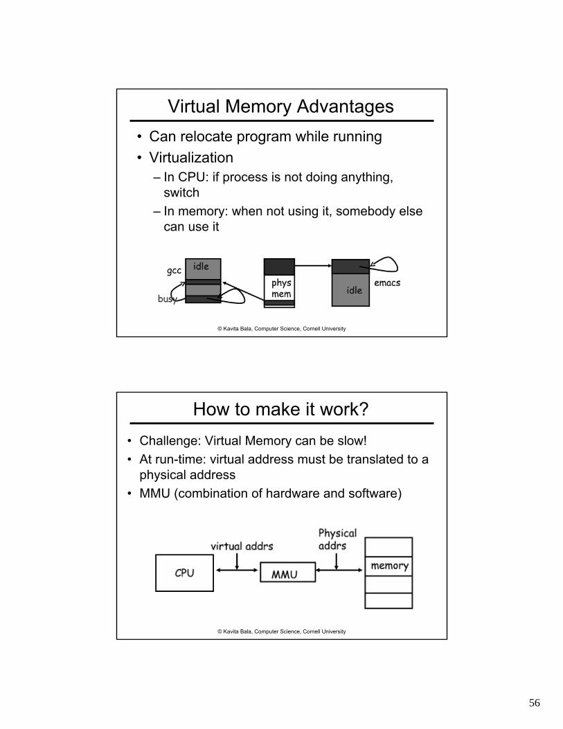
• Memory Management Unit (MMU)– Combination of hardware and software
56
© Kavita Bala, Computer Science, Cornell University
Virtual Memory Advantages• Can relocate program while running• Virtualization
– In CPU: if process is not doing anything, switch
– In memory: when not using it, somebody else can use it
© Kavita Bala, Computer Science, Cornell University
How to make it work?• Challenge: Virtual Memory can be slow!• At run-time: virtual address must be translated to a
physical address• MMU (combination of hardware and software)

57
© Kavita Bala, Computer Science, Cornell University
Two Programs Sharing Physical Memory
Program 1virtual address space
main memory
• The starting location of each page (either in main memory or in secondary memory) is contained in the program’s page table
Program 2virtual address space
swapspace
© Kavita Bala, Computer Science, Cornell University
Page Table for Translation
Physical pagebase addr
Main memory
Disk storage
Virtual page #
V11111101010
Page Table(in main memory)
Offset
Physical page #
Offset
swapspace

58
© Kavita Bala, Computer Science, Cornell University
Virtual Addressing with a Cache• Thus it takes an extra memory access to
translate a VA to a PA
CPU Trans-lation Cache Main
Memory
VA PA miss
hitdata
• This makes memory (cache) accesses very expensive (if every access was really two accesses)
© Kavita Bala, Computer Science, Cornell University
A TLB in the Memory Hierarchy
• A TLB miss: – If the page is not in main memory, then it’s a
true page faultTakes 1,000,000’s of cycles to service a page fault
• TLB misses are much more frequent than true page faults
CPU TLBLookup Cache Main
Memory
VA PA miss
hit
data
Trans-lation
hit
miss

59
© Kavita Bala, Computer Science, Cornell University
Virtual vs. Physical Caches
• L1 (on-chip) caches are typically virtual• L2 (off-chip) caches are typically physical
CPUCacheSRAM
MemoryDRAM
addr
dataMMU
CacheSRAM
MMUCPU MemoryDRAM
addr
data
Cache works on physical addresses
Cache works on virtual addresses
© Kavita Bala, Computer Science, Cornell University
Address Translation• Translation is done through the page table
– A virtual memory miss (i.e., when the page is not in physical memory) is called a page fault

60
© Kavita Bala, Computer Science, Cornell University
Hardware/Software Boundary• Virtual to physical address translation is
assisted by hardware?– Translation Lookaside Buffer (TLB) that
caches the recent translationsTLB access time is part of the cache hit timeMay allot an extra stage in the pipeline for TLB access
– TLB missCan be in software (kernel handler) or hardware
© Kavita Bala, Computer Science, Cornell University
Hardware/Software Boundary• Virtual to physical address translation is
assisted by hardware?– Page table storage, fault detection and
updatingPage faults result in interrupts (precise) that are then handled by the OSHardware must support (i.e., update appropriately) Dirty and Reference bits (e.g., ~LRU) in the Page Tables

61
© Kavita Bala, Computer Science, Cornell University
© Kavita Bala, Computer Science, Cornell University
Paging

62
© Kavita Bala, Computer Science, Cornell University
© Kavita Bala, Computer Science, Cornell University
Exceptions• System calls are control transfers to the OS, performed
under the control of the user program
• Sometimes, need to transfer control to the OS at a time when the user program least expects it– Division by zero,– Alert from power supply that electricity is going out, – Alert from network device that a packet just arrived,– Clock notifying the processor that clock just ticked
• Some of these causes for interruption of execution have nothing to do with the user application
• Need a (slightly) different mechanism, that allows resuming the user application

63
© Kavita Bala, Computer Science, Cornell University
Terminology• Trap
– Any kind of a control transfer to the OS• Syscall
– Synchronous, program-initiated control transfer from user to the OS to obtain service from the OS
– e.g. SYSCALL• Exception
– Asynchronous, program-initiated control transfer from user to the OS in response to an exceptional event
– e.g. Divide by zero• Interrupt
– Asynchronous, device-initiated control transfer from user to the OS
– e.g. Clock tick, network packet
© Kavita Bala, Computer Science, Cornell University
Memory-Mapped I/O
ProcessorAddress Space
I/O DeviceMemory
and ControlRegisters

64
© Kavita Bala, Computer Science, Cornell University
DMA: Direct Memory AccessNon-DMA transfer: I/O device CPU RAM– for (i = 1 .. n)
CPU sends transfer request to deviceI/O writes data to bus, CPU reads into registersCPU writes data to registers to memory
DMA transfer: I/O device RAM– CPU sets up DMA request on device– for (i = 1 .. n)
I/O device writes data to bus, RAM reads data
CPU RAM
DISK
CPU RAM
DISKBased on lecture from Kevin Walsh
© Kavita Bala, Computer Science, Cornell University
Disk Physics
Typical parameters :1 spindle1 arm assembly1-4 platters1-2 sides/platter1 head per side(but only 1 active head at a time)4,200 – 15,000 RPM

65
© Kavita Bala, Computer Science, Cornell University
Technology Trends• DRAM capacity
– Increased– Reduced cost
• Moore’s Law– Speed?– Not really
DRAM capacity
© Kavita Bala, Computer Science, Cornell University
Moore’s Law
• Law about transistor count

66
© Kavita Bala, Computer Science, Cornell University
Review: Performance Summary
• Performance depends on– Algorithm: affects IC, possibly CPI– Programming language: affects IC, CPI– Compiler: affects IC, CPI– Instruction set architecture: affects IC, CPI, Tc
cycle ClockSeconds
nInstructiocycles Clock
ProgramnsInstructioTime CPU ××=
© Kavita Bala, Computer Science, Cornell University
Why Multicore?
• Moore’s law– A law about transistors– Smaller means faster transistors
• Power consumption growing with transistors

67
© Kavita Bala, Computer Science, Cornell University
© Kavita Bala, Computer Science, Cornell University
Power Trends
• In CMOS IC technology
FrequencyVoltageload CapacitivePower 2 ××=
×1000×30 5V → 1V

68
© Kavita Bala, Computer Science, Cornell University
Uniprocessor Performance
Constrained by power, instruction-level parallelism, memory latency
© Kavita Bala, Computer Science, Cornell University
Why Multicore?• Moore’s law
– A law about transistors– Smaller means faster transistors
• Power consumption growing with transistors
• The power wall– We can’t reduce voltage further– We can’t remove more heat
• How else can we improve performance?

69
© Kavita Bala, Computer Science, Cornell University
Intel’s argument
© Kavita Bala, Computer Science, Cornell University
1.2x
1.6x

70
© Kavita Bala, Computer Science, Cornell University
Amdahl’s Law• Task: serial part, parallel part• As number of processors increases,
– time to execute parallel part goes to zero– time to execute serial part remains the same
• Serial part eventually dominates• Must parallelize ALL parts of task
© Kavita Bala, Computer Science, Cornell University
Amdahl’s Law• Consider an improvement E• F of the execution time is affected• S is the speedup

71
© Kavita Bala, Computer Science, Cornell University
Multithreaded Processes
© Kavita Bala, Computer Science, Cornell University
Shared counters• Usual result: works fine.• Possible result: lost update!
• Occasional timing-dependent failure ⇒ Difficult to debug• Called a race condition
hits = 0 + 1
read hits (0)
hits = 0 + 1read hits (0)
T1 T2
hits = 1
hits = 0time

72
© Kavita Bala, Computer Science, Cornell University
Race conditions• Def: a timing dependent error involving shared
state – Whether it happens depends on how threads
scheduled: who wins “races” to instructions that update state
– Races are intermittent, may occur rarelyTiming dependent = small changes can hide bug
– A program is correct only if all possible schedules are safe
Number of possible schedule permutations is hugeNeed to imagine an adversary who switches contexts at the worst possible time
© Kavita Bala, Computer Science, Cornell University
Critical Sections• Basic way to eliminate races: use critical
sections that only one thread can be in– Contending threads must wait to enter
CSEnter();Critical section
CSExit();
T1 T2time
CSEnter();Critical section
CSExit();
T1 T2

73
© Kavita Bala, Computer Science, Cornell University
Mutexes• Critical sections typically associated with mutual
exclusion locks (mutexes)• Only one thread can hold a given mutex at a
time• Acquire (lock) mutex on entry to critical section
– Or block if another thread already holds it• Release (unlock) mutex on exit
– Allow one waiting thread (if any) to acquire & proceed
pthread_mutex_lock(m);hits = hits+1;
pthread_mutex_unlock(m);
T1 T2
pthread_mutex_lock(m);hits = hits+1;
pthread_mutex_unlock(m);
pthread_mutex_init(m);
© Kavita Bala, Computer Science, Cornell University
Protecting an invariant// invariant: data is in buffer[first..last-1]. Protected by m.pthread_mutex_t *m;char buffer[1000];int first = 0, last = 0;
void put(char c) {pthread_mutex_lock(m);buffer[last] = c;last++;pthread_mutex_unlock(m);
}
• Rule of thumb: all updates that can affectinvariant become critical sections.
char get() {pthread_mutex_lock(m);char c = buffer[first];first++;pthread_mutex_unlock(m);
}
X what if first==last?

74
© Kavita Bala, Computer Science, Cornell University
FIGURE A.2.5 Basic unified GPU architecture. Example GPU with 112 streaming processor (SP) cores organized in 14 streaming multiprocessors (SMs); the cores are highly multithreaded. It has the basic Tesla architecture of an NVIDIA GeForce 8800. The processors connect with four 64-bit-wide DRAM partitions via an interconnection network. Each SM has eight SP cores, two special function units (SFUs), instruction and constant caches, a multithreaded instruction unit, and a shared memory. Copyright © 2009 Elsevier, Inc. All rights reserved.
© Kavita Bala, Computer Science, Cornell University
Where is the Market?
290
933
488
1143
892
1354
862
1294
1122
1315
0
200
400
600
800
1000
1200
1998 1999 2000 2001 2002
EmbeddedDesktopServers
Mill
ions
of C
ompu
ters

75
© Kavita Bala, Computer Science, Cornell University
© Kavita Bala, Computer Science, Cornell University
Where to?
• Smart Dust….

76
© Kavita Bala, Computer Science, Cornell University
Where to?• CS 3110: Better concurrent programming
• CS 4410: The Operating System!
• CS 4450: Networking
• CS 6620: Graphics
• And many more…
© Kavita Bala, Computer Science, Cornell University
Thank you!