Embed Size (px)
Citation preview

The Evolution of Failure Analysis at NASA’s Kennedy Space Center and the Lessons
Learned
M. Clara Wright, National Aeronautics and Space Administration (NASA), Kennedy Space
Center, FL
Victoria L. Long, National Aeronautics and Space Administration (NASA), Kennedy Space
Center, FL
Steve McDanels, National Aeronautics and Space Administration (NASA), Kennedy Space
Center, FL
Introduction:
The United States has had four manned launch programs and three station programs since the era
of human space flight began in 1961. The launch programs, Mercury, Gemini, Apollo, and
Shuttle, and the station programs, Skylab, Shuttle-Mir, and the International Space Station (ISS),
have all been enormously successful, not only in advancing the exploration of space, but also in
advancing related technologies. As each subsequent program built upon the successes of
previous programs, they similarly learned from their predecessors’ failures. While some failures
were spectacular and captivated the attention of the world, most only held the attention of the
dedicated men and women working to make the missions succeed.
Long-Duration Space Operations:
Skylab
The first U.S-made orbiting space station was Skylab. Made from Apollo-era hardware, the
experimental space station would serve as a location for science experiments, solar and Earth
https://ntrs.nasa.gov/search.jsp?R=20150023113 2018-09-01T02:58:31+00:00Z

observations, and evaluation of the response of the human body to a micro-gravity environment.
Three missions to Skylab resulted in over 300 science experiments on solar astronomy, Earth
observations, human response to the space environment, and materials science. NASA’s
Kennedy Space Center was tasked with launching the hardware and the crew using legacy
facilities from the Apollo program.
The two primary goals of the Skylab program were to prove that humans could live in space for
extended periods of time and to expand our knowledge of solar astronomy using a space-based
telescope. Each of the three crews that partook in the Skylab program were trained to use the
astronomical telescope, photograph the Earth at selected wavelengths, perform experiments of
material behavior in micro gravity, and study their own response to space environment through a
myriad of medical experiments. Experiments were completed over a period of 171 days and 13
hours, including over 200,000 frames returned to Earth from solar astronomy and Earth
observations.
Successes from the Skylab program could have been overshadowed by accidental early
deployment of a meteor shield during launch which was then torn off by atmospheric drag,
causing problems maintaining a constant internal module temperature. A parasol-like shield was
designed, then launched and deployed by the first Skylab crew thus fixing the problem (Figure
1). Skylab maintained its near-circular orbit at an altitude of 435 km (270 miles) throughout the
life of the program, and remained on orbit for another 5 and ½ years until it re-entered Earth’s
atmosphere and disintegrated over the Indian Ocean and Western Australia in 1979.

Figure 1. Skylab orbiting the Earth, as seen by a departing crew capsule after one of the long-
duration missions. The parasol-like repair shield is seen at the bottom of the image, a fix that
enabled mission and program success.
International Space Station
Following the successes of the Skylab program, there was great interest within the scientific
community to construct another orbiting station for conducting further research that could only
be performed in micro gravity or low-Earth orbit. Skylab was not designed to be permanently
occupied. In 1984, NASA was given an initiative to design another space station. It was
proposed that the new space station would be an international collaboration including Canada,
Japan and the partners of the European Space Agency: Belgium, Denmark, France, Germany,
Italy, the Netherlands, Norway, Spain, Sweden, Switzerland and the United Kingdom, with the
intention that it be used for space experiments, satellite repairs, and as an intermediate base for
space exploration. The concept of space station Freedom arose from these requirements [1]. In
the 1990s the design was streamlined and the international collaboration extended to include
Russia, thus the start of the International Space Station (ISS). Five space agencies were an
integral part of the construction: NASA, the Russian Space Agency Roscosmos, the Canadian
Space Agency (CSA), the European Space Agency (ESA) and the Japan Aerospace Exploration

Agency (JAXA). The first NASA node, Unity, was launched in Space Shuttle Endeavour from
the Kennedy Space Center during Space Transportation System (STS) mission 88 in December
of 1998. Construction of the ISS was carried out over 14 years with over 115 space flights on
five different launch vehicles with coordination of all the international partners and included
ESA’s Columbus module and JAXA’s Kibo module. Figure 2 shows the relative length of the
“backbone” of the ISS, with a truss length of 357.5 feet, solar array length of 239.4 feet, mass of
924,739 lbs and habitable volume of 13, 696 cubic feet [2] (15).
Figure 2. Relative size of the completed ISS in relation to a U.S. football field (left) and final
configuration of the ISS after completion of construction (right). Credit: NASA
NASA KSC was responsible for launching 28 major components during station assembly. As
various pieces of hardware, including pressurized compartments and structural trusses, were
processed at KSC, troubleshooting problems on the ground was of the utmost importance in
ensuring successful integration in space. The team knew that there was only one chance to get
everything right. However, as meticulous as the NASA and contractor team was from design to
launch of hardware, there were unforeseen problems that arose after construction. One such
problem necessitated the assistance of engineers across the United States to perform failure
analysis on hardware that was already in low-Earth orbit (LEO).

Failure in LEO: the Solar Alpha Rotary Joint (SARJ):
STS-117 mission
On June 8, 2007, the Space Shuttle Atlantis lifted off from Launch Complex 39A at the Kennedy
Space Center to deliver the S3/S4 truss segment to the International Space Station (ISS) as part
of ISS assembly flight 13A. The STS-117 mission was the fifth Space Shuttle launch after the
Space Shuttle Columbia disaster and the third ISS assembly mission after the Return to Flight.
The hardware delivered during the STS-117 mission was to be located on the starboard side of
the ISS and was designated as the S3/S4 truss segments, which was the eighth of eleven total
segments that would go on to form the Integrated Truss Structure. The trusses form the 357 foot
long backbone of the ISS and are attached to the pressurized modules that are the living, storage,
service, and laboratory space for the ISS crew [3].
The Solar Array Wings are also attached to the Integrated Truss Structure and provide the power
to the ISS. The S3/S4 truss segment provided the attach-point for the first set of starboard-side
Solar Array Wings and also contained the starboard Solar Alpha Rotary Joint (SARJ), which is
the mechanism for rotating the solar arrays for alignment with the sun [3]. The portside SARJ
had been installed during the STS-115 mission in late 2006 as part of the mirror-image P3/P4
truss segment and had been in operation since that time [4].
SARJ hardware overview
The SARJ is 10.5 feet in diameter, weighs over 2,500 pounds, and is used to position the solar
arrays to track the sun during orbit as shown in Figure 3. The SARJ is capable of power and data

transfer across the rotating joint interface, thereby allowing for a full 360 degree rotation
approximately once every 90 minutes in sync with the orbit of the ISS [3].
The SARJ consists of two race rings, twelve independent Trundle Bearing Assemblies (TBAs),
two Drive Lock Assemblies, and two Rotary Joint Motor Controllers. The race rings have a
triangular cross-section and are composed of nitrided 15-5 precipitation hardened (PH) stainless
steel forgings. The inboard race ring is stationary and the Trundle Bearing Assemblies are fixed
to this race ring. The outboard race ring rotates using the Drive Lock Assemblies, which are
controlled by the Rotary Joint Motor Controllers. Trundle Bearing Assembly rollers, which are
oriented in a triangle that correlates with the race ring cross-section, ride on the outboard race
ring and provide a mechanical connection between the two race rings. The rollers are composed
of 440C stainless steel and are gold-plated to provide lubrication between the roller surface and
the race ring [5].
Figure 3. Location of port and starboard SARJ on the truss of the ISS (left) and details of the
SARJ mechanism (right). Credit: NASA
STS-117 Mission overview

After an overnight stay in the Quest airlock in order to remove nitrogen from their bloodstreams,
astronauts Danny Olivas and Jim Reilly performed the first extravehicular activity (EVA) for the
mission to install the mechanical and electrical connections for the S3/S4 truss segment using the
Canadarm 2 with the help of their fellow STS-117 crew [6]. During the second and fourth
EVAs, astronauts Patrick Forrester and Steven Swanson removed the launch locks and restraints
so that the SARJ would be free to rotate when activated [7]. ISS flight controllers at the Johnson
Space Center tested and activated the SARJ, resulting in four fully operational solar arrays
powering the ISS by the end of the STS-117 mission. The crew was cleared for landing,
returning Astronaut Suni Williams home from a record-breaking 189 day stay aboard the ISS [8].
The Problem
Approximately three months after the installation of the starboard SARJ, the health and status
data for the joint revealed a potential issue with the mechanism. The first anomalous sign of a
problem was an increasing difference between the velocity that was commanded and the actual
velocity of the joint, as seen at Mission Control in the Johnson Space Center. An extensive
ground investigation was initiated to find the cause, resulting in the software and controller being
cleared, thereby indicating a mechanical problem with the starboard SARJ. Additional signs of
an issue were becoming evident and the primary focus was now on the increased current that was
necessary to drive the Rotary Joint Motor Controllers, which directly correlated to the SARJ
torque. Over a period of two months, the necessary current to drive the joint had first doubled
and then quadrupled over nominal, indicating that the torque was dangerously close to margin
and could possibly lead to an unrecoverable situation [5].
Troubleshooting during the STS-120 mission

The next planned mission to ISS was STS-120 on Space Shuttle Discovery. STS 120 launched
on October 23, 2007 primarily to deliver the Harmony module to the ISS, a water, air, and power
hub that would redirect resources to a number of laboratory modules set to launch in 2008. The
crew also had a busy EVA schedule involving the relocation of a portside truss segment so that
power could be provided from an additional Solar Array Wing [9].
During the second EVA, a task was added to the planned activities for astronaut Dan Tani: to
inspect the Multi-Layer Insulation covers on the starboard SARJ for evidence of the cause of the
anomalous data, such as a micrometeoroid impact or an interference problem. Upon finding no
external cause of the problem, Tani removed the insulation cover and observed apparent metallic
debris gathered on the magnetic Trundle Bearing Assembly and a mottled appearance of the race
ring surface. Tani gathered fragments using polyimide tape so that the pieces could be returned
for analysis by engineers on the ground [10].
Concerns over the damage observed during the inspection resulted in a decision by mission
managers to limit the starboard SARJ operation, to inspect the portside SARJ during the third
EVA, and to devote the fourth EVA to an in-depth inspection of the starboard SARJ. Astronaut
Scott Parazynski reported that the portside race ring had no observable damage, thereby allowing
continued operation of the port SARJ [11].
The priority for the fourth EVA abruptly changed when a tear occurred in a blanket during the
deployment of a portside solar array, which was one of the Discovery crew’s primary mission
objectives. With the available time for the STS-120 mission quickly dwindling, the fourth EVA
was dedicated to fixing the solar array issue; further inspection of the starboard SARJ was
postponed to a later mission [12]. The initial root cause investigation for the SARJ anomaly
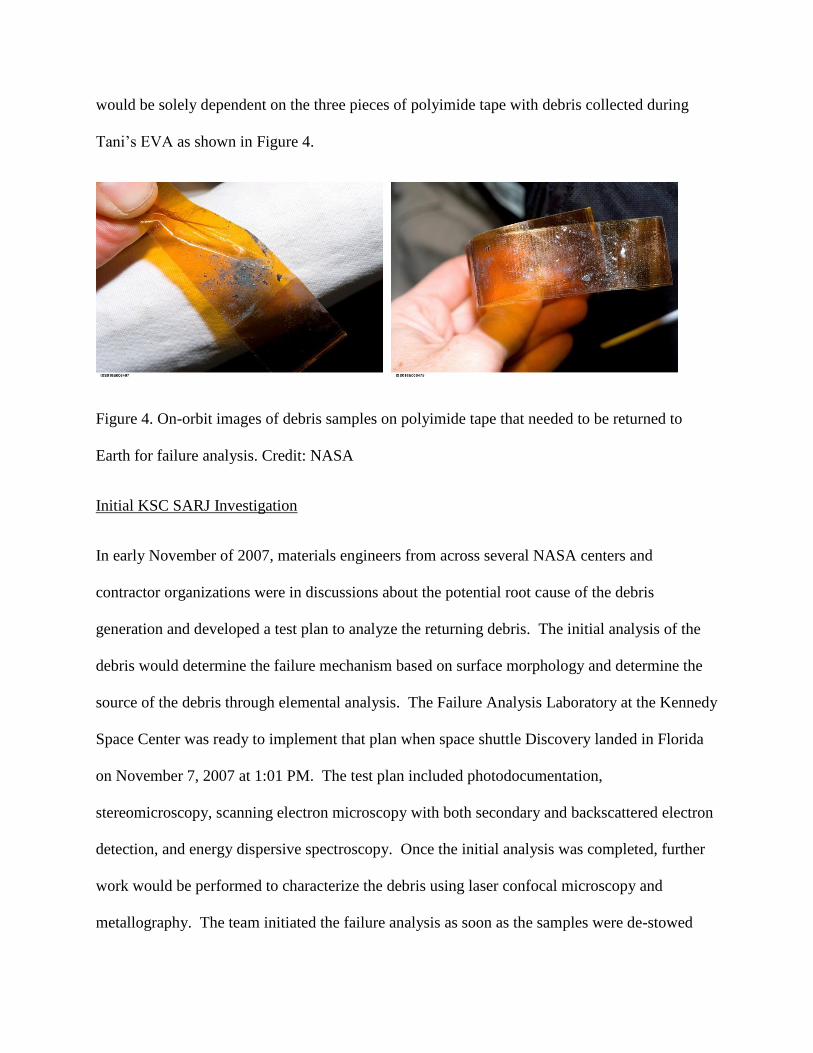
would be solely dependent on the three pieces of polyimide tape with debris collected during
Tani’s EVA as shown in Figure 4.
Figure 4. On-orbit images of debris samples on polyimide tape that needed to be returned to
Earth for failure analysis. Credit: NASA
Initial KSC SARJ Investigation
In early November of 2007, materials engineers from across several NASA centers and
contractor organizations were in discussions about the potential root cause of the debris
generation and developed a test plan to analyze the returning debris. The initial analysis of the
debris would determine the failure mechanism based on surface morphology and determine the
source of the debris through elemental analysis. The Failure Analysis Laboratory at the Kennedy
Space Center was ready to implement that plan when space shuttle Discovery landed in Florida
on November 7, 2007 at 1:01 PM. The test plan included photodocumentation,
stereomicroscopy, scanning electron microscopy with both secondary and backscattered electron
detection, and energy dispersive spectroscopy. Once the initial analysis was completed, further
work would be performed to characterize the debris using laser confocal microscopy and
metallography. The team initiated the failure analysis as soon as the samples were de-stowed

and delievered to the laboratory, at approximately 4:30 PM, and concluded their initial analysis
in less than 10 hours. Because of the unique nature of the samples, work had to be expedited yet
proper handling and documentation was of the utmost importance. Figure 5 shows the team
during the removal of the samples in preparation for detailed photodocumentation.
Figure 5. Meticuluous handling of the starboard SARJ samples was carried out by the team
during the investigation. Credit: P. Marciniak/NASA KSC
The three pieces of polyimide tape collected by astronaut Tani and returned to Earth were
photodocumented and initially observed in a stereomicroscope. The particles sizes for the debris
ranged from very fine particulate less than 100 µm up to approximately 1 mm. The first
significant observation was apparent machine markings still present on the surface of some of the
larger fragments and fracture features visible on other fragments (Figure 6). Additionally, the
debris was classified as fine particulates, flattened agglomerations, and large chips. The debris
had a slight magnetic response [13].

Figure 6. Stereomicroscopic inspection revealed that the shards included both original surface
finish (left) and fracture features (right). Credit: T. Long & C. Wright/NASA KSC
Energy dispersive X-ray spectroscopy (EDS) via a scanning electron microscope (SEM) used in
variable pressure low vacuum mode gave the first definitive answer about where the debris
originated. The ISS SARJ system engineers had determined that the four most probable sources
of the debris were the nitrided 15-5 precipitation hardened (PH) stainless steel race ring, the
gold-plated 440C stainless steel rollers from the TBA, the gold-plated 13-8 Mo stainless steel
pinions, and the nickel-phosphorous plated 17-7 PH stainless steel centering springs. Since the
EDS analysis clearly showed that the debris shards were composed of 15-5 PH stainless steel
with nitrogen present throughout the samples, the source of the debris was determined to be the
nitrided case of one of the starboard SARJ race ring surfaces. The only other metal fragments
present on the tape were a small number of isolated gold pieces, which originated from the gold-
plated 440C rollers.
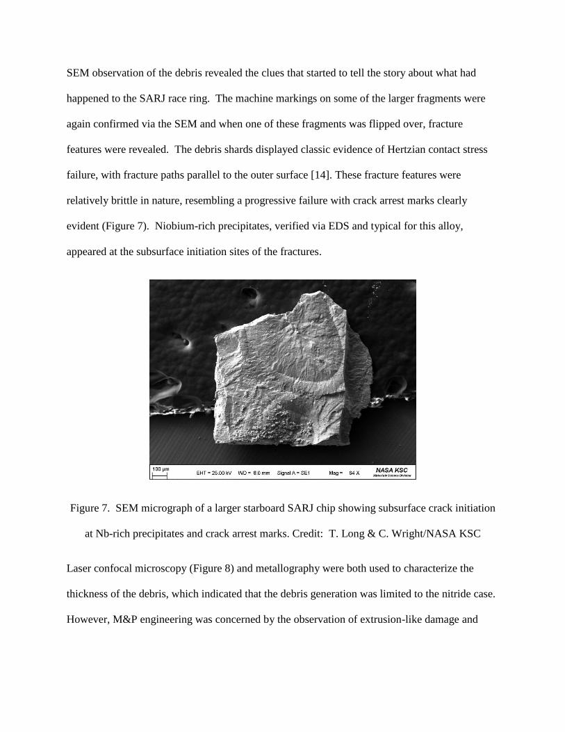
SEM observation of the debris revealed the clues that started to tell the story about what had
happened to the SARJ race ring. The machine markings on some of the larger fragments were
again confirmed via the SEM and when one of these fragments was flipped over, fracture
features were revealed. The debris shards displayed classic evidence of Hertzian contact stress
failure, with fracture paths parallel to the outer surface [14]. These fracture features were
relatively brittle in nature, resembling a progressive failure with crack arrest marks clearly
evident (Figure 7). Niobium-rich precipitates, verified via EDS and typical for this alloy,
appeared at the subsurface initiation sites of the fractures.
Figure 7. SEM micrograph of a larger starboard SARJ chip showing subsurface crack initiation
at Nb-rich precipitates and crack arrest marks. Credit: T. Long & C. Wright/NASA KSC
Laser confocal microscopy (Figure 8) and metallography were both used to characterize the
thickness of the debris, which indicated that the debris generation was limited to the nitride case.
However, M&P engineering was concerned by the observation of extrusion-like damage and
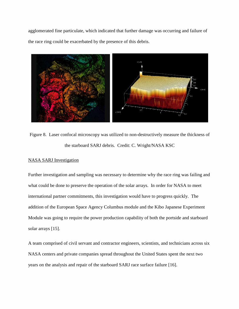
agglomerated fine particulate, which indicated that further damage was occurring and failure of
the race ring could be exacerbated by the presence of this debris.
Figure 8. Laser confocal microscopy was utilized to non-destructively measure the thickness of
the starboard SARJ debris. Credit: C. Wright/NASA KSC
NASA SARJ Investigation
Further investigation and sampling was necessary to determine why the race ring was failing and
what could be done to preserve the operation of the solar arrays. In order for NASA to meet
international partner commitments, this investigation would have to progress quickly. The
addition of the European Space Agency Columbus module and the Kibo Japanese Experiment
Module was going to require the power production capability of both the portside and starboard
solar arrays [15].
A team comprised of civil servant and contractor engineers, scientists, and technicians across six
NASA centers and private companies spread throughout the United States spent the next two
years on the analysis and repair of the starboard SARJ race surface failure [16].

Expedition 16 Sample Analysis
In December of 2007, approximately a month after the original failure analysis at the KSC
laboratory, Expedition 16 astronauts Dan Tani and Peggy Whitson performed a nearly seven
hour EVA which focused on inspecting the starboard SARJ race rings and bearings beneath 16
of the 22 drive lock assembly covers. Various amounts of the similar types of debris were
observed, while one of TBAs was removed for evaluation back on Earth. During EVAs 13 and
14, 29 tape samples, containing hundreds of fragments of debris, were collected. High-
resolution photographs of the raceway surfaces revealed surface degradation with debris
adhering to the TBAs (Figure 9).

Figure 9. On-orbit photograph of one of three raceway surfaces of the starboard SARJ during
Expedition 16 EVA showing damage to the race and magnetized debris on the TBA. Credit:
NASA
The 29 tape samples and TBA removed during Expedition 16 could not be returned to Earth until
the return of the next Shuttle mission, STS 122, due to space limitations. The samples were
finally delivered to the NASA Failure Analysis Laboratory at the Kennedy Space Center in
February of 2008 for analysis. Analysis determined that the chips collected during the
Expedition 16 EVAs 13 and 14, as well as those harvested from the removed TBA, were similar
in appearance, composition, and failure mode to those analyzed from the first SARJ debris
samples returned on STS-120. Predominantly, nitrided 15-5 PH chips were present as both fine
debris and fractured fragments. The fine debris was observed in three forms: as individual
particles, as particles agglomerated but with little mechanical adhesion, and as agglomerates that
appeared rolled and exhibiting an extruded appearance. It was determined that the majority of the
debris was less than 50 µm in diameter and covered a significant amount of the tapes’ surface
areas. Based on thickness, composition, and microstructure, fracture was limited to the nitrided
case of the primary race ring. Fragment thicknesses were comparable to those from the previous
analysis and within the range of the hardened nitrided case specifications, which was required to
be less than 170 µm. EDS verified the presence of nitrogen throughout the fragments. Etching
of cross-sectional samples revealed the nitrided case layer microstructure and transgranular
secondary microcracking. The SARJ fragments did not display a martensitic core microstructure
or case-core interface, indicating that the spalling was limited to the nitrided case. Figures 10 to
13 show representative samples from the investigation [17, 18].

Figure 10. Photograph of two representative SARJ sample tapes from the Expedition 16 spacewalks
showing a dust-like fine debris covering the majority of the adhesive tape surface as well as some larger
fragments that were evident when visually inspected. Credit: P. Marciniak/NASA KSC
Figure 11. Representative SEM micrographs of agglomerated (top) and extruded (bottom) SARJ particles
from Expedition 16 EVA. Credit: C. Wright/NASA KSC

Figure 12. Fracture features of the Expedition 16 EVA samples were similar to those from the
original STS 120 samples, with subsurface crack initiation and crack arrest marks. Credit: C.
Wright/NASA KSC
Figure 13. Etched starboard SARJ fragment showing transgranular crack propagation and
fracture within the nitride case of the 15-5 PH race surface. Credit: P. Marciniak & B.
Tucker/NASA KSC
Of particular interest to the Agency-wide investigation team was the presence of gold plating that
was the intended lubricant for the contact surface between the 15-5PH race ring and the 440C

TBA rollers [19]. The gold plating should have been metallurgically bonded to the substrate, but
Figure 14 shows that microscopy tape could easily detach the plating in ribbons. Additional
investigation by the engineering team revealed that the loss of gold plating was occurring on
flight spares, and that artificially-aged samples from new gold-plated rollers were experiencing a
loss of adhesion due to corrosion at the interface between the plating and substrate. The
resulting inadequate lubrication led to high levels of friction and roller contact conditions, which
ultimately led to damage of the race ring’s nitride surface as subsurface loads moved to the
case/core interface, which caused spalling to initiate at sub-surface discontinuities, in this case
niobium-rich precipitates, which acted as stress concentrators. It was theorized that weak
magnetic forces in the microgravity environment caused the debris to stay within the SARJ,
causing the larger chips to be pulverized and then agglomerate. An additional conclusion by the
investigation team was that the SARJ design had a kinematic susceptibility to tip due to roller
mistracking, which, combined with the high frictional forces, led to high roller-edge stresses and
resulted in the 15-5PH race surface spalling at the nitride case [20].

Figure 14. Stereomicroscope image of TBA sample, taken from an inner 45 roller surface. Gold
plating was observed flaking off of the roller sides as samples were prepared. Credit: C.
Wright/NASA KSC
Post-Analysis On-Orbit Inspection
The starboard SARJ was not allowed to function in normal mode until the debris was cleaned
and the race surface was again considered to be fully functional. During STS-124 in June of
2008, spacewalkers Mike Fossum and Ron Garan demonstrated techniques to clean the debris,
including using a specially-designed grease gun to lubricate the outer race ring (Figure 15), and
replaced one of the TBAs [21]. The port SARJ, which was functioning nominally, was
inspected. Small amounts of debris were collected and returned to Earth for analysis.
Figure 15. Astronauts Mike Fossum and Ron Garan testing a grease gun specifically designed to
aid in cleaning of the starboard SARJ race ring debris. Credit: NASA
The Repair on STS-126, November 2008

After the investigation team concluded that high frictional forces due to a lack of lubrication
were causing the spalling, NASA decided to use Braycote grease during the STS‐126 mission
(Figure 16) in November of 2008 to provide a lower coefficient of friction. Braycote grease is a
vacuum-stable grease that was designed for the extreme environment of space. On the starboard
SARJ, the debris was cleaned using terry cloth EVA wipes and a scraper tool for the flattened
pieces, followed by a greased wipe on all surfaces. The grease gun that was tested during STS-
124 was used to apply the Braycote to both the starboard and port SARJ race ring surfaces. The
SARJs were then rotated to allow the rollers in the TBAs to spread the lubricant. The TBAs on
the starboard SARJ that had suspect gold plating and were filled with debris were replaced
during an EVA in the course of STS-126 [22]. Although the starboard SARJ has a redundant
inboard race ring, it was decided at the time not to use the redundancy so as to maintain an
available back-up. At the time it was expected that a long-term fix, including a race re-design,
was going to be required. However, the cleaning and lubricating procedures’ efficacy resulted in
reverting to continuous autotrack operations for the starboard SARJ in 2010 [23, 24]. Had the
permanent repair been necessary, it would have taken 10 spacewalks for installation of a new
race ring assembly.

Figure 16. Astronaut Shane Kimbrough removing debris and applying lubrication around the
starboard SARJ during the STS-126 mission's second spacewalk. Credit: NASA
What about the Port-SARJ?
The port SARJ was inspected during various spacewalks as the starboard SARJ investigation
was underway. The port SARJ had been installed and activated during STS-115 in September of
2006 and had been operating nominally. As a preventative measure, the port SARJ was
lubricated during STS-126 in November of 2008 and re-lubricated after three years of greased
operation in May of 2011 during STS 134 [24]. Analysis of debris sampled during the re-
lubrication operation in 2011 revealed very small amounts of wear debris from the port race ring
nitrided case. It was decided that monitoring of the mechanism would be carried out using
telemetry data of the SARJ current loads.
Conclusion:

By its very nature, the exploration of space is wrought with difficulty. Failure is an ever-present
possibility. One can either ignore the failure and its cause and press on, or learn from that
failure. Failure analysis at the Kennedy Space Center has evolved from the early space programs
to today. Advances in equipment have made the field more portable, usually taking materials
engineers and failure analysts to the launch pads, vehicles, and associated facilities to perform in-
situ failure analysis. With the extended presence of humans in low-Earth orbit, remote failure
analysis has become essential. Whereas previously NASA relied upon institutional knowledge
of launch structures and ground support equipment at KSC to perform failure analysis on-site,
investigations have extended to include multiple NASA centers, contractors across the United
States, and even astronauts on orbit aboard the ISS, while taking into consideration the effects of
failures to international partners. As NASA continues to extend long-duration missions on the
ISS and explore deep space, remote failure analysis is a necessity. Cross-country and
international teams supporting operations in micro-gravity must overcome many barriers to
communicate the technical facts, while working toward the same goal: the safest possible
exploration beyond Earth.
[1]. NASA’s Space Station Program: Evolution and Current Status, Testimony before the
House Science Committee, April 4, 2001
[2]. International Space Station Facts and Figures,
http://www.nasa.gov/mission_pages/station/main/onthestation/facts_and_figures.html
[3]. STS-117 Press kit
[4]. STS-115 Press kit
[5]. The International Space Station Solar Alpha Rotary Joint Anomaly Investigation,
NASA, 2009

[6]. STS-117 Status report # 14
[7]. STS-117 Status report #20
[8]. STS-117 Status report #21
[9]. STS-120 Press kit
[10]. STS 120 Status report #12
[11]. STS-120 Status report #16
[12]. STS-120 Status report #18
[13]. STS-120 International Space Station (ISS) Starboard Solar Alpha Rotary Joint (SARJ)
Debris Analysis, Internal report KSC-MSL-2007-0499
[14]. Wulpi, D.J., Understanding How Components Fail. ASM International. 1985. p. 199.
[15]. http://www.thespacereview.com/article/1136/1
[16]. Examination of Surface Residuals Obtained during Re-Lubrication of the International
Space Station (ISS) Solar Alpha Rotary Joint (SARJ), J. L. Golden, J. E. Martinez,
Microscopy and Microanalysis (M&M) 2012, 8/31/2012
[17]. Wright, M.C., “International Space Station (ISS) Expedition 16 Starboard Solar Alpha
Rotary Joint (s-SARJ) Debris Analysis,” Internal report KSC-MSL-2008-0099, (2008)
[18]. Logistical and Analytical Approach to a Failure Aboard the International Space
Station, S. McDanels, M. C. Wright, V. Salazar, D. Lubas, B. Tucker. Society for the
Advancement of Material and Process Engineering (SAMPE), Tokyo, Japan, 2008
[19]. Solar Alpha Rotary Joint Anomaly: The Materials & Processes Perspective; Aging
Aircraft 2009 Conference, E. Basta, R. Dagupta, J. Figert, G. Jerman, C. Wright, D.
Petrakis, J. Golden.
[20]. NASA Engineering Safety Center (NESC) support to the ISS SARJ Investigation,
http://www.nasa.gov/offices/nesc/home/Feature_SARJ_051809.html

[21]. STS124 (June 2008) Mission Status Updates (http://www.nasa.gov/rss/nasa-pao-
rss.xml)
[22]. STS126 Press kit
[23]. http://www.spaceflightnow.com/shuttle/sts126/081125fd12/index2.html, “Station boss
happy with SARJ and water recycler repairs”, November 25, 2008
[24]. Examination of Surface Residuals Obtained during Re-Lubrication of the International
Space Station (ISS) Solar Alpha Rotary Joint (SARJ); J. L Golden, J. E. Martinez,
Microscopy & Microanalysis 2012