Embed Size (px)
Citation preview
-7831
A_0783-0784_F11-02_cENG
-7841
A_0783-0784_F11-02_cENG cENG 2nd
1. Lead Screw Support Units P.791~794Features:Optimal Lead Screw Support Units use two preload-adjusted radial bearings.eSupport Unit Sets combined Fixed Side Support Unit with Support Side Support Unit are available for lower prices since 2012.
Lineup : Square / Round
Fixed Side Square Support Unit Stop Plate Set for Position Indictor Mount Support Side Square Support Unit
For Position Indicators, select from wP.811
2. Lead Screws P.789Features : Machined shaft ends based on Support Units dimensions.
Only specify D, L, and S dimensions.Keyway machining and tapping etc. as an alteration are available. Mounting Handles etc. is also possible.
Lineup : Types of Threads[Right-Hand Thread Left-Hand Thread ] Material[SUS304
S45C ] Surface Treatment [Black Oxide]
Lead Screws for Support Units
3. Nuts P.795Features : Nuts are available in various materials and shapes. Applicable for various applications.Lineup : See P.795~800.
Lead ScrewEasy Assembly Design - Overview
Lead Screw, Support Unit and Indicator Collar Size ChartLead Screw Applicable Fixed Side Support Unit Applicable Support Side Support Unit Position Indicator Collar
Type Type Type Type
MTWK
Main Body Only Stop Plate Set Stop Plate Set for Position Indictor Mount Square MTUZ
-CSESquare MTWZ MTWZ-S MTWZ-CP-(LP)
Round MRUZRound MRWZ MRWZ-S MRWZ-CP-(LP)
Lead Screw Shaft Dia. Bearing I.D. Bearing I.D. Collar I.D.D Q R d12 8 8 614 10 10 816 12 12 1018 12 12 1020 15 15 1222 15 15 1225 15 15 12
ePosition Indicator has a single I.D. size, and ordering a collar as an alteration is required. Please see Selection Chart on selecting alterations.eSelect Nuts based on shaft Dia. eLead screws are available in various materials and types of threads. wP.789eFor Position Indicators, various types are available in terms of main body color and mounting direction. Select an appropriate type for the current application. wP.811, 812
A complete lead screw unit can be designed by ordering components with specified Part Number and assembling them.eHow to Assemble wP.792
When using Handles etc. please refer to wP. -11572
Part NumberMTWK16-200-S20MTWZ-CP12MTUZ12DPNR3-CSE10
[Selection Procedure 2] Select components. 1. Specify shaft Dia. D, L, and S dimensions according to conditions of use. 2. Select components in the specification table based on shaft Dia. D specified in step 1.
Lead Screw Support Unit Exploded View
Part Number Selection ExampleComponents SelectionLead Screw Non-plated S45C D16 L200 S20Fixed Side Support Unit Square Digital Position Indicators Compact Mount SetSupport Side Support Unit SquarePosition Indicator Standard Spindle Compact
In conformance with on Size Application Table
dE
Q
E
S
L
RR
D
d
Q
S
D
L
Q Rd
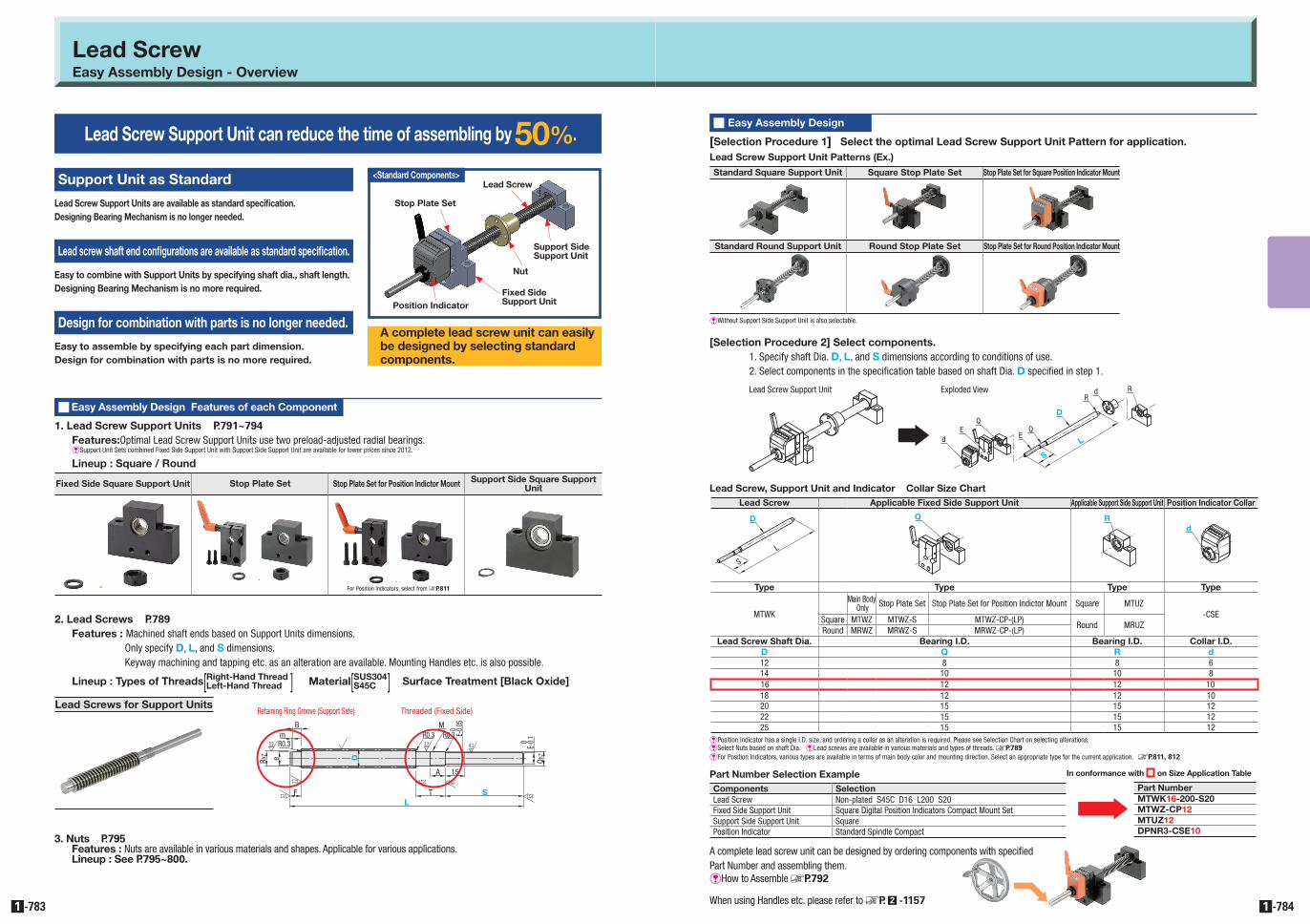
Lead Screw Support Unit can reduce the time of assembling by 50%.
Support Unit as Standard
Lead Screw Support Units are available as standard specification.Designing Bearing Mechanism is no longer needed.
Lead screw shaft end configurations are available as standard specification.
Easy to combine with Support Units by specifying shaft dia., shaft length.Designing Bearing Mechanism is no more required.
Design for combination with parts is no longer needed.
Easy to assemble by specifying each part dimension.Design for combination with parts is no more required.
A complete lead screw unit can easily be designed by selecting standard components.
Q Easy Assembly Design Features of each Component
Q Easy Assembly Design
Stop Plate Set
Support SideSupport Unit
Stop Plate Set
Lead Screw
Nut
Fixed SideSupport UnitPosition Indicator
[Selection Procedure 1] Select the optimal Lead Screw Support Unit Pattern for application.Lead Screw Support Unit Patterns (Ex.)
Standard Square Support Unit Square Stop Plate Set Stop Plate Set for Square Position Indicator Mount
Standard Round Support Unit Round Stop Plate Set Stop Plate Set for Round Position Indicator Mount
eWithout Support Side Support Unit is also selectable.
3.2 3.2 6.3
3.2
3.2 3.2 6.3
6.3SL
Q h7
TF
R0.3
B
Rh7
A 15
D
E-0.
10
E-0.0
5
R0.3 R0.3M
e
m
0
Retaining Ring Groove (Support Side) Threaded (Fixed Side)
<Standard Components>

-7851
A_0785-0786_F11-03_cENG
-7861
A_0785-0786_F11-03_cENG cENG 2nd
Lead ScrewLead Screws - Overview
Type Slide Screw Lead Screw Rolled Ball Screw Precision Ball Screw
Shape
Features
Simple feed and adjust mechanisms, etc. Made of stainless steel shaft and plastic nut. No-grease operation is possible.
Optimal for the case where thrust loads and high loadings exist.
Can be applied at reasonable costs when precision ball screw accuracies are not required.
Optimal for the case where high positioning and velocity accuracy are required.
App. Example Stoppers In/Out and Transfer pitch changeover Transfer pitch changeover Jacks, Feed Screw for Lathes Transfer Line Measurement Instruments
Allowable Rotational Speed Low Speed Medium Speed High Speed High Speed
Accuracy
Allowable Axial Load( ) is for Reference.
r(max540N)
P(max30000N)
G(max9960N)
G(max9960N)
Lead ScrewLead Screw Specifications / Technical Calculations
PV Value Graph
108
6543
2
10.80.60.50.40.3
0.2
0.5 0.8 1 2 3 4 5 6 7 8 10 20 30 40 50 80 100
1Steel (Lubrication) - Brass2Steel (No Lubrication) - Plastic
Cont
act P
ress
ure
P(N/
mm
2 )
Sliding Speed V (m/min)
1 2
QNuts for Lead Screw SpecificationsQFeed Screw ComparisonPart Number / Type
MTS##/Standard
MTSP##/ Compact
MTSJR/Pilot
MTSQR/Slotted Holes
MTRFR / RoHS Compliant
MTBLR/Anti-Backlash
MTSM##/ Lubrication-Free
MTSR##/ High Strength Plastic
MTSF##/ Plastic Type
P.795 P.795 P.795 P.795 P.796 P.796 P.797 P.798 P.798Allowable Dynamic Thrust (N)
8 1.5 1470 - - - - - - - -10 2 2550 2020 - - 2550 2600 2550 278 25512 2 3920 3140 - - 3920 3390 3920 428 39214 3 4900 3920 4900 4900 4900 - 4900 536 490
16 2 - - 6670 6670 6670 - - - -3 6670 5340 - - 6670 6290 6670 686 628
18 4 8720 - - - - - - 954 873
20 2 - - - - 10100 - - - -4 9810 7850 9810 9810 9810 9320 9810 1071 980
22 5 12360 9890 12360 12360 - - 12360 - -25 5 14220 11380 14220 14220 14220 - 14220 - 141228 5 17950 14420 17950 17950 17950 - 17950 - 176532 6 21080 16940 21080 21080 21080 - 21080 - 205036 6 25780 - - - - - 25780 - -40 6 33830 - - - - - 33830 - -50 8 40310 - - - - - - - -
QLead Screw Technical Calculations
Calculate 1 Contact Pressure P and 2 Sliding Speed V.Confirm that the cross point is located inside the lines in PV Graph
Determine conditions of use Axial Load, Speed
Temporarily select the Lead Screw Nut part number Lead Screw Nut Material
Calculate 3 Screw Efficiency j and4 Load Torque T Use This Tesult For Selecting Motors, etc.
NG
Lead Screw Nut Selection Procedure
In case of using MTSRW16 shaft, pitch 3 and MTSFR16 brass flanged nut when the axial load is 300N as rotational speed at 500min-1.
1Contact Pressure P (N/mm2)
P= x@= x9.8=0.44(N/mm2)FsFo
3006670
2Sliding Speed V (m/min)
V= x10-3= x10-3=22.8(m/min)π • d2 • n
cos(d)πx14.5x500cos(3°46')
When the PV Graph is viewed based on the calculated P and V values, the cross point V=22.8(m/min) when P=0.44(N/mm2) is located inside the line 1 on the PV Graph, thus it can be stated that no abnormal wear will occur.
Required Torque when using MTSRW16 shaft , pitch 3, and MTSFR16 brass (flanged nut.)
Also, in a case of calculating for the Load Torque T (N • cm) when the axial load is 300N.
3Screw EfficiencyJ
J= = =0.241-µtan(d)1+µ/tan(d)
1-0.21xtan(3°46')1+0.21/tan(3°46')
4Load Torque T (N • cm)
T= = =59.7(N • cm)FS • R2π • J
300x0.32πx0.24
Thread Shaft Nut Dynamic Friction Coefficient µ
Steel (Lubrication) Brass 0.21Steel (Non Lubrication) Polyacetal / PPS Resin with Sliding Property 0.13
QDynamic Friction Coefficient Reference Value
QLineup : Lead ScrewsLead Screw Type Shape Right-Hand Thread Left-Hand Thread Fine Pitch Right-Hand Thread Right and Left-Hand Thread Precision Right and Left-Hand Thread Page
Both Ends Stepped g g g g g P.801
One End Stepped / One End Double Stepped g g - g g P.803
One End Stepped / One End Double Stepped g - - - - P.805
Both Ends Double Stepped g g - - - P.807
Straight g g - g - P.808
QLead Screw Thread Geometry Standards (JIS Tr)HOC1.866P H1OA0.5P d22-Ø6.4(28)d1(Secondary Nut DOrdering Exampled D1Priced1
P
15° 15°30°
HH/
2H/
2H 1
H1/2
d1D 1
ord2
D 2orThreaded d
or D
Tapped
QLead Screw Accuracy StandardsItem Content
Allowable Dimension and Tolerance JISB0217 0218Screw Accuracy 7e GradeNut Accuracy 7H GradeSingle Pitch Error ±0.02Accumulated Pitch Error ±0.15/300mmShaft Maximum Runout See table belowLength Tolerance JIS B 0405 (Medium Class)
H=1.866P H1=0.5P d2=d-0.5Pd1=d-P D=d D2=d2 D1=d1
Thread d: O.D . d1: Root Dia. d2: Effective Dia.Tapped D: Root Dia. D1: I.D. d2: Effective Dia.
P: Pitch H1: Engage Height
E Pitch 3 of D Dimension 16, Pitch 5 of D Dimension 25 and Pitch 6 of D Dimension 40 conform to Tr Standard.
(20) (20)
D
• Runout Measurement Method
Calculate Contact Pressure P and Sliding Velocity V based on conditions of use to check that no abnormal wear will occur.Calculate cross point based on the calculated P and V values in PV Graph.When the cross point is located inside the line 1 or 2 in PV Value Graph, it can be stated that no abnormal wear will occur.
1Contact Pressure P (N/mm2)P= FS
FOx@
Fs : Axial Load (N)Fo : Allowable Dynamic Thrust (N) >> Nuts for Lead Screw SpecificationsThe thrust when the contact pressure acting on the screw shaft and nuts is 9.8 (0.98N)/mm2
@ : 9.8 (Brass), 0.98 (Resin)
2Sliding Speed V (m/min)V= π • d2 • n
cos(d)x10-3
d2 : Screw Shaft Effective Dia. >> Nuts for Lead Screw Specificationsd : Screw Shaft Lead Angle (Degree) >> Nuts for Lead Screw Specificationsn : Screw Shaft Revolution Frequency per Minute (min-1)
3Screw Efficiency jj= 1-µtan(d)
1+µ/tan(d)µ : Dynamic Friction Coefficientd : Screw Shaft Lead Angle (Degree)
4Load Torque T (N • cm)
T= FS • R2π • j
Fs : Axial Loadj : Screw EfficiencyR : Lead (cm)
QLead Screw Specifications
Shaft Dia. Pitch
Screw Shaft
Effective Dia.
Screw Shaft
Minor Dia. (MIN.)
Screw Shaft Lead Angle
Screw Shaft Runout (Max.)Shaft Overall Length
~125 126~200 201~315 315~400 401~500 501~630 631~800 801~1000 1001~1250 1251~1600 1601~20008 1.5 7.25 (5.9) 3°46' 0.1 0.14 0.21 0.27 0.35 - - -
- - -10 2 9 (7.2) 4°03'0.09 0.12 0.16 0.21 0.27 0.35 0.46 0.58
12 2 11 (9.2) 3°19'14 3 12.5 (10.1) 4°22'
0.09
0.11 0.13 0.16 0.2 0.25 0.32 0.42
- - -
162 15 (13.18) 2°25'
0.55 0.73 13 14.5 (12.1) 3°46'
18 4 16 (13.1) 4°33'-
202 19 (17.18) 1°55'4 18 (15.1) 4°03'
22 5 19.5 (16.1) 4°40'
- 0.09 0.11 0.13 0.16 0.19 0.23 0.3 0.38 0.5 0.6925 5 22.5 (19) 4°03'28 5 25.5 (22) 3°34'32 6 29 (24.5) 3°46'36 6 33 (28.5) 3°19'
- 0.11 0.11 0.11 0.13 0.15 0.17 0.22 0.27 0.34 0.4640 6 37 (32.5) 2°57'50 8 46 (40.4) 3°10'
Unit : mm
Calculation Example
Sha
ft D
ia.
Pit
ch
Calculation Example

-7871
A_0787-0788_F11-04_cENG
-7881
A_0787-0788_F11-04_cENG cENG 2nd
Lead Screw Application Examples
QApp. Example 2 Machine Name Sheet Steel Roll Base with Adjustment Mechanism
QApp. Example 1 Machine Name Slide Base Feed Mechanism for Reference Shoulder Adjusting
QLead Screw Application Examples
QSlide Screw Application ExampleWith a stainless steel thread shaft and a plastic nut, slide screws can be used without grease and are suitable for use with the screw feed mechanism in clean environments.Slide screws are low cost and offer smooth movements due to their excellent tribological properties.
QApp. Example 1 Machine Name Camera Inspection Unit
Lead Screw Shaft End Machining - Overview
QNotes on Selecting Alterations1 Specify an alteration position to be 2mm or more away from the stepped part. (See Diagram Note 1.)2 When adding multiple alterations, there must be 2mm or more clearance between each feature. (See Diagram Note 2.)3 When flat machining, wrench flats, square chamfering and keyway alterations are combined with each other, their orientations will be random. (See Diagram Note 3.)4 When two or more features are specified on a shaft, some alterations may not be possible due to their correlations.5 Do not specify multiple alterations in such a way that they overlap with each other in the rotating direction on the same shaft. (See Diagram Note 5.)
Square Chamfering Coarse TappingShaft End Dia. Square Machining Tap Dia.
6~10 5~8 311~14 8~10 3, 415~19 10~14 3, 4 , 520~25 14~20 3, 4 , 5 , 6 , 826~30 19~24 3, 4 , 5 , 6 , 8 , 1031~35 22~28 3, 4 , 5 , 6 , 8 , 10 , 1236~40 26~30 3, 4 , 5 , 6 , 8 , 10, 12, 16
Note1Specify an alteration portion to be 2mm or more away from the stepped part.
Note22mm or more is required for the clearance between multiple alterations.
Note3When the multiple alterations are combined each other, their orientations are random and thus, are not always aligned in a linear arrangement. (One example of this is shown on the diagram below.)
For Alterations A and B added to the same shaft, as shown on the diagram above, their orientations are random and thus, there are some cases where they are not aligned in a linear arrangement.
Note5Do not specify multiple alterations in such a way that they overlap with each other on the same shaft.(Any diagram as shown bellow is not acceptable.)
QOverlapped portion of Alterations A and B
Alteration Items Alterations Code Spec.
Flat MachiningFW FC(F#)
FY Shaf
t End
Dia
.min2 F#FVFQFRFEFC
Adds a flat on a shaft end. EWhen shaft end diameter ≤25, FY≤1.0Usage Used for a set screw flat when mounting a handle. EWhen shaft end diameter ≥26, FY≤2.0
Ordering Code FC5-FW10-FY1 E3≤FW≤200.5mm Increment EF#=0, or F#≥2EOnly one end of the shaft is machined
2 Flats Machining
SWSY
min2
SC(S#)
Shaf
t End
Dia
. S#SCSQSESRSV
2 flats (wrench flats) are machined on one end of the shaftUsage For wrench use
Ordering Code SC5-SW10-SY81mm IncrementEOnly one end of the shaft is machined
EWhen shaft end O.D. <15, SW≥ end O.D. -2EWhen 15≤ shaft end O.D. ≤25, SW ≥ end O.D. -3EWhen 30≤ shaft end O.D., SW≥ end O.D. -5E3≤SY≤20ES#=0, or S#≥2
Retaining Ring Groove
n
e
Shaft End LengthAC
(A#)
mShaf
t End
Dia
.
A#ACAQARAE
Adds a retaining ring groove on a shaft end.Usage For bearing mounting, etc.
Ordering Code AC13.30.1mm increment
E�AC (AQ, AR, AE) ≤ Shaft End Length-m-n For the m,n value, see the table on the right.
(For the m value, consider the tolerance. )
Shaft End Dia. e Tolerance m+0.14
0n Machining
LimitRetaining
Ring6
4+0.075
00.7
n≥1.2E-Shaped Retaining
Ring
78 59 6 0.9
10 9.6 0-0.09
1.15
n≥1.5 C-Shaped Retaining
Ring
12 11.5
0-0.11
14 13.415 14.316 15.217 16.220 19
0-0.21
1.3525 23.930 28.6
1.6535 33
40 38 0-0.25 1.9 n≥2
Coarse Tapping Sh
aft E
nd D
ia.
Shaf
t End
Dia
.MR (M#) MQ (M#)
Screw Dia.x2 Screw Dia.x2
M#MCMQMRMEMV
Adds a coarse threaded tapped hole on the shaft end.Usage Used for mounting threaded item (knobs, etc.)
Ordering Code MC24Select from table on the right.
XNot applicable to 4mm dia. shaftsE�When combined with an other alteratuion,
do not specify this alteration in such a way that the shaft thickness on the tapped part becomes less than 1mm.
Shaft End Dia. MC (M#): Tap Dia. Selection Range5 36 3
7, 8 3, 49, 10 3, 4, 5
11, 12 3, 4, 5, 613~15 3, 4, 5, 6, 816~18 3, 4, 5, 6, 8, 1019~24 3, 4, 5, 6, 8, 10, 1225~30 3, 4, 5, 6, 8, 10, 12, 1631~39 3, 4, 5, 6, 8, 10, 12, 16, 2040, 50 3, 4, 5, 6, 8, 10, 12, 16, 20, 24, 30
For Bearing NutThreaded for Bearing Nuts
M
BC
(B#)
Shaft
End D
ia.
B#BVBCBQBR
Cuts a thread on the shaft end.Usage For locking bearing nuts
Ordering Code BC20Select from table on the right.Nut Detail WP.1036XShaft end diameters applicable to 7, 9, 16 are not available.EB#�(Tap Length) ≤ Shaft End Dia. x 3EB#�(Tap Length) ≥ Pitch x 3EB#�(Tap Length) ≤ Shaft End Length - Pitch x 3
Shaft End Dia. MxPitch6 M 6x0.758 M8x1.010 M10x1.012 M12x1.014 M14x1.015 M15x1.017 M17x1.020 M20x1.025 M25x1.530 M30x1.535 M35x1.540 M40x1.5
Square Machining
Shaf
t End
Dia
.
3.2Shaft End Lengtht
W-0.1
-0.3 A
Z#ZCZQZEZRZV
Adds square chamfering on a shaft end.Usage For mounting handles, etc.
Ordering Code ZC12-W10-A8ESpecify ZC (Z#) as same as the end diameterW=Select from the table on the right, or specify in 1mm increment A=1mm IncrementE5≤A≤20EOnly one end of the shaft is machined
Shaft End Dia. W 1mm Increment Shaft End Dia. W 1mm Increment6, 7 5 6~10 5~88 6 11~14 8~109 7 15~19 10~1410 8 20~25 14~2012 9 10 26~30 19~24
14, 15 10 11 12 31~35 22~2816 11 12 13 36~40 26~3017 12 13 1420 14 15 1625 17~2030 21~2435 25~2840 29~30
Keyway
Cmin2 KC (K#)
3.2
1.6 b
Shaft
End D
ia.
1
r1
t 1
K#KCKQKVKEKR
Adds a keyway on a shaft end.Usage For handle mounting keyway use
Ordering Code KC8-C10KC (K#) and C: Specify in 1mm incrementEOnly one end of the shaft is machinedEC≤60,C≥t1EKC�(K#)≥2, or KC�(K#)=0E�When KC (K#)=0, keyway R will be eliminated on the end side.
Applicable Shaft End
Dia.
Keyway Dimensionb1 t1
r1Reference Dimension
Tolerance (N9)
Reference Dimension Tolerance
6 • 7 2 -0.004 -0.029
1.2
+0.10
0.08~0.168~10 3 1.8
11 • 12 40
-0.030
2.513~17 5 3
0.16~0.2518~22 6 3.5
23~30 8 0 -0.036
4+0.2
031~38 10 5
0.25~0.4039, 40 12 0
-0.043 5
C
EOrders can be placed without drawings by adding the Alteration Specifications listed below to the standard lead screw product part numbers. Procurement is quick with short lead time.
QConditions Applied to Lead Screws with Alterations for Combination of Square Chamfering and Tapping. EApplied to Lead Screws on P.803~807.
Contact BlockPress-fit Head
Press-fit Bearing Case Body
Slide Base Stopper Screw
Part A
Detail of A MTWK(Lead Screw Support Unit P.790)
Slide Base MTWZ(Lead Screw Support Unit P.791) AHLN100
(Five Spoked Handwheel P.Q2 -1157)
WSSB(Metal Washer P.Q2 -111)
MTUZ(Lead Screw Support SideSupport Unit P.792)
DNBB(Nut for Lead ScrewsBracket P.800)
MTSFR (Flanged Nut P.795)
• Applications
Used for transfer feeding, locating stoppers, and guiding of various workpieces.Adjustments are relatively small, but shock loads in axial direction are considered.In addition, the lead screw scheme is chosen for its low price.
• Selection Criteria
Lead Screw ShaftA lead screw shaft configured specifically for MISUMI Shaft Supports with a Keyway is selected.The configuration supports each end of the shaft with a bearing.
Lead Screw Support UnitsLead Screw Support Unit is selected for the fixed side of the shaft.Selected support unit has two radial bearings in preloaded arrangement.Selected since thrust loads can be supported.
Lead Screw Support UnitsA Shaft Support Unit for Lead Screws is selected for the shaft support side.Comes with two radial bearings in the set, and used as is.
Nuts for Lead ScrewsCommonly used Round Flanged Lead Screw Nut is selected.
Nut BracketsA Nut Bracket compatible with a lead screw nut is selected.
• Conditions of Use
1Applied Load 200N Material Mass : 300N2Setup Change-over Frequency Once a day for rod changes, etc.3Positioning Accuracy ±0.5mm4Stroke 150mm
PBR
Part A
Detail of A
MTWK (Lead Screw Support Unit P.789)
Sheet Inlet
Rolled Sheet Steel
MTWZ-CP(Lead Screw Support UnitStop Plate Set P.791)MTSMR (Flanged Lubrication-Free Nut P.797)
DPNR(Digital Position Indicators Compact P.812)
• Applications
Sheet steel roll's remaining O.D. is measured at set intervals, and the roll is raised accordingly with a lead screw.The lead screw feed amount is measured by a position indicator, instead of using a conversion table.
• Selection Criteria
Lead Screw ShaftA lead screw shaft configured specifically for MISUMI Shaft Supports with no R machining on the support side (Alteration RC) is selected.
Lead Screw Support UnitsLead Screw Support Unit is selected for the fixed side of the shaft.Selected since thrust loads can be supported, and a Digital Position Indicators Compact can be directly mounted.
Nuts for Lead ScrewsRound Flanged Lubrication-Free Lead Screw Nut is selected.Selected because the lubrication maintenance can be reduced to only once a year.
Position IndicatorsA Digital Position Indicators Compact is selected for lead screw feed distance measurements.
• Conditions of Use
1Applied Load 20kN2Maintenance Once a year3Positioning Accuracy 1~2mm4Stroke 150mm
HBK (Aluminum Knurled Handwheel P.Q2 -1159)
Camera
MSSRA (Slide Screw P.817)
235
255
• Applications
A slide screw is chosen for fine adjustability, and can be used without lubrication maintenance.
• Selection Criteria
Slide Screw ShaftOne End Stepped Type in SUS304 is selected.NutTribological resin nut is selected for zero grease requirement and good corrosion resistance.
• Conditions of Use
1Applied Load 50N2Setup Change-over Frequency Once a day for rod changes, etc.3Positioning Accuracy ±0.5mm4Stroke 100mm
Configuration comprised of Shaft Support Unit for Lead Screws, Lead Screw Shaft, and a Position Indicator.
Configuration comprised of Shaft Support Unit for Lead Screws, Stop Plate Set, Lead Screw Shaft, and a Position Indicator.
A slide screw is utilized as the Z axis.
1mm or more is required.
Other Alterations(Keyway)
Tapped Hole
2mm or more is required.
Alteration AAlteration B
Alteration A (Keyway)AlterationB (Set Screw Flat)
RotatingDirectionRotatingDirection
AlterationB (Keyway)Alteration A (Wrench Flats)
Orientation
2mm or more is required.
AlterationsStep
EOn the table below, the "#" portion of F# and so on will contain the V, Q, R, E or C code which indicates which shaft part to add alterations to.
ESpecify each dimension
ESpecify each dimension
ESpecify dimensions after A#
ESelect Tap Dia. after M#
ESpecify Tap Length after B#
ESpecify W and A dimensions after Z#
ESpecify each dimension after K#