Embed Size (px)
Citation preview

486 IEEE TRANSACTIONS ON MAGNETICS, VOL. MAG-17, NO, 1, JANUARY 1981
LCP HEATER THERMAL PERFORMANCE TEST RESULTS AND UNIQUE TEST TECHNIQUES
R. E. Bailey, E. H. Christensen General Dynamics Convair Division
San Diego, CA 92138
ABSTRACT The Large Coil Program (LCP) magnet requires integral heaters capable of normalizing conductor half-turns to simulate energy deposition. During a series of tests to determine the cryogenic ther- mal performance of our LCP conductor, we evaluated the relative thermal performance of two prototype heater installation methods which were tested using a unique heater power control circuit. The prototype heaters were installed in two LCP conductors which were part of a 15-conductor test array used during the conductor thermal performance testing. Results are given comparing the thermal perfor- mance of the two heaters, one installed with indium foil and the other “soldered” with Woods metal. The performance of the Woods metal installation agreed closely to the finite element model predicted con- ductor thermal response to fast, high-power heater pulses, both in maximum temperature rise and time characteristics of the rise and recovery. The sluggish thermal response o f the conductor with the cold-welded indium ribbon-secured heater demonstrated that in- timate thermal coupling of the heater elements to the conductor is mandatory. The heater control circuitry is described which was developed in support of this test and provided transient heater power durations down to 5 msec and at power inputs up to 3000 watts. A brief description also is given of the transient and steady-state data acquisition systems used as well as the interface between the heater control circuitry and the remote computer used to control the tran- sient testing.
I INTRODUCTION
An important design requirement dictated by Oak Ridge National Laboratory (ORNL) in their Large Coil Program (LCP) specifica- tionl was that the LCP coil must contain a number of half-turn con- ductor heaters which were to be designed to allow: 1) simulation of heat deposition due to friction, 2) medium-level heat input to deter- mine the cryostability margins of the coil during various operational modes and 3) low-level heat input to simulate nuclear irradiation coil heating. To determine if our coil design would meet these re- quirements, Convair developed a verification test2 of our LCP con- ductor’s thermal design and included provisions to verify our pro- totype heater design as part of this verification test.
The test array contained 15 conductors which were full-sized in cross-section but limited to a length of 1.07111 (42 inches) due the size of our experimental liquid helium test dewar. This 5 x 3 experimental conductor array (Fig. 1) contained four heated and instrumented test conductors. The test array was assembled in a fixture simulating the high field corner of our LCP magnet design (Fig. 2) . The array con- tained our proposed interturn and interlayer insulation designs, which were designed to channel the energy laden helium from the ver- tically oriented heated conductor toward the coil’s low field zone (Fig. 3). The experiment’s thermal performance portion was primari- Ly performed using the two internally heated conductors (A and B in Fig. 2), with the prototype LCP heaters serving as background heaters. The internal heaters of conductors A and B were t’abricated using nichrome foil in a printed circuit fashion laminated between 3 mil .Kapton films and then installed by bonding into the center plane of the conductors. Both heaters (Heater A was made from three
Figure 1. Fully Assembled Package Showing Support Devices.
Conductors clamped In
3-mrn thick snow fence layer-to.layer Insulation, 5Ooo open
Paperdoll turn-to-turn lnsulatlon
3-mm G- 10 ground lnsuiatlorl
10.8 cm - Package IS 1 .O7m long A. Three-segment heat transfer heater conductor;
6. Single. fuil-length heat transfer heater: C&D conductors have soldered cable & LCP %-turn heater, 11 remaining conductors solld copper
Figure 2. Test Package Simulates Coil Pack and Ventilation Paths near Inboard Corner of LCP Magnet.
Layer-to-layer insulation
Paperdoll interturn
Arrows indicate principal ventilation directions
Figure 3. Snowfence Interlayer and Paperdoll Interturn Insulations Combine to Provide Liberal 3 - 0 Ventilation.
0018-9464/81/0100-0486$00.75 0 1981 IEEE

48 7
longitudinally equal sections) had a total nominal power capability of 2500 watts. The prototype half-turn conductor heaters were fabri- cated from 23 gage (22 mil) nichrome wire, insulated with 2 mil Kap- ton. The heaters were in the shape of a hairpin loop, and had a total resistance of 9.1 ohms each. These heated conductors are labeled C and D in Fig. 2.
The nominal power requirements for the thermal performance heaters was 60 volts at 42 amperes, with the A heater divided into three heaters of 60 volts at 14 amps each. The nominal power re- quired for the two prototype LCP heaters was 150 volts at 16.6 amps each. This provided a 0.2 scale version of the full-sized heater of 13000 watts and 5.5m (216 inches) in length.
I1 TEST SETUP
Heater Installation
The LCP heater prototype installations (heaters C and D in Fig. 2) were made using two different techniques. A relatively high thermal conductivity coupling between the heating element and LCP conduc- tor was necessary. Initially, we planned to use a silver-filled epoxy as a potting agent to hold the heater wire in place in the bottom of the conductor slot, bearing on the superconductor cable as shown in Fig. 4. The silver-filled epoxy was felt to have good thermal properties, but a literature search3 revealed that it had low thermal conductivity compared to metals. Additional study showed that indium metal and a specific formulation of Woods metal had superior cryogenic ther- mal properties, so it was decided to install one of the prototype heaters with the indium in the form of a foil, and install the other us- ing a soldering method with the Woods metal (Indalloy 23; 50% Bi, 25% Pb, 12.5% Sn, and 12.5% Cd). Conductor C was selected for the indium installation. The foil first was formed into the slot and then the hairpin heater laid into the slot formed by the indium metal, which was then folded over the wire and pressed into place (Fig. 4). This method relied upon the cold-weld action between the indium foil and the solder-covered superconductor cable. The Woods metal installation was made in conductor D. It was found that a superior bond resulted from the process if the conductor was cleaned with a solvent and the heating controlled within a narrow temperature range.
31.'25 I 31.1 5 1 Super cable conduct o r b
Printed circuit
plane of heater on center
conductors A&B
'spaces
---f-
11 equal
10.41 9.91 1 t,Z'
Location of half-turn
I 3.35 3.10 P---
heater wire loop In conductors C&D
Dimensions in millimeters
Figure 4. Grade I Conductor With Superconducting Cable and Modifications for Heaters,
Heater Power Circuitry
The test plan called for many steady-state and transient tests, both for determining the conductor's thermal performance, for prototype LCP heater verification, and were to use various combinations for the interior-printed circuit heaters and the LCP prototype heaters. Some tests also required a heater power change during the test run.
T o achieve this capability a circuit similar to that shown in Fig. 5 was developed for each heater or heater section. To ensure that the power supply used for each heater did not cause a nonrectangular power waveform to occur during power application, an external load was first switched on, followed in two seconds by switching on the heater, while simultaneously removing the external load (Fig. 5). The exter- nal load resistances were chosen to be equal to the heater resistance values, so that the power switchover did not appear as a transient load to the power supply. Fig. 6 shows a typical waveform illustrating the flat-topped pulse resulting from this technique. This method also made possible the integration of energy input required for thermo- dynamic analysis, which would have been extremely difficult with a pulse characterized by excessive spikes or droop.
I Timing diagram 1 I Drive circuits
Load switching transistors, MJ1 0000
Figure 5. Typical Heater Control Circuitry.
PB No. 1 run 6
Figure 6. Typical Transient Run Heater Current Data.
The circuitry included manual heater switching controls for the steady-state tests and an interface to a HarrisM Computer which was used to remotely drive the heater switching circuitry during the tran- sient tests. The program input consisted of the times for each heater or external load to be switched on, and how long it was to remain on. This method permitted us to perform all of the transient tests in two fillings of the liquid helium test dewar, as each transient test used very little liquid helium and the rapid testing reduced the standby boiloff.
Instrumentation
The test package was instrumented with 18 gold plus 0.07% iron vs. copper thermocouples on the heated conductors. The thermocouples were formed by soldering the 35-gage copper wire to the 40 gage gold-iron wire. They were inserted in a small hole drilled in the sur- face of the copper conductor and secured by packing the hole with indium. The reference couple was made in a similar fashion, and mounted so as to be exposed to nonturbulent liquid. The copper and gold-iron wires leading from the conductor couples were heat-sunk into a groove in the copper conductor and held in place by a coat of a GE varnish, No. 7031. Each heater current and voltage, the dewar li- quid level, the dewar ullage pressure, and the helium temperature also were instrumented.

488
Due to the many test runs, each with its own recording require- ments, as well as the necessity for quickly changing the recording configuration to minimize helium boiloff during the downtime be- tween each test, it was decided to use a patchboard setup to permit fast and accurate changes to the recording setup. Each test run was grouped with others that shared similar recording requirements. Several patchboards were then prewired to suit these requirements.
During steady-state testing a Hewlett Packard Model 2578A data system (DYMEC) was used for data acquisition. This system had a resolution of 1 microvolt, which gave an average temperature resolution of 0.077 Deg K / p . Each heater power level was held for five seconds to achieve stability, then the data system sequentially measured and recorded all of the chosen data values. The total data channels recorded varied from 25-35 channels, depending on the test configuration. In addition to this primary data recording capability, an eight-channel strip chart recorder was used to allow the thermo- dynamic engineer to monitor certain selected data channels for real- time viewing.
The transient data was recorded using 14-channel wideband FM analog tape recorders. Two channels in each recorder were reserved for voice annotation and timecode recording. The heater and ther- mocouple signal conditioning system used differential amplifiers both for amplification and for signal isolation. These precautions were necessary because of the potential for common mode noise and ground loop voltages inherent in using the single ended circuitry of the FM tape recorders. During the steady-state testing, heater perfor- mance parameters were measured directly by the DYMEC voltmeter. A view of the complete test setup is shown in Fig. 7.
Figure 7. Complete Instrumentation Setup f o r Testing.
111 RESULTS
Data Reduction Methods The steady-state data was recorded on digital magnetic tape by the Hewlett Packard DYMEC Data System. A Varian V-72 computer
. was used to demultiplex, scale, and print the data. An example of this data printout is shown in Fig. 8. In addition, a magnetic tape of the scaled data was made to be used as input on a CYBER 72 computer to support further analysis. The transient data was played back on a strip chart recorder to ensure that the data events were properly recorded and to check on time correlation. The data runs then were digitized, scaled, and plotted as shown in Fig. 9. To achieve the desired thermal measurement response time, the digitization rate was 1 Khz. The analog filtering normally used to provide low-noise re- cording of microvolt signals could not be used in these transient tests, so an abnormal amount of noise was present in the data, particularly
‘ in the thermocouple data. During later analysis of this data, a digital filter was used to smooth the data and eliminate excessively large noise spikes caused by coupling of heater switching transients into the low-level instrumentation.
Test 5, SleadyStal
Time in
14 39 29.40 Hr, min. sec
14 40 16.80 14 40 29.10 14 40 40.00 14 40 51.60 14 41 2.90 14 41 16 20 14 41 28.10 14 41 42 10 14 41 54.40 14 42 9.40 14 42 24.40 14 42 39 30 14 42 53.60 14 43 19 10 14 43 39.00 14 43 51.30 1444 220 14 44 39.60 14 45 19 10
A Healers
Temp A I
-0 1283 0.1818 10239 0.8997 0.7712 03856 -0.1247 0.1918 1.3500 1 0239 1.0239 0 3856
-0.1335 0.1716 0.6427 0 771 2 0.6427 0.1285 -0.1422 0.1288 0.2571 0 3856 0.2571 0.2571
PSlD Della T WlCM 2 Delta T Delta T Della T Pressure Temp A4 I HI Flux L Temp A3 Temp A2
6.081 1 6.3787 7 1191 6.8996 0.2025 -0,1212 6.6019 6.8251
-0.1061 0 2562 9.3208 9 5292 8.9027 8.3385 -0 1144 0.2253 7 9134 8.1269 7.5523 6 9740 -0.1172 0.2141 7.4801 7.4801
11.9986 12 2708 13.01 90 12 81 50 0 3203 -0 0879 17 1947 17.4729 I84502 18.0996 04272 -0.0519 1 1.7260 -0.0828 0.3206 12 7469 13.0870 12.4068 8.9732 9 2514 10 0837 9.8764 0.2562 -0.1022 6 1555 6 8996 7.4801 7 4079 0.2140 -0.1 133 5.9295 6 3787 6 8251 6.8996
0.0000 0.0000 0.0000 0.0000 0.0000 -0,1346 0 1287 0.2571 0.3856 0 2571 0.1285 -0 1251 0.1716 0.6427 0.6427 0 3856 0.1285 -0,1239 0 1818 5.8519 58519 5.1543 4 7537 -0 1204 0.1924 6 4331 6.6019 5.7744 5 0767 -0.1172 0 2026
~ 0 . 1 5 4 8
o.oooo -0.1 576 O.OOOO i O.OOOO o 0000 o.0000
Figure 8. Typical Steady-State Run Data.
Liq level Percent
95 685C
98.1 540 97 5730
97.9090 98.1 200 97.7860 97 7050 97.5860
97.5080 97.51 60
97.7490
95.0040 96.3250
93.6950 92.9570 92.0190 92.2480 92.5300 91.8010 91 7190
Time, seconds
Figure 9. Temperature Responses to Heater Pulses Yield Data Deter- mining Transient Heat Flux.
Transient Data Analysis and Results
The effectiveness of a heater to simulate a fault energy deposition is related to speed with which the heat can be transferred from the ele- ment to the conductor. This heat is transferred faster the smaller the time Constant or thermal RC product in the heat flow path from ele- ment to conductor. An electrical insulator, which is also a thermal in- sulator, wraps around the electrical heating element. For one- dimensional slab heat flow:
R C a Z & x c x = Z - KA x2c
where: x = thickness of path
c = heat capacity of path material
K = thermal conductivity (low for insulating material)
A = heat flow element surface area
Geometrically a heater with large flow cross-section and thin in- sulation is the most effective. Obviously the printed circuit heaters with the flat elements and large surface areas are most efficient with the lowest time constants and provide the goal for performance of particular half-turn heaters. Practical considerations, however, led to insulated round-wire heaters for the LCP half-turn heaters which tend to be the least efficient for transferring heat. Moreover, to reduce the time constant and even to get the heat from the element to the conductor it is imperative to have intimate thermal coupling be- tween the insulated wire and the conductor. This implies potting the insulated wire to the conductor with high conductivity material.
489
Testing at the very low flux levels ( 0.01 w/cm2) corresponding to radiation heating for steady-state periods as long as 10 minutes hardly raised the conductor temperature and was nowhere near driv- ing the conductor beyond the differential temperature corresponding to peak steady-state nucleate boiling flux. At .the other extreme, the heaters were operated at full power (2500-2900 w/1.07m length) for periods of one second and at 75% of full power for periods of two seconds. The maximum conductor temperature experienced was 50K and the heater element was estimated to have risen to a temperature between 300 and 400K. This extreme exercising of the heaters was not detrimental and the heaters performed well on many runs after these high heat cycles. In the LCP the heaters would never be exercised at full power for pulse durations exceeding 100 ms.
IV CONCLUSIONS
The performance of the heater switching circuitry and computer in- terface was entirely satisfactory. The flat-topped heater power pulses that this circuitry provided made possible the thermodynamic analysis of the conductor pack performance. The concepts developed during this test are being used for the current ORNL design for the heater switching circuitry in the LCP Test Facility. These switching modules are being designed to handle up to 25 kw of heater power at voltages up to 1 kv.
The Woods metal soldered half-turn heater yields adequate tran- sient thermal response to simulate fault energy deposition densities corresponding to those asso6ated with predicted credible events such as frictional inputs. Good.thermal coupling of the heater to the cori- ductor is mandatory and the cold-welded indium ribbon securing, and any other system where the potting does not flow intimately around the heater wire is not acceptable. A 13 kw heater for a 5.5 meter long half-turn for LCP is an acceptable capacity and pulse durations of 15 to 25 ms will produce conductor temperature rises of 3 K in low field regions to 10 K in high field zones.
For a well-coupled heater, full-power pulses of 5 to 25 ms dura- tion were predicted to be necessary for deposition densities of 50 to 250 mj/cm3 corresponding to an estimated range of credible events for LCP. Fig. 9 shows a compariso,n of temperature response data between the best coupled printed circuit heater sandwiched in con- ductor A and the worst coupled half-turn wire heater secured in con- ductor C with indium ribbon. The poor thermal coupling and per- formance of the latter is manifest by the lesser temperature rise in response to twice the deposited energy.
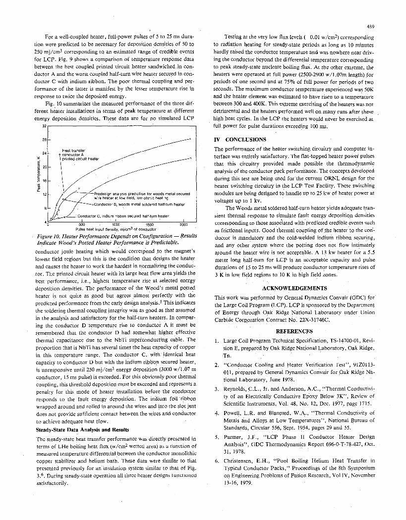
Fig. 10 summarizes the measured performance of the three dif- ferent hdater installations in terms of peak temperature at different energy deposition densities. These data are for no simulated LCP
28 -
24 - X
2 20- 2-
E 2
2
2 16- Y m
12 -
8 -
wire heater at low field, low ohmic heating
vL--”Conductor C, indium ribbon secured half-turn healer
4~ I i I I ’
500 1000 1500 2000 Pulse heat input density, mjlcm3 of conductor
Figure 10. Heater Performance Depends on Configuration -Results Indicate Wood’s Potted Heater Performance is Predictable.
conductor joule heating which would correspond .to the magnet’s lowest field regions but this is the condition that designs the heater and causes the heater to work the hardest in normalizing the conduc- tor. The printed circuit heater with its large heat flow area yields the best .performance, i.e., highest temperature rise at selected energy deposition densities. The performance of the Wood’s metal potted heater is not quite as good but agrees almost perfectly with the predicted performance from the early design analysis.5 This indicates the soldering thermal coupling ,integrity was as good as that assumed in the analysis and satisfactory for the half-turn heaters. In c,ompar- ing the conductor D temperature rise to conductor A it must be remembered that the conductor D had somewhat higher effective thermal capacitance due to the NbTi superconducting cable. The proportion that is NbTi has several times the heat capacity of copper in this temperature range. The conductor C, with identical heat capacity to conductor D but with the indium ribbon secured heater, is unresponsive until 250 mj/cm3 energy deposition (3000 w/l.07 m conductor, 15 m s pulse) is exceeded. For this obviously poor thermal coupling, this threshold deposition must be exceeded and represents a penalty for this mode of heater installation before the conductor responds to the fault energy deposition. The indium foil ‘ribbon wrapped around and rolled in around the wires and into the slot just does not provide sufficient contact between the wires and conductor to achieve adequate heat ffow.
Steady-State Data Analysis and Results
The steady-state heat transfer performance was directly presented in terms of LHe boiling heat flux (w/cm2 wetted area) as ;I tunction of measured temperature differential between the conductor monolithic copper stabilizer and helium bath. These data were similar to that presented previously for a n insulatiop system similar to that of Fig. 3.6. During steady-state operation all three heater designs tunctloncd satisfactorily.
ACKNOWLEDGEMENTS
This work was performed by General Dynamics Convair (GDC) for the Large Coil Program (LCP). LCP is sponsored by the Department of Energy through Oak Ridge National Laboratory under Union Carbide Corppration Contract No. 22X-31746C.
REFERENCES
1. Large Coil Program Technical Specification, TS-14700-01, Revi- sion E, prepared by Oak Ridge National Laboratory, Oak Ridge, Tn .
2. “Conductor Cooling and Heater Verification Test”, 91201 13- 01 1, prepared by General Dynamics Convair for Oak Ridge Na- tional Laboratory, June 1978.
3. Reynolds, C.L., Jr. and Anderson, A.C., :‘Thermal Conductivi- ty of an Electrically Conductive Epoxy Below 3K”, Review of Scientific Instruments, Vol. 48, No. 12, Dec. 1977, page 1715.
4. Powell, L.R. and Blanpied, W.A., “Thermal Conductivity of Metals and Alloys at Low Temperatures”, National Bureau of Standards, Circular 556, Sept. 1954, pages 29 and 55.
5. Parmer, J.F., “LCP Phase I1 Conductor Heater Design Analysis”, GDC Thermodynamics Report 696-0-T-78-427, Oct. 31, 1978.
6. Christensen, E.H., “Pool Boiling Helium Heat Transfer in Typical Conductor Packs,” Proceedings of the 8th Symposium on Engineering Problems of Fusion Research, Vol IV , November 13-16, 1979.