Embed Size (px)
Citation preview
LATERAL LOAD BEHAVIOR OF A POST-TENSIONED COUPLED CORE WALL
Steven Barbachyn1, Yahya C. Kurama2, Michael J. McGinnis3, Richard Sause4, Kristen A. Peterson5
ABSTRACT A 40%-scale multi-story reinforced concrete coupled core wall structure with unbonded post-tensioned coupling beams was recently tested under quasi-static reversed-cyclic lateral loading. This paper provides an overview of the design and experimental results from this test. Conventional reinforced concrete coupling beams in seismic regions are often designed with two intersecting groups of diagonal reinforcing bars crossing the beam-to-wall joints. The placement of these reinforcing bars is a major challenge during construction. The new system eliminates the diagonal reinforcement by using a combination of high-strength unbonded post-tensioning (PT) steel and top and bottom horizontal mild steel reinforcing bars crossing the beam-to-wall joints to develop the coupling forces. The coupled wall specimen that was tested represented the most critical bottom three stories of an eight story prototype structure, consisting of two C-shaped wall piers, six post-tensioned coupling beams (two beams at each floor because of the C-shaped piers), tributary post-tensioned slabs at each floor, and the foundation. The less critical upper stories of the prototype structure were simulated analytically to obtain the axial forces and overturning moments imposed at the top of the bottom three stories. In addition to a dense array of conventional sensors, the deformations of the test specimen were monitored using a total of 14 two and three-dimensional digital image correlation (DIC) sensors, providing near-full-field response data of the most critical regions of the structure in the wall piers, floor slabs, and coupling beams. Ultimately, the high-fidelity measured data from the test specimen will be used to validate seismic design procedures and modeling/prediction tools for post-tensioned coupled wall structures. These procedures and tools may form the basis for the future implementation of this novel structural system as “special” reinforced concrete shear walls in medium and high seismic regions of the U.S.
1Graduate Student, Dept. of Civil & Envir. Engin. & Earth Sciences, U. of Notre Dame, Notre Dame, IN 46556 2Professor, Dept. of Civil & Envir. Engin. & Earth Sciences, U. of Notre Dame, Notre Dame, IN 46556 3Associate Professor, Dept. of Civil Engin., U. of Texas at Tyler, Tyler, TX 75799 4Professor, Dept. of Civil & Environmental Engin., Lehigh U., Bethlehem, PA 18015 5Staff I-Structures, Simpson Gumpertz & Heger, Boston, MA 02453 Barbachyn S., Kurama Y., McGinnis M., Sause R., and Peterson K. Lateral Load Behavior of a Post-Tensioned Coupled Core Wall. Proceedings of the 10th National Conference in Earthquake Engineering, Earthquake Engineering Research Institute, Anchorage, AK, 2014.

Lateral Load Behavior of a Post-Tensioned Coupled Core Wall
Steven Barbachyn1, Yahya C. Kurama2, Michael J. McGinnis3, Richard Sause4, Kristen A. Peterson5
ABSTRACT
A 40%-scale multi-story reinforced concrete coupled core wall structure with unbonded post-tensioned coupling beams was recently tested under quasi-static reversed-cyclic lateral loading. This paper provides an overview of the design and experimental results from this test. Conventional reinforced concrete coupling beams in seismic regions are often designed with two intersecting groups of diagonal reinforcing bars crossing the beam-to-wall joints. The placement of these reinforcing bars is a major challenge during construction. The new system eliminates the diagonal reinforcement by using a combination of high-strength unbonded post-tensioning (PT) steel and top and bottom horizontal mild steel reinforcing bars crossing the beam-to-wall joints to develop the coupling forces. The coupled wall specimen that was tested represented the most critical bottom three stories of an eight story prototype structure, consisting of two C-shaped wall piers, six post-tensioned coupling beams (two beams at each floor because of the C-shaped piers), tributary post-tensioned slabs at each floor, and the foundation. The less critical upper stories of the prototype structure were simulated analytically to obtain the axial forces and overturning moments imposed at the top of the bottom three stories. In addition to a dense array of conventional sensors, the deformations of the test specimen were monitored using a total of 14 two and three-dimensional digital image correlation (DIC) sensors, providing near-full-field response data of the most critical regions of the structure in the wall piers, floor slabs, and coupling beams. Ultimately, the high-fidelity measured data from the test specimen will be used to validate seismic design procedures and modeling/prediction tools for post-tensioned coupled wall structures. These procedures and tools may form the basis for the future implementation of this novel structural system as “special” reinforced concrete shear walls in medium and high seismic regions of the U.S.
Introduction
Reinforced concrete (RC) coupled shear wall structures are commonly used for primary lateral load resistance in medium and high-rise buildings in regions of moderate and high seismicity. The typical coupled wall system consists of two or more vertical shear wall piers connected by relatively short, deep beams called coupling or link beams at the floor and roof levels. Properly designed and detailed coupled walls can provide large strength, stiffness, and energy dissipation under lateral loads; however, the design and construction of the coupling
1Graduate Student, Dept. of Civil & Envir. Engin. & Earth Sciences, U. of Notre Dame, Notre Dame, IN 46556 2Professor, Dept. of Civil & Envir. Engin. & Earth Sciences, U. of Notre Dame, Notre Dame, IN 46556 3Associate Professor, Dept. of Civil Engin., U. of Texas at Tyler, Tyler, TX 75799 4Professor, Dept. of Civil & Environmental Engin., Lehigh U., Bethlehem, PA 18015 5Staff I-Structures, Simpson Gumpertz & Heger, Boston, MA 02453 Barbachyn S., Kurama Y., McGinnis M., Sause R., and Peterson K. Lateral Load Behavior of a Post-Tensioned Coupled Core Wall. Proceedings of the 10th National Conference in Earthquake Engineering, Earthquake Engineering Research Institute, Anchorage, AK, 2014.
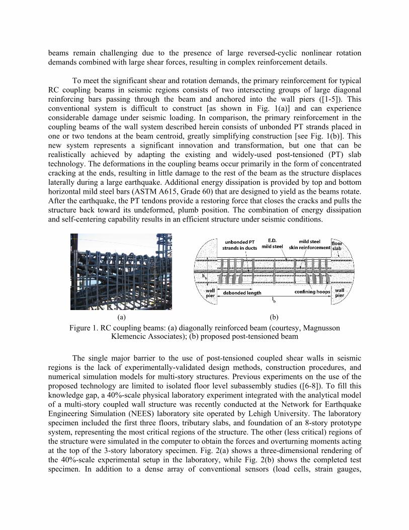
beams remain challenging due to the presence of large reversed-cyclic nonlinear rotation demands combined with large shear forces, resulting in complex reinforcement details.
To meet the significant shear and rotation demands, the primary reinforcement for typical RC coupling beams in seismic regions consists of two intersecting groups of large diagonal reinforcing bars passing through the beam and anchored into the wall piers ([1-5]). This conventional system is difficult to construct [as shown in Fig. 1(a)] and can experience considerable damage under seismic loading. In comparison, the primary reinforcement in the coupling beams of the wall system described herein consists of unbonded PT strands placed in one or two tendons at the beam centroid, greatly simplifying construction [see Fig. 1(b)]. This new system represents a significant innovation and transformation, but one that can be realistically achieved by adapting the existing and widely-used post-tensioned (PT) slab technology. The deformations in the coupling beams occur primarily in the form of concentrated cracking at the ends, resulting in little damage to the rest of the beam as the structure displaces laterally during a large earthquake. Additional energy dissipation is provided by top and bottom horizontal mild steel bars (ASTM A615, Grade 60) that are designed to yield as the beams rotate. After the earthquake, the PT tendons provide a restoring force that closes the cracks and pulls the structure back toward its undeformed, plumb position. The combination of energy dissipation and self-centering capability results in an efficient structure under seismic conditions.
The single major barrier to the use of post-tensioned coupled shear walls in seismic
regions is the lack of experimentally-validated design methods, construction procedures, and numerical simulation models for multi-story structures. Previous experiments on the use of the proposed technology are limited to isolated floor level subassembly studies ([6-8]). To fill this knowledge gap, a 40%-scale physical laboratory experiment integrated with the analytical model of a multi-story coupled wall structure was recently conducted at the Network for Earthquake Engineering Simulation (NEES) laboratory site operated by Lehigh University. The laboratory specimen included the first three floors, tributary slabs, and foundation of an 8-story prototype system, representing the most critical regions of the structure. The other (less critical) regions of the structure were simulated in the computer to obtain the forces and overturning moments acting at the top of the 3-story laboratory specimen. Fig. 2(a) shows a three-dimensional rendering of the 40%-scale experimental setup in the laboratory, while Fig. 2(b) shows the completed test specimen. In addition to a dense array of conventional sensors (load cells, strain gauges,
(a) (b)
Figure 1. RC coupling beams: (a) diagonally reinforced beam (courtesy, Magnusson Klemencic Associates); (b) proposed post-tensioned beam
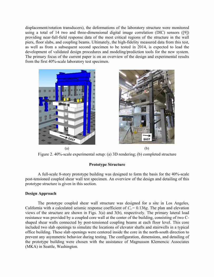
displacement/rotation transducers), the deformations of the laboratory structure were monitored using a total of 14 two and three-dimensional digital image correlation (DIC) sensors ([9]) providing near-full-field response data of the most critical regions of the structure in the wall piers, floor slabs, and coupling beams. Ultimately, the high-fidelity measured data from this test, as well as from a subsequent second specimen to be tested in 2014, is expected to lead the development of validated design procedures and modeling/prediction tools for the new system. The primary focus of the current paper is on an overview of the design and experimental results from the first 40%-scale laboratory test specimen.
Prototype Structure
A full-scale 8-story prototype building was designed to form the basis for the 40%-scale
post-tensioned coupled shear wall test specimen. An overview of the design and detailing of this prototype structure is given in this section. Design Approach The prototype coupled shear wall structure was designed for a site in Los Angeles, California with a calculated seismic response coefficient of Cs = 0.136g. The plan and elevation views of the structure are shown in Figs. 3(a) and 3(b), respectively. The primary lateral load resistance was provided by a coupled core wall at the center of the building, consisting of two C-shaped shear walls connected by post-tensioned coupling beams at each floor level. This core included two slab openings to simulate the locations of elevator shafts and stairwells in a typical office building. These slab openings were centered inside the core in the north-south direction to prevent any asymmetric behavior during testing. The configuration, dimensions, and detailing of the prototype building were chosen with the assistance of Magnusson Klemencic Associates (MKA) in Seattle, Washington.
(a) (b)
Figure 2. 40%-scale experimental setup: (a) 3D rendering; (b) completed structure

To determine the design forces for the prototype structure, the Equivalent Lateral Force (ELF) procedure from ASCE 7 ([10]) was used with an assigned response modification factor of R=6.0. The structure had a calculated fundamental period of T=0.74 s. The ELF procedure resulted in a design total base moment and total base shear force, which were then distributed to the components of the coupled wall structure by making a number of design selections. First, a coupling degree of 30% was chosen, meaning that 30% of the design base moment was to be carried by the coupling action between the two wall piers. This coupling moment was distributed to the post-tensioned coupling beams as a design shear force and corresponding moment at the beam ends, with the remaining base moment distributed evenly between the two wall piers. The reinforcement details of the wall piers and coupling beams were then selected to satisfy these design forces and achieve ductile behavior up to a maximum roof drift ratio of 3% for the 8-story structure. The specimen was intentionally designed not to have any significant over-capacity in force or displacement (e.g., no capacity reduction factor was used for axial-flexural design).
Figure 3. Full-scale prototype structure: (a) building plan; (b) building elevation; (c) wall pier base details; (d) 1st floor coupling beam end details
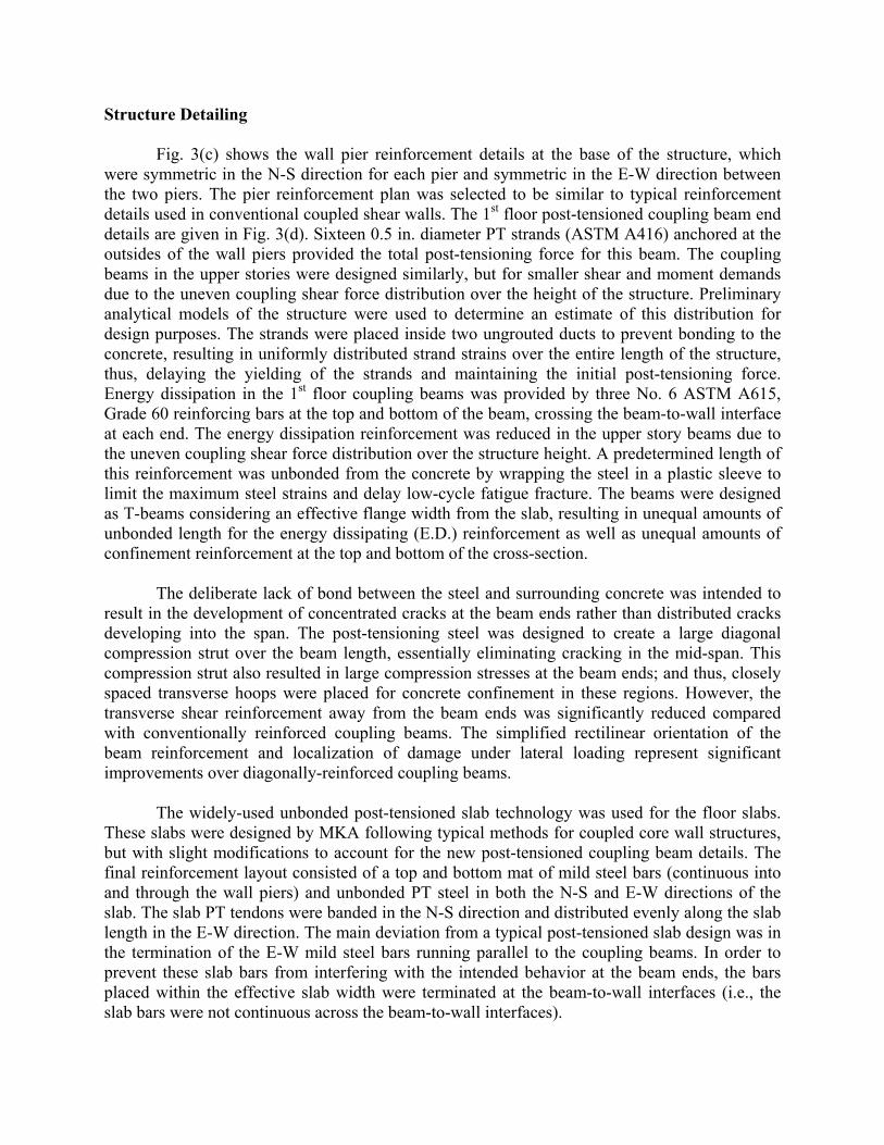
Structure Detailing
Fig. 3(c) shows the wall pier reinforcement details at the base of the structure, which were symmetric in the N-S direction for each pier and symmetric in the E-W direction between the two piers. The pier reinforcement plan was selected to be similar to typical reinforcement details used in conventional coupled shear walls. The 1st floor post-tensioned coupling beam end details are given in Fig. 3(d). Sixteen 0.5 in. diameter PT strands (ASTM A416) anchored at the outsides of the wall piers provided the total post-tensioning force for this beam. The coupling beams in the upper stories were designed similarly, but for smaller shear and moment demands due to the uneven coupling shear force distribution over the height of the structure. Preliminary analytical models of the structure were used to determine an estimate of this distribution for design purposes. The strands were placed inside two ungrouted ducts to prevent bonding to the concrete, resulting in uniformly distributed strand strains over the entire length of the structure, thus, delaying the yielding of the strands and maintaining the initial post-tensioning force. Energy dissipation in the 1st floor coupling beams was provided by three No. 6 ASTM A615, Grade 60 reinforcing bars at the top and bottom of the beam, crossing the beam-to-wall interface at each end. The energy dissipation reinforcement was reduced in the upper story beams due to the uneven coupling shear force distribution over the structure height. A predetermined length of this reinforcement was unbonded from the concrete by wrapping the steel in a plastic sleeve to limit the maximum steel strains and delay low-cycle fatigue fracture. The beams were designed as T-beams considering an effective flange width from the slab, resulting in unequal amounts of unbonded length for the energy dissipating (E.D.) reinforcement as well as unequal amounts of confinement reinforcement at the top and bottom of the cross-section.
The deliberate lack of bond between the steel and surrounding concrete was intended to
result in the development of concentrated cracks at the beam ends rather than distributed cracks developing into the span. The post-tensioning steel was designed to create a large diagonal compression strut over the beam length, essentially eliminating cracking in the mid-span. This compression strut also resulted in large compression stresses at the beam ends; and thus, closely spaced transverse hoops were placed for concrete confinement in these regions. However, the transverse shear reinforcement away from the beam ends was significantly reduced compared with conventionally reinforced coupling beams. The simplified rectilinear orientation of the beam reinforcement and localization of damage under lateral loading represent significant improvements over diagonally-reinforced coupling beams.
The widely-used unbonded post-tensioned slab technology was used for the floor slabs.
These slabs were designed by MKA following typical methods for coupled core wall structures, but with slight modifications to account for the new post-tensioned coupling beam details. The final reinforcement layout consisted of a top and bottom mat of mild steel bars (continuous into and through the wall piers) and unbonded PT steel in both the N-S and E-W directions of the slab. The slab PT tendons were banded in the N-S direction and distributed evenly along the slab length in the E-W direction. The main deviation from a typical post-tensioned slab design was in the termination of the E-W mild steel bars running parallel to the coupling beams. In order to prevent these slab bars from interfering with the intended behavior at the beam ends, the bars placed within the effective slab width were terminated at the beam-to-wall interfaces (i.e., the slab bars were not continuous across the beam-to-wall interfaces).

Experimental Program The construction and testing of the 40%-scale post-tensioned coupled shear wall specimen took place at the Real-Time Multi-directional (RTMD) Earthquake Simulation Facility, the Lehigh University NEES Equipment Site. All dimensions, reinforcement, and structure demands for the experimental specimen were reduced from the full-scale prototype building described in the previous section using the 40% scale factor. In some cases, the full-scale detailing did not scale exactly to a nominal reinforcement area or a regular dimension, requiring slight deviations from a perfectly-scaled structure. Despite these small deviations, the specimen still satisfied the scaled design demands.
The test specimen represented the most critical bottom three stories of the 8-story prototype structure. The upper five stories of the structure were simulated analytically in the computer using the DRAIN-2DX ([11]) structural analysis software. Since the post-tensioning of the coupled wall system is an integral part of the floor construction, the test sub-structure included a tributary portion of the slab at each of the three floors. In the analytical simulation, a 40%-scale model of the full 8-story structure was subjected to a reversed-cyclic lateral displacement history under the ELF profile from ASCE 7, combined with tributary gravity loads. The forces from the computer model were then applied to the physical structure using a total of 7 servo-controlled actuators and 4 hydraulic gravity jacks, simulating the behavior of the upper 5 stories of the 8-story building. The foundations were modeled as fixed.
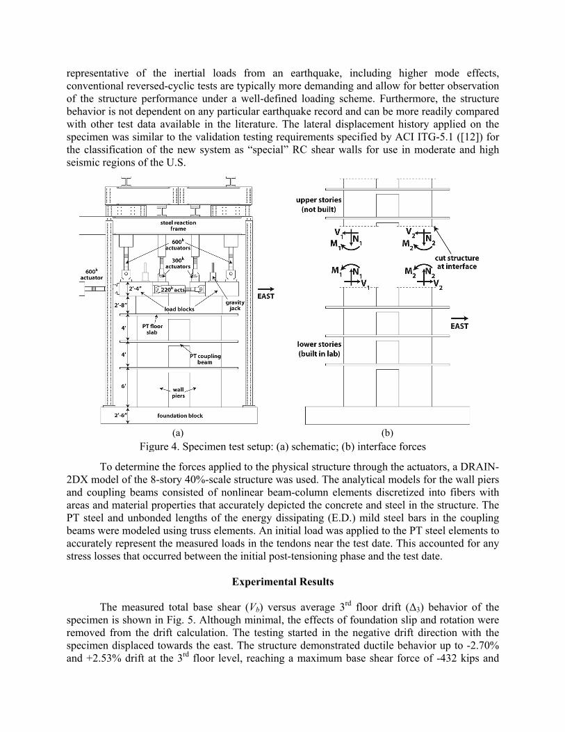
Fig. 4(a) shows a schematic of the test setup, including the steel reaction frame surrounding the structure. The forces from the actuators and gravity jacks were transferred to the specimen through a load block fixed to the top of each wall pier. These forces combine to impose the prescribed shear force, axial force, and overturning moment from the upper 5 stories at the top of each wall pier [see Fig. 4(b)], resulting in equilibrium between the physical and analytical sub-structures at the interface. In the horizontal direction, one servo-controlled hydraulic actuator was connected to the west loading block (at the top of the west wall pier, see Fig. 4) to simulate the lateral forces acting on the 3-story sub-structure from all of the stories above (i.e., 4th through the 8th stories). The ELF forces on the 1st, 2nd, and 3rd floors were also lumped at the west loading block level in a manner to result in the appropriate overturning moment at the base of the structure. Two additional actuators were placed between the east and west loading blocks (one on each of the north and south sides of the loading blocks) to appropriately distribute the applied shear force between the east and west wall piers. In the vertical direction, two servo-controlled hydraulic actuators were connected to the loading block at the top of each wall pier to control the axial force and bending moment boundary conditions at the top of the 3-story sub-structure, representing the forces transferred from the upper 4th through 8th stories. Additional hydraulic jacks placed on top of each wall pier simulated the tributary gravity loads on the structure, including the gravity loads applied on the upper stories (i.e., 4th through 8th stories). The load blocks were designed to perform as a rigid body with limited deformations while being subjected to the large forces during testing. Very little separation between the load blocks and the wall piers was observed during the experiment, validating the load block design.
The specimen was tested under a pseudo-static reversed-cyclic lateral displacement history applied in the direction of the coupling beams. While pseudo-dynamic tests are more
representative of the inertial loads from an earthquake, including higher mode effects, conventional reversed-cyclic tests are typically more demanding and allow for better observation of the structure performance under a well-defined loading scheme. Furthermore, the structure behavior is not dependent on any particular earthquake record and can be more readily compared with other test data available in the literature. The lateral displacement history applied on the specimen was similar to the validation testing requirements specified by ACI ITG-5.1 ([12]) for the classification of the new system as “special” RC shear walls for use in moderate and high seismic regions of the U.S.
To determine the forces applied to the physical structure through the actuators, a DRAIN-2DX model of the 8-story 40%-scale structure was used. The analytical models for the wall piers and coupling beams consisted of nonlinear beam-column elements discretized into fibers with areas and material properties that accurately depicted the concrete and steel in the structure. The PT steel and unbonded lengths of the energy dissipating (E.D.) mild steel bars in the coupling beams were modeled using truss elements. An initial load was applied to the PT steel elements to accurately represent the measured loads in the tendons near the test date. This accounted for any stress losses that occurred between the initial post-tensioning phase and the test date.
Experimental Results
The measured total base shear (Vb) versus average 3rd floor drift (Δ3) behavior of the specimen is shown in Fig. 5. Although minimal, the effects of foundation slip and rotation were removed from the drift calculation. The testing started in the negative drift direction with the specimen displaced towards the east. The structure demonstrated ductile behavior up to -2.70% and +2.53% drift at the 3rd floor level, reaching a maximum base shear force of -432 kips and
(a) (b)Figure 4. Specimen test setup: (a) schematic; (b) interface forces
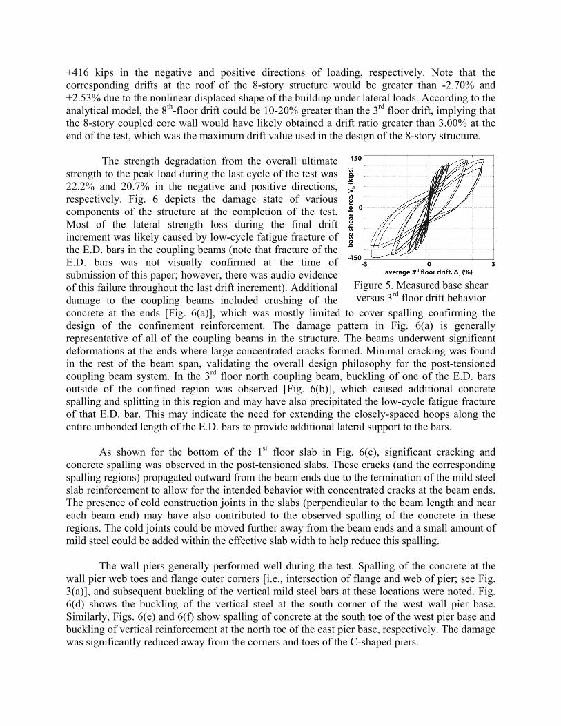
+416 kips in the negative and positive directions of loading, respectively. Note that the corresponding drifts at the roof of the 8-story structure would be greater than -2.70% and +2.53% due to the nonlinear displaced shape of the building under lateral loads. According to the analytical model, the 8th-floor drift could be 10-20% greater than the 3rd floor drift, implying that the 8-story coupled core wall would have likely obtained a drift ratio greater than 3.00% at the end of the test, which was the maximum drift value used in the design of the 8-story structure.
The strength degradation from the overall ultimate strength to the peak load during the last cycle of the test was 22.2% and 20.7% in the negative and positive directions, respectively. Fig. 6 depicts the damage state of various components of the structure at the completion of the test. Most of the lateral strength loss during the final drift increment was likely caused by low-cycle fatigue fracture of the E.D. bars in the coupling beams (note that fracture of the E.D. bars was not visually confirmed at the time of submission of this paper; however, there was audio evidence of this failure throughout the last drift increment). Additional damage to the coupling beams included crushing of the concrete at the ends [Fig. 6(a)], which was mostly limited to cover spalling confirming the design of the confinement reinforcement. The damage pattern in Fig. 6(a) is generally representative of all of the coupling beams in the structure. The beams underwent significant deformations at the ends where large concentrated cracks formed. Minimal cracking was found in the rest of the beam span, validating the overall design philosophy for the post-tensioned coupling beam system. In the 3rd floor north coupling beam, buckling of one of the E.D. bars outside of the confined region was observed [Fig. 6(b)], which caused additional concrete spalling and splitting in this region and may have also precipitated the low-cycle fatigue fracture of that E.D. bar. This may indicate the need for extending the closely-spaced hoops along the entire unbonded length of the E.D. bars to provide additional lateral support to the bars.
As shown for the bottom of the 1st floor slab in Fig. 6(c), significant cracking and concrete spalling was observed in the post-tensioned slabs. These cracks (and the corresponding spalling regions) propagated outward from the beam ends due to the termination of the mild steel slab reinforcement to allow for the intended behavior with concentrated cracks at the beam ends. The presence of cold construction joints in the slabs (perpendicular to the beam length and near each beam end) may have also contributed to the observed spalling of the concrete in these regions. The cold joints could be moved further away from the beam ends and a small amount of mild steel could be added within the effective slab width to help reduce this spalling.
The wall piers generally performed well during the test. Spalling of the concrete at the wall pier web toes and flange outer corners [i.e., intersection of flange and web of pier; see Fig. 3(a)], and subsequent buckling of the vertical mild steel bars at these locations were noted. Fig. 6(d) shows the buckling of the vertical steel at the south corner of the west wall pier base. Similarly, Figs. 6(e) and 6(f) show spalling of concrete at the south toe of the west pier base and buckling of vertical reinforcement at the north toe of the east pier base, respectively. The damage was significantly reduced away from the corners and toes of the C-shaped piers.
Figure 5. Measured base shear versus 3rd floor drift behavior

(a) (b) (c)
(d) (e) (f)
Figure 6. Specimen damage: (a) 2nd floor south coupling beam; (b) E.D. bar buckling in 3rd floor north coupling beam; (c) bottom of 1st floor slab; (d) south corner of west wall pier base;
(e) south toe of west wall pier base; (f) north toe of east wall pier base
Ongoing and Future Work
Design of the second post-tensioned coupled core wall specimen is currently underway. The new design will include improvements to the existing design method, particularly addressing the buckling of the E.D. bars by extending the closely-spaced hoops along the entire unbonded length of the bars. Other specimen changes may include altering the aspect ratio of the coupling beams, modifying the slab and wall pier base reinforcement details, and vertical post-tensioning of the wall piers. More information can be found at http://ptcoupledwalls.nd.edu.
Summary
The testing of a novel post-tensioned coupled core wall structure was recently completed. Overall, the structure performed as predicted and validated the design approach. Strength loss during the final cycles of the test was likely caused by low-cycle fatigue fracture of the E.D. bars in the coupling beams. Additional damage occurred in the form of localized concrete cracking and spalling at the beam ends, cracking and spalling of the slab concrete, and concrete spalling and vertical bar buckling at the toes and corners of the wall pier bases. The experimental results demonstrated the advantages of post-tensioned coupled walls and may ultimately form the basis for the future implementation of this structural system as “special” reinforced concrete shear walls in medium and high seismic regions of the U.S.
Acknowledgments
This project is a collaborative effort that includes the University of Notre Dame, the University of Texas at Tyler, and Lehigh University. The research is funded by the National

Science Foundation (NSF) under Grant No. CMMI 1041598 as a part of the “George E. Brown, Jr. Network for Earthquake Engineering Simulation (NEES) Research (NEESR).” This award is a part of the National Earthquake Hazards Reduction Program (NEHRP). Support of the NSF Program Director Dr. J. Pauschke is gratefully acknowledged. At the University of Texas at Tyler, students M. Lisk and M. Holloman worked on the development of the multiple DIC sensor protocol. At the Lehigh University NEES equipment site, laboratory staff (C. Bowman, P. Bryan, D. Fritchman, T. Maurullo, G. Novak, and E. Tomlinson), faculty members (S. Pakzad and J. Ricles), graduate students (M. Tillotson and K. Kazemibidokhti), and undergraduate students (A. Breden, M. Davis, F. Tao, E. Salazar, C. Fallon, and K. Brinkhoff) worked on the construction, instrumentation, and testing of the coupled wall specimen. The design of the test specimen was conducted in collaboration with practicing engineers from Magnusson Klemencic Associates (D. Fields, A. Haaland, and J. Mouras). The contributions of K. Bondy, Consulting Structural Engineer, to the project are also acknowledged. The concrete used to construct the test specimen was donated by Essroc Italcementi Group, the PT anchors were donated by Hayes Industries, Ltd., the PT strand was donated by Sumiden Wire Products Corporation (SWPC), and the formwork was donated by A.H. Harris & Sons, Inc. Additional material donations were made by Dayton Superior and Casilio Concrete. The findings, conclusions and/or recommendations expressed in this paper are those of the authors and do not necessarily represent the views of the individuals or organizations noted above.
References 1. Barney, G., Shiu, K., Rabbat, B., Fiorato, A., Russell, H., and Corley, W., “Earthquake Resistant Structural
Walls – Tests of Coupling Beams,” Construction Tech. Lab. Report, Portland Cement Assoc., January 1978.
2. Tassios, T., Moretti, M., and Bezas, A., “On the Behavior and Ductility of Reinforced Concrete Coupling Beams of Shear Walls,” ACI Structural J., 93(6), 1996, 711-720.
3. Bristowe, S., “Seismic Response of Normal and High Strength Concrete Members,” Ph.D. Dissertation. Civil Engineering and Applied Mechanics, McGill U., Montreal, Canada, 2000.
4. Galano, L. and Vignoli, A., “Seismic Behavior of Short Coupling Beams with Different Reinforcement Layouts,” ACI Structural J., 97(6), 2000, 876-885.
5. Canbolat, B., Parra-Montesinos, G., and Wight, J., “Experimental Study on Seismic Behavior of High-Performance Fiber-Reinforced Cement Composite Coupling Beams,” ACI Structural J., 102(1), 2005, 159-166.
6. Weldon, B. and Kurama, Y., “Nonlinear Behavior of Precast Concrete Coupling Beams,” J. of Structural Engineering, 133(11), 2007, 1571-1581.
7. Weldon, B. and Kurama, Y., “Experimental Evaluation of Post-Tensioned Precast Concrete Coupling Beams,” J. of Structural Engineering, 136(9), 2010, 1066-1077.
8. Weldon, B. and Kurama, Y., “Analytical Modeling and Design Validation of Posttensioned Precast Concrete Coupling Beams for Seismic Regions,” J. of Structural Engineering, 138(2), 2012, 224-234.
9. McGinnis, M., Barbachyn, S., and Kurama, Y., “Application of Multiple Digital Image Correlation Sensors in Earthquake Engineering,” 10th National Conference in Earthquake Engineering, Anchorage, AK, 2014.
10. ASCE/SEI 7-10, “Minimum Design Loads for Buildings and Other Structures,” American Society of Civil Engineers, Reston, Virginia, 2010.
11. Prakash, V., G.A. Powell, and Campbell, S., “DRAIN-2DX Base Program Description and User Guide,” Department of Civil Engineering, University of California, Berkeley, California, 1993.
12. ACI, “ACI ITG-5.1-07 Acceptance Criteria for Special Unbonded Post-Tensioned Precast Structural Walls Based on Validation Testing and Commentary,” ACI Innovation Task Group 5, 2007.