Embed Size (px)
Citation preview

Laser remote-sensing system analysisfor search and rescue
Christopher T. Field and Pamela S. Millar
We develop a general model of a laser remote-sensing system for search and rescue using targets markedwith fluorescent dye. The dye fluoresces at a longer peak wavelength than the incident radiation,enabling a dye-covered target to be distinguished from the unshifted ground echo by the search system.The principal result is a simple expression derived for the average laser power required to search at aparticular rate given a required ground energy density. A similar expression is applicable to imaginglidar systems. The example system shown indicates that active probing for lost planes may be practical.
OCIS codes: 280.3420, 280.0280, 160.2540.
1. Introduction
Current search methods for downed airplanes useremote detection of an emergency locator transmitter~ELT! and passive optical remote sensing. The ELTis a radio designed to transmit in response to a ca-tastrophe, in particular a major jolt indicative of anaccident. Installation of ELT’s in general aviationaircraft was mandated by Congress in the 1970’s.Updated, more-reliable ELT’s are now available;however, because installation is voluntary, adoptionis likely to be slow.1 Unfortunately because of poormaintenance or damage from a crash, the old ELT’soperate in less than 25% of all aircraft crashes.2Search efforts then resort to passive optical detectionin which a person uses ambient light to look for adowned plane. Darkness and fatigue reduce searcheffectiveness. According to Warren Vest, Director ofFlight Operation for the Maryland Civil Air Patrol,the current best probability of detection of a downedplane is less than 30%.3 Typical values of detectionare 15–20%, and four, six, or even eight overflightsare required before searchers can state that the prob-ability is less than 25% that a downed plane is in aparticular area.
The objective of this study is to assess the feasibil-
C. T. Field is with the Department of Electrical Engineering,U.S. Naval Academy, Annapolis, Maryland 21402. His e-mailaddress is [email protected]. P. S. Millar is with the LaserRemote Sensing Branch, NASA Goddard Space Light Center, MS924, Greenbelt, Maryland 20771. Her e-mail address [email protected].
Received 8 June 1998; revised manuscript received 11 January1999.
2586 APPLIED OPTICS y Vol. 38, No. 12 y 20 April 1999
ity of using a laser remote-sensing instrumentmounted on a small Civil Air Patrol airplane to locatedowned aircraft or distressed watercraft marked witha material that emits a signature that is distinct fromthe transmitter and background radiation. We con-sider two target cases based on fluorescent dye. Ageneral model of a remote-sensing system that can beused to determine system parameter requirementsfor various search and rescue situations is developed.An alternative system using retroreflectors is beingdeveloped by Daedalus Enterprises Inc.4
Search areas can range from densely wooded for-ests to open sea and from day to night searches.
2. Background
The dye fluorescein sodium salt is commonly used bymilitary pilots downed in the ocean to assist daylightrescue. After being downed, the pilot disperses theorange dye in the water. The dye typically spreadsout to a patch several tens of meters across. Duringdaylight, the patch can be seen easily from a searchaircraft or helicopter. Night search operation, how-ever, is not effective because of the lack of sunlight.
In the early 1970’s Richard Hughes of the U.S.Naval Weapons Center noted that the dispersed seamarker is a laser dye and glows bright orange whenilluminated by pulsed UV light from a nitrogen ~N2!laser at 337 nm. This bright orange glow made itpossible to locate a downed pilot at sea at night. Aremote-sensing system was proposed that would scana laser beam across the sea and use a photodetectorwith a bandpass filter centered at the expected fluo-rescence peak. The spectral width of the fluores-cence is between 40 and 100 nm. A prototypesystem was built5,6 and a patent was issued.7 How-

ncrssep2d
c
wlmmcTptgautn
sssdb
D
ever, interest faded, most probably because of theimmature laser and sensor technology that was avail-able in the 1970’s and because of poor system perfor-mance in fog and rain.
With the advancements of lasers, dyes, and im-proved sensors, remote-sensing systems for searchand rescue are more feasible today. Nabil Lawandy,of Spectra Sciences Corporation and Brown Univer-sity, proposed an extension of this idea by incorpo-rating a laser dye in ordinary white paint. Thismixture, when illuminated by a strong laser pulse,will not only fluoresce but will exhibit stimulatedemission8,9 in which all the dye output energy is con-tained in a small optical bandwidth, typically 5 nm,that is red-shifted from the pump-laser wavelength.In a remote-sensing system a narrow optical band-pass filter can be used to block reflected pump lightand most of the solar-generated background light.Ideally only surfaces marked with fluorescent paintwill emit optical radiation that passes through thereceiver bandpass filter; however, some solar photonswill also be detected. Currently, laser pulses of 3–10mJycm2 are required for spectral narrowing of theemission, which is approximately 4 orders of magni-tude higher than eye-safe levels for visible pumpwavelengths. However, as shown below, eye safetyis not the most stringent limit on pump energy den-sity.
When considering the fluorescence or stimulatedemission of dyes for search and rescue application,the following conditions have been set for a feasiblesystem. An automated search and rescue systemshould perform better than the current visual searchmethod. The system should be usable during dayand night. It must provide a significantly higherprobability of detection than current methods withsearch speeds and ground coverage that is compara-ble to or better than the current values of around 180km2yh with approximately 50% of the ground illumi-
ated by laser light. It should be usable under mostonditions in which planes can be flown. It must notequire more electrical power than provided on themall planes used by the Civil Air Patrol. Theingle-engine planes have approximately 800 W ofxcess electrical power at night and 1.5 kW of excessower in the daytime. The twin-engine planes have.5 and 11 kW excess electrical power at night andaytime, respectively.3Before exploring the details of the system, we re-
view the eye-safe limits for airborne laser systems.
3. Eye Safety Limits
An important condition of this system is that thepump beam incident on the ground not exceed eye-safe limits that were established assuming thatsomeone may look directly into the laser beam. Thelimits depend on the wavelength of the incident en-ergy and exposure time. For most airborne pulsedlaser systems the exposure time is the duration of onepulse. The calculation of safe intensity levels iscomplex and is described in detail in Ref. 10. How-ever, the results for direct exposure to a single short
pulse can be summarized as follows. For wave-lengths shorter than 400 nm the maximum permittedexposure ~MPE! is 3 mJycm2. For wavelengths be-tween 400 and 1400 nm, the MPE drops to 0.5 mJym2. For wavelengths longer than 1400 nm, the
MPE increases to 10 mJycm2. We show in Sections4–5 that even in the visible region, the eye-safe limitis a less restrictive limit than the average laser powerlimit for reasonable search rates.
Binocular and monocular optics with 50-mm objec-tive apertures are common. These have approxi-mately 50 times the light-gathering power of theeye.10 For the search and rescue system to be eyesafe when viewed through 50-mm optics, the MPEmust be lowered to 9.8 nJycm2 for visible light.
4. Mathematical Model
A mathematical model for determining the effective-ness of a laser remote-sensing search method hasthree major statistical components: the probabilityof a target being visible to the search plane, the prob-ability of correct detection of a visible target illumi-nated by a laser beam, and the probability that alaser beam will illuminate a potentially visible tar-get. The probability of a target being visible de-pends on the object size and the size distribution ofholes in the plant canopy as applied in the case ofwooded areas. The probability of correct detectionof an illuminated visible target depends on the sta-tistics of optical detection and the background lightlevel. This is the major thrust of our study. Theprobability of target illumination is quite variable asit depends on the laser beam size, the fraction ofground illuminated by the laser ~ground coverage!, as
ell as the target size. For example, 1-m-diameteraser spots spaced 2 m apart are guaranteed to illu-
inate an intact plane visible from above but mayiss a standing person, whereas 1-cm spots spaced 2
m apart would illuminate the plane and the person.he probability of target illumination is highly un-redictable because the laser beam size will vary withhe aircraft altitude above the ground, the effectiveround coverage of the laser depends on plant densityt the target site, and the target size will be somenknown function of how the plane crashed. Forhese reasons the probability of target illumination isot covered by this research.Figure 1 shows the system configuration with the
ystem parameters described in Table 1 with the re-ulting derived quantities given in Table 2. Aearch plane flies at altitude Rp with velocity Vp. Aownward-directed pulsed laser beam ~the pumpeam! with wavelength lp is swept perpendicular to
the flight path by a rotating mirror. A remote-sensing system using this approach is described inRef. 11. Each pump-laser pulse is assumed to havea top-hat intensity distribution and illuminates anarea Ap with constant energy density EG. The scanmirror also sweeps the field of view ~FOV! of aphoton-counting detector that detects light from theilluminated area. Only light within a range lr 6
lry2 centered on the target fluorescence peak lr
20 April 1999 y Vol. 38, No. 12 y APPLIED OPTICS 2587
rttt
ta
1er
P
Table 2. Derived System Parameters using the Values in Table 1
n
2
passes through an optical bandpass filter to the de-tector. If the target is present in the illuminatedarea, a small fraction hs of the pump is absorbed,eradiated by fluorescence, and collected by the de-ector system. Whether or not a target is present,he detector also collects nn noise photons from scat-ered sunlight and plant fluorescence.
Based on criteria outside the scope of this paper,he system designer must specify an acceptable prob-bility of miss PM and probability of false alarm PF.
We selected PF 5 PM 5 1029 as values for the inher-ent photon-limited performance. The actual systemperformance will be degraded by unmodeled param-eters. A pulse rate of 10,000 shotsys yields 3.6 3 107
shotsyh. A false-alarm rate of 1029 yields 3.6 3022 false alarms per hour or one false alarm forvery 27 h of searching. Higher pulse rates wouldequire a lower probability of false alarm to maintain
Fig. 1. Search model geometry. Plane at altitude Rp flies withspeed Vp. The pump has full-angle divergence 20p and illumi-
ates the ground area Ap.
Table 1. Assumed System Parameters
Description Symbol Value
Search speed Ss 180 km2yhGround coverage CF 100%Plane altitude Rp 1 kmScan angle umax 630 degPlane speed Vp 160 kmyh
~100 miyh!
Pump wavelength lp 532 nmPulse rate f 10 kHzAtmospheric trans-
mission ~one way!hatm 70%
Ground albedo r 50%
Target conversion hBW 10%Receiver wavelength lr 600 nmReceiver bandwidth Dlr 10 nmReceiver radius Rr 10 cmReceiver efficiency hD 10%Receiver field of
viewufov 3 mrad
Observation window Dtr 100 nsFalse-alarm proba-
bilityPF 1029
Miss probability PM 1029
588 APPLIED OPTICS y Vol. 38, No. 12 y 20 April 1999
approximately one false alarm per day. The actualfalse-alarm rate is likely to be higher because of Sunglint and plant fluorescence. Although the systemdesigner could decide that a higher false-alarm rate isacceptable, PF 5 1028 results in one false alarm every2.7 h which seems too high for the inherent ~perfectsystem! false-alarm rate. A probability of miss of1029 implies that in one billion passes over the target,only one miss is likely. The actual miss probabilitywill likely be much higher because of factors not in-cluded in this model such as target visibility andatmospheric effects.
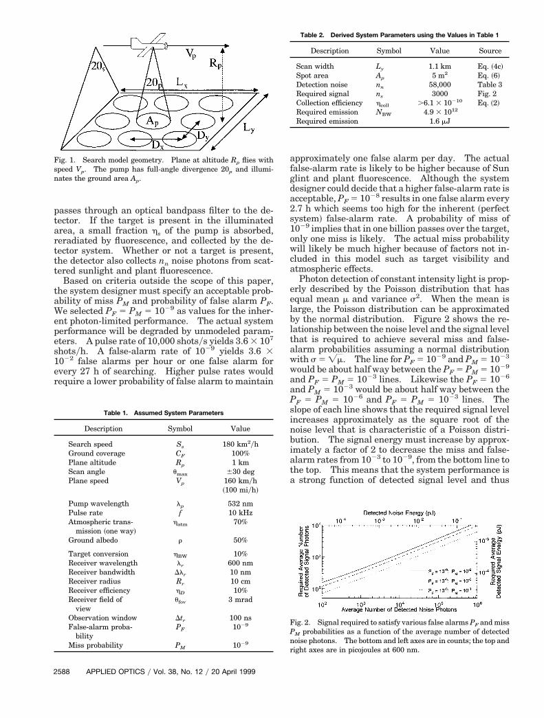
Photon detection of constant intensity light is prop-erly described by the Poisson distribution that hasequal mean m and variance s2. When the mean islarge, the Poisson distribution can be approximatedby the normal distribution. Figure 2 shows the re-lationship between the noise level and the signal levelthat is required to achieve several miss and false-alarm probabilities assuming a normal distributionwith s 5 =m. The line for PF 5 1029 and PM 5 1023
would be about half way between the PF 5 PM 5 1029
and PF 5 PM 5 1023 lines. Likewise the PF 5 1026
and PM 5 1023 would be about half way between thePF 5 PM 5 1026 and PF 5 PM 5 1023 lines. Theslope of each line shows that the required signal levelincreases approximately as the square root of thenoise level that is characteristic of a Poisson distri-bution. The signal energy must increase by approx-imately a factor of 2 to decrease the miss and false-alarm rates from 1023 to 1029, from the bottom line tothe top. This means that the system performance isa strong function of detected signal level and thus
Fig. 2. Signal required to satisfy various false alarms PF and missM probabilities as a function of the average number of detected
noise photons. The bottom and left axes are in counts; the top andright axes are in picojoules at 600 nm.
Description Symbol Value Source
Scan width Ly 1.1 km Eq. ~4c!Spot area Ap 5 m2 Eq. ~6!Detection noise nn 58,000 Table 3Required signal ns 3000 Fig. 2Collection efficiency hcoll .6.1 3 10210 Eq. ~2!Required emission NBW 4.9 3 1012
Required emission 1.6 mJ

a
i
l
Table 3. Detected Noise Photon Countsa Table 4. Pump Energy Densitya
system parameters. Therefore it is important thatthe values selected for analysis be accurate or muchlower than actually needed.
The photon noise level caused by solar or lunarbackground light can vary more than 5 orders of mag-nitude depending on solar angle.12 Table 3 showsthe expected number of detected solar photons as afunction of the number of Earth atmospheres throughwhich the sunlight is propagating. At sea level un-der clear skies when the Sun is directly overhead, theair mass is 1 ~ma 5 1!, whereas the air mass increasesto 2 ~ma 5 2! when the Sun has dropped to 60 deg.Above the atmosphere the air mass is 0 ~ma 5 0!. Athigh altitude with the Sun directly overhead, thebackground photon noise would be between ma 5 0nd ma 5 1. Under a full moon directly overhead,
0.2 noise photons are expected, yielding a total rangegreater than 5 orders of magnitude. The noise levelis relatively constant between laser shots so the re-ceiver can estimate the background noise level bymeasuring the detector output between receivedpulses and set the threshold appropriately. Assum-ing ma 5 1 at 600 nm, from Table 3, the backgrounds nearly 6 3 104 photons and from Fig. 2 the receiver
must receive 3 3 103 photons to achieve miss andfalse-alarm probabilities of 1029.
The number of photons generated by the target anddetected by the receiver can be written as
Ns 5lp EG At
hchBWhcoll, (1)
where lp is the pump beam wavelength; EG is thepump energy density on the ground; At is the targetarea; h and c are Planck’s constant and the speed ofight, respectively; hBW is the efficiency with which
the target converts pump photons into photonswithin the receiver’s bandwidth; and hcoll is the effi-ciency with which emitted photons are collected bythe receiver. The number of pump photons incidenton the target is given by lpEGAtyhc, whereas thenumber of photons emitted by the target within thereceiver bandwidth is given by lpEGAthBWyhc. Thevalue of hBW will depend on the target and is de-scribed in the following paragraph. Assuming thetarget has a Lambertian emission pattern, hcoll isgiven by
hcoll 5 hatmhD
cos u
p
Ar
Rp2 , (2)
Description
Wavelength ~nm!
400 500 600 700
Sun ma 5 0 4.1 3 104 6.9 3 104 7.1 3 104 6.8 3 104
Sun ma 5 1 2.6 3 103 4.8 3 104 5.8 3 104 5.6 3 104
Sun ma 5 2 1.5 3 103 3.4 3 103 4.4 3 104 4.6 3 104
aComputed from flux values in Ref. 12. System parameters arefrom Table 1. The lunar noise counts are all less than 0.2 andPoisson statistics must be used.
where hatm is the one-way atmospheric transmission,hD is the detector quantum efficiency, u is the viewingangle ~zero for nadir!, Ar is the receiver collectionarea, and Rp is the plane’s altitude. For the systemparameters shown in Table 1, the collection efficiencyis 7.0 3 10210 at nadir, 6.1 3 10210 at 30 deg, and3.5 3 10210 at 60 deg.
The target material converts incident pump lightinto emitted fluorescent photons within the receiverbandwidth with some material-dependent efficiencyhBW. The quantum efficiency of fluorescent materi-als is typically greater than 50%. However, becausefluorescence is broadband, many of the photons willbe outside the receiver bandwidth. The target ma-terial must emit more than Nsyhcoll photons withinthe receiver bandwidth which is 4.3 3 1012 for theexample. The required pump intensity is given by
EG $Ns
hcoll
1hBWAt
hclp
. (3)
Table 4 shows the ground-level pump energy den-sity required for the target to emit sufficient photonsfor several target areas and conversion efficiencies.Except for the 0.01 m2 of target material at 1% con-version efficiency, all these pump intensities are eyesafe and eight of the twelve are eye safe through50-mm optics. Clearly the larger the minimum tar-get area and the higher the conversion efficiency, thelower the required pump energy density. This isimportant because, as shown in Section 5, pump en-ergy density is the major limit to system practicality.
Introduction of ground or plant fluorescencegreatly complicates the receiver analysis and designbecause, like the target, chlorophyll fluoresces. De-tected plant fluorescence, which depends on the typeof vegetation coverage and density, must be takeninto account when setting the receiver threshold.Unfortunately, like the target, the plants fluoresceonly when illuminated by the pump laser, so thebackground fluorescence cannot be easily measuredindependently of the target fluorescence.
Plant fluorescence can be minimized by selectingpump and signal wavelengths that yield low plantconversion efficiencies. Chlorophyll has two fluores-cence peaks, one at 685 nm and one at 735 nm.13
The short wavelength tail of the 685-nm peak reachesa minimum near 600 nm. Use of a 532-nm pump
hBW
Target Area ~m2!
0.01 1 2 5Pump Density EG ~nJycm2!
1% 1600 16 8.0 3.210% 160 1.6 0.80 0.3250% 32 0.32 0.16 0.06
aPump energy density that is needed to generate the minimumrequired target emission of 4.2 3 1012 photons within the receiverbandwidth versus target fluorescence yield for four target areas.Pump and emission wavelengths are 532 and 600 nm, respectively.
20 April 1999 y Vol. 38, No. 12 y APPLIED OPTICS 2589

ctldcstnalpriittv2ial
figep1topeo
2
and a 600-nm receiver wavelength will minimize theplant contribution to the receiver noise.
Even for low fluorescence efficiencies, the plantcontribution can be large because the illuminatedplant area may be much larger than the target area.As an illustration, suppose that on a per unit area thetarget converts 50% of the pump energy into energywithin the receiver’s passband, whereas plants con-vert only 1%. Suppose also that the pump laser il-luminates 100 m2 with each pulse and the system isdesigned to detect 1 m2 of target area. The targetoccupies 1% of the illuminated area so 0.5% of thetotal incident pump energy is converted by the targetinto signal energy, whereas plants occupy 99% of theilluminated area and convert 0.99% of the incidentpump energy into energy within the receiver’s band-width. Therefore the plant fluorescence signal is ap-proximately twice the target signal even though theplant conversion efficiency is 1y50th of the targetefficiency. In this case, if 1000 signal photons arereceived from the target, then there are 2000 photonsfrom plant fluorescence. An increase of 2000 noisephotons is only a 20% increase over the 104 solarnoise photons. If the solar and fluorescence photonsfollow a Poisson distribution, the standard deviationof the background would be ~12 3 103!1y2 ' 110ounts. Therefore the 1000 additional signal pho-ons would be easily identified. However, it is un-ikely that the plant fluorescence follows the Poissonistribution. Variation of plant coverage will in-rease the range of fluorescence photons so that inome cases it will be comparable with the number ofarget photons that will make target identificationearly impossible. For example, although on aver-ge the plant might emit 2000 photons, it would beikely that some places are plant free and some arearticularly dense which would result in plant fluo-escence photons ranging from 0 to 4000. Identify-ng 1000 photons from the target would bempossible. If plant fluorescence turns out to be tenimes less efficient—0.1% conversion efficiency—hen approximately 0.1% of the pump energy is con-erted by plants to the signal frequency, resulting in00 photons in this case. Then the signal is approx-mately five times the plant fluorescence backgroundnd the target should be easily identified, even witharge changes in plant fluorescence.
Compensation for high vegetative fluorescence ef-ciency can be made by decreasing the illuminatedround area while keeping the same ground-level en-rgy density. In the above example, reducing theump pulse energy and beam size by a factor of 10, to0 m2, does not change the target emission becausehe target is still much smaller than the pump beam,r average laser power, but reduces the backgroundlant fluorescence by a factor of 10. The laser rep-tition rate must be increased by a factor of 10 tobtain the same ground coverage rate.The high pulse rate of 10 kHz used in the example
results in a ground spot of 5 m2. The minimumdetectable target area is only approximately one fifth
590 APPLIED OPTICS y Vol. 38, No. 12 y 20 April 1999
of the spot size. Therefore plant fluorescence is notlikely to be a major problem in this case.
If plant fluorescence is a problem and cannot bereduced sufficiently, there are two approaches thatcan be used to distinguish between plant and targetfluorescence. If plant fluorescence has a longer life-time than the target fluorescence, the detector outputduring a time interval expected to contain the targetreturn can be compared with the return during thefollowing interval. Then the plant signal can be re-moved and the target identified. Similarly, if theplant and target fluorescence have different spectralshapes, two detectors at two wavelengths can be usedto distinguish between plant and target signals.
5. Average Laser Power
In Section 4, expressions were derived to relate therequired received power to the background noiselevel. In this section we show that the required av-erage laser power Pav is given by the product of therequired ground-level energy density, the ground cov-erage factor, and the ground search rate. This ex-pression applies independently of the plane’s speed,the laser-pulse rate, the beam divergence, or thewidth of the transverse scan. With the limited elec-trical power available on the plane, in this section wecompute rather strict bounds on the possible searchspeed and target fluorescence efficiency.
Recalling Fig. 1, an airplane traveling at speed Vpat an altitude Rp is illuminating the ground with apulsed laser beam that is scanned in the transversedirection. Each laser spot covers a ground area Ap.The center-to-center spot spacing is Dy and Dx in thetransverse and along path directions, respectively.The total scan width is Ly.
The average laser power is written as
Pav 5Lx Ly
Dx Dy
Ap EG
hatm
Vp
Lx, (4a)
where LxLyyDxDy is the total number of laser shots inthe area, ApEGyhatm is the total laser-pulse energywhere EG is the ground-level energy density and hatmis the one-way atmospheric transmission efficiency,and LxyVp is the time required to search the area Lx3 Ly. Rearranging the factors, the average powercan be expressed as
Pav 5 Ly Vp
Ap
Dx Dy
EG
hatm. (4b)
The ground coverage search rate is given by
Ss 5 Ly Vp. (4c)
Equation ~4c! states that so many square kilometersper hour are searched and applies regardless of theplane’s altitude and scan width. The ground cover-age factor, which may be greater or less than unity, isdefined by
CF 5 Apy~Dx Dy!. (4d)

o0
ea
Table 5. Average Optical Energy Requirements versus Search
33
If the coverage factor is greater than unity, then somespots are illuminated more than once which increasesthe probability of detecting the target. If the cover-age factor is less than unity, then some places on theground are missed. The probability of completelymissing the target, a complex function of the beamsize, missed area, target size and shape, and treecoverage, reduces the system overall probability ofdetection.
Equations ~4a!–~4d! can be combined into a singleexpression for the average laser power as
Pav 5 EG CF Ssyhatm, (5)
which is expressed independently of the plane’sspeed, the laser-pulse rate, the beam divergence, orthe width of the transverse scan. It states simplythat to place a given amount of energy on each squarecentimeter of ground EG at a given rate CFSs requiresa given average power Pav that scales inversely withatmospheric transmission hatm. This expressionalso applies to imaging lidar systems in which EG isthe required ground-level energy per pixel divided bythe pixel area.
Table 5 shows the average optical power requiredfor various search conditions. The energy densityvalues were selected to range from the current pho-tonic paint pump density threshold of 3 mJycm2 to 2rders of magnitude below the visible eye-safe limit of.5 mJycm2 for a single short pulse. The ground
coverage factors were selected to provide total cover-age and reasonable levels of partial coverage. Thesearch rates were selected to match the currentsearch rate of 180 km2yh and lower search rates totry to reduce the required average pump-laser power.The one-way atmospheric transmission efficiencyused in computing Table 5 is 70% ~50% round trip!,which according to the HITRAN database is typicalfor 20-km visibility. For 5-km visibility, the one-way efficiency drops to 50% ~25% round trip! and thepump power must be doubled.
Electrical input to optical output efficiency will belower than 10%, so only the bottom two lines arepractical for day and night operation from either asingle- or twin-engine plane. The 0.1-mJycm2 case isye safe by at least a factor of 5 for unaided viewingt all optical wavelengths. The 0.005-mJycm2 case
Conditions
EnergyDensity
EG
~mJycm2!CF
~%!
SearchRate Ss
~km2yh!
AveragePower
Pav
10 Shotsys 1000 shotsys
SpotArea~m2!
PulseEnergy
SpotArea~m2!
PulseEnergy
000 100 180 1.5 MW 5000 210 kJ 50 2.1 kJ000 25 10 21 kW 70 3.0 kJ 0.8 30 J
1 50 90 125 W 1200 1.8 J 12 18 mJ0.1 50 90 13 W 1200 1.8 J 12 18 mJ0.005 100 180 2.5 W 5000 360 mJ 50 3.6 mJ0.0016 100 180 0.8 W 5000 115 mJ 50 1.2 mJ
is eye safe by a factor of 2 when directly viewing thepump beam through 50-mm optics. Therefore thelaser power is limited more by the desired searchrate, achievable laser conversion efficiency, and theelectrical power available on Civil Air Patrol searchplanes than by the eye safety requirement.
For two pulse rates, the size of the illuminated spotand the total pulse energy required to search theground at the given rate with the specified energydensity are shown in the four right-hand columns inTable 5. The illuminated spot area is given by
Ap 5 CF Ssyf, (6)
where f is the pulse rate. The required pulse energyis given by
Ep 5 EG Apyhatm. (7)
To reduce the effect of plant fluorescence, the illu-minated spot should not be much larger than thedesired target. Smaller spot areas require higherpulse rates to cover ground at the same rate. There-fore a high pulse rate laser and small spots are pre-ferred over a low-rate, large-spot system. A 12-m2
spot requires a transmitter beam half-angle diver-gence of 1.95 mrad at 1-km altitude and 0.65 mrad at3-km altitude. Either divergence is easily achieved.Although the 13-W average power level is difficult toachieve today, we can expect such a laser to be avail-able soon. Spectra-Physics and LightWave Elec-tronics have recently reported lasers operating at 10kHz or higher that deliver more than 4 and 2.5 W,respectively, of optical energy at 532 nm.14,15 Suchlasers could be used in search systems capable ofdetecting a square meter of target material.
Alternatively, plant fluorescence effects can be re-duced by using an imaging system and a segmenteddetector. Each pixel of a segmented detector, suchas a charge-coupled device ~CCD!, will see a smallportion of the illuminated area. Therefore the aver-age number of detected solar and plant fluorescencephotons detected by each pixel will be much smallerthan the number detected by a single detector withthe same FOV as the detector array. The targetmaterial will appear as a small source and illuminateonly one pixel ~or a very few pixels!. Therefore thesignal is not appreciably changed whereas the back-ground solar and plant fluorescence is reduced by thenumber of pixels, hence the system performanceshould improve. An additional advantage of largespots is they are less susceptible to variation in theground path than a small spot. Therefore largespots are less likely to miss the target as the searchplane pitches, rolls, and turns. Unfortunately CCDarrays, the most common array, can not be gated withthe 100-ns time resolution assumed in this paper.Arrays of avalanche photodiodes require an increasein receiver electronics that may not be practical.
Two examples for how the target could emit radi-ation are presented below. In Section 6 we discussuse of simple dye fluorescence, and in Section 7 weexplore the photonic paint option.
20 April 1999 y Vol. 38, No. 12 y APPLIED OPTICS 2591

p
2
6. Dye Fluorescence
The first dye tested for search and rescue applicationwas fluorescein sodium salt or sea dye marker. Inthis case the host solvent for the dye was seawater.After successfully demonstrating a prototype systemin the ocean, Hughes7 proposed that for land use, apilot would carry a thin, lightweight plastic sheetimpregnated with the dye marker that could then beused to locate the downed craft. Unfortunately thisresearch was never followed up by routine use of anaircraft-based remote-sensing system. In this sec-tion we first review the absorption and fluorescencecharacteristics of organic dye molecules and thensuggest dyes and host materials based on presentdye-laser technology.
Concerns related to the hazards of organic solventsused in liquid-dye lasers have stimulated researchtoward the discovery of suitable solid-state dye-laserhosts. These efforts can be used to find suitable hostmaterials for manufacturing plastic sheets of fluores-cent material that can be used for search and rescueas originally suggested by Hughes. The materialcan be applied either as a thin coating or film to thehull of an aircraft or be ejected from the aircraft in thecase of a crash. Many solid-state dye lasers havebeen made to date.16–20 For example, Pyrromethene597 and 567 have been impregnated in an acryliccopolymer, and slope efficiencies of 70 and 88.8%were achieved, respectively.16
Because it has already been determined that eyesafety is not an issue for the search and rescue ap-plication and that pumping in the UV is more likelyto cause background noise because of plant fluores-cence, we consider only dyes that work efficientlywith a 532-nm pump source. Our best candidatesare likely to be Rhodamine 6G ~R-6G!, Rhodamine B,or Pyrromethene 597. These dyes exhibit maximumabsorption around 532 nm with fluorescence emis-sion peaks ranging from 558 to 587 nm. Quantumyields from 65% for Rhodamine B to 95% for R-6Gwere measured in liquid solutions.16,21
The absorption cross section of R-6G laser dye islargest around 530 nm. The peak locations andshapes for the solid and liquid samples were shown tobe nearly identical in the 450–600-nm regions.19
Fluorescence spectra from R-6G dye-doped polyacryl-amide matrices were also reported to be identical tothose measured from the liquid-dye spectra.19 Pre-liminary observations have shown that the solid sam-ples had fluorescence yields typically 10–30% belowthat of the corresponding liquid-dye samples whichtranslates to fluorescence efficiencies between 67 and86%.19 For example, fluorescence yields for theR-6G-doped gels approached 85% with the acceptedvalue for liquid-methanol-based R-6G liquid at95%.19
Fluorescence yields and emission wavelengths arestrongly influenced by the environment of the dyemolecules.22 The dye may be in a solution or solidform with various host solvents or solid-host matri-ces. Further complications of dye spectra arise from
592 APPLIED OPTICS y Vol. 38, No. 12 y 20 April 1999
temperature and concentration dependence and acid-base equilibria with the solvent solid-host matrix.
Some values for fluorescence quantum efficienciesof dyes impregnated in polymer matrices have beenmeasured by researchers mainly concerned withsolid-state dye lasers.19,20 Fluorescence quantumefficiency values of 72 and 85% were reported forR-6G19 and Pyrromethene dye,20 respectively, inpolymer matrices. Use of dye fluorescence forsearch and rescue application is promising; however,further study is required to define a specific dye andhost material suitable for this application.
7. Photonic Paint
Recently, Lawandy et al.8,9 reported on laser action ina random gain medium that he and Spectra Scienceshave trademarked as LaserPaint. The random gainmedium is a suspension of submicrometer TiO2 par-ticles ~pigment in white paint! in a Rhodamine dyesolution. The emission bandwidth of the randomgain media was shown to narrow dramatically from75 to 3 nm as the pump energy increased throughthreshold. Research by Noginov et al. confirm this
henomenon.22
The main advantage of using photonic paint for asearch and rescue remote-sensing system is thatabove some given threshold illumination all the dyeoutput energy is emitted in a narrow optical band-width of 3–5 nm. This enables the receiver opticalpassband to be just as narrow and more selective soas to reject more optical background noise than in thefluorescence case in which the receiver is required tohave a wider optical passband of at least 10 nm. Themajor impediment of using photonic paint is that therequired threshold level for laser action is at presentexcessively high for this application. At a required3–10 mJycm2, it is in fact at least 4 orders of magni-tude too high for a practical laser system. For ex-ample, recall that in Table 5 a pump energy densityof 3 mJycm2 at the target requires a laser transmitterwith an unrealistic average power of 1.5 MW.
To stay below the 0.5-mJycm2 eye-safe limit for asingle pulse of 532-nm pump light, the threshold ofphotonic paint would have to be approximately 0.1mJycm2, more than 4 orders of magnitude lower thanthe current reported value.
Recently Balachandran and Lawandy23 have madesome progress at lowering this threshold by matchingthe interface between the dye-doped polymer and air.However, the improvement was small. Until thethreshold can be substantially lowered, photonicpaint will not be practical for search and rescue.
8. Conclusion
In this paper we developed a model that can be usedto determine certain system parameter requirementsfor an airborne remote-sensing system for search andrescue. In addition, we proposed conservative pa-rameters for the model that can be scaled. We alsoassessed the feasibility of employing two types oftarget materials that have different emission char-acteristics. The photonic paint material, although

3. W. Vest, Director of Flight Operation for the Maryland Civil
emitting narrow-band radiation, has a threshold con-dition that is too high to support a practical lasersystem on a small aircraft. Utilizing the Stokes-shifted fluorescence from dye impregnated in a hostpolymer seems to be a more practical approach.For this analysis, we assume miss and false-alarmprobabilities of 1029. We do not expect a real systemto achieve such performance. Instead these num-bers were selected so that the statistics of opticaldetection would not be the performance limit. Ac-tual system performance must include factors such asplant fluorescence noise, probability of the targetplane being visible from the air, atmospheric effectson the beams, and effects of search plane motion.
Spectral measurements of plant fluorescence from532-nm irradiance need to be quantified for optimalplacement of the receiver optical passband, targetmaterial selection, and receiver threshold level.Upon 532-nm illumination, the target emissionshould be spectrally located where plant fluorescenceis at a minimum. Also a suitable target materialmust be selected or developed for this application.Although some materials already have been devel-oped, investigations are warranted concerning mate-rial shelf life and tolerance to UV exposure.
There is also uncertainty about the probability ofthe plane being visible through the plant canopy.Research by Bryan Blair at NASA’s Goddard SpaceFlight Center is currently under way to measure thesize distributions of holes in tree canopies. Atmo-spheric scattering from turbulence in the boundarylayer and atmospheric absorption is expected to de-grade the performance. A first-order approximationof 50% for two-way atmospheric transmission wasused, but turbulence effects should be determined.Finally, as the search plane pitches and rolls, the gridof illuminated ground spots will be distorted. Thismotion could cause large gaps in the search patternthat may completely miss the downed plane. Exper-imental research under various atmospheric condi-tions is likely to be the only way to quantify this effecton the miss probability.
We have shown that active probing for downedplanes marked with fluorescent dye may be practical.By designing the system to identify 1 m2 or more oftarget material with a quantum efficiency over 10%,the system can be built eye safe in the visible, capableof day and nighttime operation with reasonablepower levels from the search plane.
The authors thank Richard Hughes and RudyLarsen for their help and encouragement. This re-search was supported in part by NASA GoddardSpace Flight Center’s Commercial Programs office.
References1. “Government agencies install new technology emergency loca-
tor transmitters on mission aircraft,” Press Release 96-178~NASA Headquarters, Washington D.C., 30 August 1996!;http:yywww.hq.nasa.govypubypaoypressrely1996y96-178.txt.
2. Search and Rescue Synthetic Aperture Radar SAR2 pamphlet~NASA Goddard Space Flight Center, Search and Rescue Mis-sion, Code 480, Greenbelt, Md. 20771!.
Air Patrol, 12694 Valley Oaks Court, Fairfax, Va. 22033 ~per-sonal communication, 1995!.
4. A. J. Hand, “Laser searches for downed aircraft,” PhotonicsSpectra 54–55 ~May 1998!.
5. News column in Aviation Week & Space Technology, p. 47 ~19August 1974!.
6. News story, “Laser tested in searchyrescue roles, AviationWeek & Space Technology, p. 51 ~9 September 1974!.
7. R. S. Hughes, “Automatic night search and rescue system,”U.S. patent 3839639 ~1 October 1974!.
8. N. M. Lawandy, R. M. Balachandran, A. S. Gomes, and E.Sauvain, “Laser action in strongly scattering media,” Nature~London! 368, 436–438 ~1994!.
9. N. M. Lawandy, “Paint-on lasers light up the way to newtechnologies,” Photonics Spectra 28~7!, 119–124 ~1994!.
10. American National Standards for Safe Use of Lasers ~Ameri-can National Standards Institute, 11 West 42nd Street, NewYork, N.Y. 10036, 1993!.
11. J. B. Blair and D. B. Coyle, “Vegetation and topography map-ping with an airborne laser altimeter using a high-efficiencylaser and a scannable field-of-view telescope,” Proceedings ofthe Second International Airborne Remote Sensing Confer-ence and Exhibition ~Environmental Research Institute ofMichigan, Ann Arbor, Mich., 1996!, Vol. 2, pp. 403–407.
12. G. J. Zissis, ed., Infrared and Electro-Optical Systems Hand-book. Vol. 1 of Sources of Radiation ~Environmental ResearchInstitute of Michigan, Ann Arbor, Mich., 1993!.
13. M. Andersson, H. Edner, J. Johansson, P. Ragnarson, S. Svan-berg, and E. Wallinder, “Remote monitoring of vegetation byspectral measurements and multi-colour fluorescence imag-ing,” in Proceedings of the Sixth International Symposium onPhysical Measurements and Signatures in Remote Sensing~Centre National d’Etudes Spatiales, Toulouse France, Janu-ary 1994!.
14. W. L. Nighan and B. Craig, “DPSS lasers challenge water-cooled ion lasers,” Laser Focus World 32, 63–70 ~1996!.
15. Lightwave Electronics data sheet on the 210G laser ~Light-wave Electronics, 2400 Charleston Road, Mountain View,Calif. 94043!.
16. R. E. Hermes, “Lasing performance of pyrromethene-BF2 laserdyes in a solid polymer host,” in Visible and UV Lasers, R.Scheps, ed., Proc. SPIE 2115, 178–183 ~1994!.
17. A. Maslyukov, S. Sokolov, M. Kaivola, K. Nyholm, and S.Popov, “Solid-state dye laser with modified poly~methylmethacrylate!-doped active elements,” Appl. Opt. 34, 1516–1518 ~1995!.
18. A. A. Manenkov, A. P. Maslyukov, G. A. Matyushin, and V. S.Nechitailo, “Modified polymers—effective host materials forsolid-state dye lasers and laser beam control elements: a re-view,” in Visible and UV Lasers, R. Scheps, ed., Proc. SPIE2115, 136–147 ~1994!.
19. W. J. Kessler, L. Pedulla, and S. J. Davis, “Novel solid state dyelaser host,” in Visible and UV Lasers, R. Schaps, ed., Proc.SPIE 2115, 190–201 ~1994!.
20. A. A. Ishchenko, “Structure and spectral-luminescent proper-ties of polymethine dyes. V. Spectral-luminescent propertiesof polymethine dyes in polymeric matrices,” Russ. Chem. Rev.60~8!, 875–877 ~1991!.
21. R. F. Kubin and A. N. Fletcher, “Fluorescence quantum yieldsof some Rhodamine dyes,” J. Lumin. 27, 455–463 ~1982!.
22. M. A. Noginov, H. J. Caulfield, N. E. Noginova, and P. Ven-kateswarlu, “Line narrowing in the dye solution with scatter-ing centers,” Opt. Commun. 118, 430–437 ~1995!.
23. R. M. Balachandran and N. M. Lawandy, “Interface reflectioneffects in photonic paint,” Opt. Lett. 20, 1271–1273 ~1995!.
20 April 1999 y Vol. 38, No. 12 y APPLIED OPTICS 2593