Embed Size (px)
Citation preview

1
LaserImpulseCouplingMeasurementsat400fsand80psusingtheLULIFacilityat1057nmWavelength
C. R. Phipps1,M. Boustie2, J.-M. Chevalier3, S. Baton4, E. Brambrink4 L. Berthe5,M.Schneider5,L.Videau6,S.A.E.Boyer7andS.Scharring81PhotonicAssociates,LLC,SantaFe,USA,2CNRS-ENSMA,U.Poitiers,Futuroscope,France,3CEA,DAMCESTA,LeBarp,France,4LULI,CNRS-ÉcolePolytechnique-CEA-UPMC,Palaiseau,France,5CNRS-Artset Metiers ParisTech, Paris, France, 6CEA, DAM, DIF Arpajon, France, 7Mines ParisTech, CEMEF,SophiaAntipolis,France,8DLR,Stuttgart,Germany
AbstractAttheÉcolePolytechnique«LULI»facility,wehavemeasuredtheimpulsecouplingcoefficientCm(targetmomentumperjouleofincidentlaserlight)withseveraltargetmaterials invacuum,at1057nmand400fsand80pspulseduration.A totalof64lasershotswerecompletedinatwo-weekexperimentalcampaign,dividedbetweenthetwopulsedurationsandamongthematerials.OurmainpurposewastoresolvewidediscrepanciesamongreportedvaluesforCminthe100psregion,wheremanyapplicationsexist.AsecondarypurposewastocompareCmat400fsand80pspulseduration.The80pspulsewasobtainedbypartialcompression.MaterialswereAl,Ta,W, Au and POM (polyoxymethylene, trade nameDelrin). One application of theseresults is to pulsed laser ablation propulsion in space, including space debris re-entry, where narrow ranges in Cm and specific impulse Isp spell the differencebetween dramatic and uneconomical performance. We had difficulty measuringmass loss from single shots. Imparted momentum in single laser shots wasdeterminedusingpendulumdeflection andphotonicDoppler velocimetry.Cmwassmalleratthe400fspulsedurationthanat80ps.Tooursurprise,CmforAlat80pswas at most 30N/MW with 30kJ/m2 incident fluence. On the other extreme,polyoxymethylene(POM,tradenameDelrin)demonstrated770N/MWundertheseconditions.Together,theseresultsofferthepossiblityofdesigningaCmvaluesuitedtoanapplication,bymixingthematerialsappropriately.
1.0 Introduction: LaserAblationPropulsionParameters for ShortandUltrashortPulses1.1.ChallengeThe problem driving this work was the need for accurate impulse couplingparametersforpracticalshortandultrashortlaserpulsedurations,80psand400fs,on common space materials. The most important of these are impulse couplingcoefficientCmandthelaser-producedjet’sspecificimpulseIsp,arocketryparameterrelatedtoaveragejetvelocityvEbythestandardaccelerationofgravitygo
Isp=vE/go . (1)
Isp depends upon target mass loss δmT during each pulse because the momentum given to the target by W joules of incident laser light incident is

2
CmW= δm
T g
oI
sp N-s. (2)
[See Figure 1]. Mass conservation requires δm
T =
δmE.
Their product gives the thrust efficiency of the ablation process. With ψ = <v
E2>/<v
E>2,
CmI
sp=[2/(ψgo)]ηAB
. (3)
Wetakeψ=1inthiswork,asexplained below. Thisefficiency is just the ratio oftheexhaustkineticenergytoincidentlaserenergy.Mass loss is very difficult tomeasureinasinglepulse.Toput this statement inperspective, using typicalvalues for fluenceΦ=30kJ/m2ontargetandC
m =35N/MWinanA
s=1cm2laserspotarea,
δmT = A
sC
m2 Φ /(2η
AB) (4)
is less than two nanograms in typical single short pulse interactions. It must be understood that the Eq. (1) – (4) parameters are convenient approximations to moments of real plasma velocity distributions, as we explain more fully in the theoretical section, where we will also derive Eq. (4). 1.2 Brief History of Laser Ablation The history of photon propulsion begins ninety years ago with Tsander1,Tsiolkovskii2andOberth3,leadingtotoday’s“solarsails.”In1953,Sängerpublishedhisconceptforphotonrockets4evenbeforetheinventionoflasers.However, for usefully large forces - for example, enough to counteract gravity oraccelerate a several-kgobject to orbital speeds in a reasonable time, purephotonpropulsionistooweak. Laserablationpropulsion(LAP),givingaCmvaluefourtofiveordersofmagnitudelarger,wasfirstproposedbyA.Kantrowitz5in1972.Laser ablation propulsion operates, ideally in vacuum, by inducing a plasma jetsfromatargetusingalaserpulses,whichtransfersmomentumtothetarget(Figure1)6.
Figure1.LaserAblationImpulseGeneration

3
Figure 2. Literature values for optimum fluence across a wide range of pulsedurations.Ontheright(pulseslongerthan100ps),thetrendisforΦopttoincreasewiththesquarerootofpulseduration. InFigure2, literaturereferences forthedata listedarethese:a,b,c,d:aluminum,copper,graphite,andlead7;e:aluminum8;g,h,O,P:aluminum9;i,k,l,m:tantalum,titanium,PMMA, andaluminum,w, x,A: aluminum,kevlar epoxy, andnylon,B,C:cellulose acetate10; n: aluminum11; o: aluminum, y: kevlar epoxy, and T, U:aluminum12;p,q,r,s,t,u:beryllium,graphite,aluminum,zinc,silver,andtungsten13;z:copper14;G:titanium15;H:aluminumandE,F:carbonphenolicandgraphite16;I,J,K,L,M:titaniumandgrafoil17;Q:aluminum18;R:stainlesssteel19;S:aluminum20;Z,f:copper21; N: Al22; 1: Ti23; 2: Mo24; 3: W, 4: Au; 5: Li; 6: Fe and 7: glycidyl azidepolymer25; v:Al [simulation]26; V,W,X,Y: Al27, [all simulations, circular polarization,Θinc=0,45,60°and75°respectively].

4
Evenbetterefficiencythanthecontinuous(CW)CO2lasersenvisionedassourcesbyKantrowitz is obtained with pulsed laser sources. For high efficiency in laserablationpropulsion, the laserbeammustuserepetitive,high intensitypulses[e.g.,20kJ,10ps,50Hz].Thereareseveralreasonsforthisrecommendation28.First,highIsp has not been demonstrated by any reliable published data with CW lasers invacuum.Second,ourcalculations29showthattheCWintensityontargetneededtoachieveevenlowvaluesofIsp(about1GW/m2)requireaveryhighpowerlaser(e.g.1GWfora1m2targetatadistanceof200km).Second,CWlaserinteractionshavea"welding torch" problem, generating lots of low-velocity splash which quicklydestroys Isp when compared to a 10ps pulse stream. Third, CW laser thermalcoupling to the target will be disastrous because of weak plasma shielding. Last,repetitive pulses can ensure plasma clearing between shots so that it doesn’tinterferewithpropagation.Dozens of works have shown that ps and fs pulses give surgically cleanmaterialremoval,suggestingablationefficiencyaswellaslowthermalcoupling30.1.2.1Short-pulseCouplingDataPriortoourMeasurementProgram
TABLEI:ExistingShortPulseCmData(all800nm)
Fluence(kJ/m2) Cmopt(N/MW)
Pulsewidth(fs) Material Referenceno.
20 18 50 Ti 235.2 42 130 Mo 2420 40 130 W 2517 85 130 Au 2510 25 130 Li 2513 49 130 Fe 2513 25 130 GAP 2512 18 130 Al 25
In the theoretical section,wewill see that Cm should vary to first orderwith thesquare root of atomic mass, other factors being constant. Table I data is quitescatteredwithregardtothistrend.ThevariationofthetheoreticallypredictedratioCm/A0.44istoogreattojustifyatrendinthisdata.InTableI,GAPreferstoglycidylazide polymer, an energetic material which gave giant results in ms-pulsepropulsionwork.Cm is a relatively sensitive function of laser fluencedelivered to the target. In theTable,Cmopt refers to themaximum value ofCmwhich can be obtained as fluencevaries(Figure3).Why are there so few data? There are several reasons. First, measuring Cm is anunusual interestamongultrashortphysicsworkers,mostofwhomare looking foraneffectotherthantransferredmomentum,whichrequiresspecializedequipment.

5
Second,aswesaidin§1.1,itisdifficulttomeasuremasslosswithsinglepulses,andnotsomanylasersarecapableofseveralJpulsesinthefsregion.WewerefortunatetohavetheÉcolePolytechnique“Elfie”laseravailableforourprogram.1.2.2RequiredLaserFluenceonTargetThemainargument forshortrather than longpulses is that longerpulsesrequireprogressivelymorepulseenergyaccordingtoτ½ toreachCmopt[Figures2,3].Thisfeature ismainly due to the time-dependence of thermal diffusion. As a practicalmatter, using repetitively pulsed lasers, it is less expensive to generate a givenpowerwithsmallenergyandhighrepetitionratethanthereverse.
Figure3A.OptimumCouplingillustration

6
Figure3B.OptimumCouplingconceptFigures 3A and 3B illustrate what is meant by optimum coupling28,31. At theoptimum, a rising trend in Cm from vapor formation is just compensated by adeclining trend due to increased laser energy required for accelerating plasma.Determining thisoptimumquantitatively is a complexproblemwhichdependsontarget material properties and laser pulse parameters. Coupling in the plasmaregimeisrelativelyeasiertopredictformostpassive(nonergetic)materials,suchasmetalsandsimpleplastics likeepoxies.Note thatweneed topredictnotonly themagnitude of Cm but the fluence at which Cmopt occurs. There is a good physicalreasonforCm’sdeclineintheplasmaregime:dimensionally,wecanseethatitvarieslike1/vE(Cm=N-s/J=momentum/energy).1.3 Important Recent Developments in Lasers and LAP Applications 1.3.1 Development of fs fiber laser amplifiers which can in principle be combined and phased to provide the average power (kW level) and pulse energy (100J) necessary for LAP at 100km range323334 (the ICAN system). Phasing is a very difficult problem. Considering that pulse energy is limited to about 1mJ in fs fibers due to nonlinear optical effects35, and that 100k fibers would be necessary to produce 100J pulses, phasing to λ/10would be difficult for CW fibers, let alone fs-pulsed ones. To date, 64 CW fibers have been phased36 and four fs fibers37. Nevertheless, if ICAN is successful, many important advantages accrue, particularly light weight, power efficiency, heat dissipation and near-instantaneous electronic beam steering.

7
1.3.2 Development of monolithic diode pumped solid state lasers suitable for LAP In other work38we have justified the laser requirements shown in Table II.
Table II. Laser Requirements Type Diode-pumped Nd Wavelength 1057nm for ground launch, 532nm in
space Pulse duration 80ps Pulse energy 0.1 - 1kJ Pulse repetition rate 250Hz Average power 25 – 250kW
Such high repetition rate, high pulse energy lasers are are not yet available, but are close to being demonstrated. The state of the art in the lasers we currently need to achieve all of these applications is represented in the HiLASE program 39 , where the Rutherford Appleton Laboratory’s “DiPOLE 100” laser achieved its full design performance of 1kW average power with 10Hz, 100J pulses at 10ns pulse duration. We prefer 1057nm for the wavelength in atmosphere because absorption is less than at the second and third harmonics, especially at low elevation angles. In space, 355nm is ideal. For energy storage, 6GJ, 15MW super batteries using zinc hybrid cathode technology have now been developed40.
1.3.3 Exciting new applications for LAP, expanding beyond the initial concepts of space debris removal4142 to spaceborne systems for small debris removal (for which LAP is the only answer) to much more advanced concepts. These include nudging large objects before a predicted collision, reorbiting defunct GEO stations, and launching 25kg objects from Earth to low Earth orbit (LEO)4344,45, and from LEO to interplanetary space46. 1.4 Important LAP Unknowns The leading theory for laser impulse coupling in the plasma regime to passive absorbers like metals and epoxies10 breaks down for pulses shorter than 100ps47. Can we extrapolate from the few measurements valid for longer pulses to the fs and ps regime? Extrapolation from one simulation26 predicted Cm=100N/MW at 100ps45. What about the “supercouplers,” plastics like GAP and polyoxymethylene (POM) which have demonstrated huge coupling coefficients as large as 3,000N/MW for ms pulses at 900nm and for flights using 10-um lasers 48? None of our extrapolations predict that behavior and it is currently not understood. Do we get super coupling on POM for 80ps, 1µm pulses? There is a rumored 10-µm resonance, but the same resonance can’t be present at 1µm. What is the thermal coupling coefficient Cth (heat energy deposited in the substrate/incident laser energy) for fs and ps pulses? Our laser launching applications require hundreds of thousands of pulses and we must have Cth<=2% to avoid target melting. Hydrodynamic simulations predict that for ultrashort pulses at 1064nm, it can be as small as 5% or even less (see below).Thisunknownisveryimportant,butnotone

8
thatwecanresolve inthispaper. Itrequiresrepetitivelypulsedshortpulse laserswithlargepulseenergytoresolve.Pleasesee§8.
2.0 Purpose of This Work ThepurposeofthisworkwastoresolvetheunknownsinvolvingCminthepsandfsregimes.Forthispurposewerequiredalaserwiththeorderof10Jpulseenergyandbothfsandpspulseoutputs.Oneofthefewintheworldcapableofthisisthe“Elfie”facility of École Polytechnique, Palaiseau, France. Fortunately, we obtained twoweeksofbeam timeonElfie todo this.This is a report of the first roundof suchexperiments.Thisfacilityiscapableof35TW,1057nmpulsesat400fs(bettercompression),butalso 12J, up to 80ps pulses (lower compression) by using the chirped,uncompressedpulseshiftingfrombluetoredinits6nmbandwidth.Italsooperatesat the second harmonic, 528nm, with energy up to 5J, depending on thecompression.
3.0TheoreticalBackgroundForlaserspacepropulsionapplications, it iscriticaltoknowCm,whichdefinesthelaserpowerrequiredtogenerateaforcebyablatingthesurfaceofadistanttarget.Cm varies a lot amongmaterials, and with laser parameters. Specific impulse, Isp,givesthelifetimeofablationfuelsinlaserrocketdesigns.Ourplasmaregimetheorywasverysuccessfulwhereitapplied10.Laterwork495051treated the transition from vapor-dominated to plasma-dominated regimes andpermitted estimates52ofCmopt andΦopt using both SESAME tables53and heuristicsinvolving ablation threshold which showed maxima at either 4.2 times50 or 6.9times54thethresholdfluence.Obviously,SESAMEisbetterwheredataexistsoverasufficientrangeoftemperature.Inthenspulseregime,thesecalculationswerequiteprecise.3.1FullyFormedPlasmaRegimeTheoryIn the fully formed laser produced plasma regime, the plasma itselfmediates thelaserplasmainteractionwithasolidsurface.ThewavelengthactuallyreachingthesolidsurfacewillbeinthehardUV,independentofthelaserwavelength.Thisisatwo-temperatureproblemwithslowandfastions,thelatterbeingdraggedtoahighvelocitybyhotelectronsescapingfromthelaser-producedplasmacorona55[Figure4]. There are good examples for this effect in the literature56. The lower iontemperatureistreatedinthevaporregimetheory.

9
Figure4.Fourregionsoflaserplasmainteraction

10
We assume that the plume velocity distributions are drifting maxwellians with<vx>=u.ThroughoutthisworkwewillusevEfor<vx>.
Then,the3Dvelocitydistributionis(whereβ=m/2kTandCx=Cy=Cz=(β/π)1/2)
f(vx,vyvz) = CxCyCz exp – β [(vx-u)2 + vy2 + vz
2] (5)
Wehave <vx2>=∫dvxvx2f(vx)=Cx[π1/2/(2β3/2)+π1/2u2/β1/2]=(kT/mE+u2) (6)
To gauge the consequence of substituting <vx2> by (<vx>)2 in Eq. (3), we calculate their ratio ψ from Eqs. (5) and (6) to find
ψ = (u2+kT/mE)/u2 (7)
IfweconsideraMach1(M=u/cs=1)driftvelocitywithsoundspeedcs=(γkT/mE)1/2,andγ=Cp/Cv=5/3,wehaveψ=1.60.
However,apreponderanceofmeasurementssummarized inPhippsandDreyfus55showhighly pronounced forwardpeaking relative to the angular distribution onewouldobtainwithM=1.Whereθistheangletothesurfacenormal,theseauthorsreported a cosνθ plume distributionwhich corresponded toM = 2. Then, Eq. (7)gives
. ψ=(4γ+1)/4γ =1.15 (8)
Wetakeψ=1,aslighterrorthatactuallyunderestimatesηAB,ascanbeseeninEq.(3)..It is clear that assigning a single temperature to the plasma plume is not verymeaningful. To make the problem tractable, we use decoupled electron and iontemperaturesTeandTiandmakeseveralotherassumptionslistedinreference10.Thesalientresultsareasfollows(subscript“p”indicatesplasmaregime):
Cmp
=p/I=1.24x10-4[A7/16Z-3/8(Z+1)-3/16(Iλτ1/2)-1/4] N-s/J (9)
Isp p
= 652[Z3/8(Z+1)3/16(Iλτ1/2)1/4A-7/16 s (10)
Tep
=2980[Z3/4(Z+1)-5/8(Iλτ1/2)1/2] K (11)
In Eqs. (9)-(11), Z is the average charge state of the plasma plume. This is a number which can be as large as the atomic number of the atoms, depending on Tep. A is the average atomic mass; I, λ and τ are laser beam intensity (W/m2) on target, wavelength and pulse duration, respectively. Isp is specific impulse, defined earlier.
These are strictly functions of (Iλτ1/2) and of A and Z. Because of plasma shielding, A and Z are the only parameters that relate to the target material in the plasma regime. Reference 10 shows that despite its simplicity, this model represents data from 47 data sets with various wavelengths, intensities and pulse durations very well. “Bumps” in the

11
data fitting function are due to changing Z. Determining Z, which also depends upon I through the Saha equation, can be computationally intensive. In the limits of this theory, CmIsp=0.08, so ηAB=40%. It was unexpected that this theory fits data as well as it does.
3.2VaporRegimeTheory
Itisclearthatifwecanmodelthevaporregime(lefthandsideofFigure3)andifwecan find a smooth transition between the two regimes, then we will have theoptimumfluence.Vaporregimeclearlyinvolvesthedetailedtargetproperties.ItisherethatthesecondtemperatureT=Ticomesintoplayinthecombinedtheory.There are twoapproaches tomodeling the vapor regime.The first uses tabulatedpairsofpressureandtemperature(p,T)fromSESAMEtablesforsomeelements42,52.Byequatinglaserintensitytoenergysinksinthevaporregime,weobtain
I = (pv/a)[γ/(γ −1)][1−To/T+q/(C
pT)+(γ −1)/2)] + (σε/a)T
4+f(T) (12)
where f(T)={φ(T, xh)+[ x
hρ
sC
v(T-T
o)]/τ}/a . (13)
In Eq. (12), a is total absorption fraction of the target (not absorption coefficient), σisheStefan-Boltzmannconstant,εisemissivityand φ is a flux limiter from inertial confinement fusion theory. We can relate the quantity p in Eq. (12) to T by using the Riedel equation57 in conjunction with the SESAME equation-of-state database (e.g., for aluminum) maintained at Los Alamos National Laboratory for T ≤ 7890K, its triple point.
Eqs. (12) and (13) are wavelength-dependent insofar as λ affects the surfaceabsorptivity a. Of course, temperatureTalso affects a, so these relationships arerecursive.Fortheinfraredtoultravioletrangestudiedhere,weused0.05≤a≤0.24formodelingaluminum52.We now have a numerical solution which relates pv and v to I over the range corresponding to our p(T) data, and can then compute the vapor regime coupling coefficient as
Cmv
= pv/I. (14) AsecondapproachisusedwhereablationthresholdΦoiswell-definedbutthe(p,T)pairs are not available58. In this case,whereξ =Φ/Φo, [α (absorption coefficient,m-1),isdifferentfroma(fractionabsorbed)].
Cmv
= [2ρC2(ξ-1)lnξ/(αΦoξ2)]1/2 and (15)
Ispv
= [2αΦo(ξ-1)/(ρgo2lnξ)]1/2. (16)
C is a free parameter derived by matching ablated mass density data to theexpression
µ=(ρ/α)ln(Cξ) kg/m2. (17)

12
TheCmvIspvproductfromEqs.(15)and(16)givesηAB=(go/2)CmvIspv=(2C/go)(1-1/ξ),a functionwhichapproaches1asymptotically.Thecouplingcoefficient inEq. (15)maximizesatΦopt=4.2Φo. 3.3CombinedTheoryTomake a smooth transition between the vapor and plasmamodels, we use theionization fraction ηi as a weighting function to combine the two models,attenuatingthevaporcontributiontozeroasionizationbecomescomplete,
Cm = p/I = [(1–ηi)pv + ηi pp]/I = (1–ηi) Cmv + ηi Cmp. (18)
Combined theory specific impulse can be obtained in the same way. The combination has yielded good fitting of actual coupling data52, including the Cmopt peak. An example is shown in Figure 5, from Photonic Associates’ CLAUSIUS code, an example which shows that real optimum intensities are well represented. Note that ηi≠Z.
Figure5.CombinedTheory.Sourcesareidentifiedinreference52.
13
Efforts44,45 to extrapolateΦmoptand Cmopt across ranges of wavelength and pulseduration,relyingonexistingsimulationresultsandwithoutdoingthesecalculations,werenotsuccessful.Cm,theratioofimpulsetoincidentlaserenergyorthrusttopowerinlaserablation,canbewritteninseveralways-
Cm=mTδvT/W=δµEvE/Φ=F/P=J/W (19)
with dimensions N-s/J or N/W. We will also quote Cm in units of N/MW, forconvenience.InEq.(19),mTistargetmass,δvTisthechangeintargetvelocity,Wispulse energy, J is impulse (N-s), p is surface pressure at the target, I is intensity(W/m2),Φ=Iτisfluenceontarget(J/m2),vEisexhaustvelocityofthelaserablationjetandδµEisarealmassdensity(kg/m2)intheablationjetcolumncreatedbyonepulse.Thechangeinvelocityofthepropelledtargetfromasinglepulseis
δvT=CmΦ/µT (20)
and δvT||=ηc δvT (21)
In Eqs. (20) and (21),µT is the target’s arealmass density (kg/m2), andηc is an
averagegeometricalefficiency factor takingaccountof theshapeof thetargetandthe fact that the ablation jet will be normal to each facet of its surface, notnecessarilyantiparalleltothelaserbeam.ThequantityδvT|| isthechangeintargetvelocityparalleltothebeam.Eqs.(20)-(21)isanumericallyconvenientformulationforspaceapplicationsbecausewecandelivera fluenceΦ toanyobjectwithintheilluminationdiameter havingmassdensityµT and the sameηcandbe sure that itwillgainthesamevelocityincrementfromthatpulse.Spacedebristendtoexistinfamilieswith similarµT. For direct comparison to electric propulsion engines, thethrusttoelectricalpowerratiois
Cme= ηeoCm (22)
Laserelectrical-to-opticalefficiencyηeo canrangefrom25-80%,dependingonthelaser type. Exhaust velocity can be determined from the product of the easilymeasuredquantitiesCmandQ(J/kgablated)asfollows.Where
Q=W/δmT=Φ/δµ
T, (23)
andbecauseδµT=δµE bymass conservation, it canbe seendimensionally that theproductCmQisatypicalvelocityintheablationjet:
vE=CmQ. (24)
Ablationthrustefficiencyisgivenby

14
ηAB = δµEv
E2/(2Φ)=C
mv
E/2=C
mI
spg
o/2 (25)
InEq.(25),goistheaccelerationofgravity.Eq.(25)makesitclearthatCmandIspareaconstantproduct inwhich I
spvaries inverselywithCmforengineswiththesame
efficiency. The parameter Q (J/kg ablated) is critical to determining ηAB, which
governs theeffectivenessof aparticular laserand laserablation fuel. Inprinciple,one may measure vE with streak photography or Faraday probes to determineQ=vE/Cm, but it is easy tomiss a largemass fractionmoving at very low velocity(splashing) with this method. Considering the difficulty of measuring ablatedmaterial mass with microgram accuracy from before-and-after target massmeasurements,themostdirectmethodtodetermineQisfrom
Q=Φ/(ρTδx)=2ηAB
/Cm
2 (26)
bymeasuring the average depth δx of the ablation crater with profilometry or asimilartechnique.TheunitsofIspareseconds.Anotherconstantproduct
Cm2 Q =2ηAB , (27)
Defines the ablation efficiencyηAB. Because𝛿𝜇# = 𝜌#𝛿𝑥, usingEqs. (19) and (25),thethicknessofthetargetlayerablatedinonepulseis
δx=Cm2Φ/(2ρTηAB ) (28)
For example, with an aluminum target (densityρT=2700kg/m3), ifCm=30N/MW,
Φ=30kJ/m2 and ηAB=1, δx=5nm. At a pulse repetition frequency f=50Hz, totalablationdepthisδx
tot=15µmperminute.Theablatedsurfacecanbequiteuniform,
usingabeamcreatedwithmodernmethodsofapodization.
3.4OptimaFor each mission, there is a different kind of optimum from the Cmopt givingmaximummechanical coupling.Thisoptimum,C
mopt-MS, givesminimumenergycost
to complete the mission. For example, for one Earth to LEO mission simulation,C
mopt-MS was200-500N/MW59[Figure6].Inthefigure,weseethatinthissimulation
Cm=1000N/MWhasaninfinitecostfora200sflight(dotatthetop).YetanotherCmoptimumistheonethatdeliversthehighestmassratiom/MtoorbitforLEOlaunch.ThischoicecorrespondstochoosingmaximumIspandalsotoincreasedlaserpowerforflightsopposinggravityorthosewhichrequirerapidacceleration.

15
Figure6.Eachmissionhasanoptimummissioncostimpulsecouplingcoefficient.Inthis case, a 1MW average power laser launch from 35km to LEO,Cmopt-MS is 300-500N/MW for a 200s flight. Lines are theory, dots are simulations for a realatmosphere[adaptedfromref.43].Optimadependonlaserpower.
4.0Experiments4.1ImpulsePendulumMeasurements
InordertodetermineCm,weneedlaserenergyWon target and impulse J delivered to it. J can bemeasuredusingdeflectionofapendulum,
J = meff{2goL[(1 – cos(β/2)]}1/2. (29)
In Eq. (29),L is the distance from the pendulumfulcrum to the point where laser impulse isgenerated.βisthemaximumdeflectionangleofaprobe beam reflected from a mirror attached tothe pendulum, twice the pendulum deflectionangleθ. Theperiod of a pendulumdepends onlyon go and L, not on themass, so that cannot beusedtogetimpulseJ.
One can also use the powerful “PDV” twin-laser technique [see laser velocimetry section], to get velocity directly. We used both in this measurement
Figure7.LULIpendulum.Theconeindicatesthelaserbeam.
16
series. In either case the effective mass meff
of the target-plus-pendulum must be known.
meff=Σi(miLi)/L
Because zero mass pendula don’t exist, meff is a crucial parameter determiningimpulse from pendulum measurements. For us, with a 0.0191kg pendulumassembly (Figure 7) and a 0.0038 kg target mounted, the effective mass was0.0153kg, about 80% of the pendulum assembly total mass of 0.01909. L was0.0148m.
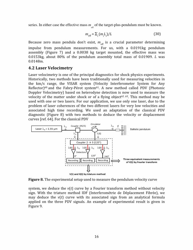
4.2LaserVelocimetryLaservelocimetryisoneoftheprincipaldiagnosticsforshockphysicsexperiments.Historically, twomethodshavebeen traditionallyused formeasuringvelocities inthe km/s range, the VISAR system (Velocity Interferometer System for AnyReflector)60and the Fabry-Pérot system61. A new method called PDV (PhotonicDopplerVelocimetry) basedonheterodynedetection is nowused tomeasure thevelocity of thematter under shock or of a flying object62,63. Thismethodmay beusedwithoneortwolasers.Forourapplication,weuseonlyonelaser,duetotheproblemof lasercoherencesof thetwodifferent lasers forvery lowvelocitiesandassociated high time recording. We used an adaptation of the classical PDVdiagnostic (Figure 8) with two methods to deduce the velocity or displacementcurves[ref.64].FortheclassicalPDV
Figure8.Theexperimentalsetupusedtomeasurethependulumvelocitycurvesystem,wededuce thev(t) curvebyaFourier transformmethodwithoutvelocitysign. With the triature method IDF (Interferométrie de Déplacement Fibrée), wemay deduce the v(t) curve with its associated sign from an analytical formulaapplied on the three PDV signals. An example of experimental result is given inFigure9.
(30)

17
Figure9.v(t) curvesdeduced fromPDV (red)and IDF (blue)on shot48onPOMtarget]4.3Laser
The“Elfie”laseratLULI,theLaboratoirepourl’UtilisationdesLasersIntensesatÉcolePolytechnique,uses theCPA techniqueandcanoperateat1057nm(1ω)aswell as 528nm (2ω) (Table III). At 1ω, energy ranges up to 12 J on targetwith arepetitionintervalof20min.Thecontrastratio(ratiobetweenpulseandprepulseintensity)isbetterthan107.At2ωand400fs,theELFIElaseroffers5Jpulseenergy.Italsooffersthepossibilitytomodulatethepulsedurationfrom400fsupto80psby changing parameters of the compressor. The experimental setup is shown inFigure10.
TableIII.ElfieLaserParameters
Wavelength 1057nmPulseduration 400fs 80psPulseenergy(J) 12 12
18
Figure10.LULI/Elfieexperimentallayout
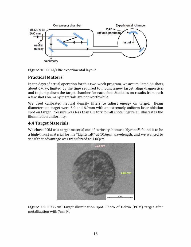
PracticalMattersIntendaysofactualoperationforthistwo-weekprogram,weaccumulated64shots,about6/day,limitedbythetimerequiredtomountanewtarget,aligndiagnostics,andtopumpdownthetargetchamberforeachshot.Statisticsonresultsfromsuchafewshotsonmanymaterialsarenotworthwhile.We used calibrated neutral density filters to adjust energy on target. Beamdiametersontargetwere3.0and6.9mmwithanextremelyuniformlaserablationspotontarget.Pressurewaslessthan0.1torrforallshots.Figure11illustratestheilluminationuniformity.
4.4TargetMaterialsWechosePOMasatargetmaterialoutofcuriosity,becauseMyrabo48foundittobeahigh-thrustmaterialforhis“Lightcraft”at10.6µmwavelength,andwewantedtoseeifthatadvantagewastransferredto1.06µm.
Figure 11.0.377cm2 target illumination spot. Photo of Delrin (POM) target aftermetallizationwith7nmPt

19
WechoseAlbecauseitisamajorspacecraftcomponentandthisworkisapplicabletopropellingobjects inspace.WandAuwerechosen forcomparisonwithref.25results. Ta was chosen to give a further idea of the variation of Cm with atomicweight.
5.0Results
5.1MomentumCouplingCoefficientFigures12-15showtheCmvaluesweobtainedvs.incidentfluenceΦ.ForPOMandAlinthisshort-pulseregime,thesearethefirstmeasurementsintheliteraturethatgivea reasonably clearvalue for the fluenceΦopt atwhichmaximumCmoccurs.Awordabouthowweidentified“optimum,”anditsuncertainty,fromourdata.Wherewehadenoughdatatoshowacleartrend,wechosethefluenceatwhichCmwasamaximum,oroneatwhichmorefluencecouldnotproduceabetterresultforCm.
Figure12.CmforPOMat80psand400fs,1057nm

20
Figure 13. Cm for aluminum at 100ps and 400fs, 1057 nm. Experimental datacomparedwithsimulationresults.Forthe80psdata,Φoptis30kJ/m2.For400fs,wechoseΦopt=50kJ/m2because,asapracticalmatter, nothingisgainedbygoingtohigherfluence.ThesolidlineshowsapreliminarymodelingusingtheCEAESTHERcodeat80ps.ThedashedlinesshowsimulationresultsfromDLRwithPolly-2Tfor100ps and 500fs pulse durations at 1064nm (see §5.1 for description of thesecodes).Ingeneral,ourerrorbarsforanindividualdatapointare±10%forbothfluenceandCm.TheuncertaintyinCmmayhavebeenduetodifferencesinsamplepreparation.TheuncertaintyofΦopt,particularlywherethedatashowsasteepriseorfallinCmoneithersideofΦoptisalsoshowninthetable.Thisuncertaintyhaslessmeaningin
21
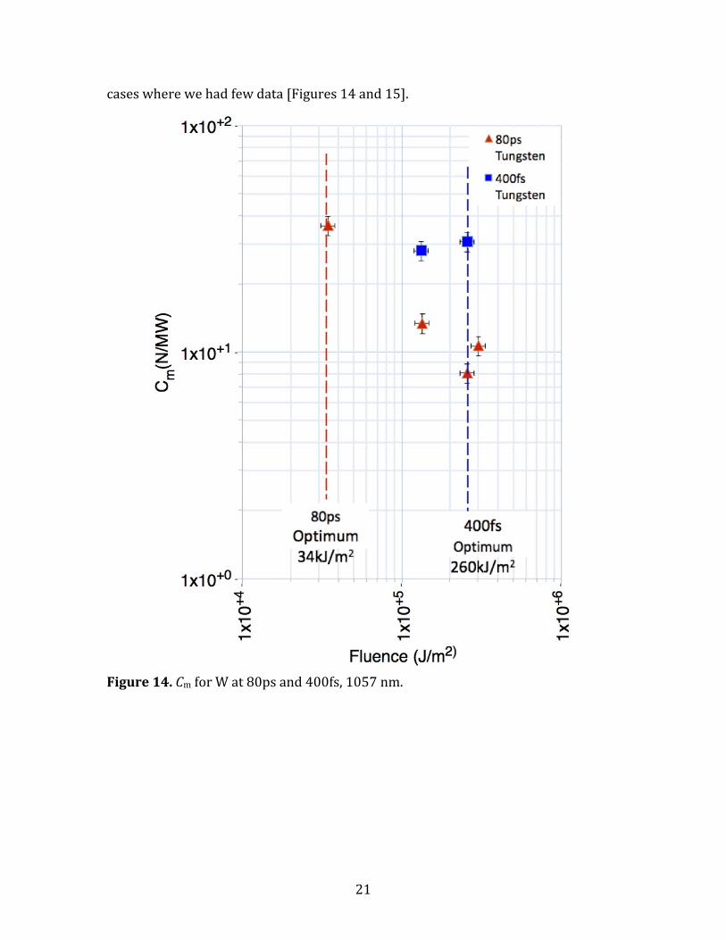
caseswherewehadfewdata[Figures14and15].
Figure14.CmforWat80psand400fs,1057nm.

22
Figure15.CmforAuandTaat80ps,1057nm

23
Ouraluminumtargetswere99.9%pure,fromGoodfellow,Inc.
Figure16.3DrepresentationofthealtitudeprofileonDelrin.Mostofthestructureweseearisesfrommachiningdefects.ESTHER64isaLagrangianmonodimensionalhydrodynamiccodewhichincludestheresolution of the Helmholtz equation which allows us to describe the laserpropagationandabsorptionintothematter.Weuseamulti-phaseequationofstatefor aluminum. Optical absorption is calculated by using Palik data65 when thematter is solid. In the plasma domain, absorption is given by classical inverseBremsstrahlung formula66. For aluminum, we also could use hydrodynamicsimulationswiththecodePolly-2T,describedinmoredetailinPovarnitsyn,etal67,tomodelthetwopulsedurations.Thiscodeisbasedonthetwo-temperaturemodelforlaser-materinteractionwithmetaltargets68,andusestheHelmholtzequation69forcouplinglaserenergyintothetarget.Semi-empiricalequationsofstatearetakenfor material description including a dynamic model for dielectric permittivity,electron-phononcouplingandheatconductivity forawiderangeof temperatures.Polly-2T was provided by Mikhail Povarnitsyn from the Joint Institute of HighTemperaturesattheRussianAcademyofSciences,Moscow.5.2AblatedMassMeasurementsTests with both confocal chromatic analysis (CCA, STIL sensor) and scanningelectron microscopy analysis (SEM, FEI XL30 ESEM LaB6) were inconclusiveregarding ablated mass. The samples were too rough and irregular to permitdeductionofablationdepthinthethelaserilluminatedregions.[Figures16-18]

24
Wenote thatEq. (28)givesapredictedablationdepthofatmost770µmforPOMand31µmrespectively forAl,usingηAB=0.5andthemaximumvaluesofCmandΦforthesematerialsfromTableI,sothisresultisnotsurprising.
Figure 17. SEM image of an aluminum samplewithmagnifications 10k(top) and3k(bottom)atΦ=10kJ/m2.Left-to-right:unilluminatedsample,middle,andcenterof illumination.Wesee characteristic structureof shortpulse illumination,butnoclearboundarythatpermitsestimationofdepth.Asregardsablationdepth,similarresultswereobtainedwithtungstenandtantalumsamples,andwithSEMofDelrinwhichwemetalizedwithplatinumaftertheshottomakeSEMpossible.
Figure18.(a)3Drepresentationofanaluminumsampleaftertheshot

25
Figure18 (b).Altitudeprofileofasample,usingCCA.Ourmeasurementsgaveaninconclusiveresultforablationdepth.
TableIVgivesourresultsforAlandPOM,withtheiruncertainties.6.0DiscussionOurbestestimatesofmeasurementuncertaintyareincorporatedintotheerrorbarsshown inFigures12-15.Errorbars forCmandΦoptdata forAlat400fsare±20%ratherthan±10%inotherdata.Thismaybepartlyduetoenergyuncertaintyearlyinthe10-dayexperimentserieswhenthe400fsdataweretaken.ModelingshowninFigure13indicatesslightlyhigherCmforAlat400fsthanat80ps.Datashowsasimilartrendalthoughscattermakesconclusionstenuous.BothdataandmodelingshowhigherΦoptdataforAlat400fsthanat80ps.WefindsimilarCmvaluesamongthemetals,andnotmuchdifferencefrompreviousworkintheultrashortrange,norfromtheDLRsimulation27.70forthelongerpulses.ForPOM,we foundagiganticCmbut there isnoobvious reasonwhy it shouldbelargeatboth1.06and10.6µmwavelengthsotherthanitslargemolecularmass.Astowhyitshouldgiveafactor-of-sixsmallerresultat400fsthanat80ps,ultrashort-pulseCmshoulddependprimarilyontensilestrength,lowerσygivinghigherCm.WedoseethateffectcomparingCmforPOMtothatforAlinthe400fsdata[TableV]. For aluminum, the measured coupling coefficient at 80ps is about three times
TableIV.OptimumcouplingresultsforAlandPOMat1057nm
Material Al POMPulsewidth Cm(N/MW) Φ(kJ/m2) Cm(N/MW) Φ(kJ/m2) 400fs 30±5 50±10 125±12 32±680ps 28±5 30±6 773±70 40±8

26
smallerthanthe100N/MWwehaveassumedat100psforsomeproposedsystemsbased on LASNEX simulations in ref. 26. This reference treated 530nm and 20ps,whileourapplicationswerefor355nmand80ps.Still,thisdiscrepancyissignificant.Theoptimumfluenceisfourtimeslargerthanweassumedpreviously.TheseresultsarenotaseverelimitationbecausehigherfluenceoffsetslowerCmtogive the same performance originally claimed for these systems,44,45albeit at thecostofhigherlaseraveragepower.
TABLEV:NewResultsComparedtoExistingShortPulseCmDataFluence(kJ/m2) Cmopt(N/MW) Pulsewidth Material Referenceno.
20 18 50fs Ti 23
5.2 42 130fs Mo 24
20 40 130fs W 2517 85 130fs Au 2510 25 130fs Li 2513 49 130fs Fe 25
13 25 130fs GAP 25
12 18 130fs Al 2530±20% 30±20% 400fs Al Thiswork32±10% 120±10% 400fs POM Thiswork260±10% 30±10% 400fs W Thiswork5.3±10% 37±10% 80ps Au Thiswork42±10% 29±10% 80ps Ta Thiswork40±10% 780±10% 80ps POM Thiswork30±20% 28±20% 80ps Al Thiswork36±10% 36±10% 80ps W Thiswork
On the good side, Eq. (4) shows thatwhenwe do deliver the larger 80ps fluencewith much lower Cm, we may expect an aluminum surface to have about twicelongerlifetimeperlaserpulseunderoptimumirradiationconditions.Ourmost pleasant surprisewas the performance of POM,which gave an80psCmvalue of 773N/MW, larger than any other reported unconfined, passive(nonenergetic)materialatshortpulsedurations.ThisCmistoolargeformostlaserlaunchprojects[seeFigure6],butitisusefulfromthefollowingpointofview:forlaserlaunchprojects,usingtheTableIIparameters,wepredictthatwecancastablationfuelfromamixtureof,e.g.,AldustandPOMtoobtain300N/MW,oranyothervaluewewantintherangefrom30to770at80ps.Therequiredfluence(~30kJ/m2)isaboutthesameforbothmaterials.Forreasons

27
havingtodowiththeabsenceofavailablelasersystemdesignsat400fscapableof100to1kJpulses,thispulsedurationispresentlynotattractivecomparedto80ps,so itdoesn’tconcernusthatCmopt forPOMat400fs ismuch less thanat80ps.WecanalsoeasilycreateafuelwithCm=100N/MW,asrequiredforthereference44and45spacesystemdesigns.WedoexpectlargerCmformetaltargetsatthesecondandthirdharmonics(530and352nm).
Figure19.Ourdatavs.plasmatheoryfromref.10anddatalistedthere(grey).Thehorizontalaxisparameterisexplainedin§3.Figure 19 show how our Cmopt data for aluminum compares with that of otherauthors at 80ps and 400fs. Clearly there is good agreement at 80ps, and lessagreementat400fsasexpectedfollowingthe§1.4discussion.At 400fs, it is reasonable forAu andFe to have higherCmbecause of their largeratomicweight.At80ps,AuandWhavelargerCmthanAlandTaforthesamereason.The limited number of data points for these materials did not permit strongconclusions.Aswepointedoutearlier,themajorinfluenceat50-400fsshouldbeadependenceon tensilestrength, rather thanatomicweight, lowerσygivinghigherCm.Thispredictionisapproximatelyborneout.POMperformsdramaticallyat80ps.

28
Figure20.Numerical simulationof thermal coupling vs. pulseduration and laserfluenceonaluminum,includingshockthermalization.Fullsymbolsdenoteablationwhereashollowsymbolsshowthermalcouplingbelowablationthreshold.7.0ConclusionsFor the first time, we have measured the single-pulse mechanical couplingcoefficienttoPOMandsomemetalsat1057nm,80psand400fs,andtheassociatedoptimumfluences.WefoundgiantCmresultsforPOMat80ps,1057nm.ForAl,therewas not much difference from previous work in the ultrashort range, nor fromScharring’s simulation for the longer pulses. We found a large difference fromFournier’s simulation for Al using LASNEX, onwhichwe based some of our pastlaser propulsion performance extrapolations. We can compensate these by usingmore laser fluence. We were not able to measure mass loss in this series. WeproposedusingacastmixtureofAldustandPOMinvaryingproportionstoobtainCm values between 30 to 770N/MW. We intend to buttress this proposal withmeasurementsinthenearfuture.
29
8.0WhatisStillUnknownTwomeasurements are still urgently needed: the ablation efficiency and thermalcoupling coefficients associated with our data. Figure 20 shows an analysis ofsimulationsinreference70withrespecttotheresidualheatremaininginthetargetafter ablation. The results shown for ultrashort pulses, typically known as “coldablation,” giveushope for theutility of 1-10pspulses. These shoulddemonstrateCth<6%at~30kJ/m2.However,at fluencesabove6kJ/m2,10-100pspulsesare thebest from this crucial viewpoint. Such fluences will be useful whenmaximum IspratherthanmaximumCmisthegoal(see§3.4).Thiseffectarisesbecausethelongerpulsesdonotaddsomuchthermalcouplingfromshock.9.0AcknowledgmentWe thank the ELFIE technical team for their support before and during theexperimentalcampaignandtheLULIProgramCommitteeforhavingallocatedpluri-annualbeamtimetoourproposal.Aside fromtheauthor list, thesepeople includeDiona Badarau, Joanna De Sousa, Edouard Veuillot, Pascal Guehennec and PierreUntereiner.WealsothankAlainBurrandSuzanneJacomet, fromCEMEF, for theirhelpin3DconfocalchromaticandSEMstudies.TheresearchexploringanewareainSpaceSciencewaspartlyfundedbytheCNESthroughgrantAVP-CT-0-1603.10.0References1F. Tsander, “Flight to other planets,” (1924) in Ye. Moshkin, Development of Russian Rocket Technology, Mashinostroyeniye Press, Moscow (1973) (in Russian)2K. Tsiolkovsky, "Plan of Space Exploration," (1926) (in Russian), available in English in “Exploration of the Universe with Reaction Machines: Exploring the Unknown,” NASA History Series. NASA SP 4407, Washington, D.C. (1995)3H. Oberth, "Die Rakete zu den Planetenräumen", (The Rocket to the Planet Spaces) Oldenbourg Verlag, München (1923)4E. Sänger, “Zur Theorie der Photonenraketen,” Probleme der Weltraumforschung (IV. Internationaler Astronautischer Kongress, Zürich 1953; S. 32, Biel-Bienne: Laubscher (1955) 5A.Kantrowitz,“PropulsiontoOrbitbyGround-BasedLasers,”AstronauticsandAeronautics,10,No.5,1972,pp.74–76.6C. R. Phipps, “Pulsed lasers for clearing debris in LEO and GEO,” paper LSSE1-1, Optics and Photonics International Conference, Yokohama, 17-20 May 2016 (2016)7Yu.Afanas’ev,N.Basov,O.Krokhin,N.MorachevskiiandG.Sklizkov,"Gas-dynamicprocessinirradiationofsolids",Soviet.Physics.-Technical.Physics.14,no.5,669-676(1969)

30
8A.Augustoni,P.Ermer,R.Heckler,G.Kuwashima,J.McKayandR.Rudder,"TheinteractionofhighenergysinglepulseXeFlaserradiationwithsolidtargets,"reportAFWL-TR-85-126,1986,U.S.AirForceResearchLaboratory,AFB,NM(notpaginated)9P.Combis,J.DavidandG.Nierat,"MesuredesEffetsMécaniquesdanslesExpériencesd'InteractionLaser-MatiereaEclairementModéré",RevueScientifiqueetTechniquedelaDefense,CEL-Valentonno.41992,pp.59-75,CentredesEtudesLimeil-Valenton,B.P.no.27,941956Villeneuve-Saint-GeorgesCedex,France10C.Phipps,T.Turner,R.Harrison,G.York,W.Osborne,G.Andersson,X.Corlis,L.Haynes,H.Steele,K.SpicochiandT.King,“ImpulseCouplingtoTargetsinVacuumbyKrF,HFandCO2Lasers”J.Appl.Phys.64,pp.1083-96(1988)11C.Duzy,J.Woodroffe,J.HsiaandA.Ballantyne,“InteractionofapulsedXeFlaserwithanaluminumsurface",Applied.Physics.Letters.Vol.37,no.6,1980,pp.542-54412J.McKayandP.Laufer,“SurveyofLaser-ProducedPressureandImpulseData,”PhysicalSciences,Inc.,FinalRept.PSI-1012/TR-757,NewEnglandBusinessCenter,AndoverMA,1987,pp.1–236.13D.GreggandS.Thomas,"Momentumtransferproducedbyfocusedlasergiantpulses",Journalof.AppiedPhysics.Vol.37no.7.,2787-2789(1966)14B.Xu,Q.Wang.X.Zhang,S.Zhao,Y.Xia,L.Mei,X.WangandG.Wang,““ImpulsetransfertothesurfaceofaluminumandcopperfromapulsedNd:YAGlaser,”Appl.Phys.B57277-80(1993)15D.Rosen,D.HastingsandG.Weyl,"Couplingofpulsed0.35-mmlaserradiationtotitaniumalloys",Journalof.Applied.Physics.Vol.53no.8pp.5882-5890(1982)16D.Rosen,P.Nebolsine,andP.Wu,"Laserimpulseapplicationsresearch",paperV1,Proceedingsofthe.AIAAConferenceontheDynamicsofHighPowerLasers,Cambridge,MA(1978)17R.Rudder,reportAFWL-TR-74-100,U.S.AirForceResearchLaboratory,KirtlandAirForceBase,NM,pp.189-198(1974)18V.Shui,L.YoungandJ.Reilly,"ImpulsetransferfrompulsedCO2laserirradiationatreducedambientpressures",AIAAJournalvol.16,649-50(1978)19I.Ursu,I.Apostol,D.Barbulescu,I.MihailescuandM.Moldovan,"Plasma-targetcouplinginthecaseofTEA-CO2laserproducedbreakdowninfrontofasolidtarget",OpticsCommunications..vol.39,180-185(1981)20T.PucikandR.Crawford,“OpticalLaserImpulseCouplingDataPackage”,RDAreport2.28.90.1990,Logicon/R&DAssociates,P.O.Box92500,LosAngeles,CA90009,notpaginated21B.D’Souza,“Developmentofimpulsemeasurementtechniquesfortheinvestigationoftransientforceduetolaser-inducedablation,”Ph.D.dissertation(2007)

31
22B.Wang,H.TsurutaandA.Sasoh,“Impulsegenerationbymultiple-pulselaserablationwithobliqueincidence,”paperLSSE2-4,Proc.LaserSolutionsforSpaceandtheEarthMay17-20,2016,Yokohama(2016)23E.Loktionov,Yu.S.ProtasovandYu.Yu.Protasov,“Thermophysicalandgas-dynamiccharacteristicsoflaser-inducedgas-plasmaflowsunderfemtosecondlaserablation,”QuantumElectronics,44,225-232(2014)24C.Phipps,J.Luke,D.Funk,D.Moore,J.GlowniaandT.Lippert,“Measurementsoflaserimpulsecouplingat130fs”,SPIE5448,pp.1201-1209(2004)25C.Phipps,J.Luke,D.Funk,D.Moore,J.GlowniaandT.Lippert,“LaserImpulseCouplingat130fs,”App.Surf.Sci..,2524838-4844(2006)26K.Fournier,“LASNEXcalculationsoflaser-couplingcoefficientsforAltargets,”UCRL-Pres-226849,p.29(2006)27S.Scharring,J.WilkenandH.-A.Eckel,“Laser-basedremovalofirregularlyshapedspacedebris,”OpticalEngineering,56,p.011007-4(2017).doi:10.1117/1.OE.56.1.01100728C. R. Phipps, M. Birkan, W. Bohn, H.-A. Eckel, H. Horisawa, T. Lippert, M. Michaelis, Y. Rezunkov, A. Sasoh, W. Schall, S. Scharring and J. Sinko, “Review: Laser Ablation Propulsion,” J. Propulsion and Power, 26 no. 4 pp. 609-637 (2010)29C.Phipps,unpublished30A.Ovsianikov,S.Passinger,R.HoubertzandB.Chichkov,LaserAblationandItsApplications,Springer,NewYork,2007,pp.121–156,Chap.631B. Esmiller, C. Jacquelard, H.-A. Eckel and E. Wnuk, “Space debris removal byground-basedlasers:mainconclusionsoftheEuropeanprojectCLEANSPACE,”Appl.Opt.53(31):I45–I54(2014),figureusedbyDr.Eckel’spermission32R.Soulard,M.Quinn,T.TajimaandG.Mourou,“ICAN:anovellaserarchitecturefor space debris removal,” ActaAstronaut. 105 (1) 192–200 (2014) 33T.Ebisuzaki,M.Quinn,S.Wada,L.Piotrowski,Y.Takizawa,M.Casolino,M.Bertaina,P.Gorodetzky,E.Parizot,T.Tajima,R.SoulardandG.Mourou,“DemonstrationdesignsfortheremediationofspacedebrisfromtheInternationalSpaceStation,”ActaAstronaut.,112,102-113(2015)34L.Daniault,M.Hanna,L.Lombard,Y.Zaouter,E.Mottay,D.Goular,P.Bourdon,F.DruonandP.Georges,“Coherentbeamcombiningoftwofemtosecondfiberchirped-pulseamplifiers,”Opt.Lett.36(5),621-623(2011)35F.diTeodoro,“PulsedFiberLasers,”chapter16,pp.463-498inHighPowerLaserHandbook,McGrawHill(2011)36J.Bourdorionnet,C.Bellanger,J.PrimotandA.Brignon,“Collectivecoherentphasecombiningof64fibers,”Opt.Express19(18)17053-17059(2011)37A.Klenke,S.Breitkopf,M.Kienel,T.Gottschall,T.Eidam,S.Hädrich,J.Rothhardt,J.Limpert and A. Tünnermann, “530W, 1.3mJ, four-channel coherently combinedfemtosecond laser chirped-pulse amplification system,” Opt. Lett. ,38 (13) 2283-2285(2013)

32
38C.Phipps,C.Bonnal,F.Masson,M.Boustie,L.Berthe,S.Baton,E.Brambrink,J.-M.Chevalier,L.Videau,S.BoyerandM.Schneider,“SmallpayloadtransfersfromearthtoLEOandLEOtointerplanetaryspaceusinglasers,”paper679,7thEuropeanConferenceforAeronauticsandSpaceSciences,Milan(2017)39 http://www.hilase.cz/en/advanced-dpssl-laser-dipole-100-delivers-1kw-performance/ 40http://www.eosenergystorage.com/technology-and-products/, page 2 41C.Phipps,G.Albrecht,H.Friedman,D.Gavel,E.George,J.Murray,C.Ho,W.Priedhorsky,M.MichaelisandJ.Reilly,“ORION:Clearingnear-Earthspacedebrisusinga20kW,530nm,Earth-based,repetitivelypulsedlaser,”LaserandParticleBeams14(1),1-44(1996)42C.Phipps,K.Baker,S.Libby,D.Liedahl,S.Olivier,L.Pleasance,A.Rubenchik,J.Trebes,E.George,B.Marcovici,J.ReillyandM.Valley,“Removingorbitaldebriswithlasers,”Adv.SpaceResch.49,1283-1300(2012)43C.Phipps,J.ReillyandJ.Campbell,“Optimumparametersforlaser-launchingobjectsintolowEarthorbit,”LaserandParticleBeams,18(4)661-695(2000)44C.R.Phipps,“L’ADROIT–Aspaceborneultraviolet lasersystemforspacedebrisclearing,”ActaAstron.104,243-255(2014)45C.R.PhippsandC.Bonnal,“Aspaceborne,pulsedUVlasersystemforre-enteringor nudging LEO debris, and re-orbiting GEO debris,” Acta Astron. 118, 224-236(2016)46C.Phipps,C.Bonnal,F.Masson,M.Boustie,L.Berthe,S.Baton,E.Brambrink,J.-M.Chevalier,L.VideauandS.Boyer,“TransfersfromearthtoLEOandLEOtointerplanetaryspaceusinglasers,”ActaAstron.(submitted)47J.Ihlemann,F.Beinhorn,H.Schmidt,K.Luther,J.Troe,“PlasmaandplumeeffectsonUVlaserablationofpolymers,”SPIE5448(2004)572–580.48L. N. Myrabo, D. G. Messitt and F. B. Mead Jr., “Ground and flight tests of a laser propelled vehicle,” paper AIAA 98-1001, 36th AIAA Aerospace Science Meeting & Exhibit, 12-15 January 1998, Reno, NV (1998)49C.PhippsandJ.Luke,“Laserspacepropulsion–applicationsat twoextremesoflaserpower,”inLaserAblationanditsApplications,C.Phipps,ed.,SpringerSeriesinOpticalSciences,129,Springer,NewYork(2007),pp.407-43450J.SinkoandC.Phipps,“ModelingCO2laserablationimpulseofpolymersinvaporandplasmaregimes,”Appl.Phys.Lett.,95,131105-1to131105-3(2009)51A.P.Papavlu,L.Urech,T.Lippert,C.Phipps,J.HermannandA.Wokaun,“fsLaser-inducedPlasmasfromEnergeticPolymers:TowardsMicro-LaserPlasmaThrusterApplication,”PlasmaProcess.Polym.13611-622(2016)52C. Phipps, “AnAlternateTreatment of theVapor-PlasmaTransition,” Int.J.Aero.Innovations3,45-50(2011)53TheSESAMEequation-of-statedatabaseismaintainedbygroupT-1atLosAlamosNationalLaboratory([email protected]);seeS.P.LyonandJ.D.Johnson,"SESAME:TheLosAlamosNationalLaboratoryEquationofStateDatabase,"LANLReportNo.LA-UR-92-3407,1992foradditionalinformation.

33
54C.Phipps,R.Harrison,T.Shimada,G.York,T.Turner,X.Corlis,H.Steele,L.HaynesandT.King,"EnhancedVacuumLaser-impulseCouplingbyVolumeAbsorptionatInfraredWavelengths",LaserandParticleBeams,8,281(1990)55C.PhippsandR.Dreyfus,"Laserablationandplasmaformation"inLaserIonizationMassAnalysis,AkosVertes,RenaatGijbelsandFredAdams,eds.,ChemicalPhysicsMonographs124,pp.369-441(1993)56C. Phipps and J. Luke, paper IEPC 319, International Electric PropulsionConference,PrincetonOctober30,2015[Figure5]57B. Poling, J. Prausnitz and J. O’Connell, TheProperties ofGasesandLiquids, 5thedition,McGraw-Hill,NewYork,2001,7.9-7.1158J.SinkoandC.Phipps,“ModelingCO2laserablationimpulseofpolymersinvaporandplasmaregimes,”Appl.Phys.Lett.95,131105,200959C. Phipps, J. Reilly and J. Campbell, “Optimum parameters for laser-launchingobjectsintolowEarthorbit,”LaserandParticleBeams,18(4),661-695(2000)60L. Barker and R. Hollenbach, “Interferometer technique for measuring thedynamicmechanicalpropertiesofmaterials,”ReviewofScientific Instruments,36(11),p.1617-1620.(1965)61M. Durand and P. Laharrague, “System of velocitymeasurement of a projectileusing a Fabry-Pérot interferometer,” Proc. Ninth International Congress on H.SPhotographicSocietyofMotionPictureandTelevisionEngineers(1970)62O.T.Strand, D. R. Goosman, C. Martinez, T. L. Whitworth and W. W. Kuhlow,“Compactsystemforhigh-speedvelocimetryusingheterodynetechniques”,ReviewofScientificInstruments,77(8)083108(2006)63P.Mercier, J.Benier, A Azzolina, J-M.Lagrange and D.Partouche, “PhotonicDoppler velocimetry in shock physics experiments,” JournalDePhysique IV, 134,805-812(2006)64S.Bardy,B.Aubert,L.Berthe,P.Combis,D.Hébert,E.Lescoute,J.-L.RullierandL.Videau, "Numerical study of laser ablation on aluminum for shock-waveapplications: development of a suitable model by comparison with recentexperiments,”Opt. Eng. 56 (1), 011014 (2017) 65E.Palik,“HandbookofOpticalConstantsofSolids,”E.D.Palik,ed.Academic,NewYork(1985)66S.AtzeniandJ.Meyer-Ter-Vehn,“ThePhysicsofInertialFusion,”S.AtzeniandJ.Meyer-Ter-Vehn,eds.,OxfordUniversityPress(2004)67M. Povarnitsyn, N. Andreev, P. Levashov, K. Khishchenko and O. Rosmej,“Dynamics of thinmetal foils irradiated bymoderate-contrast high intensity laserbeams,”Phys.Plasmas19,0231101-8;doi:10.1063/1.368368768S. Anisimov, G. Kapeliovich and T. Perel’man, “Electron emission from metalsurfacesexposedtoultrashortlaserpulses,”Sov.Phys.JETP39,375-377(1974)69M.Povarnitsyn,N.Andreev,E.Apfelbaum,T.Itina,K.Khishchenko,O.Kostenko,P.Levashov and M. Veysman, “A wide range model for simulation of pump-probeexperiments with metals,” Appl. Surf. Sci258, 9480-9483 (2012); doi: 10.1016/j.apsusc.2011.07.017

34
70S. Scharring, R.-A. Lorbeer and H.-A. Eckel, “Numerical Simulations on Laser-Ablative Micropropulsiomn with Short and Ultrashort Laser Pulses,” Trans. JSASSAerospaceTech.14(ists30),Pb_69-Pb_75(2016).Doi:10.2322/tastj.14.Pb_69