Embed Size (px)
Citation preview

Laser illumination for orbital object characterisation
Nazim Ali Bharmal,[email protected]
Centre for Advanced Instrumentation, Durham University
GNOSIS29th July 2021
Workshop on Novel/Non-traditional
Observation Techniques

Background
Working in AO for twenty years, more
recently in laser propagation
I work in the Centre for Advanced
Instrumentation, Durham Uni
We (& I) design, fabricate (including metal
optics), and deliver + operate optical
instrumentation for astronomy
Often prototypes but also facility projects
Some space work e.g. JWST IFU mirrors and
OGSE for ESA EO
2
Debris mitigation
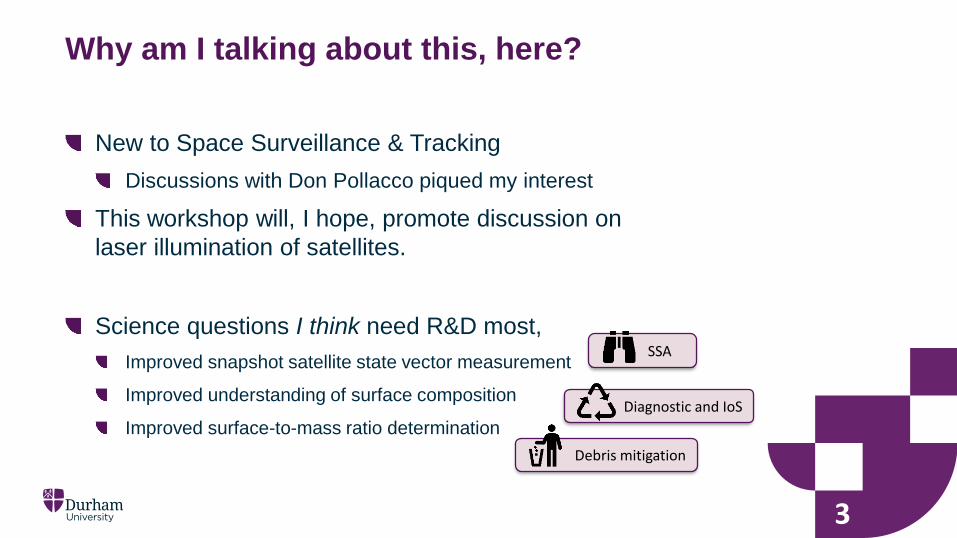
Why am I talking about this, here?
New to Space Surveillance & Tracking
Discussions with Don Pollacco piqued my interest
This workshop will, I hope, promote discussion on
laser illumination of satellites.
Science questions I think need R&D most,
Improved snapshot satellite state vector measurement
Improved understanding of surface composition
Improved surface-to-mass ratio determination
3
Diagnostic and IoS
SSA

Fundamental issues
4
Lasers have incredible brightness temperature
Sun has incredible irradiance
Put together, narrow-field and targeted is where
laser illumination will aid SST
c.f. Laser Ranging
Illuminating from ground
Possibility of space-based is another discussion
Therefore, seeing (atmospheric corruption) is
where to starthttps://xkcd.com/1522/

Quick overview
5
Laser/debris ranging takes advantage of LAGEOS et al
LIDAR—measures radial component of state vector
Infer angular components (in/cross-track)
To measure angular components,
Need to know where laser is pointing
Need a scale
To estimate composition,
Need to know illumination on target
How target responds to illumination: BDRF
To aid surface-to-mass ratio determination
Probably the above
Start with: where is the laser and
what is its illumination?
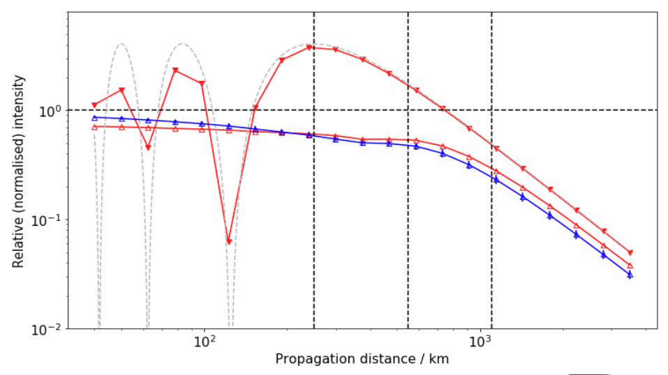
1m telescope, 1064nm laser, 1’’ seeing,
1.7J pulses ca.200W
beam waist, w, is 5cm
Fresnel number is 250km, Rayleigh distance 7.4km
Main effect is linear offset: tip/tilt in our parlance
6

Illumination
7
Can be confident we know what the illumination
profile is
Need to measure where the beam is going: fortunately this is
well explored in astronomy
Tomographic tip/tilt estimation (poster at AMOS) has 𝑃 > 0.25for 𝜎𝛼 ≤ 0.15′′ which is 0.42m i.e. less than the imparted tip/tilt
which has a 1-sigma of 0.82m.
Requires on 1m telescope a wide-field imager with ca.480 × 480pixels at ca.500Hz and low read-noise: feasible.
Conclude that, with active correction, can be confident
of precisely targeting 1m-size objects
Illumination
8
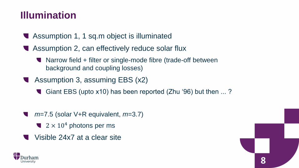
Assumption 1, 1 sq.m object is illuminated
Assumption 2, can effectively reduce solar flux
Narrow field + filter or single-mode fibre (trade-off between
background and coupling losses)
Assumption 3, assuming EBS (x2)
Giant EBS (upto x10) has been reported (Zhu ‘96) but then ... ?
m=7.5 (solar V+R equivalent, m=3.7)
2 × 10⁴ photons per ms
Visible 24x7 at a clear site

Illumination
9
If limit is 100 photons per exposure, how small
can we go?
Note that field is about 4m x 4m or 1.5’’ x 1.5’’ ... pretty tiny! but
deep, about 1200km.
Know that reflectivity is high at 1064nm so assuming
albedo=0.175 conservatively
About 10cm is answer at 550km distance
About 1m at 1500km distance
For small debris, need a more powerful laser or bigger
receiver: with 5m aperture, 1cm at 550km
Needn’t be diffraction limited...know where the target is

10
Recap
10
Have we answered sufficient questions to achieve
our goals?
To measure angular components,
Need to know where laser is pointing
Need a scale
To estimate composition,
Need to know illumination on target
How target responds to illumination: BDRF
To aid surface-to-mass ratio determination
Probably the above
Making a scale
11
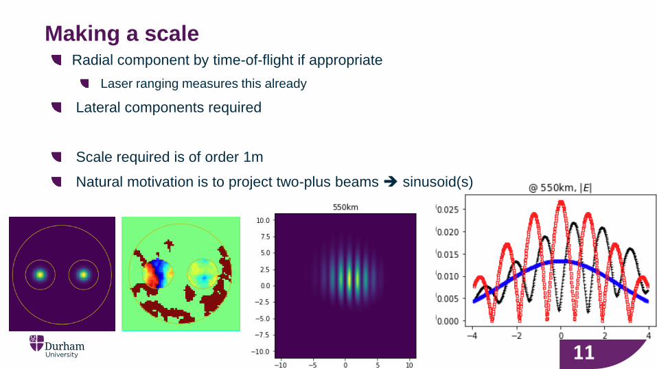
Radial component by time-of-flight if appropriate
Laser ranging measures this already
Lateral components required
Scale required is of order 1m
Natural motivation is to project two-plus beams sinusoid(s)

Making a scale
12
Can make a lateral scale but phase shift between
beams will cause scale phase and visibility to vary
A solution is high-speed scanning of fringes over target
Freeze fringes measure move fringes and repeat
Target motion within isoplanatic patch, ca 1’’, for 4ms
Aim to keep laser power at same levels
Could increase laser power but other issues: so far well below
solar power densities
Thus, equivalent to m=10 for 1 ms exposure
With CW can use AOM or similar to modulate frequency of
one beam fringe phase rotates and temporal signal
returns 1D velocity
Where would you do this?
13
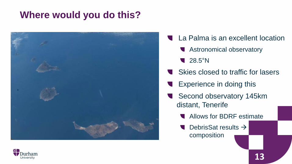
La Palma is an excellent location
Astronomical observatory
28.5°N
Skies closed to traffic for lasers
Experience in doing this
Second observatory 145km
distant, Tenerife
Allows for BDRF estimate
DebrisSat results
composition
Laser illumination from the ground for SST has some
promising applications
Advantages include day-night operation and ability to control
illumination on target
Technologies all exist and are CotS
Ability to control propagation is key to accurate illumination
Limited to night conditions for now
Ability to project pattern is key to precision location determination
Outstanding: determine precision of projected fringes state vector
estimation
Summary


![Illumination-Aware Age Progressionnovel illumination-aware age progression technique, lever-aging illumination modeling results [1,31], that properly account for scene illumination](https://img.dokumen.tips/doc/110x75/5e72745a0ac7de5cbf4199be/illumination-aware-age-progression-novel-illumination-aware-age-progression-technique.jpg)