Embed Size (px)
Citation preview

USPAS09 at UNM Accelerator and Beam Diagnos9cs
Laser Diagnos9cs for H‐ Beams
Tom Shea (ORNL)USPAS and University of New Mexico Albuquerque NM, June 23‐26, 2009
1
Material adapted from presenta9ons by many people in the accelerator community, par9cularly: R. Connolly and Y. Liu.

USPAS09 at UNM Accelerator and Beam Diagnos9cs
Conven9onal Carbon Wire Scanner
• Requires special low power opera9on mode
• Abla9on from the wire may contaminate the superconduc9ng cavity
• Maintenance requires vacuum access
• Very radia9on hard • Excellent signal to noise ra9o
Advantages
Disadvantages
2

USPAS09 at UNM Accelerator and Beam Diagnos9cs
Carbon Wire Hea9ng
Calculations: Mike Plum (LANL, now @ORNL); also C. J. Liaw (BNL)
Temperature vs. time of 32 micron C wire380 MeV, 1.2 mm x 1.2 mm rms H- beam1 Hz, 100 microsecondFar more energy deposition at low H- beam energy
0
500 deg C
0 2 8 s64
• Low power beam mode required for intercep9ng devices:
– Short Macropulse: 50 microseconds (full power opera9ons: 1 ms) )
– Low rep rate: < 6 Hz (full power opera9ons: 60 Hz)
– Full power will destroy wire; measurement interrupts normal opera3ons
3

USPAS09 at UNM Accelerator and Beam Diagnos9cs
Laser Wire
Faraday Cup
Replace carbon wire with a laser beam
H‐
H0
electron
Bending Magnet
X‐scan
Y‐scan
x
y zH‐ b
eam
4

USPAS09 at UNM Accelerator and Beam Diagnos9cs 5
Lasers and H‐ BeamsFirst ioniza9on poten9al for H‐ ions is 0.75eV.
Photons with λ<1500nm can separate H‐ ion into free electron and neutral H.
The H‐ ion has no excited states so the electron is removed into the con9nuum.
Laser can be used to mark a por3on of beam by neutraliza3on.
Once a por9on of the beam is marked, measurements can be made on the neutral beam, the removed electrons, or the reduced beam current with beam current transformer or BPM stripline.
This method has been used at Los Alamos for transverse and longitudinal emibance measurements.

USPAS09 at UNM Accelerator and Beam Diagnos9cs 6
In 1938 R. Wildt proposed that photodetachmentof H‐ ions produced most of the con9nuous absorp9on in late‐type stars.
"It is now generally recognized that the nega9ve hydrogenion provides the principal source of opacity in stellaratmospheres." Chandrasekhar and Krogdahl, 1943
History of H‐ photodetachment

USPAS09 at UNM Accelerator and Beam Diagnos9cs
Toward a Laser Wire for SNS
Calculated cross section for H- photoneutralization as a function of photon wavelength.*
Nd:YAG laser has λ=1064nm where the cross section is about 90% of the maximum (at low beam energy).
*J.T. Broad and W.P. Reinhardt, Phys. Rev. A14 (6) (1976) 2159.
Horizontal Motor
Switch Motor
Vertical Motor
beam
Beam Pipe with view ports
Lens Motor
Lens Motor
• Scan laser transversely across ion beam
• Plot one of the following vs. laser beam posi9on:– Missing current in H‐ beam– Collected electrons liberated
from H‐ beam
7

USPAS09 at UNM Accelerator and Beam Diagnos9cs
Laser Monitor Development at BNL:Meassure laser-induced "notch" in beam current signal
Scope was set on infinite persistence for several hundredbeam pulses. This is difference signal at 200 MHz from upstream and downstream BPMs.
Laser Wire Profile with 100uA 200MeV Polarized Beam
Small Q-switched Nd:YAGlaser for similar 2.5 MeV test at LBNL
“You’ve gotta be a believer” – Roger Connolly (BNL)
8

USPAS09 at UNM Accelerator and Beam Diagnos9cs
Front End at ORNL – Jan 2003Laser Profile Monitor Results at 2.5 MeV
Horizontal Profile1/25/2003 13:06Gaussian fit plotted out to 2.5x SigmaSigma = 1.07 mm
Signal from electron collectorTop: laser intercepting beam core Bottom: laser intercepting beam tail
• Verifica9on of electron collection technique• Reliable measurements to about 3 sigma
“Now I’m a believer” – N. Holtkamp (ORNL)
9

USPAS09 at UNM Accelerator and Beam Diagnos9cs
SCL
1 2 3 4 5 321712 13 14 15
240 m 216 m 16 m140 m
LR Laser room
Laser wire station
Cryomodule number
Camera
Mirror
Power meter32
LR
Ring
Layout of the SNS Laser Wire System
CCLDTL
Target
MEBT
• 4 LW from 200 MeV
• 4 LW from 450 MeV
• 1 LW at 1 GeV
10
USPAS09 at UNM Accelerator and Beam Diagnos9cs
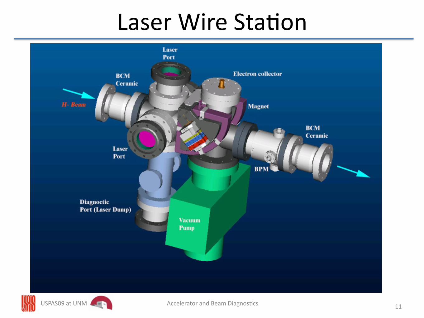
Laser Wire Sta9on
11

USPAS09 at UNM Accelerator and Beam Diagnos9cs
Laser Installa9on in Tunnel
12

USPAS09 at UNM Accelerator and Beam Diagnos9cs
Laser Requirements
Q‐switched Nd:YAG laser λ = 1.06 µm
frep = 30 Hz, Tw = 7 nsEp = 50 – 200 mJ
Injec9on seeded
Timing synchronized to SCL
Laser Room
• High pulse energy
• Small spot size
• Single wavelength
• Poin9ng stability
• Temporal stability
• Outside of radia9on area• Enclosed laser room with interlocked door
13
USPAS09 at UNM Accelerator and Beam Diagnos9cs
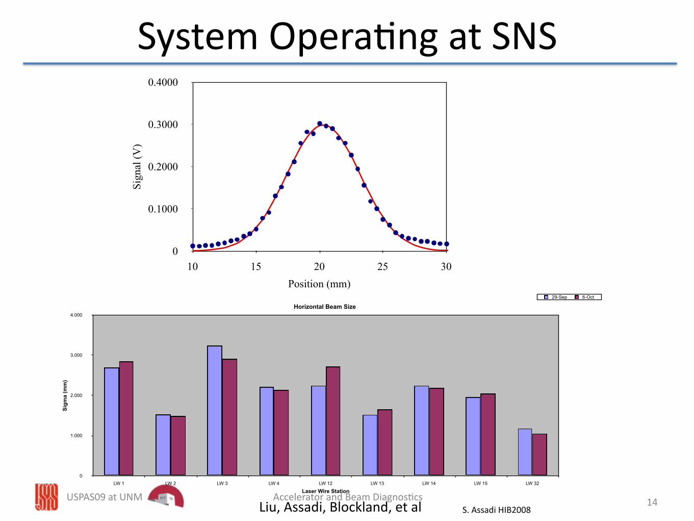
System Opera9ng at SNS
S. Assadi HIB2008
0
1.000
2.000
3.000
4.000
LW 1 LW 2 LW 3 LW 4 LW 12 LW 13 LW 14 LW 15 LW 32
Horizontal Beam Size
Sigm
a (m
m)
Laser Wire Station
29-Sep 6-Oct
0
0.1000
0.2000
0.3000
0.4000
10 15 20 25 30
Sign
al (V
)
Position (mm)
Liu, Assadi, Blockland, et al 14

USPAS09 at UNM Accelerator and Beam Diagnos9csPresentation_name
Laser: 20 mJ, 0.2 mm
Scin9llator
Laser‐based Emibance Monitor
Ho
H‐
D. Jeon, J. Pogge, Y. Liu, A. Menshov, I. Nesterenko, W. Grice, A. Aleksandrov, S. Assadi
• Technique proposed by R. Shafer as part of beam‐in‐gap system• System under construc9on is located upstream; HEBT Bending dipole deflects H‐ beam and
remaining electrons while Ho beam will travel free from the influence of dipoles, quads etc• Gas stripping background measured, appears low enough
15

USPAS09 at UNM Accelerator and Beam Diagnos9cs
Expected beam distribu9on at laser and 17.7 m downstream at scin9llator
Presentation_name
X Y
X’ Y’[rad]
[cm]
[rad]
[cm]
X Y
X’ Y’[rad]
[cm]
[rad]
[cm]
D. Jeon 16

USPAS09 at UNM Accelerator and Beam Diagnos9cs
Longitudinal Measurement at 2.5 MeV• Mode‐locked Ti‐Sapphire laser• Tune laser to ~ps pulses, H‐ bunch: ~100ps• Lock laser to sub‐harmonic of RF, scan rela9ve phase (9ming).
Complete system simulation – beam/laser interaction, electron transport – Victor Alexandrov
Electron Deflector
Electrontrajectory
17

USPAS09 at UNM Accelerator and Beam Diagnos9cs
Longitudinal Measurements2.5 MeV H‐, 402.5 MHz bunching freq, mode locked Ti‐Sapphire laser phase‐locked @ 1/5th bunching frequency
collected electron signal plobed vs. phase Measured and predicted bunch lengthvs. cavity phase seung
Grice, Assadi, et al 18
USPAS09 at UNM Accelerator and Beam Diagnos9cs
Summary
• Laser diagnos9cs have been a useful development for the par9cular case of high power H‐ beams
• Plenty of headroom for performance improvement and new applica9ons
19

USPAS09 at UNM Accelerator and Beam Diagnos9cs
Addi9onal Material
20

USPAS09 at UNM Accelerator and Beam Diagnos9cs 21
Lab frame laser wavelengthWavelength in 1GeVbeam frame.
Laser neutraliza9on cross sec9on• Calculated cross sec9on for H‐
photoneutraliza9on as a func9on of photon wavelength.*
• Nd:YAG laser has λ=1064nm where the cross sec9on is about 90% of the maximum.
• If laser beam crosses ion beam at angle θL, in lab the center of mass energy is given by:
ECM=γEL[1‐βcos(θL)]
• So Nd:YAG cross sec9on at 1GeV is about 70% of low‐energy cross sec9on
• *J.T. Broad and W.P. Reinhardt, Phys. Rev. A14 (6) (1976) 2159.

22
Since we are measuring a notch in the beam current we are interested in the fraction of the beam neutralized by the laser which is given by,
fneut = 1 - e-σ(E)Ft
Here σ(E), the cross section, is held constant, F is the photon flux (#/cm2s) and t is the travel time of the ions across the photon beam.
For instance the MEBT laser put out 50mJ/20ns/3mm2=4.5 x 1026 photons/cm2s.
The beam at 2.5MeV had velocity of β=0.073 giving fneut=90%
Higher photon flux is required as the beam energy increases for same signal. At200MeV we used 200mJ laser to get 72% neutralization.
Fraction of beam neutralized 1.0
0.8
0.6
0.4
0.2
0.0
Neut
raliz
atio
n fr
actio
n
10080604020Beam energy (MeV)

23
1.0
0.8
0.6
0.4
0.2
0.0Ne
utra
lizat
ion
frac
tion
120010008006004002000
Beam energy (MeV)
At increasing beam energies theLorentz boost in photon energyresults in decreasing cross sectionsabove about 500 MeV.
However the photon flux is alsoLorentz boosted by the same factoras the photon energy,
FCM=γFL[1-βcos(θL)]
The relativistic boost in the photon flux and the relativistic decrease in cross sectionapproximately cancel resulting in a nearly constant neutralization fraction from 200MeV to 1.2GeV.
Neutralization fraction of 50mJ, to 1.2 GeV
SNS Superconducting Linac Laser Wire System RAD OPS Training, February 23, 2009
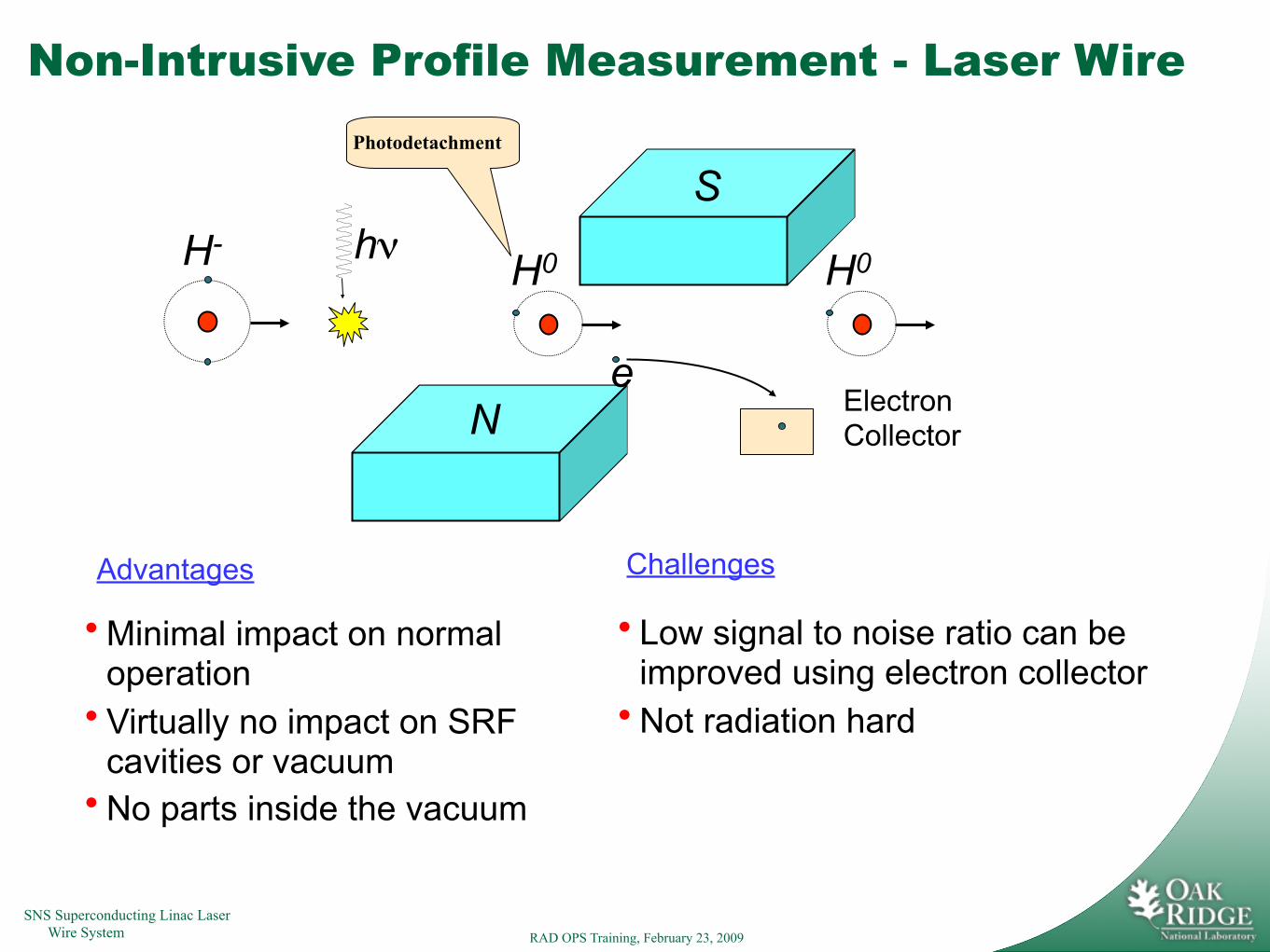
Non-Intrusive Profile Measurement - Laser Wire
hνH-
N
S
Electron Collector
H0
e
H0
Photodetachment
• Minimal impact on normal operation
• Virtually no impact on SRF cavities or vacuum
• No parts inside the vacuum
Advantages
• Low signal to noise ratio can be improved using electron collector
• Not radiation hard
Challenges
SNS Superconducting Linac Laser Wire System RAD OPS Training, February 23, 2009
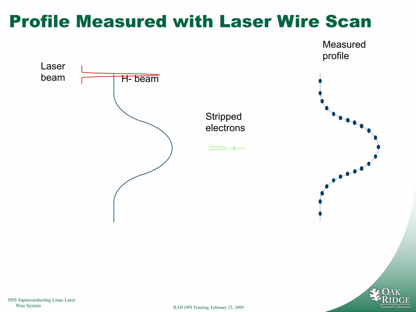
Profile Measured with Laser Wire Scan
H- beamLaser beam
Stripped electrons
Measured profile

SNS Superconducting Linac Laser Wire System RAD OPS Training, February 23, 2009
Schematic of Laser Wire Station Optics
Mirror
Lens
PhotodiodeBeam Dump
Flip-Mirror
From LTL
V-scan
H-scan
Ion Beam

SNS Superconducting Linac Laser Wire System RAD OPS Training, February 23, 2009
Laser Transport Line DiagnosticsEnd of SCLLaser room
Image of Cam 17 Image of Cam 5
SNS Superconducting Linac Laser Wire System RAD OPS Training, February 23, 2009
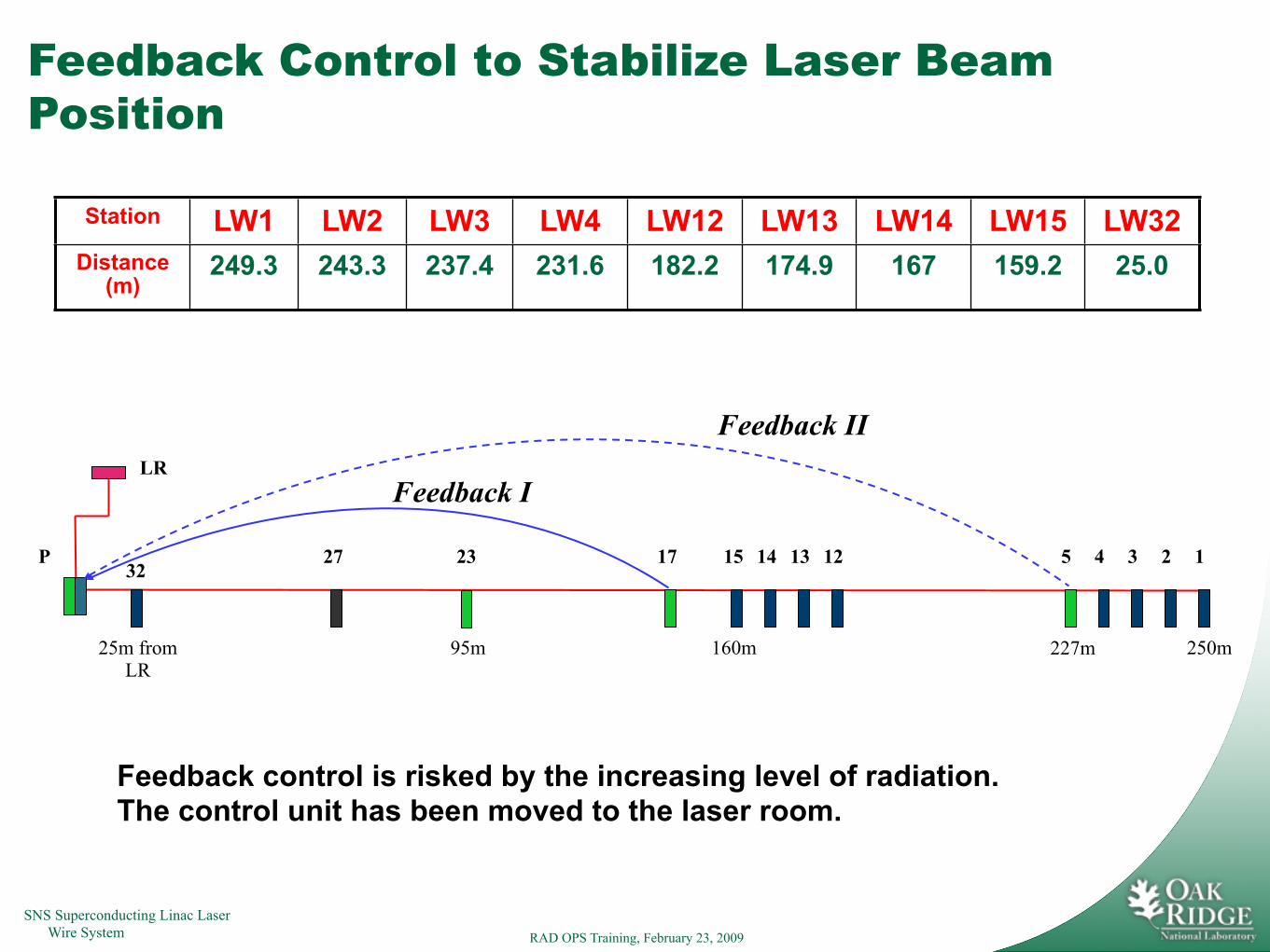
Feedback Control to Stabilize Laser Beam Position
Feedback control is risked by the increasing level of radiation.The control unit has been moved to the laser room.
1234532
P 27 23 17 12131415
LR
25m from LR
95m 160m 250m
Feedback I
227m
Feedback II
Station LW1 LW2 LW3 LW4 LW12 LW13 LW14 LW15 LW32Distance
(m)249.3 243.3 237.4 231.6 182.2 174.9 167 159.2 25.0

SNS Superconducting Linac Laser Wire System RAD OPS Training, February 23, 2009
Feedback on Feedback offFeedback on
Feedback Program to Control Laser Beam Drift