Embed Size (px)
Citation preview

Las Vegas Valley Construction Site Best Management Practices
Guidance ManualJANUARY 2009
Prepared by:Las Vegas Valley Stormwater Quality Management Committee and Clark County Regional Flood Control District

THIS PAGE LEFT BLANK INTENTIONALLY

Las Vegas Valley Construction Site Best Management Practices
Guidance ManualJANUARY 2009
Prepared by:Las Vegas Valley Stormwater Quality Management Committee and Clark County Regional Flood Control District

THIS PAGE LEFT BLANK INTENTIONALLY

Guiding Principles
Las Vegas Valley Construction Site BMP Guidance Manual January 2009
The Las Vegas Valley Construction Site Best Management Practices Guidance Manual (BMP Guidance Manual) was developed by the Las Vegas Valley Stormwater Quality Management Committee and Stormwater Stakeholders Working Group based on the following mission statement and guiding principles.
Mission Statement
Our goal is to comply with the Municipal Separate Storm Sewer System (MS4) Permit by developing construction and post-construction program enhancements that are:
• clear, simple and effective • consistent • cost–effective • consensus–based • fiscally and environmentally responsible • sensible for the Las Vegas Valley
Guiding Principles
1. Owners/operators of construction sites are ultimately responsible for compliance
with all applicable rules and regulations related to construction activity. 2. Owners/operators of construction sites should use their own experience and
professional judgment in selecting specific best management practices for each individual application.
3. Guidance on design and maintenance of best management practices provided in this
BMP Guidance Manual represents best practices in the industry, and establishes minimum standards of performance.
4. Owners/operators of construction sites may propose use of best management
practices not included in this BMP Guidance Manual, provided sufficient documentation is submitted to the local entity to demonstrate their effectiveness in the Las Vegas Valley environment.
5. The Las Vegas Valley Stormwater Quality Management Committee will regularly
update this BMP Guidance Manual to incorporate emerging practices and technologies. 6. The Cities of Las Vegas (CLV), North Las Vegas (CNLV), Henderson (COH), and
Clark County (County) have all adopted a policy of working with contractors and site owners/operators to achieve compliance with the program and an effective site runoff management plan.

THIS PAGE LEFT BLANK INTENTIONALLY
Acknowledgments
Las Vegas Valley Construction Site BMP Guidance Manual January 2009
The Las Vegas Valley Construction Site Best Management Practices Guidance Manual (BMP Guidance Manual) was prepared by MWH Americas, Inc., under a contract with the Clark County Regional Flood Control District on behalf of the Las Vegas Valley Stormwater Quality Management Committee. The Stormwater Quality Management Committee consists of representatives of each of the Co-Permittees under the municipal separate storm sewer system NPDES permit for Las Vegas Valley. These Co-Permittees are Clark County Regional Flood Control District, Clark County, the Cities of Las Vegas, North Las Vegas and Henderson. This BMP Guidance Manual was developed to assist the Co-Permittees and members of the public involved in planning, designing and implementing construction activities with the requirements set forth in the Nevada Stormwater General Permit for Construction Activity NVR100000 (the construction activity permit) and the ordinances of the Las Vegas Valley municipal entities. The Nevada Division of Environmental Protection (NDEP) issued and enforces the general construction permit. Staff members currently responsible for developing and implementing the permit are Clifford Lawson and Steve McGoff of the NDEP Bureau of Water Pollution Control. Other City and County staff and stakeholders who were involved in the development of this BMP Guidance Manual include the following: Kevin Eubanks, Clark County Regional
Flood Control District Dan Fischer, City of Las Vegas Jennifer Doody, City of North Las Vegas Al Jankowiak, City of Henderson Mark Silverstein, Department of Air
Quality and Environmental Management
Peggy Roefer, Southern Nevada Water Authority
Ed Thurnbeck, Jacobs Carter Burgess Mark Failla, Engineering and Vendors Mark Jones, Southern Nevada Home
Builders Association Joe Pantuso, Associated General
Contractors Pam Scott, Homeowners Associations Stuart Hitchen, Trade Associations Terry Murphy, Strategic Solutions
Special thanks to the Truckee Meadows Regional Stormwater Quality Management Program and Maricopa County for providing much of the information incorporated into this BMP Guidance Manual. The following staff members at MWH Americas, Inc., were responsible for preparing this BMP Guidance Manual: Edwin “Chip” Paulson, Project Manager Jason Jager Angela MacKinnon Alicia Duran Kazu Martinez

THIS PAGE LEFT BLANK INTENTIONALLY

Table of Contents
Las Vegas Valley Construction Site BMP Guidance Manual Page i January 2009
SECTION 1.0 – INTRODUCTION 1.1 Historical Background ................................................................................................... 1-1 1.2 Purpose of Manual ......................................................................................................... 1-1 1.3 Program Area .................................................................................................................. 1-2 1.4 Overview of Manual Organization .............................................................................. 1-2 1.5 Updates and Revisions to the BMP Guidance Manual ............................................ 1-3 1.6 Disclaimer ........................................................................................................................ 1-3 1.7 Comments ........................................................................................................................ 1-4 1.8 Distribution ..................................................................................................................... 1-4
SECTION 2.0 – STORMWATER QUALITY MANAGEMENT 2.1 Principles of Erosion and Sediment Control ............................................................. 2-1 2.2 Environmental Impacts of Runoff From Construction Sites ................................. 2-3 2.3 Best Management Practices .......................................................................................... 2-4 2.4 NPDES Permit Regulations ......................................................................................... 2-4 2.5 Nevada’s General Permit for Construction Activity ................................................ 2-6 2.6 Projects Requiring Coverage Under NDEP’s General Permit ............................... 2-6 2.7 Permissible Non–Stormwater Discharges Under NDEP’s MS4 Permit .............. 2-7 2.8 References ........................................................................................................................ 2-8 SECTION 3.0 – THE LAS VEGAS VALLEY CONSTRUCTION SITE RUNOFF MANAGEMENT PROGRAM 3.1 Local Conditions ............................................................................................................ 3-1 3.2 Local Program Requirements ....................................................................................... 3-1 3.3 Legal Authority ............................................................................................................... 3-2 3.4 Performance Standards .................................................................................................. 3-3 3.5 Local Policies and Procedures ...................................................................................... 3-4 3.5.1 Plan Review ........................................................................................................ 3-5 3.5.2 Inspection and Enforcement ........................................................................... 3-7 3.5.3 Public Reporting ................................................................................................ 3-7 3.5.4 Public Resources ................................................................................................ 3-7 SECTION 4.0 – STORMWATER POLLUTION PREVENTION PLANS 4.1 Who Must Prepare a SWPPP ....................................................................................... 4-1 4.2 SWPPP Components ..................................................................................................... 4-1 4.3 Pre-Construction Site Assessment .............................................................................. 4-2 4.4 Runoff Coefficients and Discharge Rates .................................................................. 4-2 4.5 Detailed Site Map ........................................................................................................... 4-3 4.6 Selecting Construction Site BMPs ............................................................................... 4-4

Table of Contents
Page ii Las Vegas Valley Construction Site BMP Guidance Manual January 2009
4.7 Consistency With Other Construction Plans ............................................................ 4-5 4.8 Inspection and Monitoring ........................................................................................... 4-5 4.9 Potential Enforcement Actions ................................................................................... 4-6 4.10 Records Retention .......................................................................................................... 4-6 4.11 References and Websites ............................................................................................... 4-6 SECTION 5.0 – PREFERRED BEST MANAGEMENT PRACTICES 5.1 Introduction .................................................................................................................... 5-1 5.2 Selection Matrix .............................................................................................................. 5-1 5.3 BMP Map Symbols ........................................................................................................ 5-3 5.4 Step 1: Construction Planning Scheduling ................................................................ 5-6 5.5 Step 2: Erosion Control BMPs ................................................................................... 5-7 5.5.1 Structural Controls ............................................................................................ 5-8 5.5.2 Vegetative Controls ........................................................................................... 5-8 5.5.3 Runoff Velocity Reduction .............................................................................. 5-8 5.6 Step 3: Sediment and Pollutant Control BMPs ........................................................ 5-9 5.7 Step 4: General Housekeeping BMPs ........................................................................ 5-9 5.8 Step 5: Review and Design the Proposed BMPs ..................................................... 5-10 5.9 Notice of Termination ................................................................................................... 5-10 APPENDIX A - NEVADA STORMWATER GENERAL PERMIT FOR
CONSTRUCTION ACTIVITY (NVR100000)
APPENDIX B - LOCAL CONSTRUCTION PROGRAM CHECKLISTS
APPENDIX C - CONSTRUCTION SITE BEST MANAGEMENT PRACTICES

Table of Contents
Las Vegas Valley Construction Site BMP Guidance Manual Page iii January 2009
List of Tables Table Number Title Page 2-1 Basic Soil Types and Erosion Potentials ................................................................. 2-2 2-2 Soil Surface Conditions at Construction Sites ........................................................ 2-3 2-3 Typical Construction Site Pollutants ....................................................................... 2-5 3-1 Existing Grading Regulations ................................................................................... 3-2 5-1 BMP Map Symbols ..................................................................................................... 5-3
Table of Contents
Page iv Las Vegas Valley Construction Site BMP Guidance Manual January 2009
List of Figures Figure Number Title Page 2-1 Effects of Erosion and Sediment Control Measures on Suspended Sediment Concentrations from Construction Sites (Schueler and Lugbill, 1990) .................................................................................. 2-2 5-1 Selection Matrix .......................................................................................................... 5-2
Table of Contents
Las Vegas Valley Construction Site BMP Guidance Manual Page v January 2009
List of Acronyms APWA American Public Works Association
BAT Best Available Technology Economically Achievable
BCT Best Conventional Pollutant Control Technology
BMPs Best Management Practices
BMP Guidance Manual Construction Site Best Management Practices Guidance Manual
BOD Biological Oxygen Demand
BWQP Bureau of Water Quality Planning
CA RWQCB California Regional Water Quality Control Board
Caltrans State of California Department of Transportation
CCRFCD Clark County Regional Flood Control District
CLV City of Las Vegas
CNLV City of North Las Vegas
COH City of Henderson
County Clark County
CPESC Certified Professional in Erosion and Sediment Control
CPSWQ Certified Professional in Stormwater Quality
CWA Clean Water Act
DI Drop inlet (storm drain catch basin)
EC erosion control
EPA United States Environmental Protection Agency
EOS Equivalent Opening Size
GH good housekeeping
HCDDM Hydrologic Criteria and Drainage Design Manual
IECA International Erosion Control Association
LID Low Impact Development
LVV Las Vegas Valley
MEP Maximum Extent Practicable
MS4 Municipal Separate Storm Sewer System
MSDS Material Safety Data Sheet
NDEP Nevada Division of Environmental Protection
NDF Nevada Division of Forestry

Table of Contents
Page vi Las Vegas Valley Construction Site BMP Guidance Manual January 2009
NDOT Nevada Department of Transportation
NOI Notice of Intent
NOT Notice of Termination
NOV Notice of Violation
NPDES National Pollutant Discharge Elimination System
NRC National Response Center
NRCS National Resource Conservation Service
PE Professional Engineer
PL planning
PLA Professional Landscape Architect
PLS Professional Land Surveyor
SNWA Southern Nevada Water Authority
SPC sediment and pollutant control
SQMC Stormwater Quality Management Committee
SSWG Stormwater Stakeholders Working Group
SWMP Storm Water Management Plan
SWPPP Stormwater Pollution Prevention Plan
VOC Volatile Organic Compound

Section 1Introduction

THIS PAGE LEFT BLANK INTENTIONALLY

Section 1.0 │ Introduction
Las Vegas Valley Construction Site BMP Guidance Manual Page 1-1 January 2009
1.1 Historical Background
The United States Environmental Protection Agency (EPA) has adopted regulations to control pollutants entering the environment through storm drainage facilities associated with Las Vegas Valley Municipal Separate Storm Sewer System (MS4). In compliance with these regulations, the Nevada Division of Environmental Protection (NDEP) issued National Pollutant Discharge Elimination System (NPDES) Permit No. NV0021911 jointly to Clark County Regional Flood Control District (CCRFCD); the City of Las Vegas (CLV), the City of North Las Vegas (CNLV), the City of Henderson (COH), and Clark County (County). This permit, which was issued on June 19, 2003, authorizes agencies to discharge from stormwater outfalls on Las Vegas Wash and its tributaries. The permit requires that the Co-Permittees develop a Storm Water Management Plan (SWMP). On September 29, 2003, the Co-Permittees submitted the SWMP to NDEP. The SWMP includes management measures addressing source controls, runoff from developed areas, runoff from industrial sites, runoff from construction sites, and stormwater monitoring. The SWMP has been updated annually since 2003. In particular, an expanded construction site runoff management program has been developed by the Co-Permittees. This program includes ordinances requiring erosion and control measures and prohibiting non-stormwater discharges to the drainage system; provides for inspection of construction sites by municipal personnel; defines enforcement measures relative to the ordinances; and provides training and guidance for selection of construction site Best Management Practices (BMPs). This Las Vegas Valley Construction Site Best Management Practices Guidance Manual (BMP Guidance Manual) is a part of that construction site runoff management program. In September 2007, NDEP issued a Nevada Stormwater General Permit for Construction Activity (NVR100000). The permit presents specific requirements for the owners and operators of all applicable private and public construction sites to control erosion, sediment and waste discharges to the municipal storm drain system. The BMPs described in this BMP Guidance Manual are applicable for meeting the management requirements of NDEP’s construction site permit. To develop the Construction Site Runoff Management Program and the BMP Guidance Manual, the Stormwater Quality Management Committee (SQMC) formed the Stormwater Stakeholders Working Group (SSWG). The SSWG is comprised of representatives from the municipal Co-Permittees, developers, homebuilding organizations, engineers, and the environmental community. The SSWG provided guidance on development of the specific components of the Construction Site Runoff Management Program, including ordinances, construction approval processes, inspection and enforcement protocols, and appropriate construction site BMPs. The SSWG also participated in development of this BMP Guidance Manual.
1.2 Purpose of Manual
The primary purpose of the BMP Guidance Manual is to assist the local construction community with compliance with NDEP’s general construction permit and the local policies developed in response to the MS4 permit requirements. It is also intended to provide a comprehensive document that includes copies of all forms, checklists, stormwater quality management information, regulatory

Section 1.0│Introduction
Page 1-2 Las Vegas Valley Construction Site BMP Guidance Manual January 2009
information and BMP standards and specifications necessary to comply with NDEP and local requirements. The BMPs presented in the BMP Guidance Manual were carefully selected to provide a wide variety of appropriate controls for use with the soils and climate of the Las Vegas Valley. The intended users of the BMP Guidance Manual include the owners/operators of construction sites, developers, design engineers, contractors and staff from CCRFCD, Clark County and the Cities of Las Vegas, North Las Vegas and Henderson.
1.3 Program Area
The local Construction Site Runoff Management Program applies to construction activities in the area known as the Las Vegas Valley, which consists of the Cities of Las Vegas, North Las Vegas and Henderson and the portion of unincorporated Clark County situated in the Las Vegas Wash watershed. The development boundary for the Las Vegas Valley is identified in the Southern Nevada Public Land Management Act. Per the municipal stormwater discharge permit issued jointly to the five Co-Permittees, the receiving waters in the Las Vegas Valley include Las Vegas Wash and its tributaries. Information in this BMP Guidance Manual related to federal and state regulations and BMP designs may be used by owners/operators of construction sites located outside of Las Vegas Valley, but in the Clark County Regional Flood Control District service area. However, information on local ordinances and other construction site management program requirements applies only to the communities in the Las Vegas Valley MS4 permit area.
1.4 Overview of Manual Organization
The BMP Guidance Manual is organized as follows:
• Section 1 provides the history and purpose of the BMP Guidance Manual and its organization.
• Section 2 introduces the concept of stormwater quality management, the environmental impacts of runoff, the United States Environmental Protection Agency (EPA) stormwater program, and the Nevada Stormwater General Permit for Construction Activity.
• Section 3 provides information on the local Construction Site Runoff Management Program, the legal authority of NDEP and local agencies to conduct inspections and enforcement actions, local performance standards and policies and procedures.
• Section 4 provides information about who must prepare a Stormwater Pollution Prevention Plan (SWPPP), its basic components, recommended pre-construction site assessment procedures, and guidance for completing the model SWPPP and selecting BMPs.
• Section 5 presents the list of preferred BMPs for use at construction sites in the Las Vegas Valley, and a series of BMP fact sheets for Planning, Erosion Control,

Section 1.0│Introduction
Las Vegas Valley Construction Site BMP Guidance Manual Page 1-3 January 2009
Sediment and Pollutant Control, and General Housekeeping. Detailed information on the purpose, application, limitations, standards and specifications, inspection, and maintenance requirements of each BMP is provided.
• Appendix A provides a copy of the Nevada Stormwater General Permit for Construction Activity (NVR100000).
• Appendix B provides blank copies of the local procedural checklists that will be used when applying for any type of construction permit.
• Appendix C provides construction site BMP fact sheets.
1.5 Updates and Revisions to the BMP Guidance Manual
The EPA requires owners and operators of construction sites to use the Best Available Technology Economically Achievable/Best Conventional Pollutant Control Technology (BAT/BCT) to control erosion, sediment and other pollutants identified by the Clean Water Act (CWA). This technology is evolving with new and innovative BMPs constantly being developed. In order to ensure that the BMPs utilized in the Las Vegas Valley meet the BAT/BCT standard, the Co-Permittees will periodically review and approve new or innovative BMPs. New approved BMPs will be added to the regional stormwater website www.lvstormwater.com. In addition, the Co-Permittees will review and update the BMP Guidance Manual every five years. This schedule will ensure that the review and update process occurs at least once during each five-year NDEP and MS4 stormwater permit cycle. The review process will consist of two tasks: (1) a technical review of the new BMPs used locally and by other communities, and recommended by the EPA; and (2) a procedural review of how well the BMP Guidance Manual is being applied in the Las Vegas Valley. Design engineers and contractors, as well as agency review and inspection staff, will be interviewed to determine potential deficiencies and to suggest improvements.
1.6 Disclaimer
The Las Vegas Valley BMP Guidance Manual should be used as a guidance document to minimize erosion and polluted runoff from construction sites. The controls and performance standards described herein are intended to serve as minimum control standards or BMPs. They should be used to assist with consistent regulation of construction activities by applying a uniform standard. Not all of the control practices noted in this BMP Guidance Manual are necessary or even appropriate for all construction sites. Proper training is recommended prior to preparing SWPPPs and installing and inspecting the BMPs described herein. The responsibility for complying with the requirements of all stormwater regulations applying to construction sites lies with the site owner/operator.

Section 1.0│Introduction
Page 1-4 Las Vegas Valley Construction Site BMP Guidance Manual January 2009
1.7 Comments
Comments and questions on the BMP Guidance Manual and the Las Vegas Valley Stormwater Quality Management Program may be directed to:
General Manager Clark County Regional Flood Control District 600 Grand Central Parkway Suite 300 Las Vegas, Nevada 89106 Phone: (702) 685-0000 Website: www.lvstormwater.com
1.8 Distribution
Digital copies of the Las Vegas Valley Construction Site BMP Guidance Manual can be obtained from either the CCRFCD website (www.ccrfcd.org) or the Stormwater Quality Management Committee website (www.lvstormwater.com). Reference hard copies are available at the permit counters for each entity.

Section 2 Stormwater Quality Management

THIS PAGE LEFT BLANK INTENTIONALLY

Section 2 │ Stormwater Quality Management
Las Vegas Valley Construction Site BMP Guidance Manual Page 2-1 January 2009
2.1 Principles of Erosion and Sediment Control
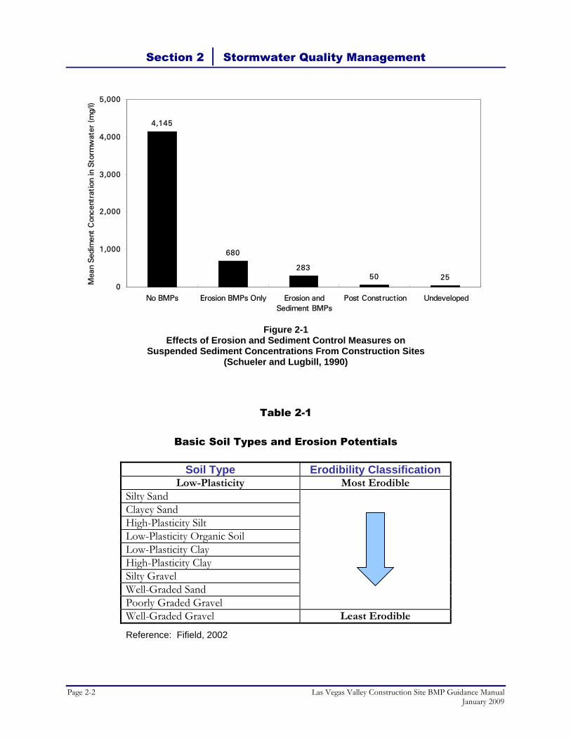
Erosion control practices focus on protecting soil surfaces and preventing the particles from being detached by wind or rain, whereas sediment control practices trap the soil particles after they have been dislodged and moved by wind or water (CA RWQCB, 1999). Erosion controls are generally considered more efficient and cost effective than sediment controls because they keep soils in place and do not require costly sediment removal and maintenance procedures. The combined use of these two BMPs is often required at construction sites to manage pollution in stormwater discharges. Maintaining natural drainage (preservation of vegetation, surface soils and grade) is the most effective means of filtering sediment and pollution and regulating the volume of runoff from land surfaces adjacent to streams (CA RWQCB, 1999). When it is not possible to maintain a natural state, sediment runoff from disturbed surfaces can be reduced significantly through the use of soil stabilization practices, sediment barriers and controls, and the stabilization of vehicle access roads. Some of these practices are temporary and only remain in effect during construction. Others are permanent and remain after construction is completed or until the site is stabilized or revegetated. Figure 2-1 provides a comparison of sediment concentrations in stormwater runoff discharged from sites with various levels of controls in place. The data in this figure were developed from watersheds with considerably more vegetation and lower natural sediment production rates than in the arid Las Vegas Valley, and thus benefits of construction site BMPs on sediment control are likely overstated for the Las Vegas Valley area. However, the same principles apply. Limiting the amount of disturbed soil area is also a critical component of an effective stormwater management program. Some agencies place limitations on the amount of total disturbed soil area each project can expose until either temporary or permanent erosion control measures are in place. Limitations on the amount of continuous disturbed soil area is also important, particularly on exposed slopes. Slope length and inclination are considered the most important criteria for soil stabilization and sediment controls, because these two factors have the largest potential impact on erosion rates. Slope lengths can be limited by installing measures that effectively break up the slope length, reduce runoff velocities and trap sediments. Terraces and linear sediment barriers such as fiber rolls can be implemented for this purpose. Different soil types and soil surface conditions also influence erosion potentials. Table 2-1 presents the erodibility classification of several different basic soil types. Soil erodibility is the propensity for soil particles to become detached by the erosive actions of water and wind. It is also a function of soil texture, organic matter content, soil structure and permeability.
Section 2 │ Stormwater Quality Management
Page 2-2 Las Vegas Valley Construction Site BMP Guidance Manual January 2009
4,145
680
28350 25
0
1,000
2,000
3,000
4,000
5,000
No BMPs Erosion BMPs Only Erosion andSediment BMPs
Post Construction Undeveloped
Mea
n S
edim
ent
Con
cent
rati
on in
Sto
rmw
ater
(m
g/l)
Figure 2-1 Effects of Erosion and Sediment Control Measures on
Suspended Sediment Concentrations From Construction Sites (Schueler and Lugbill, 1990)
Table 2-1
Basic Soil Types and Erosion Potentials
Soil Type Erodibility Classification Low-Plasticity Most Erodible
Silty Sand
Clayey Sand High-Plasticity Silt Low-Plasticity Organic Soil Low-Plasticity Clay High-Plasticity Clay Silty Gravel Well-Graded Sand Poorly Graded Gravel Well-Graded Gravel Least Erodible
Reference: Fifield, 2002
Section 2 │ Stormwater Quality Management
Las Vegas Valley Construction Site BMP Guidance Manual Page 2-3 January 2009
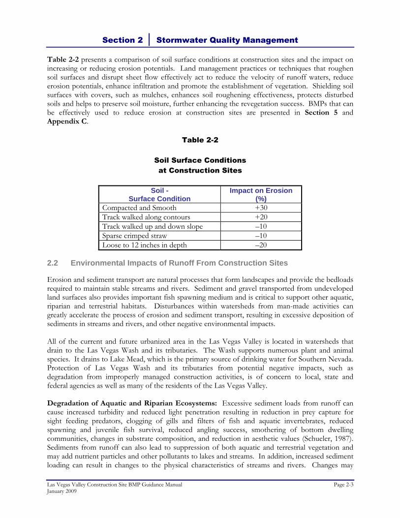
Table 2-2 presents a comparison of soil surface conditions at construction sites and the impact on increasing or reducing erosion potentials. Land management practices or techniques that roughen soil surfaces and disrupt sheet flow effectively act to reduce the velocity of runoff waters, reduce erosion potentials, enhance infiltration and promote the establishment of vegetation. Shielding soil surfaces with covers, such as mulches, enhances soil roughening effectiveness, protects disturbed soils and helps to preserve soil moisture, further enhancing the revegetation success. BMPs that can be effectively used to reduce erosion at construction sites are presented in Section 5 and Appendix C.
Table 2-2
Soil Surface Conditions at Construction Sites
Soil -
Surface Condition Impact on Erosion
(%) Compacted and Smooth +30 Track walked along contours +20 Track walked up and down slope –10 Sparse crimped straw –10 Loose to 12 inches in depth –20
2.2 Environmental Impacts of Runoff From Construction Sites
Erosion and sediment transport are natural processes that form landscapes and provide the bedloads required to maintain stable streams and rivers. Sediment and gravel transported from undeveloped land surfaces also provides important fish spawning medium and is critical to support other aquatic, riparian and terrestrial habitats. Disturbances within watersheds from man-made activities can greatly accelerate the process of erosion and sediment transport, resulting in excessive deposition of sediments in streams and rivers, and other negative environmental impacts. All of the current and future urbanized area in the Las Vegas Valley is located in watersheds that drain to the Las Vegas Wash and its tributaries. The Wash supports numerous plant and animal species. It drains to Lake Mead, which is the primary source of drinking water for Southern Nevada. Protection of Las Vegas Wash and its tributaries from potential negative impacts, such as degradation from improperly managed construction activities, is of concern to local, state and federal agencies as well as many of the residents of the Las Vegas Valley. Degradation of Aquatic and Riparian Ecosystems: Excessive sediment loads from runoff can cause increased turbidity and reduced light penetration resulting in reduction in prey capture for sight feeding predators, clogging of gills and filters of fish and aquatic invertebrates, reduced spawning and juvenile fish survival, reduced angling success, smothering of bottom dwelling communities, changes in substrate composition, and reduction in aesthetic values (Schueler, 1987). Sediments from runoff can also lead to suppression of both aquatic and terrestrial vegetation and may add nutrient particles and other pollutants to lakes and streams. In addition, increased sediment loading can result in changes to the physical characteristics of streams and rivers. Changes may

Section 2 │ Stormwater Quality Management
Page 2-4 Las Vegas Valley Construction Site BMP Guidance Manual January 2009
include streambed degradation, stream widening, and streambank erosion (Urban Drainage and Flood Control District, 1999). Pollution Transport: Sediment is a pollutant in its own right and can transport many substances such as nutrients, hydrocarbons, and trace metals, and lead to water pollution problems (APWA, 1981). Soil organic components, plant residues, nutrient elements, organic material, atmospheric pollutants, and liquid and solid wastes are pollutants that originate from topsoil losses. Construction activities remobilize pollutants in sediment and often add additional pollutants that adhere to the soil particles. Table 2-3 provides a list of the typical pollutants associated with construction site activities based on nationwide research.
2.3 Best Management Practices
A BMP can be defined as any program, technology, process, siting criteria, operating method, measure, or device that controls, prevents, removes, or reduces water pollution (IECA, 2002). Construction site BMPs are generally implemented to reduce or prevent erosion and to control the sediment and wastes that are generated from construction activities and transported in stormwater.
2.4 NPDES Permit Regulations
The NPDES program is a national permit program designed to regulate point source discharges to the waters of the United States. Stormwater discharge permits are required for certain activities by EPA regulations [40 CFR § 122.26(b)(14)]. In 1987, Congress amended the Federal Water Pollution Control Act (also known as the Clean Water Act) in order to protect receiving water bodies from the impacts of urban runoff. The amendments established a framework for regulating municipal and industrial discharges under the NPDES program. Sources of stormwater runoff that had the greatest potential to negatively impact water quality nationwide were addressed by Phase I of the NPDES Stormwater program. Construction sites are considered one of the 11 regulated industrial activities. Under Phase I, the EPA required NPDES permit coverage for stormwater discharges from medium and large MS4s located in incorporated places or counties with populations of 100,000 or more. In March 2003, Phase II of the NPDES Stormwater program took effect. In addition to requiring permit coverage for stormwater discharges from certain regulated small MS4s, Phase II lowered the threshold for construction activities regulation from 5 acres to 1 acre of land disturbance.

Section 2 │ Stormwater Quality Management
Las Vegas Valley Construction Site BMP Guidance Manual Page 2-5 January 2009
Table 2-3
Typical Construction Site Pollutants
Category Product / Activity Pollutants Adhesives Adhesives, Glues, Resins, Epoxy Synthetics
Calks, Sealers, Putty, Sealing Agents Coal Tars (Naptha, Pitch)
Phenolics, Formaldehydes Asbestos, Phenolics, Formaldehydes Benzene, Phenols, Napthalene
Cleaners Polishes (Metal, Ceramic, Tile), Etching Agents Cleaners, Ammonia, Lye, Caustic Sodas, and Bleaching Agents Chromate Salts
Metals Acidity/Alkalinity Chromium
Plumbing Solder (Lead, Tin), Flux (Zinc Chloride) Pipe Fitting (Cut Shavings) Galvanized Metals (Nails, Fences) Electric Writing
Lead, Copper, Zinc, Tin Copper Zinc Copper, Lead
Painting Paint Thinner, Acetone, MEK, Stripper Paints, Lacquers, Varnish, Enamels Turpentine, Gum Spirit, Solvents Sanding, Stripping Pigments, Dyes
Volatile Organic Compounds (VOCs) Metals, Phenolics, Mineral Spirits VOCs Metals Metals
Woods Sawdust Particle Board Dusts Treated Woods
Biological Oxygen Demand (BOD) Formaldehyde Copper, Creosote
Masonry and Concrete
Dusts (Brick, Cement) Colored Chalks (Pigments) Concrete Curing Compounds Glazing Compounds Cleaning Surfaces
Acidity, Sediments Metals Alkalinity Asbestos Acidity
Floors and Walls
Flashing Drywall Tile Cutting (Ceramic Dusts) Adhesives
Copper, Aluminium Sediments Minerals Phenolics, Formaldehydes
Remodelling and Demolition
Insulation Venting Systems Brick, Cement, Saw Cutting, Drywall
Asbestos Aluminium, Zinc Sediments
Air Conditioning and Heating
Insulation Coolant Reservoirs Adhesives
Asbestos Freon Phenolics, Formaldehydes
Yard O&M Vehicle and Machinery Maintenance Gasoline, Oils, Additives Marking Paints (Sprays) Grading, Earth Moving Portable Toilets Fire Hazard Control (Herbicides) Pest Control Wash Waters
Oils and Grease, Coolants Benzene and Derivatives, Oils and Grease Vinyl Chloride, Metals Sediments BOD, Disinfectants, pathogens Sodium Arsenite, Dinitro Compounds Rodenticides, Insecticides Herbicides, Concrete, Oils, Greases
Landscaping and Earthmoving
Planting, Plant Maintenance Excavation, Tiling Masonry and Concrete Solid Wastes (Trees, Shrubs, Green Waste, Mulch) Exposing Mineral Deposits Soils Additives Fertilizers
Pesticides, Herbicides, Nutrients Erosion (Sediments) Alkalinity BOD Acidity/Alkalinity, Metals Aluminium Sulfate, Sulfur Nutrients
Materials and Waste Storage
Waste Storage Hazardous Waste Containment Raw Material Piles
Used Oils, Solvents, Solid Waste See above categories See above categories
References: EPA, 1973: Meech and Bazany, 1991; Gosselin, et. al., 1984

Section 2 │ Stormwater Quality Management
Page 2-6 Las Vegas Valley Construction Site BMP Guidance Manual January 2009
2.5 Nevada’s General Permit for Construction Activity
In compliance with the NPDES program requirements, the NDEP has issued four baseline general permits. They are: (1) the Municipal Stormwater Runoff Permit, (2) the General Discharge Permit for Industrial Activity, (3) the General Discharge Permit for Mining Activity, and (4) the General Permit for Construction Activity. This BMP Guidance Manual applies to the Nevada Stormwater General Permit for Construction Activity (NVR100000). A copy of the permit in presented in Appendix A. The Nevada Stormwater General Permit for Construction Activity requires the owner/operator of all applicable private and public construction sites state-wide to submit to a Notice of Intent (NOI), pay an annual fee, and develop and implement a SWPPP that includes erosion, sediment and waste control measures and includes self-inspection, monitoring and reporting efforts. The SWPPP must be prepared prior to submittal of the NOI and is not to be submitted to NDEP, but must remain on the project site during the duration of the project. The annual fee is due when the NOI is initially filed and on July 1 every year. When construction is complete and all disturbed soils are stabilized, the site owner/operator is required to submit a Notice of Termination (NOT) to NDEP. Copies of NDEP’s NOI and NOT forms and a model SWPPP can be found on the NDEP Bureau of Water Pollution Control website at http://ndep.nv.gov/bwpc/index.htm. Phase II of the NPDES Stormwater program allows permitting authorities such as NDEP to waive requirements for small construction sites if the calculated value of the Rainfall Erosivity Factor for a site is less than 5 during the period of construction activity [40 CFR § 122.26 (b)(15)(i)(A)]. The worksheet to calculate the Rainfall Erosivity Factor (R) is available at NDEPs website http://ndep.nv.gov/bwpc/storm03.htm (Stormwater Resource Information - Small Construction Activity Waiver). If the project duration for a small site is relatively short or occurs during the first six months of the year, the calculated R for the site may be less than 5.
2.6 Projects Requiring Coverage Under NDEP’s General Permit
Construction activities that require permit coverage under NDEP’s 2008 General Permit for Construction Activity include the following:
• Any construction activity including clearing, grading, excavation, and demolition that disturbs 1 or more acres of land;
• Any land disturbance on a site that is part of a larger common plan of development or sale with a planned disturbance of 1 acre or greater;
• All temporary plants or operations set up to produce concrete, asphalt or other materials for a permitted construction project (does not apply to commercial operations or those that serve multiple projects);
• Any repaving operation of 1 or more acres that creates fine-grained sediments that are not immediately removed from the site and properly disposed of at an acceptable facility; and

Section 2 │ Stormwater Quality Management
Las Vegas Valley Construction Site BMP Guidance Manual Page 2-7 January 2009
• Any construction activity, including sites disturbing less than 1 acre, that are designated by NDEP or EPA to have a potential for contribution to a violation of a water quality standard or may significantly contribute pollutants to waters of the United States.
2.7 Permissible Non-Stormwater Discharges Under NDEP’s MS4 Permit
The following list contains non-stormwater discharges or flows that do not need to be regulated, unless they are identified as contributing pollutants to the storm drain system (EPA, 2000). This list is current as of the writing of this BMP Guidance Manual, however, the reader is directed to review the actual list contained within the MS4 permit for changes mandated by the EPA.
• Water line flushing • Landscape irrigation • Diverted stream flows • Rising ground waters and springs • Uncontaminated ground water infiltration into the storm drain system • Uncontaminated pumped ground water • Discharges from potable water sources • Foundation drains • Air conditioning condensation • Irrigation water • Lawn and garden watering • Water from crawl space pumps • Footing drains • Individual residential car washing • Flows from riparian habitats and wetlands • Dechlorinated swimming pool discharges • Street wash water • Discharges from fire-fighting activities • Fire sprinkler testing water
As noted above, some of these non-stormwater discharges or flows may require regulation, mitigation, or elimination if they contribute pollutants to the storm drain system. For example, it is not permissible to wash sediment tracked onto local roadways from a construction site into the storm drain system. Although discharges from fire-fighting activities may contain significant pollutant concentrations, this activity is relatively infrequent and is allowed to occur unregulated out of necessity to protect public health and safety.

Section 2 │ Stormwater Quality Management
Page 2-8 Las Vegas Valley Construction Site BMP Guidance Manual January 2009
2.8 References
American Public Works Association (APWA), Urban Stormwater Management, Special Report No. 49, American Public Works Association Research Foundation, 1981.
California Regional Water Quality Control Board (CA RWQCB), Erosion and Sediment Control Field
Manual, San Francisco Bay Area Region, Third Edition, July 1999. Fifield, J. S., Field Manual on Sediment and Erosion Control Best Management Practices for Contractors and
Inspectors, Forester Press, Santa Barbara, California, 2002. Goldman, S., K. Jackson, and T. Bursztynsky, Erosion and Sediment Control Manual, McGraw–Hill
Book Company, New York, New York, 1986. Gosselin, R., R. Smith, and H. Hodge, Clinical Toxicology of Commercial Products, Fifth Edition, Williams
and Wilkins, Baltimore/London, 1984. International Erosion Control Association (IECA), Workbook: How to Select, Install and Inspect
Construction Site Erosion and Sediment Control BMPs for NPDES Storm Water Permit Compliance, 2002.
Meech, M. and M. Bazany, Construction Creates Own Set of Hazardous Waste, Hazmat World. August,
1991. Schueler, T., Controlling Urban Runoff, A Practical Manual for Planning and Designing Urban BMPs,
July 1987. Schueler, T. and J. Lugbill, Performance of Current Sediment Control Measures at Maryland Construction Sites,
Occoquan Watershed Monitoring Lab and Metropolitan Washington Council of Governments. Washington, DC. 90 pp., 1990.
U. S. Environmental Protection Agency, Processes, Procedures, and Methods to Control Pollution Resulting
From Construction Activity, Office of Air and Water Programs, EPA 43079–73–007. October, 1973.
---- Stormwater Phase II Final Rule, Illicit Discharge Detection and Elimination Minimum Control Measure.
USEPA Office of Water, EPA 833–F00–007, Fact Sheet 2.5, January 2000 ---- Construction Site Storm Water Runoff Control, National Pollutant Discharge Elimination System, [on–line],
2002 at: http://cfpub.epa.gov/npdes/stormwater/menuofbmps/con_site.cfm Urban Drainage and Flood Control District, Urban Storm Drainage – Criteria Manual, Vol. 3 – Best
Management Practices, Denver, Colorado, September 1999.

Section 3The Las Vegas Valley
Construction Site Runoff Management Program

THIS PAGE LEFT BLANK INTENTIONALLY

Section 3.0 │ The Las Vegas Valley Construction Site Runoff Management Program
Las Vegas Valley Construction Site BMP Guidance Manual Page 3-1 January 2009
3.1 Local Conditions
The Las Vegas Valley watershed lies in the Mojave Desert of the Southwestern United States. Surface soil conditions and poor vegetation cover contribute to conditions of high natural erosion rates and sediment loads compared to other parts of the country. However, surface disturbance due to construction activities is believed to increase erosion and sediment transport over natural conditions, and has been identified by NDEP as a pollutant to be addressed by the MS4 Permittees. Sediment transport to, and deposition in, Las Vegas Wash and Lake Mead is a concern for agencies that manage these bodies of water. Pollutants that accompany the sediment load are of concern to Southern Nevada Water Authority (SNWA), which delivers drinking water from Lake Mead from a pump station intake near the Las Vegas Wash confluence. Local climatic conditions affect selection and design of construction site BMPs. Las Vegas Valley is the driest large MS4 community in the nation, with a mean annual rainfall of about 4.2 inches. Rainfall is infrequent, with an average of 15 days with measurable rainfall per year, and 11 days with a minimum of 0.10 inches of rainfall needed to produce significant runoff. Up to 0.20 inches of rainfall may be necessary to produce substantial runoff in undeveloped desert areas upstream of urban development. Isolated thunderstorms produce the heaviest rainfall, and typically cover only a few square miles for less than 6 hours. Las Vegas Valley continues to be one of the fastest growing urban areas in the nation, so construction site management programs will apply to a considerable area of future development. The majority of new development consists of housing and associated commercial development expanding from the existing urban center, and large hotel/casinos. The majority of significant redevelopment consists of new hotel/casinos and high-rise residential development in the vicinity of the Las Vegas Strip.
3.2 Local Program Requirements
The MS4 Permittees are responsible for developing, implementing, and enforcing a program to prevent pollutants from construction activities from entering their municipal storm drain systems. Per federal regulations (40 CFR § 122.26), the program must include the following elements:
• An ordinance or other regulatory mechanism to require erosion and sediment controls, as well as sanctions to ensure compliance, to the extent allowable under state or local law;
• Requirements for construction site operators to implement appropriate erosion and sediment control BMPs;
• Requirements for construction site operators to control wastes such as discarded building materials, concrete truck washout, chemicals, litter, and sanitary waste at construction sites that may cause adverse impacts to water quality;

Section 3.0 │ The Las Vegas Valley Construction Site Runoff Management Program
Page 3-2 Las Vegas Valley Construction Site BMP Guidance Manual January 2009
• Procedures for site plan review which incorporate consideration of potential water quality impacts;
• Procedures for receipt and consideration of information submitted by the public; and
• Procedures for site inspection and enforcement of control measures.
3.3 Legal Authority
The Cities of Las Vegas, North Las Vegas and Henderson and Clark County have adopted municipal codes and ordinances that grant them the authority to require BMPs to control erosion and sediment transport, prohibit materials and wastes from being deposited on streets and public places, prohibit non-stormwater discharges to the storm drain system, conduct inspections of industrial and commercial dischargers, and assess fees and fines. The MS4 Permittees have also adopted ordinances and practices that require permits for construction activities and a regulatory process for reviewing improvement plans, approving permits and inspecting construction sites for compliance. The permits for construction activities include grading, site development, building, and encroachment permits. Plans requiring review include tentative, final, parcel and subdivision maps, site plans, and drainage plans. The existing permitting and plan review process differs between the jurisdictions and is based on different governmental structures, ordinances, policies and procedures. Grading, which is the primary land disturbing construction activity, is currently regulated by the four jurisdictions under the ordinances presented in Table 3-1.
Table 3-1
Existing Grading Regulations
City of Las Vegas
City ofNorth Las Vegas City of Henderson
Clark County
Code Sections Municipal Code 16.24.080 (Plot and Grading Plans)
Municipal Code 17.28.040 (Procedure for Site Plan Approval)
Municipal Code 13 Municipal Code 30.32.040 (Grading Permit)
Requirements Drainage and Grading Permits
Drainage and Grading Permits
Floodplain Management
Drainage and Grading Permits
Although the regulation of grading and other types of earthwork construction varies between the four jurisdictions, their ordinances are consistent in requiring construction site operators to implement BMPs to control on-site erosion and sediment transport, and minimize discharges of sediment and other pollutants to the MS4. The ordinances require construction sites to properly manage construction materials and wastes so that they cannot be transported by stormwater runoff to the MS4. Implementation of BMPs is required at all construction sites that disturb a total area of 1 acre or greater. The BMPs must be implemented according to the performance standards noted in the following section of this BMP Guidance Manual.

Section 3.0 │ The Las Vegas Valley Construction Site Runoff Management Program
Las Vegas Valley Construction Site BMP Guidance Manual Page 3-3 January 2009
The application of uniform performance standards, together with the BMP specifications presented in Section 5.0 and Appendix C of this BMP Guidance Manual, provides the regulatory and technical parameters that must be met to implement construction site discharge control to the maximum extent practicable (MEP). The policies and procedures of the MS4 Permittees (presented in Section 3.5) are intended to provide the regulatory mechanism necessary to ensure these standards are implemented.
3.4 Performance Standards
The goal of the construction site runoff management program is to conduct all construction activities in a manner that effectively mitigates accelerated soil erosion, sediment transport and sediment deposition off-site and also manages construction materials and wastes to prevent or minimize their potential discharge from the site to the MEP. The BMPs selected by the construction site owner/operator shall meet all of the following standards.
1. Schedule construction activities to minimize the total amount of soil disturbed at any given time. Preserve native vegetation and surficial soils to the maximum extent practicable and conduct clearing and grading only in areas necessary for building activities and equipment traffic.
2. Establish temporary erosion and sediment transport control practices prior to construction activities.
3. Protect slopes susceptible to erosion by installing controls such as terraces, benches, retaining walls, temporary slope drains, fiber rolls, rolled erosion control products and vegetation.
4. Design and construct all temporary and permanent facilities that convey water around or through disturbed areas with slopes and control measures that limit the flow of water to non-erosive velocities.
5. Protect waterways within and bordering the site by installing buffers and temporary stream crossings. Protect natural drainages, storm drain channels and storm drain inlets in the vicinity of construction sites from disturbance, sedimentation and deposition of polluting materials such as construction site wastes.
6. Retain sediment caused by accelerated soil erosion from surface water before it leaves the site by installing BMPs such as temporary diversion dikes, silt fences, and v-ditches.
7. Remove sediment accumulated in BMPs at regular intervals and as soon as practicable after a stormwater runoff event. Sediment must be removed when BMP design capacity has been reduced by 50 percent.
8. Control construction site entrances and exits to minimize sediment deposition on roads to the maximum extent practicable.

Section 3.0 │ The Las Vegas Valley Construction Site Runoff Management Program
Page 3-4 Las Vegas Valley Construction Site BMP Guidance Manual January 2009
9. Do not store soil, aggregates, compost, construction materials or wastes on paved roadways.
10. Establish permanent stabilization practices on areas that have been disturbed as soon as practicable and no later than 14 days after construction activity in that portion of the site has temporarily or permanently ceased. This includes compliance with all dust control activities including those involving surface stabilization with dust palliatives. Some exceptions may apply; refer to the Nevada Stormwater General Permit for Construction Activity NVR100000, Section III.A.5.
11. Properly store construction site materials and manage wastes to prevent or minimize contact with stormwater and transport off-site. Construction site materials include, but are not limited to, petroleum products, paints, adhesives, and solvents. Construction site wastes include, but are not limited to, concrete washout, excess construction materials, empty storage containers, and litter.
12. Properly manage vehicle and equipment fuelling, maintenance, storage and parking areas to prevent and control leaks and spills. Properly manage the cleaning of vehicles and equipment to minimize discharge of wash water and pollutants to the MEP to the storm drain system, natural drainages or watercourses.
13. Establish permanent stabilization on all bare soils with perennial vegetative cover, rock mulch, or equivalent permanent stabilization measures upon completion of all site soil disturbing activities. Areas stabilized with vegetative cover must have a minimum density equivalent to 70 percent of the native background vegetative cover. Some exceptions may apply, refer to the Nevada Stormwater General Permit for Construction Activity NVR100000, Section IV.C.1. and 2.
If the project or site exhibits conditions that make achieving any of the objectives noted above infeasible, the contractor or other responsible party shall note those conditions in the Performance Standards Compliance Checklist (Appendix B) and provide the rationale for eliminating a standard.
3.5 Local Policies and Procedures
The MS4 Permittees have developed a regional approach to implementing a Construction Site Runoff Management Program in conjunction with local stakeholders. In addition to this regionally adopted BMP Guidance Manual, three procedural checklists will be consistently used by site operators and/or owners to assist the entities with the task of ensuring that BMPs are implemented at construction sites in accordance with the standards and specifications of this BMP Guidance Manual. The checklists will be used to address construction permit submittal requirements and plan review practices; performance standards compliance; and inspection, both by contractors and local government inspectors. The checklists developed to address these are the following:

Section 3.0 │ The Las Vegas Valley Construction Site Runoff Management Program
Las Vegas Valley Construction Site BMP Guidance Manual Page 3-5 January 2009
• Construction Permit Submittal Checklist • Performance Standards Compliance Checklist • Construction Site Inspection Checklist
Blank copies of these checklists are presented in Appendix B. Owners and/or operators may use their own Construction Site Inspection Checklist in place of the one developed for this BMP Guidance Manual, however, it must contain, at a minimum, all the information required by the checklist developed for this BMP Guidance Manual. These checklists represent the fundamental framework for the regional construction site discharge program. Each jurisdiction will individually be responsible for their own ordinances, implementing plan review, permitting, and inspection of construction sites.
3.5.1 Plan Review
The following regional plan review policies and procedures were developed after consultation with NDEP and stakeholders regarding the required contents of a local program. Additional plan review procedures may be implemented individually by each jurisdiction. The Construction Permit Submittal Checklist will be used by City and County staff to identify projects that will disturb 1 acre or larger. This includes all projects that may require a grading, site development, building, or encroachment permit (including public works projects). It may also be applied to plans requiring review, including final, parcel, and subdivision maps and site drainage plans. If the applicant indicates the total planned area of land disturbance will be 1 acre or more on the checklist, then they must submit a copy of their NOI submitted to NDEP and a copy of the letter of authorization from NDEP. If the applicant has not yet received the letter of authorization, a copy of the receipt for payment of the annual fee that is due at the time of filing is also acceptable. Once the applicant files the NOI and pays the annual fee, they are immediately covered under the Nevada Stormwater General Permit for Construction Activity. By submitting copies of the NOI, the letter of authorization or the receipt, completing and signing the checklist, the applicant acknowledges that they are aware of Nevada Stormwater General Permit for Construction Activity requirements, including the requirement to develop and implement a site specific SWPPP. The applicant further acknowledges that they are aware of this BMP Guidance Manual and the required performance standards noted above. A copy of the Performance Standards Compliance Checklist (discussed below) must be attached to the Construction Permit Submittal Checklist. In addition, the permit submittal checklist indicates that applicants must include five Standard Notes on all site plans for projects that disturb one or more acres. These Standard Notes are as follows:
1. Standard Note No. 1: The Owner, Site Developer, Contractor, and/or their authorized agents shall each day remove all sediment, mud, construction debris, or other potential pollutants that may have been discharged to, or accumulated in, the public rights of way of the ___________________________[insert applicable jurisdiction] as a result of construction activities associated with this site development or construction project. Such materials shall be prevented from entering the storm sewer system.

Section 3.0 │ The Las Vegas Valley Construction Site Runoff Management Program
Page 3-6 Las Vegas Valley Construction Site BMP Guidance Manual January 2009
2. Standard Note No. 2: Additional construction site discharge best management practices may be required of the owner and his or her agents due to unforeseen erosion problems or if the submitted plan does not meet the performance standards specified in the [insert jurisdiction’s ordinance reference] and the Las Vegas Valley Construction Site BMP Guidance Manual.
3. Standard Note No. 3: Temporary or permanent stabilization practices will be installed on disturbed areas as soon as practicable and no later than 14 days after the construction activity in that portion of the site has temporarily or permanently ceased. Some exceptions may apply; refer to the Nevada Stormwater General Permit for Construction Activity NVR100000, Section III.A.5.
4. Standard Note No. 4: At a minimum, the Contractor or his agent shall inspect all disturbed areas, areas used for storage of materials and equipment that are exposed to precipitation, vehicle entrance and exit locations, and all BMPs weekly, and within 24 hours after any rain event of 0.5 inches or more. The Contractor or his agent shall update or modify the Stormwater Pollution Prevention Plan as necessary. Some exceptions to weekly inspections may apply, such as suspension of land disturbance activities. Refer to the Nevada Stormwater General Permit for Construction Activity NVR100000, Section III.A.12.
5. Standard Note No. 5: Accumulated sediment in BMPs shall be removed within seven days after a stormwater runoff event or prior to the next anticipated storm event, whichever is earlier. Sediment must be removed when BMP design capacity has been reduced by 50 percent or more.
The MS4 Permittees may ask to see a copy of the SWPPP to ensure that one has been completed for the project site. However, the Cities and the County are not responsible for reviewing or approving SWPPPs. The Performance Standards Compliance Checklist will be submitted with the Construction Permit Submittal Checklist. Permit applicants and those that require plan reviews for proposed construction projects that will disturb 1 or more acres of land will use the checklist to establish a set of BMPs to meet the performance standards noted in Section 3.3. During the first visit to the site, inspectors will also review the applicant’s checklist to ensure that the set of BMPs selected fully meet all of the standards. The checklist indicates that the applicant must select at least one BMP to meet each performance standard (individual BMPs may satisfy more than one standard). It further indicates that the applicant is responsible for ensuring that the BMPs selected on the checklist are included in the contract bid documents. Finally, the checklist infers that some project sites may have characteristics that make meeting a performance standard infeasible or inapplicable (e.g., no steep slopes or no storm drain inlets at the site). If this occurs, the applicant is required to describe the specific site characteristics that prevent them from meeting a performance standard at the bottom of the form. In order to be effective, this checklist, together with the Construction Permit Submittal Checklist must be completed before permits are granted or plans are approved.

Section 3.0 │ The Las Vegas Valley Construction Site Runoff Management Program
Las Vegas Valley Construction Site BMP Guidance Manual Page 3-7 January 2009
3.5.2 Inspection and Enforcement
Construction site operators are encouraged to use a Construction Site Inspection Checklist (either their own or the one included with this BMP Guidance Manual) for the weekly and post storm self-inspections required under the Nevada Stormwater General Permit for Construction Activity. The MS4 Permittees will use the checklist included with this BMP Guidance Manual to ensure a consistent approach at conducting inspections and to verify that performance standards are being met. The Construction Site Inspection Checklist provided in Appendix B is intended for use by construction site operators who are required to conduct frequent inspections to ensure that site BMPs are installed and maintained appropriately. Construction site operators, or their qualified agents, should attach completed inspection checklists to their SWPPPs to provide documentation of their self-inspection efforts. Photo documentation of BMP installations and corrective actions is also recommended. Policies and procedures for the construction site inspection program by the MS4 Permittees will be established by each jurisdiction based on staffing levels, available resources, permit loads and distribution, measurable goals and the use of existing inspection programs. Inspection frequencies and administrative service charges may vary between the jurisdictions and may be based on site characteristics such as project size and duration. Enforcement policies and procedures have been established individually by each jurisdiction during the development of their stormwater quality management ordinance. The MS4 Permittees have all adopted a policy of obtaining compliance with the program rather than resorting to citations and fines. Their intent will be to work with contractors and site owners/operators to resolve problems and develop effective site management strategies. The typical order of enforcement policies and procedures used by the Las Vegas Valley communities includes the issuance of Notices of Violation (NOVs), cleanup and abatement orders, and/or work stoppages and fines. Sites that refuse to comply with local program requirements may also be referred to NDEP for further enforcement.
3.5.3 Public Reporting
The Cities and the County must respond to public reporting of questionable construction activities. Currently, the Cities’ Public Works and Utility Departments and the County’s Public Works Department, Public Response Office and Southern Nevada Health District receive and respond to complaints. Currently, illegal dumping of unknown substances at construction sites and discharges of non-stormwater substances to the storm drain system, other than those noted in Section 2.8, should immediately be reported to the appropriate city, Clark County Public Response Office or the Southern Nevada Health District.
3.5.4 Public Resources
The NDEP, Bureau of Water Pollution Control is the state agency responsible for issuing the Nevada Stormwater General Permit for Construction Activity, NV100000. As such, NDEP can provide assistance to contractors and design engineers with permit requirements, preparing SWPPPs and selecting the appropriate BMPs at construction sites. The NDEP website also provides a significant amount of information about the state and EPA stormwater programs, including digital

Section 3.0 │ The Las Vegas Valley Construction Site Runoff Management Program
Page 3-8 Las Vegas Valley Construction Site BMP Guidance Manual January 2009
versions of the Nevada Stormwater General Permit for Construction Activity, the NOI, the NOT, and the Small Construction Activity Waiver.
Nevada Division of Environmental Protection Bureau of Water Pollution Control 333 W. Nye Lane Room 129 Carson City, Nevada 89706-0851 Phone: (775) 687-9429 Fax: (775) 687-4684 Website: http://ndep.nv.gov/bwpc/storm03.htm
The Natural Resource Conservation Service (NRCS) is a division of the United States Department of Agriculture and its primary function in Nevada is to provide assistance to agricultural projects. However, the NRCS also provides local soil survey information to contractors and design engineers working on public and private construction projects.
Natural Resource Conservation Service 5301 Longley Lane Reno, Nevada 89502 Phone: (775) 784-5317 Fax: (775) 784-5939 Website: http://www.nrcs.usda.gov/
The State of Nevada has prepared a Best Management Practices Handbook containing guidance on a variety of rural and urban area BMPs. This manual can be found on the Nevada Division of Environmental Protection Bureau of Water Quality Planning (BWQP) website.
Section 4Stormwater Pollution Prevention Plans

THIS PAGE LEFT BLANK INTENTIONALLY

Section 4.0 │ Stormwater Pollution Prevention Plans
Las Vegas Valley Construction Site BMP Guidance Manual Page 4-1 January 2009
4.1 Who Must Prepare a SWPPP
The owners/operators of all proposed private and public construction sites that will disturb a total of 1 or more acres of land are required to obtain coverage under the Nevada Stormwater General Permit for Construction Activity NV100000. A list of the type of project activities requiring coverage under the Nevada Stormwater General Permit for Construction Activity is presented in Section 2.6. These same construction activities must comply with local stormwater ordinances that contain requirements for the implementation of BMPs to control stormwater and pollutant discharges from construction sites. To obtain permit coverage, the owners and/or operators of all applicable construction sites are required to develop and implement a SWPPP. The SWPPP is not a specific requirement of the local stormwater ordinances in Las Vegas Valley. However, it is a useful tool for documenting and tracking stormwater management practices throughout the life of active construction sites. Because the SWPPP as defined by NDEP can be a useful document for complying with local stormwater ordinances, information on SWPPP preparation based on NDEP guidance is provided in this section. Construction site owners/operators may use the SWPPP guidance provided by NDEP to prepare SWPPPs for construction activities in Las Vegas Valley. The Las Vegas Valley entities have not developed a separate SWPPP format for use within their regulated areas.
4.2 SWPPP Components
Per the Nevada Stormwater General Permit for Construction Activity, the SWPPP is to be prepared in accordance with good engineering practices and shall consist of the following components:
• A copy of the NOI submitted to NDEP;
• Project information such as the site location, type of project, the name and address of the owner and/or operator, the name and address of a contact person and the person responsible for implementing the plan;
• A description of all proposed and implemented major land disturbing activities;
• Estimates of the total area of the site and the area that will be disturbed;
• Estimates of pre- and post-construction runoff coefficients;
• A general location map and a detailed site map including drainage patterns, areas of soil disturbance, location of BMPs, borrow and equipment storage areas, potential receiving waters and a legend describing all map symbols used;
• Documentation of all proposed and implemented erosion, sediment and waste control measures, including a description of the permanent stormwater controls that will be built as part of the project;
• Documentation of all self-inspections, maintenance of BMPs, and corrective actions;

Section 4.0 │ Stormwater Pollution Prevention Plans
Page 4-2 Las Vegas Valley Construction Site BMP Guidance Manual January 2009
• Location and description of any non-stormwater discharges and stormwater discharges from dedicated asphalt and concrete plants located off-site;
• Certification by the owner/operator or authorized representative and all contractors who work on the construction site; and
• A copy of the Nevada Stormwater General Permit for Construction Activity requirements.
Each of the above elements must be revised as necessary to maintain accuracy if there are changes in design or construction of the project or the SWPPP is found to be insufficient.
4.3 Pre-Construction Site Assessment
Prior to commencing construction activities at a site, it is highly recommended that a site assessment be conducted to document the following existing conditions:
• Vegetation types and density; • Landforms, slopes and soil types; • Drainages, waterways and storm drain systems; • Existing structures, roadways, and disturbed areas; and • Historical soil and water quality data and land use information.
Section III.A.1.i of the Nevada Stormwater General Permit for Construction Activity indicates that data describing soil and the quality of any discharges from the site should be included in the SWPPP. In addition to this requirement, documentation of existing conditions can provide important baseline information that can be used to help develop the SWPPP, properly select BMPs, and establish final stabilization. General site soils information can be obtained from the NRCS (see Section 3.5.4) and the CCRFCD Hydrologic Criteria and Drainage Design Manual (HCDDM). The data collected from site or neighboring geotechnical investigations can also provide useful information. Photo documentation of existing vegetative cover can be very useful when attempting to establish final stabilization. The Nevada Stormwater General Permit for Construction Activity requires that a permanent perennial vegetative cover be established on all disturbed soils with a density equivalent to 70 percent of the pre-construction existing vegetative cover. Equivalent non-vegetative permanent stabilization measures can also be implemented. Final site stabilization is required prior to the owner/operator submitting an NOT to NDEP. Once the NOT is approved by NDEP, the owner/operator of the construction site is no longer responsible for any discharges that may occur at the site.
4.4 Runoff Coefficients and Discharge Rates
Section I.B.1a.(9) of the Nevada Stormwater General Permit for Construction Activity requires an estimate of the runoff coefficients for the site for both pre-construction and post-construction conditions (pre- and post-project). Runoff coefficients for different land uses are listed in CCRFCD’s HCDDM.
Section 4.0 │ Stormwater Pollution Prevention Plans
Las Vegas Valley Construction Site BMP Guidance Manual Page 4-3 January 2009
The HCDDM provides detailed descriptions of the methods to use for calculating composite runoff coefficients and for calculating discharges from the site (e.g., the Rational Method). The HCDDM should be referenced and its methods used whenever sizing BMPs such as temporary slope drains and sediment retention basins or storm drainage facilities such as underground pipes and culverts.
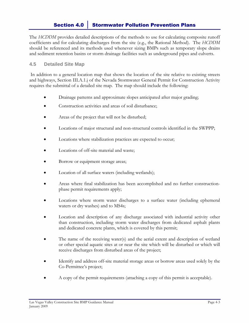
4.5 Detailed Site Map
In addition to a general location map that shows the location of the site relative to existing streets and highways, Section III.A.1.j of the Nevada Stormwater General Permit for Construction Activity requires the submittal of a detailed site map. The map should include the following:
• Drainage patterns and approximate slopes anticipated after major grading;
• Construction activities and areas of soil disturbance;
• Areas of the project that will not be disturbed;
• Locations of major structural and non-structural controls identified in the SWPPP;
• Locations where stabilization practices are expected to occur;
• Locations of off-site material and waste;
• Borrow or equipment storage areas;
• Location of all surface waters (including wetlands);
• Areas where final stabilization has been accomplished and no further construction-phase permit requirements apply;
• Locations where storm water discharges to a surface water (including ephemeral waters or dry washes) and to MS4s;
• Location and description of any discharge associated with industrial activity other than construction, including storm water discharges from dedicated asphalt plants and dedicated concrete plants, which is covered by this permit;
• The name of the receiving water(s) and the aerial extent and description of wetland or other special aquatic sites at or near the site which will be disturbed or which will receive discharges from disturbed areas of the project;
• Identify and address off-site material storage areas or borrow areas used solely by the Co-Permittee’s project;
• A copy of the permit requirements (attaching a copy of this permit is acceptable).
Section 4.0 │ Stormwater Pollution Prevention Plans
Page 4-4 Las Vegas Valley Construction Site BMP Guidance Manual January 2009
The location and type of BMPs that are proposed and actually implemented on the site should be identified on the site map using the map symbols provided in Section 5.3. A legend should be provided on the map defining the symbols used. As with the entire SWPPP, the site map should be considered a living document that is to be revised and updated when project design conditions change and BMPs are moved, changed or removed.
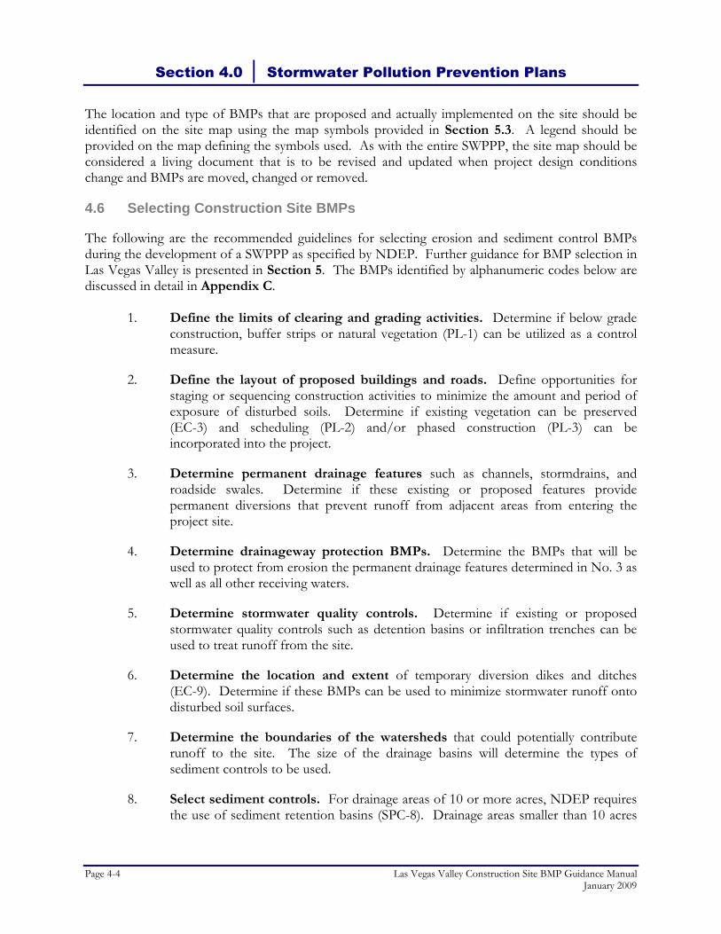
4.6 Selecting Construction Site BMPs
The following are the recommended guidelines for selecting erosion and sediment control BMPs during the development of a SWPPP as specified by NDEP. Further guidance for BMP selection in Las Vegas Valley is presented in Section 5. The BMPs identified by alphanumeric codes below are discussed in detail in Appendix C.
1. Define the limits of clearing and grading activities. Determine if below grade construction, buffer strips or natural vegetation (PL-1) can be utilized as a control measure.
2. Define the layout of proposed buildings and roads. Define opportunities for staging or sequencing construction activities to minimize the amount and period of exposure of disturbed soils. Determine if existing vegetation can be preserved (EC-3) and scheduling (PL-2) and/or phased construction (PL-3) can be incorporated into the project.
3. Determine permanent drainage features such as channels, stormdrains, and roadside swales. Determine if these existing or proposed features provide permanent diversions that prevent runoff from adjacent areas from entering the project site.
4. Determine drainageway protection BMPs. Determine the BMPs that will be used to protect from erosion the permanent drainage features determined in No. 3 as well as all other receiving waters.
5. Determine stormwater quality controls. Determine if existing or proposed stormwater quality controls such as detention basins or infiltration trenches can be used to treat runoff from the site.
6. Determine the location and extent of temporary diversion dikes and ditches (EC-9). Determine if these BMPs can be used to minimize stormwater runoff onto disturbed soil surfaces.
7. Determine the boundaries of the watersheds that could potentially contribute runoff to the site. The size of the drainage basins will determine the types of sediment controls to be used.
8. Select sediment controls. For drainage areas of 10 or more acres, NDEP requires the use of sediment retention basins (SPC-8). Drainage areas smaller than 10 acres

Section 4.0 │ Stormwater Pollution Prevention Plans
Las Vegas Valley Construction Site BMP Guidance Manual Page 4-5 January 2009
may utilize sediment retention basins or other sediment controls. The maximum drainage area for a temporary sediment retention basin is 20 acres.
9. Identify locations for topsoil and fill stockpiles. Define the stockpile management BMPs that will be used to minimize sediment transport from stockpiles during storm events.
10. Identify the location of temporary construction roads, entrances and exits. Determine the vehicle tracking controls (EC-5, EC-6, and SPC-11) that will be used to minimize the tracking of sediments off-site onto paved roadways.
11. Identify the location of equipment and material storage areas, and waste storage areas. Determine the General Site and Materials Management BMPs that will be used to minimize spills, contain wastes and prevent their contact with stormwater.
12. Select erosion controls. All exposed soils that will not be re-disturbed or covered with a structure will require control measures that will be based on the duration of exposure and the schedule of construction activities.
4.7 Consistency With Other Construction Plans
Per Section III.A.10 of the Nevada Stormwater General Permit for Construction Activity, the SWPPP must be consistent with all applicable construction plans and permits approved by state and local agencies. The SWPPP must be updated as necessary to remain consistent with any changes in other plans or permits that may impact surface water quality.
4.8 Inspection and Monitoring
Construction site operators or their qualified agents should use the Construction Site Inspection Checklist discussed in Section 3.5.2 and presented in Appendix B (or their own inspection checklist provided it contains, at a minimum, the same information) for site inspections. Section III.A.12 of the Nevada Stormwater General Permit for Construction Activity indicates that construction site inspections should occur by qualified personnel at least once every seven days and within 24 hours of a storm event of 0.5 inches or greater. Since storms in Las Vegas Valley often produce an uneven spatial distribution of precipitation, it can be difficult to determine actual precipitation totals at specific locations such as construction sites. Therefore, the Cities and the County recommend inspections be conducted within 24 hours of any rain event that creates runoff at the site. Areas that require inspection include the following:
• Disturbed areas that have not attained final stabilization;
• Material and equipment storage areas that are exposed to precipitation;
• All erosion and sediment control measures installed at the site and downstream of the site;

Section 4.0 │ Stormwater Pollution Prevention Plans
Page 4-6 Las Vegas Valley Construction Site BMP Guidance Manual January 2009
• All structural control measures; and
• All locations where vehicles enter and/or exit the site. BMPs should be inspected at regular intervals to ensure they are installed and maintained appropriately. Construction site operators, or their qualified agents, should attach completed inspection checklists to their SWPPPs to provide documentation of their self-inspection efforts. Photo documentation of BMP installations and corrective actions is also recommended.
4.9 Potential Enforcement Actions
As noted in Section 3.2, the MS4 Permittees have established enforcement policies and procedures during the development of their stormwater quality management ordinances. The intent of the local entities is to work with construction site contractors and owners/operators to gain compliance with the stormwater regulations.
4.10 Records Retention
The SWPPP and all records and data produced to comply with the Nevada Stormwater General Permit for Stormwater Activity must be retained by the owner/operator for a minimum of three years after issuance of a NOT. NDEP may require a longer period of records retention for some sites. Local Las Vegas Valley entities do not have their own records retention requirements for SWPPPs.
4.11 References and Websites
U. S. Environmental Protection Agency, Storm Water Management for Construction Activities, Developing Pollution Prevention Plans and Best Management Practices, Summary Guidance, Office of Water, EPA 833–R–92–001, October 1992.
Nevada Division of Environmental Protection, Bureau of Water Pollution Control Stormwater Discharge Permits http://ndep.nv.gov/bwpc/storm01.htm provides links to the following documents:
• NDEP’s NOI • NDEP’s NOT
Storm Water Resource Information http://ndep.nv.gov/bwpc/storm03.htm provides links to the following documents and websites:
• The Federal Stormwater Program, Frequently Asked Questions
• State BMP Manuals
• State BMP Fact Sheets

Section 4.0 │ Stormwater Pollution Prevention Plans
Las Vegas Valley Construction Site BMP Guidance Manual Page 4-7 January 2009
• State Stormwater Pollution Prevention Plan - Example
• NDEP Fact Sheet - General Permit for Stormwater Discharges Associated with Construction
• Nevada Stormwater General Permit for Construction Activity NVR100000
• Stormwater Pollution Prevention Plan Checklist
• Small Construction Activity Waiver
• EPA’s Stormwater Program Website

THIS PAGE LEFT BLANK INTENTIONALLY

Section 5 Preferred Best Management Practices

THIS PAGE LEFT BLANK INTENTIONALLY
Section 5.0 │ Preferred Best Management Practices
Las Vegas Valley Construction Site BMP Guidance Manual Page 5-1 January 2009
5.1 Introduction
Section 5 is intended only as technical guidance for the selection and implementation of BMPs. Any Flood Control District policies or standards are specifically outlined in the Clark County Regional Flood Control District’s HCDDM. It is recommended that a registered Professional Landscape Architect (PLA), Professional Engineer (PE), Certified Professional in Erosion and Sediment Control (CPESC), or a Certified Professional in Stormwater Quality (CPSWQ) design or review the specification and sizing criteria of any of the BMPs. Such a registered or certified professional should also review the site plans, and ultimately the SWPPP containing the BMPs. Also, it is recommended that the SWPPP designer conduct a site visit prior to beginning the BMP selection process. BMPs are defined as nonstructural and structural practices which, when properly implemented, operated, and maintained, provide the most efficient and practical means of reducing or preventing stormwater pollution to the MEP. The BMPs presented in Appendix C of this BMP Guidance Manual provide effective methods to control stormwater pollution, but are by no means all-inclusive. New and creative methods of controlling pollution are continuously generated by owners and contractors. However, it is required that the contractor monitor and prove the effectiveness of a new BMP before including it in a SWPPP. The local entity will require documentation of the effectiveness and design criteria for proposed BMPs that are not contained in this BMP Guidance Manual.
5.2 Selection Matrix
Selection of the most appropriate combination of BMPs for a specific construction site should be based upon a careful review of the conditions of the site for its potential for erosion, sediment transport, and stormwater runoff contamination. These potential problem areas are:
1. Steep slopes 2. Soil mounds and material stockpiles 3. Excavated areas (trenches, pits, etc.) 4. Perimeter and access areas 5. Drain inlets 6. Channels or medians 7. Equipment storage and maintenance areas 8. Debris management, cleanup, and washout 9. Landscaping and vegetation
For each of the nine potential problem areas, there is often more than one BMP available to effectively reduce the volume and velocity of stormwater runoff, the amount of the site exposed to erosion, and the potential for stormwater runoff pollution. As shown in the Selection Matrix (Figure 5-1), BMPs are organized into four main groups: planning (PL), erosion control (EC), sediment and pollutant control (SPC), and general housekeeping (GH). The first group (PL) is proactive, and includes strategies for organizing the construction process in a way that minimizes exposure of disturbed areas to rainfall. The second group (EC) is also preventative; controlling erosion at its source. The third (SPC) treats runoff to remove transported sediment and other associated stormwater pollutants. The fourth (GH) is less structural in nature and addresses
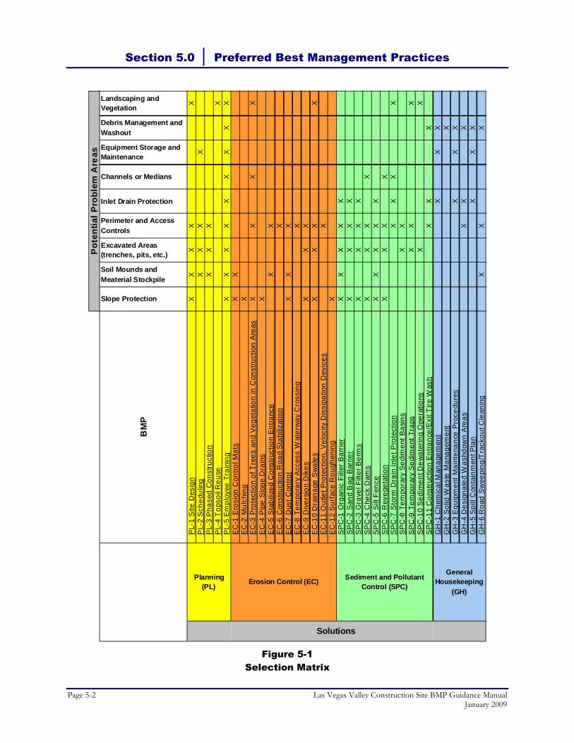
Section 5.0 │ Preferred Best Management Practices
Page 5-2 Las Vegas Valley Construction Site BMP Guidance Manual January 2009
Figure 5-1 Selection Matrix
BM
P
Slope Protection
Soil Mounds and Meaterial Stockpile
Excavated Areas (trenches, pits, etc.)
Perimeter and Access Controls
Inlet Drain Protection
Channels or Medians
Equipment Storage and Maintenance
Debris Management and Washout
Landscaping and Vegetation
PL-
1 S
ite D
esig
nX
XX
XX
PL-
2 S
ched
ulin
gX
XX
XP
L-3
Pha
sed
Con
stru
ctio
nX
XX
PL-
4 T
opso
il R
euse
XP
L-5
Em
ploy
ee T
rain
ing
XX
XX
XX
XX
XE
C-1
Ero
sion
Con
trol M
ats
XX
EC
-2 M
ulch
ing
XE
C-3
Pro
tect
ion
of T
rees
and
Veg
etat
ion
in C
onst
ruct
ion
Are
asX
XX
XE
C-4
Pip
e S
lope
Dra
ins
XE
C-5
Sta
biliz
ed C
onst
ruct
ion
Ent
ranc
eX
XE
C-6
Con
stru
ctio
n R
oad
Sta
biliz
atio
nX
EC
-7 D
ust C
ontro
lX
XX
EC
-8 T
empo
rary
Acc
ess
Wat
erw
ay C
ross
ing
XE
C-9
Div
ersi
on D
ikes
XX
XE
C-1
0 D
rain
age
Sw
ales
XX
XX
EC
-11
Out
let P
rote
ctio
n, V
eloc
ity D
issi
patio
n D
evic
esX
EC
-12
Sur
face
Rou
ghen
ing
XS
PC
-1 O
rgan
ic F
ilter
Bar
rier
XX
XX
XS
PC
-2 S
and
Bag
Bar
rier
XX
XX
SP
C-3
Gra
vel F
ilter
Ber
ms
XX
XX
SP
C-4
Che
ck D
ams
XX
XX
SP
C-5
Silt
Fen
ceX
XX
XX
SP
C-6
Rev
eget
atio
nX
XX
XS
PC
-7 S
torm
Dra
in In
let P
rote
ctio
nX
XX
XS
PC
-8 T
empo
rary
Sed
imen
t Bas
ins
XX
SP
C-9
Tem
pora
ry S
edim
ent T
raps
XX
XS
PC
-10
Sed
imen
t Dew
ater
ing
Ope
ratio
nsX
XS
PC
-11
Con
stru
ctio
n E
ntra
nce/
Exi
t Tire
Was
hX
XX
GH
-1 C
hem
ical
Man
agem
ent
XX
XG
H-2
Sol
id W
aste
Man
agem
ent
XG
H-3
Equ
ipm
ent M
aint
enan
ce P
roce
dure
sX
XX
GH
-4 D
esig
nate
d W
ashd
own
Are
asX
XX
GH
-5 S
pill
Con
tain
men
t Pla
nX
XX
GH
-6 R
oad
Sw
eepi
ng/T
rack
out C
lean
ing
XX
X
Solutions
Pot
entia
l Pro
blem
Are
as
Sediment and Pollutant Control (SPC)
Erosion Control (EC)General
Housekeeping (GH)
Planning (PL)

Section 5.0 │ Preferred Best Management Practices
Las Vegas Valley Construction Site BMP Guidance Manual Page 5-3 January 2009
operations and maintenance activities. Each BMP is cross-referenced to the potential problem area for which the individual BMPs applies. Many of the BMPs achieve control in more than one category, which should be taken into account when selecting BMPs for maximum effectiveness. The contractor should select the control practices that are best suited to the site, then select from suggested BMPs based upon consideration of cost, material availability, topography, location, and duration of exposure. Each of the BMP fact sheets in Appendix C has a “Ratings” table, which rates the associated costs and the target pollutants removal efficiency as high (H), moderate (M), or low (L). In selecting BMPs suitable for a site and developing a SWPPP, a five-step selection process may be used. A discussion of this step-by-step approach follows. Regardless of the type of BMP selected, the following policies should be followed in design and installation:
• Construction BMPs should not be placed in public streets or other public rights-of-way, but should be placed within the boundaries of the construction site.
• Construction BMPs should not adversely affect the drainage performance of permanent or temporary drainage facilities.
• Construction BMPs should not be located within the 100-year floodplain of washes, channels, and other flood control facilities.
5.3 BMP Map Symbols
Table 5-1 presents the BMP map symbols that should be consistently used on SWPPP site maps and other site plans that depict erosion, sediment and waste controls. Use of these simple codes and/or symbols is intended to provide a universally convenient method for depicting BMPs on site plans and other construction plans.
Table 5-1
BMP Map Symbols
BMP Number BMP Name BMP Map Symbol EC-1 Erosion Control Mats
EC-2 Mulching
ECM
ECM

Section 5.0 │ Preferred Best Management Practices
Page 5-4 Las Vegas Valley Construction Site BMP Guidance Manual January 2009
Table 5-1 (Continued)
BMP Map Symbols
BMP Number BMP Name BMP Map Symbol EC-3 Protection of Trees and Vegetation in Construction Areas
EC-4 Pipe Slope Drains
EC-5 Stabilized Construction Entrance
EC-6 Construction Road Stabilization
EC-7 Dust Control
EC-8 Temporary Access Waterway Crossing
EC-9 Diversion Dikes
EC-10 Drainage Swales
EC-11 Outlet Protection, Velocity Dissipation Devices
EC-12 Surface Roughening
PSD
PSD
DC
DC
SR
SR

Section 5.0 │ Preferred Best Management Practices
Las Vegas Valley Construction Site BMP Guidance Manual Page 5-5 January 2009
Table 5-1 (Continued)
BMP Map Symbols
BMP Number BMP Name BMP Map Symbol SPC-1 Organic Filter Barrier
SPC-2 Sand Bag Barrier
SPC-3 Gravel Filter Berms
SPC-4 Check Dams
SPC-5 Silt Fence
SPC-6 Revegetation
SPC-7 Storm Drain Inlet Protection (Only allowed on private development properties in the Las Vegas Valley)
orSPC-8 Temporary Sediment Basins
SPC-9 Temporary Sediment Traps
SPC-10 Sediment Dewatering Operations
RVG
RVG
CD
CD
SBB
SBB
GFB
GFB
OFB
OFB

Section 5.0 │ Preferred Best Management Practices
Page 5-6 Las Vegas Valley Construction Site BMP Guidance Manual January 2009
Table 5-1 (Continued)
BMP Map Symbols
BMP Number BMP Name BMP Map Symbol SPC-11 Construction Entrance/Exit Tire Wash
GH-1 Chemical Management
GH-2 Solid Waste Management
SWM
GH-3 Equipment Maintenance Procedures
GH-4 Designated Washdown Areas
GH-5 Spill Containment Plan
GH-6 Road Sweeping/Trackout Cleaning
5.4 Step 1: Construction Planning Scheduling
The first step in selecting BMPs is to compare the project schedule with onsite management measures that can limit the exposure of the project site to erosion. Consider the following strategies:
• Sequence construction activities so that disturbed areas are not exposed for long periods of time.
• Schedule landscaping and other work that permanently stabilizes the area to be done immediately after the land has been graded to its final contour.
• Alter the project schedule to minimize the amount of disturbed areas during the monsoon summer months of July and August, and the winter months of November, December, and January.
EMP
WD

Section 5.0 │ Preferred Best Management Practices
Las Vegas Valley Construction Site BMP Guidance Manual Page 5-7 January 2009
• Construct permanent stormwater control facilities early in the project schedule and then utilize these structures for controlling erosion and sedimentation both during and after the project. Common examples include converting temporary sediment traps and basins to permanent retention basins (sedimentation basins) and incorporating stabilization practices with the final landscaping plan.
5.5 Step 2: Erosion Control BMPs
The second step is to examine the site plan to determine appropriate methods for reducing the volume of stormwater which will run across the denuded areas of the project site. Limiting the exposure of graded areas to offsite runoff may involve vegetative and structural controls as well as onsite management options. To effectively determine appropriate volume control measures, the designer should visit the site and review a topographic map of the project site so that existing and proposed drainage patterns can be identified and temporary and permanent stormwater control structures can be located. Identify the following on the site map in the order listed:
1. Locations where stormwater enters and exits the site. Include both sheet and channel flow paths for the existing and final grading contours.
2. Approximate boundaries and estimated surface areas of each drainage area if the site has more than one drainage outlet.
3. Sensitive locations subject to high rates of erosion due to soil types, steep slopes, or unlined channels. Slopes over 100 feet in length are considered as areas of moderate to high erosion potential.
4. Categorize slopes as:
Slope (%)
Erosion Potential
0 - 5 Low 5 - 10 Moderate
Over 10 High
5. Construction entrances and exits, staging areas, and roads.
6. Areas where existing vegetation will not be disturbed by construction activity, and establish clearing limits.
7. Locations of permanent stormwater collection, drainage, and control structures.
With this information, consider the following methods for reducing the rate and volume of runoff affecting the construction site. Specific erosion control BMPs have been listed in Figure 5-1.

Section 5.0 │ Preferred Best Management Practices
Page 5-8 Las Vegas Valley Construction Site BMP Guidance Manual January 2009
5.5.1 Structural Controls
Structural controls aid in reducing runoff volumes. Examples of structural controls include:
• Constructing dikes and swales to divert upslope water from entering the unvegetated areas of the construction site;
• Using temporary dikes, swales, pipe slope drains to divert or intercept stormwater before it reaches long and/or steep slopes; and
• Releasing captured stormwater at a slow and controlled rate to prevent damage to downstream drainage ways and structures.
5.5.2 Vegetative Controls
Vegetative controls also aid in reducing runoff volumes although their application in the arid Las Vegas Valley climate is limited. Appropriate techniques include:
• Preserving vegetative cover and natural “desert pavement” to protect soil from direct impact of rainfall, where most erosion begins. Root systems hold soil particles and nutrients in place.
• Increasing the soil's ability to absorb moisture through vegetative means, surface roughening, and mulching (including gravel mulch).
Note: Soil stabilization BMPs must be consistent with dust control regulations and
measures.
Staging the grading schedule so that the native vegetation provides a buffer to slow and disperse runoff.
5.5.3 Runoff Velocity Reduction
Erosion control is greatly enhanced when the velocity of runoff is reduced in denuded areas, steep slopes, and drainage channels. Examples of velocity reduction practices include:
• Slope and overland controls
Limiting the length of slopes to 50 feet. Construct mid-slope diversion (swales) or straw wattles on longer slopes to intercept runoff.
Roughening slopes to increase the absorption of rainfall and slow runoff.
Limiting slopes to 3:1, where practical.
Preventing flows from becoming concentrated, wherever possible. Sheet flow is less erosive than concentrated channel flow.

Section 5.0 │ Preferred Best Management Practices
Las Vegas Valley Construction Site BMP Guidance Manual Page 5-9 January 2009
Protecting slopes with mulches, matting, or other types of temporary or permanent soil stabilization.
• Channel controls
Installing check dams in unlined drainage channels to slow runoff velocity and encourage settlement of sediments.
Providing velocity reducing structures such as riprap at stormwater outfalls.
Matching flow velocities to soil channel lining type per the CCRFCD HCDDM.
5.6 Step 3: Sediment and Pollutant Control BMPs
Once preventative measures have been implemented to control erosion through reduced soil exposure, runoff volume, and velocity (Section 5.5), the next priority is to treat stormwater to remove sediment and other suspended pollutants from the stormwater as much as possible before the water leaves the project site. Strategies for controlling sediment and pollutants include:
• Temporary sediment barriers such as silt fences, organic filter barriers, sand bag barriers, and gravel filter berms are appropriate for areas on construction sites with relatively flat slopes that produce sheet flow runoff.
• Directing sediment-laden stormwater to temporary sediment traps and basins via berms or channels. Onsite controls are only designed and sized for site runoff alone.
• Construct temporary sediment traps or basins at the drainage outlet for the site. When more than one basin is required due to the size of the site, construct these basins to operate in parallel.
• Protect downstream municipal storm drainage structures from sediment clogging by providing inlet protection for area drains and curb inlets and implement regular street sweeping. Note: Drain inlet protection measures should be placed within the construction site
boundary whenever possible. Local entities expressly prohibit installation of drain inlet BMPs in public rights-of-way.
5.7 Step 4: General Housekeeping BMPs
In conjunction with controlling erosion and sediment loading, practices must be implemented to prevent contamination of stormwater by materials other than sediment. As seen in Figure 5-1, there are several methods for preventing non-sediment stormwater pollution by construction materials, equipment, and wastes. Sometimes, the best housekeeping control is to manage potential pollutants offsite. For example, conducting equipment maintenance back at the maintenance shop rather than at the site will eliminate potential spills and contamination.
Section 5.0 │ Preferred Best Management Practices
Page 5-10 Las Vegas Valley Construction Site BMP Guidance Manual January 2009
5.8 Step 5: Review and Design the Proposed BMPs
After selecting the appropriate BMPs for a particular problem area on the site, the final step of the process is to review the site and site map for locations of all major structural and non-structural controls, and areas of permanent or temporary stabilization. The BMP fact sheets in Appendix C describe the appropriate applications, limitations, planning considerations, recommended standards and specifications, and recommended maintenance and inspection for each management practice. Additionally, it is important to keep the following points in mind:
• Flow diversions should not adversely impact offsite properties and the historic flow patterns should be maintained.
• BMPs should be designed and implemented for the Las Vegas Valley climate, which has the following characteristics:
An average of 13 rain events per year; between 0.1 - 0.5 inches per typical event and a cumulative annual rainfall of less than 5 inches. Maximum rainfall within a one-hour span is approximately 1.2 inches. (Western Regional Climate Center, www.wrcc.dri.edu).
Wind velocities range from 6.3 - 7.3 mph (important for dust control).
• In addition to the applicability and relative effectiveness of a BMP to a particular problem area, BMPs should also be selected based on the costs, including implementation, maintenance, and training.
Several erosion and pollutant control practices can be maintained on the developed site as permanent measures after the construction project has been completed. Refer to the Post Construction Methods section of each BMP fact sheet for detailed information. Note: Permanent diversion and settling basin structures are subject to the Drainage
Regulations, set forth by CCRFCD.
5.9 Notice of Termination
When a permitted construction site no longer has stormwater discharges associated with construction activity (as per 40 CFR § 122.26(b)(14)) or when the construction site operator is no longer the operator of the site, and NOT may be submitted to NDEP. The NOT form is available on the NDEP website (www.ndep.nv.gov) and includes information on the form to assist the construction site operator in determining when the NOT may submitted.

Appendix A Nevada Stormwater General Permit for
Construction Activity (NVR100000)

THIS PAGE LEFT BLANK INTENTIONALLY

Las Vegas Valley Construction Site BMP Guidance Manual January 2009
Appendix A
Nevada Stormwater General Permit for Construction Activity (NVR100000)

THIS PAGE LEFT BLANK INTENTIONALLY
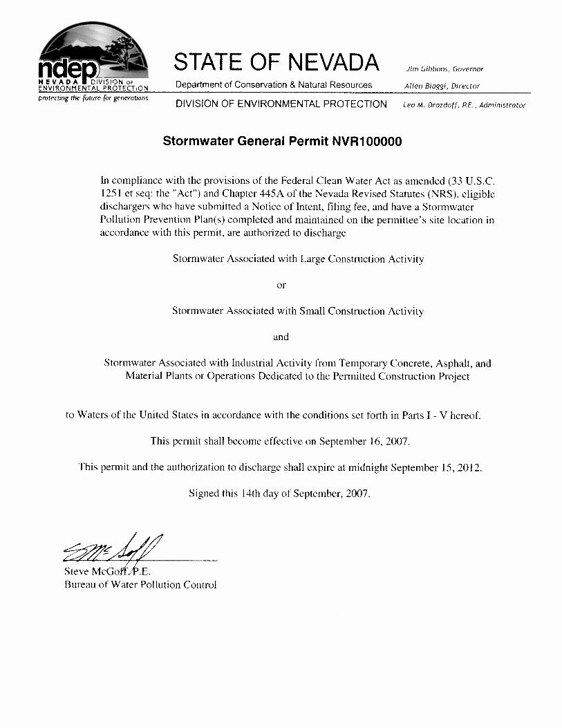

Stormwater General Permit NVR100000 Page 2 of 24 Nevada Division of Environmental Protection PART I. COVERAGE UNDER THIS GENERAL PERMIT
A. Permit Area. This General Permit covers the State of Nevada, except for Tribal Areas.1
B. Objective. The objective of this permit is to control and reduce pollution of Waters
of the U.S. (“WOUS”) from: Stormwater Discharges Associated with Large Construction Activity; Stormwater Discharges Associated with Small Construction Activity; and Stormwater Discharges Associated with Industrial Activity from temporary plants or operations set up to produce concrete, asphalt, or other materials for the permitted construction project; through the use of Best Management Practices (“BMPs”), as defined in Appendix A. In addition, BMPs shall include erosion and sediment controls, stormwater conveyance, stormwater diversion, and treatment structures, and any procedure or facility used to minimize the exposure of pollutants to stormwater or to remove pollutants from stormwater. Discharges to storm drain systems that in turn discharge to WOUS are considered to be discharges to WOUS.
C. Eligibility. This General Permit authorizes discharges from stormwater discharge
associated with large construction activity as defined in Appendix A, small construction activity as defined in Appendix A and industrial activities as defined in Appendix A provided the operator complies with all the requirements of this general permit and submits a Notice of Intent (“NOI”) in accordance with Part II of this general permit.
Any discharges that do not comply with the eligibility conditions of this permit are not authorized by the permit. A person must either apply for a separate National Pollutant Discharge Elimination System (“NPDES”) permit to cover the ineligible discharge(s), cease the discharge(s), or take the necessary steps to make the discharge(s) eligible for coverage under this permit.
D. Authorized Discharges 1. Allowable Stormwater Discharges. Subject to compliance with the terms and
conditions of this permit, an operator may discharge pollutants in: a. Discharges of stormwater runoff associated with construction activities as
defined in Appendix A; b. Discharges that are designated by NDEP as requiring a stormwater permit
under 40 CFR 122.26(a)(1)(v); 40 CFR 122.26(b)(15)(ii); or under 40 CFR 122.26(a)(9);
1 The State of Nevada, Division of Environmental Protection, Bureau of Water Pollution Control does not have permit authority for Tribal Lands. Construction discharge permits for Tribal Lands within the state must be acquired through EPA Region IX.

Stormwater General Permit NVR100000 Page 3 of 24 Nevada Division of Environmental Protection
c. Discharges from support activities(e.g. concrete or asphalt batch plants, equipment staging yards, material storage yards, excavated material disposal areas, borrow areas) provided:
i. The support activity is directly related to a construction site that is required to have NPDES permit coverage for discharges of stormwater associated with construction activity;
ii. The support activity is not a commercial operation serving multiple unrelated construction projects by different operators and does not operate beyond the completion of the construction activity at the last construction project it supports; and
iii. Appropriate controls and measures covering the discharges from the support activity areas are identified in a stormwater pollution prevention plan (“SWPPP”).
d. Non-stormwater discharges as noted in Part I.D.2 or as otherwise specifically allowed by the permit; and
e. Discharges comprised of a discharge listed in Part I (a) through (d) commingled with a discharge authorized by a different NDPES permit and/or discharge that does not require NPDES permit authorization.
2. Miscellaneous Non-Stormwater Discharges. An operator may discharge the
following non-stormwater discharges, provided they are not a significant source of pollutants and the operator implements appropriate BMPs to minimize pollutants discharged per Part III:
a. Discharges from fire-fighting activities. Although fire-fighting drainage
may contain significant pollutant concentrations, the frequency of discharge is low and the discharge and is hereby authorized out of necessity;
b. Fire hydrant flushing; c. Water used to wash vehicles where detergents are not used; d. Water used to control dust, provided effluent or other wastewaters are not
used; e. Potable water sources including water line flushing; f. Routine external building wash down where detergents are not used; g. Pavement wash waters where spills or leaks of toxic or hazardous
materials have not occurred (unless all spilled material has been removed) and where detergents are not used;
h. Uncontaminated air conditioning or compressor condensate; i. Uncontaminated groundwater or spring water; j. Foundation or footing drains where flows are not contaminated with
process materials such as solvents; k. Potable water well flushing where the receiving waters are ephemeral; l. Water used for compacting soil, provided effluent or other wastewaters are
not used;
Stormwater General Permit NVR100000 Page 4 of 24 Nevada Division of Environmental Protection
m. Water used for drilling and coring such as for evaluation of foundation materials, where flows are not contaminated with additives; and
n. Water obtained from dewatering operations of foundations in preparation for and during excavation and construction that will have flows of 300 gallons per minute (“gpm”) or less for thirty (30) days or less.
E. Limitations of Coverage
1. Post Construction Discharges. This permit does not authorize stormwater discharges that originate from the site after construction activities have been completed and the site, including any temporary support activity site, has undergone final stabilization. Post-construction stormwater discharges from industrial sites may need to be covered by a separate NPDES permit.
2. Prohibition on Discharges Mixed With Non-Stormwater. This permit does not authorize discharges that are mixed with sources of non-stormwater, except as allowed in Part I.D.
3. Discharges Covered by Another NPDES Permit. This general permit does not authorize stormwater discharges associated with construction activities that have been covered under an individual permit or have been required to obtain coverage under an alternative general permit. Construction discharges at mining operations are covered under the Mining General Permit NVR300000.
4. Discharges Threatening Water Quality. This general permit does not authorize discharges that will cause or contribute to non-attainment of water quality standards or to the designated use of receiving waters. The operator must design and implement BMPs sufficient to meet this requirement.
F. Waiver for Small Construction Activities. NDEP may exempt a small construction
operator from the requirement to obtain coverage under a stormwater permit, if certain criteria are met and proper application procedures followed.
1. Low Erosion Potential. If the small construction site is between 1 acre and 5
acres and the rainfall erosivity factor calculation (“R” in the Revised Universal Soil Loss Equation) is less than 5 during the entire period of construction activity, the site will be eligible for a waiver. The applicant must certify to NDEP that construction activity will occur only when R is less than 5. The erosivity factor can be calculated using NDEP’s NOI database.
The period of construction activity begins at initial earth disturbance and ends with the final site stabilization. The operator must submit a Permit Waiver electronically to NDEP in accordance with Part II of this permit before commencing construction activities in accordance with Part II.
Persons that are not required to file for permit coverage per this section must operate exempt construction sites in a manner that minimizes pollutants in the discharge. In the event discharges from the site may cause or contribute to non-

Stormwater General Permit NVR100000 Page 5 of 24 Nevada Division of Environmental Protection
attainment of water quality standards, NDEP may require the operator to obtain permit coverage.
Note: Construction activities that will disturb 5 acres or more cannot be exempted from stormwater permitting requirements. Also, construction activities less than 5 acres, but the parcel is part of a greater (5 acres or more) common plan of development or sale cannot be exempted.
G. Requirement for Individual Permit. NDEP may require the holder of a general
stormwater permit to apply for and obtain an individual permit in accordance with NAC 445A.269.
H. Requirement for Stormwater Permit for Projects Less Than 1 Acre. If NDEP
determines that a project less than one (1) acre in size will impact receiving waters or its tributaries within a 1/4-mile radius of the project, the owner of the project will be required to obtain a stormwater permit and abide by the terms of this permit.
I. Waiver for Certain Oil and Gas Operations. NDEP may not require a permit for
discharges of storm water runoff from construction operations at oil and gas exploration, production, processing or treatment operations or transmission facilities, composed entirely of flows which are from conveyances or systems of conveyances (including but not limited to pipes, conduits, ditches, and channels) used for collecting and conveying precipitation runoff and which are not contaminated by contact with or that has not come into contact with, any overburden, raw material, intermediate products, finished product, byproduct or waste products located on the site of such operations. A permit will be required if a stormwater discharge from a construction operation at an oil and/or gas exploration, production, processing, treatment, or transmission facility contributes to a violation of a water quality standard (except for discharges of sediment.)
PART II. REQUEST FOR INCLUSION UNDER THIS GENERAL PERMIT
A. Application for Coverage. A person may be authorized to discharge under this
general permit only if the stormwater discharge is associated with construction activities with the project site. An application seeking inclusion under this permit shall:
1. Submit a Notice of Intent (“NOI”) no later than two (2) days prior to the start of
construction. Eligible concrete, asphalt, and material plants or operations shall be included on the NOI submitted for the construction project. The site is covered provisionally under this permit once the NOI has been received electronically by NDEP and until approval of the permit by NDEP.
2. For each new NOI, the permittee must develop and implement a SWPPP that meets the requirements of Part III of this permit and covers either the entire site or
Stormwater General Permit NVR100000 Page 6 of 24 Nevada Division of Environmental Protection
all portions of the site for which the permittee is an operator. The SWPPP shall be prepared and maintained on the permittee’s project site for these discharges.
B. NOI Electronic Filing Requirements. NOI forms must be completed on-line at
NDEP’s website at the following address: http://ndep.nv.gov/bwpc/storm_cont03.htm. The applicant will be required to provide the following information to complete the NOI and submit it to NDEP:
1. Owner/operator (applicant) information including the name, address, city, state,
zip code and phone number of both the owner and operator; 2. Project/site information including the project name, project address/location, city,
state, zip code, latitude, longitude, at least one Assessor’s Parcel Number (“APN”) associated with the project and the county;
3. Name of the receiving water for any stormwater discharge; 4. The estimated construction start date; 5. The estimated completion date of construction; 6. An estimate of the area to be disturbed to the nearest acre; 7. An estimate of the likelihood of a stormwater discharge; 8. The address of the location where the SWPPP can be viewed including the city,
state, zip code and phone number. Note: It is not necessary to submit a copy of the SWPPP to NDEP.
C. Submitting the Completed NOI. After completing the NOI and filing it
electronically with NDEP, the applicant must perform the following steps within thirty (30) days to complete the NOI application: 1. Print out a copy of the NDEP confirmation page and sign below the certification
statement. The certification statement and the person responsible for signing the NOI is discussed in Part V of this permit;
2. Write a check to “NDEP” for the required permit fees; and 3. Mail the check and confirmation page with the original signature to:
Stormwater Coordinator Bureau of Water Pollution Control Nevada Division of Environmental Protection 901 S. Stewart Street, Suite 4001
Carson City NV 89701
D. Continuation of Coverage in the General Permit. To continue to be included in this general permit, holders of expired general permit NVR100000 must submit a renewal NOI to NDEP within ninety (90) days of the effective date of this permit to remain included under the original NOI. The permittee must verify that the information on the renewal NOI is valid and accurate before submitting the renewal NOI for continued inclusion. No additional filing fee is required to file this renewal NOI. In addition, the previously supplied permit identification number (CSW-xxxx) must be included with the submittal.

Stormwater General Permit NVR100000 Page 7 of 24 Nevada Division of Environmental Protection
E. Authorization Date of the Permit. The authorization date of the new permit shall
be:
1. The date the NOI is approved by NDEP; or 2. The effective date of this permit for all holders of expired general permit
NVR100000 that have submitted a renewal NOI for this permit; 3. An approval letter will be sent to the applicant stating the authorization date.
Special conditions may be included in the permit. 4. During the period beginning on the authorization date and lasting until permit
coverage is terminated, the permittee is authorized to discharge stormwater or approved non-stormwater to WOUS, as discussed in Part I.D. and in accordance with the SWPPP and the conditions listed in this permit.
PART III. STORM WATER POLLUTION PREVENTION PLAN
A. Objective. Prior to submitting the NOI and filing fee, the SWPPP shall be completed and available for inspection at the project site for each construction project and material plant or operation covered by this permit. The purpose of the SWPPP is to identify stormwater pollution sources, reduce their impacts, and comply with the conditions of this permit. The SWPPP shall be prepared in accordance with good engineering practices and shall consist of project information, BMPs, inspection and maintenance, controls for non-stormwater discharges, and a description of permanent stormwater controls that will be built as part of the project. Each of the plan elements must be revised as necessary to maintain accuracy if there are changes in design or construction of the project or if the SWPPP is found to be insufficient. NDEP may require modifications to a SWPPP within a specified time frame. The permittee shall make the SWPPPs available upon request to the State or local agency approving sediment and erosion plans, grading plans, or storm water management plans; local government officials; or the operator of a municipal separate storm sewer receiving discharges from the site. The SWPPP must be kept on-site or locally available and must be available for review by NDEP at the time of an on-site inspection. The SWPPP shall include the following minimum elements:
1. Project Description
a. Permittee information including the company or agency, street address,
city, state, zip code, and phone number; b. Contact information of the permittee including the name, street address,
city, state, zip code, and phone number; c. The name(s) of the person(s) responsible for implementation of the
SWPPP; d. The project name; e. The project location including the address, city, county and at least one
APN associated with the project;

Stormwater General Permit NVR100000 Page 8 of 24 Nevada Division of Environmental Protection
f. A description of the nature of the construction activity; g. A description of the intended sequence of major activities which disturb
soils for major portions of the site (e.g., grubbing, excavation, grading, utilities and infrastructure installation);
h. Estimates of the total area of the site and the total area of the site that is expected to be disturbed by excavation, grading, or other construction activities including offsite borrow and fill areas;
i. An estimate of the runoff coefficient of the site for both the preconstruction and post-construction conditions and data describing the soil or the quality of any discharge from the site;
j. A general location map of the project (e.g., a portion of a city or county map) and a site map of the project indicating the following:
i. Drainage patterns and approximate slopes anticipated after major
grading; ii. Construction activities and areas of soil disturbance;
iii. Areas of the project that will not be disturbed; iv. Locations of major structural and nonstructural controls
identified in the SWPPP; v. Locations where stabilization practices are expected to occur;
vi. Locations of off-site material and waste; vii. Borrow or equipment storage areas;
viii. Location of all surface waters (including wetlands); ix. Areas where final stabilization has been accomplished and no
further construction-phase permit requirements apply; x. Locations where storm water discharges to a surface water
(including ephemeral waters or dry washes) and to Municipal Separate Storm Sewer Systems (“MS4s”);
xi. Location and description of any discharge associated with industrial activity other than construction, including storm water discharges from dedicated asphalt plants and dedicated concrete plants, which is covered by this permit;
xii. The name of the receiving water(s) and the aerial extent and description of wetland or other special aquatic sites at or near the site which will be disturbed or which will receive discharges from disturbed areas of the project;
xiii. Identify and address offsite material storage areas or borrow areas used solely by the permittee’s project;
xiv. A copy of the permit requirements (attaching a copy of this permit is acceptable).
2. Stormwater Controls. Each SWPPP shall include a description of appropriate
control measures (i.e., BMPs) that will be implemented as part of the construction activity to control pollutants in storm water discharges. The SWPPP must clearly describe for each major activity identified in Part III.1.g: (a) Appropriate control

Stormwater General Permit NVR100000 Page 9 of 24 Nevada Division of Environmental Protection
measures and the general timing (or sequence) during the construction process that the measures will be implemented; and (b) which permittee is responsible for implementation.
3. Offsite Material Storage Areas. Offsite material storage areas (also including
overburden and stockpiles of dirt, borrow areas, etc.) used solely by the permitted project are considered a part of the project and must be addressed in the SWPPP.
4. Erosion and Sediment Controls. The SWPPP must describe the implementation
of control measures, including the following minimum components:
a. Design. The construction-phase erosion and sediment controls should be designed to retain sediment on site to the degree attainable.
b. Selection, Installation and Maintenance. All control measures must be
properly selected, installed, and maintained in accordance with the manufacturers’ specifications and good engineering practices. If periodic inspections or other information indicates a control has been used inappropriately, or incorrectly, the permittee must replace or modify the control for site situations, as soon as practicable and before the next storm event. If implementation prior to the next anticipated storm event is impracticable, maintenance must be scheduled and accomplished as soon as practicable.
c. Offsite Accumulation of Sediment. When sediment escapes the
construction site, off-site accumulations of sediment must be removed at a frequency sufficient to ensure no adverse effects on water quality (e.g., fugitive sediment in street could be washed into storm drains by the next rain and/or pose a safety hazard to users of public streets).
d. Good Housekeeping. The SWPPP must describe good housekeeping
procedures to prevent litter, construction debris, and construction chemicals exposed to stormwater from becoming a pollutant source for storm water discharges (e.g., screening outfalls, picked up daily).
5. Stabilization Practices.
a. Description and Schedule. The SWPPP must include a description of interim and permanent stabilization practices for the site, including a schedule of when the practices will be implemented. Site plans should ensure that existing vegetation is preserved where attainable and that disturbed portions of the site are stabilized. Stabilization practices may include but are not limited to: establishment of temporary vegetation, establishment of permanent vegetation, mulching, geotextiles, sod

Stormwater General Permit NVR100000 Page 10 of 24 Nevada Division of Environmental Protection
stabilization, vegetative buffer strips, protection of trees, preservation of mature vegetation, and other appropriate measures.
b. Records of Stabilization. The following records shall be maintained and
attached to the SWPPP: the dates when major grading activities occur; the dates when construction activities temporarily or permanently cease on a portion of the site; and the dates when stabilization measures are initiated.
c. Deadlines for Stabilization. Except as provided in Part III.A.5.c.(i), (ii),
and (iii) below, stabilization measures shall be initiated as soon as practicable in portions of the site where construction activities have temporarily or permanently ceased, but in no case more than fourteen (14) days after the construction activity in that portion of the site has temporarily or permanently ceased.
i. Where the initiation of stabilization measures by the fourteenth
(14th) day after construction activity temporary or permanently cease(s) is precluded by snow cover or frozen ground conditions, stabilization measures shall be initiated as soon as practicable.
ii. Where construction activity on a portion of the site is
temporarily ceased, and earth-disturbing activities will be resumed within twenty-one (21) days, temporary stabilization measures do not have to be initiated on that portion of site.
iii. In arid areas (areas with an average annual precipitation of 0 to
10 inches), semiarid areas (areas with an average annual precipitation of 10 to 20 inches), and areas experiencing droughts where the initiation of stabilization measures by the fourteenth (14th) day after construction activity has temporarily or permanently ceased is precluded by seasonal arid conditions, stabilization measures shall be initiated as soon as practicable.
6. Structural Practices. The SWPPP must include a description of structural
practices to divert flows from exposed soils, store flows or otherwise limit runoff and the discharge of pollutants from exposed areas of the site to the degree attainable. Structural practices may include but are not limited to: silt fences, earth dikes, drainage swales, sediment traps, check dams, subsurface drains, pipe slope drains, level spreaders, storm drain inlet protection, rock outlet protection, reinforced soil retaining systems, gabions, and temporary or permanent sediment basins. Placement of structural practices in floodplains should be avoided to the degree attainable. The installation of these devices may be subject to section 404 of the Clean Water Act (“CWA”). A combination of sediment and erosion control measures is required to achieve maximum pollutant removal.

Stormwater General Permit NVR100000 Page 11 of 24 Nevada Division of Environmental Protection
a. Sediment Basins.
i. For common drainage locations that serve an area with ten (10) or more acres disturbed at one time, a temporary (or permanent) sediment basin that provides storage for a calculated volume of runoff from a 2-year, 24-hour storm event from each disturbed acre drained, or equivalent control measures, shall be provided where attainable until final stabilization of the site. Where no such calculation has been performed, a temporary (or permanent) sediment basin providing 3,600 cubic feet of storage per acre drained, or equivalent control measures, shall be provided where attainable until final stabilization of the site. When computing the number of acres draining into a common location it is not necessary to include flows from offsite areas and flows from onsite areas that are either undisturbed or have undergone final stabilization where such flows are diverted around both the disturbed area and the sediment basin. In determining whether installing a sediment basin is attainable, the permittee may consider factors such as site soils, slope, available area on site, etc. In any event, the permittee must consider public safety, especially as it relates to children, as a design factor for the sediment basin and alternative sediment controls shall be used where site limitations would preclude a safe design.
ii. For drainage locations that serve ten (10) or more disturbed acres
at one time and where a temporary sediment basin or equivalent controls is not attainable, smaller sediment basins and/or sediment traps should be used. Where neither the sediment basin nor equivalent controls are attainable due to site limitations, silt fences, vegetative buffer strips, or equivalent sediment controls are required for all down slope boundaries of the construction area and for those side slope boundaries deemed appropriate as dictated by individual site conditions.
iii. For drainage locations serving less than ten (10) acres, smaller
sediment basins and/or sediment traps should be used. At a minimum, silt fences, vegetative buffer strips, or equivalent sediment controls are required for all down slope boundaries (and for those side slope boundaries deemed appropriate as dictated by individual site conditions) of the construction area unless a sediment basin providing storage for a calculated volume of runoff from a 2-year, 24-hour storm event or 3,600 cubic feet of storage per acre drained is provided.
b. Velocity Dissipation Devices.

Stormwater General Permit NVR100000 Page 12 of 24 Nevada Division of Environmental Protection
Velocity dissipation devices must be placed at discharge locations and along the length of any outfall channel to provide a non-erosive flow velocity from the structure to a water course so that the natural physical and biological characteristics and functions are maintained and protected (e.g. no significant changes in the hydrological regime of the receiving water).
7. Post-Construction Stormwater Management. The SWPPP must include a
description of stormwater management measures that will be installed during the construction process to control pollutants in stormwater discharges that will occur after construction operations have been completed. Structural measures should be placed on upland soils to the degree attainable. Such measures must be designed and installed consistent with applicable local or state stormwater management requirements.
Such practices may include but are not limited to: stormwater detention structures (including wet ponds); stormwater retention structures; flow attenuation by use of open vegetated swales and natural depressions; infiltration of runoff onsite; and sequential systems (which combine several practices). The SWPPP shall include an explanation of the technical basis used to select the practices to control pollution where flows exceed predevelopment levels.
Note: The installation of these devices may also require a separate permit under section 404 of the CWA. Permittees are only responsible for the installation and maintenance of stormwater management measures prior to final stabilization of the site, and are not responsible for maintenance after stormwater discharges associated with construction activity have been eliminated from the site. However, post construction stormwater BMPs that discharge pollutants from point sources once construction is completed may, in themselves, need authorization under a separate NPDES permit.
8. Non-Storm Water Discharge Maintenance. The SWPPP must identify all
allowable sources of non-stormwater discharges listed in Part I.D.2 of this permit, except for flows from fire fighting activities. Non-stormwater discharges are to be eliminated or reduced to extent possible. The operator must implement appropriate pollution prevention measures to minimize pollutants in any non-storm water component(s) of the discharge and must describe those measures in the SWPPP. Except if used in emergency firefighting, superchlorinated wastewaters must be held on-site until the chlorine dissipates, or otherwise dechlorinated prior to discharge.
9. Other Controls. The SWPPP must describe:
a. Measures to prevent the discharge of solid materials, including building

Stormwater General Permit NVR100000 Page 13 of 24 Nevada Division of Environmental Protection
materials, to WOUS, except as authorized by a permit issued under section 404 of the CWA;
b. Measures to minimize off-site vehicle tracking of sediments, to the extent
practicable, and the generation of on-site dust;
c. Measures to sufficiently stabilize soil at culvert locations to prevent the formation of rills and gullies during construction;
d. A description of construction and waste materials expected to be stored
on-site with updates as appropriate. The SWPPP shall also include a description of controls to reduce pollutants from these materials including storage practices to minimize exposure of the materials to stormwater, and spill prevention and response; and
e. A description of pollutant sources from areas other than construction
(including stormwater discharges from dedicated asphalt plants and dedicated concrete plants), and a description of controls and measures that will be implemented at those sites to minimize pollutant discharges.
10. Applicable Federal, State, or Local Programs.
a. The SWPPP shall be consistent with applicable State, and/or local waste disposal, sanitary sewer or septic system regulations to the extent these are located within the permitted area;
b. When discharges to water quality-impaired waters that are contained in
the current 303(d) Impaired Water Body listing issued by the Nevada Division of Environmental Protection, Bureau of Water Quality Planning, the permittee must investigate whether discharges from the permittee’s site will contribute significantly to any 303(d) listing, and when the permittee discharges into a water body with an established Total Maximum Daily Load (“TMDL”), the permittee shall comply with all applicable TMDL requirements. This information can be found on the following NDEP website: http://ndep.nv.gov/bwqp/standard.htm.
When a TMDL has not been established as described in paragraph above, the permittee must include a section in the SWPPP describing the condition for which the water has been listed. The SWPPP must also include a demonstration that the BMPs that are selected for implementation will be sufficient to ensure that the discharges will not cause or contribute to an exceedance of an applicable State water quality standard;
c. Permittees that discharge storm water associated with construction
Stormwater General Permit NVR100000 Page 14 of 24 Nevada Division of Environmental Protection
activities must ensure their SWPPP is consistent with requirements specified in applicable sediment and erosion site plans or site permits, or stormwater management site plans or site permits approved by State or local officials;
d. SWPPPs must be updated as necessary to remain consistent with any
changes applicable to protecting surface water resources in sediment and erosion site plans or site permits, or stormwater management site plans or site permits approved by State or local officials for which the permittee receives written notice; and
e. The SWPP may incorporate by reference the appropriate elements of plans
required by other agencies. A copy of the requirements incorporated by reference shall be included as an attachment to the SWPPP.
11. Maintenance of BMPs
a. All erosion and sediment control measures and other protective measures
identified in the SWPPP must be maintained in effective operating condition. If site inspections required by Part III.A.12 identify BMPs that are not operating effectively or if the capacity has been reduced by 50%, maintenance shall be performed before the next anticipated storm event, or as soon as possible if maintenance before the next anticipated storm event is not practicable;
b. If existing BMPs need to be modified or additional BMPs are necessary,
implementation must be completed before the next anticipated storm event. If implementation prior to the next anticipated storm event is impracticable, maintenance must be scheduled and accomplished as soon as practicable; and
c. The permittee must remove sediment from sediment traps or
sedimentation ponds when design capacity has been reduced by 50%.
12. Construction Site Inspections
a. Routine Inspection Schedule. The permittee must ensure routine inspections are performed at the site to ensure the BMPs are functional and that the SWPPP is being properly implemented. The permittee must have the site inspected at least once every seven (7) calendar days and within 24 hours of the end of a storm event of 0.5 inches or greater;
b. Inspection Waiver. Permittees are eligible for a waiver of weekly
inspection requirements until one month before thawing conditions are expected to result in a discharge if all of the following requirements are

Stormwater General Permit NVR100000 Page 15 of 24 Nevada Division of Environmental Protection
met:
i. The project is located in an area where frozen conditions are anticipated to continue for extended periods of time (i.e., more than one month);
ii. Land disturbance activities have been suspended; and iii. The beginning and ending dates of the waiver period are
documented in the SWPPP.
c. Inspectors. Qualified personnel (provided by the permittee or cooperatively by multiple permittees) shall inspect disturbed areas of the construction site that have not been finally stabilized, areas used for storage of materials that are exposed to precipitation, structural control measures, and locations where vehicles enter or exit the site. “Qualified personnel” means a person knowledgeable in the principles and practice of erosion and sediment controls and who possesses the skills to assess conditions at the site that could impact stormwater quality and the effectiveness of the BMPs selected to control the quality of the stormwater discharges;
d. Scope of Inspections. Inspections must include all areas of the site
disturbed by construction activity and areas used for storage of materials that are exposed to precipitation. Inspectors must look for evidence of, or the potential for, pollutants entering the drainage system. Sediment and erosion control measures identified in the SWPPP shall be observed to ensure that they are operating correctly. Where discharge locations or points are accessible, they shall be inspected to ascertain whether sediment and erosion control measures are effective in preventing significant impacts to receiving waters. Where discharge locations are inaccessible, nearby downstream locations shall be inspected to the extent that such inspections are practicable. Locations where vehicles enter or exit the site shall be inspected for evidence of offsite sediment tracking. All BMPs and areas inspected and their condition must be documented in the inspection report;
e. Inspection Report. An inspection report summarizing the scope of the
inspection, name(s) and qualifications of personnel making the inspection, the date(s) of the inspection, and major observations relating to the implementation of the SWPPP shall be made. Major observations should include the location(s) of discharges of sediment or other pollutants from the site; location(s) of BMPs that need to be maintained; location(s) of BMPs that failed to operate as designed or proved inadequate for a particular location; and location(s) where additional BMPs are needed that did not exist at the time of inspection;

Stormwater General Permit NVR100000 Page 16 of 24 Nevada Division of Environmental Protection
f. Maintaining Inspection Records. The permittee must ensure that the inspection reports and record of any follow-up actions taken in accordance with Part III.A.12.e of this permit is retained as part of the SWPPP for at least three years from the date that permit coverage expires or the site is finally stabilized. Inspection reports shall identify any incidents of noncompliance with this permit. Where a report does not identify any incidents of noncompliance, the report shall contain a certification that the facility is in compliance with the SWPPP and this permit. The report shall be signed in accordance with Part V.B.1 of this permit;
g. Follow-Up Actions. Based on the results of the inspection, the SWPPP
shall be modified as necessary (e.g., show additional controls on a map required by Part III.A.1.j and/or revise the description of controls required by Part III.A.2) to include additional or modified BMPs designed to correct problems identified. Revisions to the SWPPP shall be completed within seven (7) calendar days following the inspection. If existing BMPs need to be modified or if additional BMPs are necessary, implementation shall be completed within 7 days following receipt of the inspection results or prior to the next anticipated storm event, whenever practicable. If implementation of the BMPs before the next storm event is impracticable, the BMPs shall be implemented as soon as possible if implementation before the next anticipated storm event is not practicable.
13. Maintaining an Updated SWPPP. The operator must amend the SWPPP within
seven (7) business days whenever:
a. There is a change in design, construction, operation, or maintenance at the construction site that has a significant effect on the discharge of pollutants to WOUS that has not been previously addressed in the SWPPP; or
b. During inspections, monitoring if required, or investigations by the
permittee or by local, state, MS4, or federal officials, it is determined the discharges are causing or contributing to water quality exceedances or the SWPPP is ineffective in eliminating or significantly minimizing pollutants in stormwater discharges from the construction site.; or
c. If implementation of the BMPs required by the SWPPP revision before the
next storm event is impracticable, the BMPs shall be implemented as soon as possible if implementation of the BMP before the next anticipated storm event is not practicable.
14. Deficiencies in the SWPPP. NDEP may notify the permittee at any time that the
SWPPP does not meet one or more requirements of this section. The notification must identify the provisions of this permit that are not being met and parts of the
Stormwater General Permit NVR100000 Page 17 of 24 Nevada Division of Environmental Protection
SWPPP that require modification. Within fifteen (15) days of receipt of the notification by NDEP, the permittee must make the required changes to the SWPPP and submit to NDEP a written certification that the requested changes have been made. NDEP may request a copy of the SWPPP to confirm that all deficiencies have been adequately addressed. NDEP may also take appropriate enforcement action for the period of time the permittee was operating under a plan that did not meet the minimum requirements of this permit.
PART IV. NOTICE OF TERMINATION
A. Notice of Termination. A Notice of Termination (“NOT”) must be submitted upon completion of the project. To terminate permit coverage, an NOT, as approved by NDEP, shall be submitted when final stabilization has been achieved or when the project has been transferred to another permittee.
B. Information Required. The following minimum information is required on an NOT:
1. The stormwater general permit number;
2. Facility operator information, including the name, address, city, state, zip code and phone number;
3. Facility/site location information including the name, address, city, state, zip code, phone number and at least one APN associated with the project; and
4. A certification statement signed and dated by the permittee. The certification statement is:
‘‘I certify under penalty of law that all storm water discharges associated with construction activity from the identified facility that was authorized by a general permit have been eliminated or that I am no longer the operator of the facility or construction site. I understand that by submitting this notice of termination, I am no longer authorized to discharge stormwater associated with construction activity under this general permit, and that discharging pollutants in stormwater associated with construction activity to waters of the United States is unlawful under the Clean Water Act where the discharge is not authorized by a NPDES permit. I also understand that the submittal of this Notice of Termination does not release an operator from liability for any violations of this permit or the Clean Water Act.’’
Note: For construction projects with more than one permittee and/or operator, the permittee need only make this certification for those portions of the construction site where the permittee was authorized under this permit and not for areas where the permittee was not an operator.

Stormwater General Permit NVR100000 Page 18 of 24 Nevada Division of Environmental Protection
C. Final Stabilization. Final Stabilization means that either:
1. All soil disturbing activities at the site have been completed and a uniform (e.g.,
evenly distributed, without large bare areas) perennial vegetative cover with a density of 70% of the native background vegetative cover for the area has been established on all unpaved areas and areas not covered by permanent structures, or equivalent permanent stabilization measures have been employed. In such parts of the country, background native vegetation will cover less than 100% of the ground. Establishing at least 70% of the natural cover of the native vegetation meets the vegetative cover criteria for final stabilization (e.g., if the native vegetation covers 50% of the ground, 70% of 50% would require 35% total cover for final stabilization; on a beach with no natural vegetation, no stabilization is required); or
For individual lots in residential construction by either:
a. The homebuilder completing final stabilization as specified above, or b. The homebuilder establishing temporary stabilization including perimeter
controls for an individual lot prior to occupation of the home by the homeowner and informing the homeowner of the need for, and benefits of, final stabilization; or
2. For construction projects on land used for agricultural purposes (e.g., pipelines
across crop or range land), final stabilization may be accomplished by returning the disturbed land to its preconstruction agricultural use. Areas disturbed that were not previously used for agricultural activities, such as buffer strips immediately adjacent to WOUS, and areas which are not being returned to their preconstruction agricultural use must meet the final stabilization criteria listed above.
PART V. STANDARD PERMIT CONDITIONS
A. Operating Requirements
1. Proper Operation and Maintenance. The permittee shall implement all BMPs used to comply with this permit and maintain them in good working order;
2. Removed Substances. Solids and other pollutants removed in the course of
treatment or control of stormwater shall be disposed of in accordance with applicable laws, regulations, codes, and ordinances;
3. Water Quality Standards. There shall be no discharge of substances that cause
or contribute to a violation of the water quality standards of the State of Nevada;

Stormwater General Permit NVR100000 Page 19 of 24 Nevada Division of Environmental Protection
4. Sampling and Analysis. If any samples or measurements are taken pursuant to this permit they shall be representative of the volume and nature of the discharge. Laboratory analyses shall be performed by a State of Nevada certified laboratory. Results from this lab must be provided to NDEP.
5. Test Procedures. Test procedures for analyses of pollutants shall conform to
regulations (40 CFR § 136) published pursuant to Section 304(h) of the Act, under which such procedures may be required, unless other procedures are approved by NDEP;
6. Recording the Results. If any measurement or sample is taken pursuant to this
permit, the permittee shall record the following information:
a. The exact place, date, and time of sampling; b. The dates the analyses were performed; c. The person(s) who performed the analyses; d. The analytical techniques or methods used; and e. The results of all required analyses.
7. Adverse Impact. The permittee shall take all reasonable steps to minimize any
adverse impacts to receiving waters from any unauthorized discharge including monitoring as necessary to determine the nature and impact of the unauthorized discharge.
B. Administrative Requirements
1. Signature Requirements
a. Notices of Intent
All NOIs shall be signed as follows:
i. For a corporation. By a responsible corporate officer. For the purpose of this section, a responsible corporate officer means:
(1) A president, secretary, treasurer, or vice president of the
corporation in charge of a principal business function, or any other person who performs similar policy or decision making functions for the corporation, or
(2) The manager of one or more manufacturing, production, or operating facilities, provided the manager is authorized to make management decisions which govern the operation of the regulated facility including having the explicit or implicit duty of making major capital investment recommendations, and initiating and directing other

Stormwater General Permit NVR100000 Page 20 of 24 Nevada Division of Environmental Protection
comprehensive measures to assure long-term environmental compliance with environmental laws and regulations; the manager can ensure that the necessary systems are established or actions taken to gather complete and accurate information for permit application requirements; and where authority to sign documents has been assigned or delegated to the manager in accordance with corporate procedures.
ii. For a partnership or sole proprietorship. By a general partner
or the proprietor, respectively; or
iii. For a municipality, state, federal, or other public agency. By either a principal executive officer or ranking elected official. For purposes of this section, a principal executive officer of a Federal agency includes:
(1) The chief executive officer of the agency, or (2) A senior executive officer having responsibility for the
overall operations of a principal geographic unit of the agency.
b. Duly Authorized Representative. All SWPPPs and any other
information required by this permit or requested by NDEP shall be signed by a person described in Part V.B.1, or by a duly authorized representative of that person. A person is a duly authorized representative only if:
i. The authorization is made in writing by a person described in
Part V.B.1; ii. The authorization specifies either an individual or a position
having responsibility for the overall operation of the regulated facility or activity such as the position of plant manager, operator of a well or a well field, superintendent, position of equivalent responsibility, or an individual or position having overall responsibility for environmental matters for the company. (A duly authorized representative may thus be either a named individual or any individual occupying a named position); and
iii. The written authorization is submitted to NDEP.
c. Changes to Authorization. If an authorization in Part V.B.1 is no longer accurate because a different individual or position has responsibility for the overall operation of the facility, a new written authorization satisfying the requirements of Part V.B.1.b must be submitted to NDEP prior to or together with any information signed by the new representative.

Stormwater General Permit NVR100000 Page 21 of 24 Nevada Division of Environmental Protection
d. Certification. Any person signing a document in Part V.B shall make the following certification.
‘‘I certify under penalty of law that this document and all attachments were prepared under my direction or supervision in accordance with a system designed to assure that qualified personnel properly gathered and evaluated the information submitted. I also confirm that a stormwater pollution prevention plan (SWPPP) has been completed, will be maintained at the project site from the start of construction activities, and that the SWPPP will be compliant with any applicable local sediment and erosion control plans. Based on my inquiry of the person or persons who manage the system, or those persons directly responsible for gathering the information, the information submitted is, to the best of my knowledge and belief, true, accurate, and complete. I am aware that there are significant penalties for submitting false information, including the possibility of fines for knowing violations.”
2. Records Retention. All records and information resulting from activities
performed pursuant to this permit shall be retained for a minimum of three years; or longer if required by NDEP.
3. Availability of Reports. Except for data determined to be confidential under
NRS 445A.665, all reports prepared in accordance with the terms of this permit shall be available for public inspection at NDEP’s office. Knowingly making any false statement on any such report may result in the imposition of criminal penalties as provided for in NRS 445A.710.
4. Continuation of Coverage. In accordance with NAC 445A.241, this permit shall
remain in effect until reissued, and existing permittees shall be included in the reissued permit if a new NOI is submitted prior to the expiration date of this permit. A filing fee is not required for this new submittal.
5. Transfer of Ownership or Control. If control or ownership of the construction
project changes, the permittee shall notify the succeeding owner or controller of the existence of this permit by letter, a copy of which shall be forwarded to NDEP. To transfer permit coverage, the new owner or controller must submit a written request to NDEP. All transfer of permits shall be approved by NDEP.
6. Annual Fee. The permittee shall remit an annual fee in accordance with NAC
445A.268 on or before July 1 every year. If the original submittal for this permit is done prior to July 1, the permittee shall resubmit a new annual fee on or before July 1 of that same year.
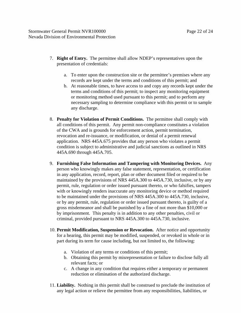
Stormwater General Permit NVR100000 Page 22 of 24 Nevada Division of Environmental Protection
7. Right of Entry. The permittee shall allow NDEP’s representatives upon the presentation of credentials:
a. To enter upon the construction site or the permittee’s premises where any
records are kept under the terms and conditions of this permit; and b. At reasonable times, to have access to and copy any records kept under the
terms and conditions of this permit; to inspect any monitoring equipment or monitoring method used pursuant to this permit; and to perform any necessary sampling to determine compliance with this permit or to sample any discharge.
8. Penalty for Violation of Permit Conditions. The permittee shall comply with
all conditions of this permit. Any permit non-compliance constitutes a violation of the CWA and is grounds for enforcement action, permit termination, revocation and re-issuance, or modification, or denial of a permit renewal application. NRS 445A.675 provides that any person who violates a permit condition is subject to administrative and judicial sanctions as outlined in NRS 445A.690 through 445A.705.
9. Furnishing False Information and Tampering with Monitoring Devices. Any
person who knowingly makes any false statement, representation, or certification in any application, record, report, plan or other document filed or required to be maintained by the provisions of NRS 445A.300 to 445A.730, inclusive, or by any permit, rule, regulation or order issued pursuant thereto, or who falsifies, tampers with or knowingly renders inaccurate any monitoring device or method required to be maintained under the provisions of NRS 445A.300 to 445A.730, inclusive, or by any permit, rule, regulation or order issued pursuant thereto, is guilty of a gross misdemeanor and shall be punished by a fine of not more than $10,000 or by imprisonment. This penalty is in addition to any other penalties, civil or criminal, provided pursuant to NRS 445A.300 to 445A.730, inclusive.
10. Permit Modification, Suspension or Revocation. After notice and opportunity
for a hearing, this permit may be modified, suspended, or revoked in whole or in part during its term for cause including, but not limited to, the following:
a. Violation of any terms or conditions of this permit; b. Obtaining this permit by misrepresentation or failure to disclose fully all
relevant facts; or c. A change in any condition that requires either a temporary or permanent
reduction or elimination of the authorized discharge.
11. Liability. Nothing in this permit shall be construed to preclude the institution of any legal action or relieve the permittee from any responsibilities, liabilities, or

Stormwater General Permit NVR100000 Page 23 of 24 Nevada Division of Environmental Protection
penalties established pursuant to any applicable Federal, State or local laws, regulations, or ordinances.
12. Property Rights. The issuance of this permit does not convey any property
rights, in either real or personal property, or any exclusive privileges, nor does it authorize any injury to private property or any invasion of personal rights, nor any infringement of Federal, State or local laws or regulations.
13. Severability. The provisions of this permit are severable, and if any provision of
this permit, or the application of any provisions of this permit to any circumstance, is held invalid, the application of such provision to other circumstances, and the remainder of this permit, shall not be affected thereby.

Stormwater General Permit NVR100000 Page 24 of 24 Nevada Division of Environmental Protection
Appendix A – Definitions Best management practices (``BMPs'') means schedules of activities, prohibitions of practices, maintenance procedures, and other management practices to prevent or reduce the pollution of ``Waters of the United States.'' BMPs also include treatment requirements, operating procedures, and practices to control plant site runoff, spillage or leaks, sludge or waste disposal, or drainage from raw material storage. Construction Activities - Construction activities include any clearing, grading and excavation activities that result in the disturbance of one (1) acre or more of total land area, or will disturb less than one (1) acre but are part of a larger common plan for development or sale that will ultimately disturb one (1) or more acres.. CWA - Clean Water Act (formerly referred to as the Federal Water Pollution Control Act or Federal Water Pollution Control Act Amendments of 1972) Public Law 92-500, as amended by Public Law 95-217, Public Law 95-576, Public Law 96-483 and Public Law 97-117, 33 U.S.C. 1251 et seq. CWA and regulations means the Clean Water Act (CWA) and applicable regulations promulgated thereunder. In the case of an approved State program, it includes State program requirements. Industrial Activities means temporary concrete, asphalt and material plants which are dedicated to the permitted construction activity. Large construction activity includes clearing, grading and excavation that results in the disturbance of five acres or more of total land area. Small construction activity includes the disturbance of less than one acre of total land area that is part of a larger common plan of development or sale if the larger common plan will ultimately disturb equal to or greater than one and less than five acres. Small construction activity does not include routine maintenance that is performed to maintain the original line and grade, hydraulic capacity, or original purpose of the facility. NDEP may waive the otherwise applicable requirements in a general permit for a storm water discharge from construction activities that disturb less than five acres where the value of the rainfall erosivity factor (``R'' in the Revised Universal Soil Loss Equation) is less than five during the period of construction activity. The rainfall erosivity factor is determined in accordance with Chapter 2 of Agriculture Handbook Number 703, Predicting Soil Erosion by Water: A Guide to Conservation Planning with the Revised Universal Soil Loss Equation (RUSLE), pages 21-64, dated January 1997. Stormwater means storm water runoff, snow melt runoff, and surface runoff and drainage.

Appendix BLocal Construction Program Checklists

THIS PAGE LEFT BLANK INTENTIONALLY

� ������������������� ��� ������ ����������������������� ������������
����������
�
������� ���������������� �
������ � �

THIS PAGE LEFT BLANK INTENTIONALLY

�
�
LAS VEGAS VALLEY STORMWATER QUALITY MANAGEMENT PROGRAM
CONSTRUCTION PERMIT SUBMITTAL CHECKLIST (Applies to all Grading, Site Development, Building, and Encroachment Permits and plans including Final, Parcel, Subdivision, Site Drainage and Erosion and Sediment Control Plans) Owner / Operator (applicant) Information Name:
Phone:
Address:
City: State: Zip Code:
Project Name:
Project Address/Location:
Signature: Date:
Total planned area of land disturbance = acres (should match grading permit application). If the area of land disturbance is one acre or more, the applicant must submit a copy of their Notice of Intent (NOI) to Nevada Division of Environmental Protection (NDEP) to be regulated under Stormwater General Permit NVR100000 and submit a copy of the receipt for payment of the annual fee or the letter of authorization from NDEP (address attached). Once payment has been received by NDEP, the applicant is immediately covered under the State’s permit.
1. Copy of NOI attached
2. Copy of receipt or letter of authorization from NDEP attached
By submitting a copy of the NOI and the receipt or authorization from NDEP, the applicant acknowledges that they are aware of the requirements set forth in the State’s General Permit and have developed and will implement a site specific Stormwater Pollution Prevention Plan (SWPPP). The applicant further acknowledges that they are aware of the Las Vegas Valley Construction Site BMP Guidance Manual and the required performance standards set forth in Section 3.2 of the manual. To ensure compliance with these performance standards, the applicant shall submit a completed Performance Standards Compliance Checklist, indicating the BMPs that implement standards 1 – 12. It is recommended that the applicant also attach a copy of the checklist to their SWPPP.

�
�
Copy of Performance Standards Compliance Checklist attached Yes No
Were calculations required for sizing of diversion channels and/or sediment retention basins? If the answer is yes, pursuant to NRS 625.565, a Nevada Registered Professional Engineer must review and stamp plans, such as grading plans and reports that require engineering calculations.
In addition to the submittal requirements specified above and in the ordinances, the following shall be included as a set of standard notes to be depicted on all site plans that disturb one acre or larger.
Standard notes from Section 3.5 of the Las Vegas Valley Construction Site BMP Guidance Manual on design plans
�������������� ������ ��������������
Nevada Division of Environmental Protection Bureau of Water Pollution Control 901 South Stewart Street Suite 4001 Carson City, NV 89701-5249 Phone: (775) 687-9429 Fax: (775) 687-4684 Web: http://ndep.nv.gov/bwpc/index.htm

�
�
LAS VEGAS VALLEY STORMWATER QUALITY MANAGEMENT PROGRAM �
PERFORMANCE STANDARDS COMPLIANCE CHECKLIST �
� Owner / Operator (applicant) and Project Information
Name: Phone:
Address:
City: State: Zip Code:
Project Name:
Project Address/Location:
Signature: Date: �
�
� � � ��� �� � � �� �� � � �
�� � � ����� � �� �� �
�� � � � �
��� � � � �� �
��� � � � � �� � � � ��� ��� �� �� � �� �� � � �� � �� � �� �� �� � � �
� � � ���� ��� �� � � �� � �
� � � ���� � � � �� � � �
� � � ���� � � � � ��� � ��� ��� � �
� � � ��� � ! � � ���" � � � � � �
� #����� �� �� ��� �� �� �� � � �� �$ � � � �� ��� �� ��� � ��� ��� �% �� � �
�
� & �� � �� �
� ' (% � �
��� � �� ) ���� � � �� �� �) � �� �� � � �
� #����#�� � �� ��� ��� ��� � �� � �
� #������ � � � � � � �
� #��*�� � � ���� ��� �� �
� #������ � ��� � �" � � � � � � � � �
� � � ��+�" � , � � � �� ��� � �
� & �� � �� �
� ' (% � �
��� � �� �� ��� �� ! � � � � #��-�� �, � �� �� �� �� � � � �
� #����� �! � �� �� ! � �� �� � � � �
� #������ � ��� � �" � � � � � � � � �
� #��*�� � � ���� ��� �� �
� #����#�� � �� ��� ��� ��� � �� � �
� � � ��+�" � , � � � �� ��� � �
� � � ����& �� � � �. ���� ��� � ���� �� � �
� � � ����� � �� � � �� � ���� �� �
� � � ����/ �� , � ��. ���� ��� � �� � � �
� & �� � �� �
� ' (% � �
��� � � � �� � � , � 0 � � ��� �� � �� �� � �, � �, � �� ���� � �
� #��-�� �, � �� �� �� �� � � � �
� � � ������ � � �� � � � � �
� #�����& � ��� ��� �� �� ��� � �
� & �� � �� �
� ' (% � �
The checklist that follows identifies the BMPs that can be used at construction sites to meet each of the Performance Standards of the Las Vegas Valley Construction Site BMP Guidance Manual (BMP Guidance Manual). You must select at least one BMP for each performance standard to meet the minimum requirements. Please refer to the BMP Guidance Manual to assist you in selecting BMPs for your site. It is the responsibility of the person who fills out this checklist to ensure that the BMPs selected are included in the contract bid documents and implemented at the site. If your project or site has characteristics that make meeting a performance standard infeasible or inapplicable (e.g. size of site, slope of site), please explain these characteristics at the bottom of the form.

�
�
� � � ��� �� � � �� �� � � �
�� � � ����� � �� �� �
�� � � � �
��� � � � �� �
1�� � �� �� ��2 � �� �2 � 0 � 3� � �� �� �� �� � � � � � �� �� �� �� � �� � � �
� � � ���� ��� �� � � �� � �
� #��-�� �, � �� �� �� �� � � � �
� #����� �� �� ��� �� �� �� � � �� �$ � � � �� ��� � �
� � � ����& �� � � �. ���� ��� � ���� �� � �
� � � ����� � �� � � �� � ���� �� � �
� � � ����/ �� , � ��. ���� ��� � �� � � �
� � � ��1�� ����. � � � �
� � � ��4� � � ! � �� �0 �� ��� � � ���� � � � � � �
� #�����& � ��� ��� �� �� ��� � �
� � � ��*�� �� �� �� �� � �5 �� ��� �� �� ��� � �
� & �� � �� �
� ' (% � �
+�� 5 � �� ���� � �� � ����� ! � �� ��� �� � �� � �� � �� � � � � �) 0 �� �� � �� �� �� ��� �
� � � ������ � � �� � � � � �
� � � ����& �� � � �. ���� ��� � ���� �� �
� � � ����� � �� � � �� � ���� �� �
� � � ����/ �� , � ��. ���� ��� � �� � �
� � � ��1�� ����. � � � �
� � � ��-� � � ! � �� �0 �� � �� � �� �� ! � � �
� � � ��4� � � ! � �� �0 �� � �� � ��� � � � � � �
� & �� � �� �
� ' (% � �
*�� " � � � , � �� � � � �� �� �� � �� � ��
� 6 � � �� �� � � �' � �� �' � 7�1��� � �� �� ��& ' � " 6 � 5& ' �� #" � 5 �� 6 � � 5 % � ��8 #�9 � 5� :�
�
� & �� � �� �
� ' (% � �
4�� �� ��� ��� ��� �� ��� � � �� �� ; ��� �
� #��1�� �� ) ���� � ��� � ��� ��� �# ��� � � �
� #��+��� � ��� ��� �" � � �� �� ) ���� � ��� � �
� � � ������� � ��� ��� �# ��� � (#; ��� ��� �< � � � �
�
� / 8 �+�" � � �� 2 � � ! � � ( �� � � � ����� � � � � �
� & �� � �� �
� ' (% � �
-�� � � � � � �� � �� ��� �� �� �2 � � �� � �
� / 8 ���� � �� �< � � �� �� � � � � � � �� �
� / 8 �1�� ! ������ �� � � � ��� �� � �
� & �� � �� �
� ' (% � �
�= �� � � � � � �� > � �! � � ��� �, � � � �� � �
� / 8 ���#> � �! � � ��� � � �� � � �� �� � � �� � � �
� / 8 ���� � � �� � �� �< � � � � 2 �% �� � � �
� & �� � �� �
� ' (% � �
���� � �� ) ���� � ��� �� ��� � ��, � � �� �� �) � �� �� � � �
� � � ��� � ! � � ���" � � � � � �
� #����� � � � � � � �
� #��*�� � � ���� ��� �� �
� � � ��+�" � , � � � �� ��� � �
� & �� � �� �
� ' (% � �
Explanation why performance standard(s) cannot be met:

LAS VEGAS VALLEY STORMWATER QUALITY MANAGEMENT PROGRAM
CONSTRUCTION SITE INSPECTION CHECKLIST The contractor or other responsible party shall inspect the site at a minimum weekly and within 24 hours after a storm event of 0.5 inches or greater. The owner/operator may use their own construction site inspection checklist, however, it must contain, at a minimum, the information required by this checklist. Inspection checklists shall be maintained onsite for review by State and local government inspectors. Project Name and File Number: Project Location: Date: Inspected by:
(Name and Company) Type of Inspection: Yes No N/A
1. Is there evidence of pollutant discharge from the property?
2. Are roadways, storm drains, watercourses or swales or channels leading offsite free of sedimentation, litter, wastes and hazardous materials?
3. Are all material and equipment storage and maintenance areas reasonably clean and free of spills, leaks or other sources of potentially polluting materials?
4. Are materials and waste managed adequately to minimize potential to impact the environment?
5. Are all the necessary BMPs installed, functioning properly, and adequately maintained
If you answered YES to Question 1 or NO to Questions 2-5, describe any corrective actions that must be taken to remedy the problem and when the corrective action is to be taken. Attach additional sheets as needed.
Checklist Item Corrective Action Needed Date to be Completed
Routine Post-Storm Other

THIS PAGE LEFT BLANK INTENTIONALLY

Appendix CConstruction Site BMPs

THIS PAGE LEFT BLANK INTENTIONALLY

Las Vegas Valley Construction Site BMP Guidance Manual January 2009
APPENDIX C
CONSTRUCTION SITE BEST MANAGEMENT PRACTICES

THIS PAGE LEFT BLANK INTENTIONALLY
Construction Site Best Management Practices
Las Vegas Valley Construction Site BMP Guidance Manual Page i Revision 1, December 2008
Table of Contents PL PLANNING .................................................................................... C-1 PL-1 Site Design ................................................................................................................ C-2 PL-2 Scheduling ................................................................................................................ C-5 PL-3 Phased Construction ............................................................................................... C-8 PL-4 Topsoil Reuse .......................................................................................................... C-10 PL-5 Employee Training .................................................................................................. C-13 EC EROSION CONTROL ..................................................................... C-15 EC-1 Erosion Control Mats ............................................................................................. C-16 EC-2 Mulching ................................................................................................................... C-24 EC-3 Protection of Trees and Vegetation in Construction Areas .............................. C-31 EC-4 Pipe Slope Drains .................................................................................................... C-36 EC-5 Stabilized Construction Entrance ......................................................................... C-43 EC-6 Construction Road Stabilization ........................................................................... C-48 EC-7 Dust Control ............................................................................................................ C-53 EC-8 Temporary Access Waterway Crossing ................................................................ C-61 EC-9 Diversion Dikes ....................................................................................................... C-67 EC-10 Drainage Swales ....................................................................................................... C-73 EC-11 Outlet Protection, Velocity Dissipation Devices ................................................ C-79 EC-12 Surface Roughening ................................................................................................ C-84 SPC SEDIMENT AND POLLUTANT CONTROL ................................... C-90
SPC-1 Organic Filter Barrier .............................................................................................. C-91 SPC-2 Sand Bag Barrier ...................................................................................................... C-97 SPC-3 Gravel Filter Berms ................................................................................................. C-103 SPC-4 Check Dams ............................................................................................................. C-109 SPC-5 Silt Fence .................................................................................................................. C-115 SPC-6 Revegetation and Landscaped Buffers ................................................................. C-122 SPC-7 Storm Drain Inlet Protection ................................................................................ C-127 SPC-8 Temporary Sediment Basins .................................................................................. C-134 SPC-9 Temporary Sediment Traps ................................................................................... C-140 SPC-10 Sediment Dewatering Operations ......................................................................... C-147 SPC-11 Construction Entrance/Exit Tire Wash .............................................................. C-151 GH GENERAL HOUSEKEEPING ......................................................... C-156
GH-1 Chemical Management ........................................................................................... C-157 GH-2 Solid Waste Management ....................................................................................... C-162 GH-3 Equipment Maintenance Procedures ................................................................... C-167 GH-4 Designated Washdown Areas ................................................................................ C-171 GH-5 Spill Containment Plan ........................................................................................... C-176 GH-6 Road Sweeping/Trackout Cleaning ...................................................................... C-181

THIS PAGE LEFT BLANK INTENTIONALLY
Construction Site Best Management Practices
Las Vegas Valley Construction Site BMP Guidance Manual Page C-1 January 2009
PL Planning This section presents the planning concepts that can be incorporated into construction sites to provide temporary and permanent erosion and sediment controls as well as long-term water quality benefits.
• PL-1 Site Design • PL-2 Scheduling • PL-3 Phased Construction • PL-4 Topsoil Reuse • PL-5 Employee Training

Construction Site Best Management Practices
Page C-2 Las Vegas Valley Construction Site BMP Guidance Manual January 2009
Site Design
Definition
The incorporation of site design features in the planning process that will help reduce sediment pollution and minimize the need for additional sediment control BMPs.
RATINGS Associated Costs H M L
Implementation
Maintenance
Training
Target Pollutants Removal H M L
Oil and Grease
Nutrients
Sediment
Floatable Material
Metals
Other Construction Waste
GENERAL INFORMATION FIGURES Applicability – Effectiveness: • All Construction Projects– high Most effective when used with: • All Applicable BMPs Alternative BMPs: • None
Photos/Sketches:• PL-1 Active Construction Site Sketch CAD Drawings: • None
Purpose
To implement design features in the planning process that can significantly help to minimize the need for additional sediment controls. Some of these design features can also be used to control and enhance the quality of stormwater runoff during constuction as well as provide post-construction structural conrols.
Appropriate Applications
Site Design considerations can be used on all constuction projects.
Limitations
• Site constraints may limit the ability to use existing vegetation as a filter strip.
PL-1

Construction Site Best Management Practices
Las Vegas Valley Construction Site BMP Guidance Manual Page C-3 January 2009
• Grass lined swales are difficult to establish in the Las Vegas Valley unless they have a permanent irrigation system.
Recommended Standards and Specifications
• Limit the amount of continuously connected disturbed soil areas.
• Provide active construction areas with base grade elevations below the elevation of the surrounding area. An active construction area located below the grade of surrounding pavement and sidewalks may be considered to have effective perimeter controls since the entire work area would effectively function as a detention basin during storm events. An example is provided in the graphic below where below grade construction activities and existing curb and gutter result in effective perimeter control.
• Provide additional perimeter control using vegetated filter strips in conjunction with other controls such as fiber rolls or silt fences. Vegetated filter strips can also provide permanent post construction structural controls and can consist of preserved existing vegetated areas.
• Limit flow velocities and trap sediments using grass lined swales. If these features are located downstream of the site and are constructed prior to the majority of other construction activities, they can also provide permanent post construction structural controls.
Recommended Maintenance and Inspection
• Inspect site design features weekly during construction activities that are intended to block or filter stormwater runoff to ensure they are adequate to prevent sediment transport off-site. If they are not, additional BMPs should be installed.
References
Truckee Meadows, Construction Site Best Management Practices Handbook, February 2003

Construction Site Best Management Practices
Page C-4 Las Vegas Valley Construction Site BMP Guidance Manual January 2009
PL-1 Active Construction Site Sketch
Below Grade Construction Site Sketch (Courtesy Truckee Meadows).

Construction Site Best Management Practices
Las Vegas Valley Construction Site BMP Guidance Manual Page C-5 January 2009
Scheduling
Definition
Scheduling is the development of a written plan that includes sequencing of construction activities and the implementation of BMPs such as erosion control and sediment control while taking local climate (rainfall, wind, etc.) into consideration.
RATINGS Associated Costs H M L
Implementation
Maintenance
Training
Target Pollutants Removal H M L
Oil and Grease
Nutrients
Sediment
Floatable Material
Metals
Other Construction Waste
GENERAL INFORMATION FIGURES Applicability – Effectiveness: • All Construction Projects that Include Grading or
Earthwork– high Most effective when used with: • All Applicable BMPs Alternative BMPs: • None
Photos/Sketches:• None CAD Drawings: • None
Purpose
The purpose is to reduce the amount and duration of soil exposed to erosion by wind, rain, runoff, and vehicle tracking, and to perform the construction activities and control practices in accordance with the planned schedule.
Appropriate Applications
Proper sequencing of construction activities to reduce erosion potential should be incorporated into the schedule of every construction project. Use of other, more costly yet less effective, erosion and sediment control BMPs may often be reduced through proper construction sequencing.
PL-2

Construction Site Best Management Practices
Page C-6 Las Vegas Valley Construction Site BMP Guidance Manual January 2009
Limitations
Environmental constraints such as nesting season prohibitions reduce the full capabilities of this BMP.
Recommended Standards and Specifications
• Avoid intense rainy periods. Schedule major grading operations to minimize disturbance during months in which intense thunderstorms are common (July and August), when practical. Allow enough time before the summer thunderstorm season begins to stabilize the soil with vegetation or physical means or to install sediment trapping devices.
• Plan the project and develop a schedule showing each phase of construction. Clearly show how the summer thunderstorm season relates to soil disturbing and re-stabilization activities. Incorporate the construction schedule into the SWPPP.
• Include on the schedule, details on the thunderstorm season implementation and deployment of:
• Erosion control BMPs • Sediment control BMPs • Tracking control BMPs • Wind erosion control BMPs • Non-stormwater BMPs • Waste management and materials pollution control BMPs
• Include dates for activities that may require non-stormwater discharges such as dewatering, sawcutting, grinding, drilling, boring, crushing, blasting, painting, hydro-demolition, mortar mixing, pavement cleaning, etc.
• Work out the sequencing and timetable for the start and completion of each item such as site clearing and grubbing, grading, excavation, paving, foundation pouring utilities installation, etc., to minimize the active construction area during the rainy season.
• Sequence trenching activities so that most open portions are closed before new trenching begins.
• Incorporate staged seeding and re-vegetation of graded slopes as work progresses.
• Schedule establishment of permanent vegetation during appropriate planting time for specified vegetation.
• Non-active areas should be stabilized as soon as practical after the cessation of soil disturbing activities or one day prior to the onset of precipitation.
• Monitor the weather forecast for rainfall.

Construction Site Best Management Practices
Las Vegas Valley Construction Site BMP Guidance Manual Page C-7 January 2009
• When rainfall is predicted, adjust the construction schedule to allow the implementation of soil stabilization and sediment treatment controls on all disturbed areas prior to the onset of rain.
• Be prepared year round to deploy erosion control and sediment control BMPs. Erosion may be caused during dry seasons by un-seasonal rainfall, wind, and vehicle tracking. Keep the site stabilized year round, and retain and maintain sediment trapping devices in operational condition.
• Apply permanent erosion control to areas deemed substantially complete during the project’s defined seeding window.
Recommended Maintenance and Inspection
• Verify that work is progressing in accordance with the schedule. If progress deviates, take corrective actions.
• Amend the schedule when changes are warranted.
• Amend the schedule prior to the summer thunderstorm season to show updated information on the deployment and implementation of construction site BMPs.
References
CALTRANS, State of California Department of Transportation, Construction Site Best Management Practices (BMPs) Manual, March 2003.
http://www.dot.ca.gov/hq/construc/stormwater/manuals.htm Truckee Meadows, Construction Site Best Management Practices Handbook, February 2003

Construction Site Best Management Practices
Page C-8 Las Vegas Valley Construction Site BMP Guidance Manual January 2009
Phased Construction
Definition The sequencing of land disturbance on large construction projects.
RATINGS Associated Costs H M L
Implementation
Maintenance
Training
Target Pollutants Removal H M L
Oil and Grease
Nutrients
Sediment
Floatable Material
Metals
Other Construction Waste
GENERAL INFORMATION FIGURES Applicability – Effectiveness: • Large Construction Projects– high Most effective when used with: • All Applicable BMPs Alternative BMPs: • None
Photos/Sketches:• None CAD Drawings: • None
Purpose
To reduce on-site erosion and sediment transport off-site by sequencing land disturbance and erosion and sediment control measures.
Appropriate Applications
Locations where water quality might be impacted by erosion from earthwork.
Limitations
Weather and other unforeseen conditions that may affect construction phasing.
PL-3

Construction Site Best Management Practices
Las Vegas Valley Construction Site BMP Guidance Manual Page C-9 January 2009
Recommended Standards and Specifications
Construction phasing schedules should include at a minimum the following:
• A schedule for the installation of erosion and sediment controls. • A schedule that is compatible with the general construction schedule.
The following is an example of construction site sequencing:
1. Construction Access Stabilize bare ground as soon as construction begins.
2. Sediment Traps and Barriers Barriers should be installed and added prior to grading.
3. Runoff Control Install diversion channels and dikes before the onset of grading activities.
4. Erosion Control Disturbed stream banks should be stabilized as soon as possible.
5. Land Clearing and Grading Clear and grade the site after sediment and runoff control measures have been installed.
6. Maintenance Conduct frequent inspections and remove accumulated sediments from the BMPs.
7. Surface Stabilization Apply immediately to any disturbed areas to control dust and erosion.
8. Building Construction Install needed erosion and sediment control devices.
9. Maintenance Conduct frequent inspections and remove accumulated sediments from the BMPs
10. Landscaping and Final Stabilization Stabilize the area and remove all temporary sediment control and construction wastes.
Recommended Maintenance and Inspection
• Verify frequently that work is on schedule according to the project plan.
• Revise the plan before construction activities are implemented when changes to the project schedule are unavoidable.
• Communicate significant schedule changes to city/county staff to assist with inspection efforts.
References
Truckee Meadows Construction Site Best Management Practices Handbook, February 2003

Construction Site Best Management Practices
Page C-10 Las Vegas Valley Construction Site BMP Guidance Manual January 2009
Topsoil Reuse
Definition The salvaging, stockpiling, and reapplication of native topsoil and other selected materials for reuse during revegetation activities.
RATINGS Associated Costs H M L
Implementation
Maintenance
Training
Target Pollutants Removal H M L
Oil and Grease
Nutrients
Sediment
Floatable Material Metals Other Construction Waste
GENERAL INFORMATION FIGURES Applicability – Effectiveness: • Projects where revegetation is desirable.– high Most effective when used with: • All Applicable BMPs Alternative BMPs: • None
Photos/Sketches:• None CAD Drawings: • None
Purpose
To encourage the salvaging, stockpiling and reapplication of native topsoil and other selected materials for reuse during revegetation activities. Reuse of native topsoil can be a critical factor to the success of revegetation efforts, particularly when attempting to reestablish native vegetation.
Appropriate Applications
• Sites where revegetation with native plant species is desirable.
• Particularly applicable on floodplains, wetlands, streambanks, and sensitive habitat areas.
• Proper topsoil management can result in successful revegetation, enhanced productivity, reduced erosion, and permanent stabilization.
PL-4

Construction Site Best Management Practices
Las Vegas Valley Construction Site BMP Guidance Manual Page C-11 January 2009
Limitations
• Requires advanced planning prior to grading and earthwork activities.
• Stockpiles may constrict the area available for construction activity.
• Stockpile runoff can negatively impact water quality.
Recommended Standards and Specifications
• Conduct a soil survey as part of pre-project site assessment to identify the location, depth and amount of soils suitable for salvaging.
• Excavate topsoil carefully, avoid large rocks, and stockpile material where it will not be contaminated by demolition or construction activities.
• Screen topsoil to remove large rocks, roots and vegetation when necessary to establish a representative native growth medium.
• If there is sufficient turf in good condition on site, it can be machine cut and stockpiled for reuse.
• Where suitable, strip groundcover and shrubs for reuse after construction.
• Shrubs can be carefully removed and stored with their roots covered with mulch or loose soil.
• Soil stockpiles must be covered or protected with temporary stabilization measures such as mulch or temporary vegetation.
• Temporary stabilization must be established no later than 21 days after stockpiles are created.
• Perimeter controls such as sandbag barriers must be installed as soon as practicable and must be in place prior to the onset of precipitation.
The following elements should be considered when developing a topsoil management plan:
• The amount and quality of existing topsoil.
• The area that topsoil will be reused and the required depth of application.
• Methodology for salvaging topsoil.
• Stockpile location, duration of storage and protection against erosion and sediment transport.
• Availability of additional amendments to supplement topsoil reclamation.

Construction Site Best Management Practices
Page C-12 Las Vegas Valley Construction Site BMP Guidance Manual January 2009
Recommended Maintenance and Inspection
• Inspect covers and perimeter controls weekly.
• Replace or repair covers or augment temporary stabilization measures as needed.
• Replace or repair perimeter controls as needed.
References
Truckee Meadows, Construction Site Best Management Practices Handbook, February 2003
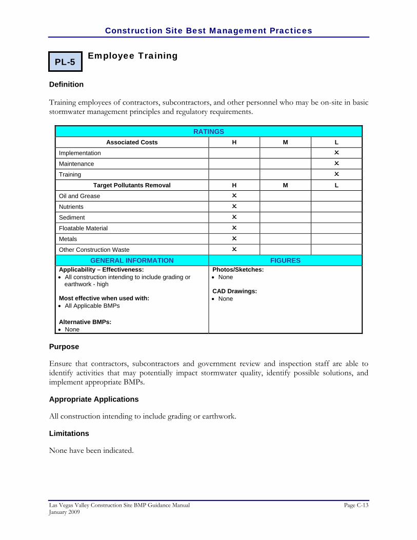
Construction Site Best Management Practices
Las Vegas Valley Construction Site BMP Guidance Manual Page C-13 January 2009
Employee Training
Definition Training employees of contractors, subcontractors, and other personnel who may be on-site in basic stormwater management principles and regulatory requirements.
RATINGS Associated Costs H M L
Implementation
Maintenance
Training
Target Pollutants Removal H M L
Oil and Grease
Nutrients
Sediment
Floatable Material
Metals
Other Construction Waste
GENERAL INFORMATION FIGURES Applicability – Effectiveness: • All construction intending to include grading or
earthwork - high Most effective when used with: • All Applicable BMPs Alternative BMPs: • None
Photos/Sketches:• None CAD Drawings: • None
Purpose
Ensure that contractors, subcontractors and government review and inspection staff are able to identify activities that may potentially impact stormwater quality, identify possible solutions, and implement appropriate BMPs.
Appropriate Applications
All construction intending to include grading or earthwork.
Limitations
None have been indicated.
PL-5
Construction Site Best Management Practices
Page C-14 Las Vegas Valley Construction Site BMP Guidance Manual January 2009
Recommended Standards and Specifications
• Incorporate stormwater quality management training with existing construction related training programs.
• Provide refresher courses or training classes on a regular basis.
• Include standard operating procedures and training in spill prevention and response.
• Train personnel in the proper use, storage, and disposal of pesticides and other construction related chemicals.
• Inform off-site contractors of on-site procedures.
• Conduct “tailgate” training sessions at project sites prior to the start of construction activities.
• A formal training course should include information about the following:
• Environmental concerns about runoff from construction sites • The Clean Water Act and the NPDES program • NDEP’s General Permit and local policies and procedures • Principles of erosion and sediment control • Best Management Practices and appropriate applications • Proper design and installation procedures • Inspection, maintenance, and reporting requirements
References
Truckee Meadows, Construction Site Best Management Practices Handbook, February 2003

Construction Site Best Management Practices
Las Vegas Valley Construction Site BMP Guidance Manual Page C-15 January 2009
EC Erosion Control Erosion control refers to methods for reducing the volume or velocity of stormwater runoff, which will come into contact with exposed areas of the project site. Erosion control methods involve limiting the exposure of graded areas to off-site runoff through modifications of the construction design plan or scheduling, reducing runoff velocities, providing vegetative cover, installing structural controls, and implementing other on-site management options. If a pre–manufactured product is to be implemented on a site for erosion control, the contractor should always follow the manufacturer’s installation and maintenance recommendations as the primary reference for implementation.
• EC–1 Erosion Control Mats • EC–2 Mulching • EC–3 Protection of Trees and Vegetation in Construction Areas • EC–4 Pipe Slope Drains • EC–5 Stabilized Construction Entrance • EC–6 Construction Road Stabilization • EC–7 Dust Control • EC–8 Temporary Access Waterway Crossing • EC–9 Diversion Dikes • EC–10 Drainage Swales • EC–11 Outlet Protection, Velocity Dissipation Devices • EC–12 Surface Roughening

Construction Site Best Management Practices
Page C-16 Las Vegas Valley Construction Site BMP Guidance Manual January 2009
Erosion Control Mats
Definition
Geotextiles, mats, plastic covers, or erosion control blankets designed to stabilize disturbed soil areas and protect soils from erosion by wind or water.
RATINGS Associated Costs H M L
Implementation
Maintenance
Training
Target Pollutants Removal H M L
Oil and Grease
Nutrients
Sediment
Floatable Material
Metals
Other Construction Waste
GENERAL INFORMATION FIGURES Applicability – Effectiveness: • Slope Protection – moderate Material Stockpiles – Moderate: • Most effective when used with: Seeding or other
re–vegetation methods described in SPC–6 Revegetation
Alternative BMPs: • Consider using chemical stabilization for large
areas or steeper slopes: EC–7 Dust Control
Photos/Sketches:• EC–1 Erosion Control Mats Photos CAD Drawings: • Installation of Netting and Matting • Orientation of Netting and Matting
Purpose
Erosion control matting is used to reduce rainfall impact, hold soil in place, and absorb and hold moisture near the soil surface. The matting may be used alone or with a mulch during the establishment of protective vegetative cover on critical slopes.
Appropriate Applications
Erosion control matting can be applied to:
• Steep slopes, generally steeper than 1:3 (V:H). • Slopes with newly vegetated slopes or where the erosion potential is high. • Slopes and disturbed soils where mulch must be anchored. • Disturbed areas where plants are slow to develop.
EC-1 ECM
ECM

Construction Site Best Management Practices
Las Vegas Valley Construction Site BMP Guidance Manual Page C-17 January 2009
• Channels with flow velocities exceeding 3 to 7 feet per second (ft/sec) • Stockpiles. • Slopes adjacent to water bodies.
Limitations
Geotextiles, mats, plastic covers, and erosion control covers have maximum flow rate limitations; consult the manufacturer for proper selection.
• Blankets and mats:
• More expensive than other erosion control measures, due to labor and material costs. This usually limits their application to areas inaccessible to hydraulic equipment, or where other measures are not applicable, such as channels.
• Generally not suitable for excessively rocky sites, or areas where the final vegetation will be mowed (since staples and netting can catch in mowers).
• Plastic sheeting:
• Easily vandalized, easily torn, photodegradable, and must be disposed of at a landfill.
• Plastic results in 100 percent runoff, which may cause serious erosion problems in the areas receiving the increased flow.
• Limit the use of plastic covers to covering stockpiles, or very small graded areas for short periods of time (such as through one imminent storm event), until alternative measures, such as seeding and mulching, may be installed.
Planning Considerations
Consider using Revegetation in conjunction with Erosion Control Mats for additional erosion control and stabilization.
Recommended Standards and Specifications
• Jute Mat – should be a uniform plain weave of undyed and unbleached single jute yarn and weigh about 1.2 pounds per linear yard of cloth. The yarn should be loosely twisted, with an average twist of not less than 1.6 turns per inch, and should not vary in thickness by more than half its normal diameter.
• Straw Mat – should be a machine produced mat consisting of about 70 ± 3 percent agricultural straw and 30 ± 3 percent coconut fiber. The blanket should be of consistent thickness with the straw and coconut fiber evenly distributed. The blanket should be covered on the top side with polypropylene netting having an approximate b" × b" mesh containing ultraviolet additives to resist breakdown, and on the bottom, have a polypropylene netting with an approximate ½" × ½" mesh.

Construction Site Best Management Practices
Page C-18 Las Vegas Valley Construction Site BMP Guidance Manual January 2009
• Excelsior Mat – should be wood excelsior, about 48 inches in width, and about 0.8 pounds per square yard. The excelsior material should be covered with a netting to facilitate handling and to increase strength.
• Glass Fiber Matting – should be made of bonded textile glass fibers with an average fiber diameter of eight to twelve microns and two to four inch strands of fiber bonded with phenol formaldehyde resin. Mat should be roll type, water permeable, minimum thickness ¼ inch, maximum thickness ½ inch, and have a density greater than three pounds per cubic foot.
• Other Mulch Nettings – such as paper, plastic, cotton or fiber glass matting should be installed according to the manufacturer's recommendations.
• Staples – used as anchors should be Number 11 gauge wire or heavier, and the length should be six to ten inches, minimum.
Installation
• Site Preparation: After the site has been shaped and graded to the approved design, prepare a friable seed bed, relatively free from clods and rocks more than 1.5 inches in diameter and any foreign material that will prevent contact of the protective mat with the soil surface.
• Planting: Fertilize and seed in accordance with seeding or other type of planting plan. When using jute matting on a seeded area, apply approximately half the seed before laying the mat and the remainder after laying the mat. The protective matting can be laid over sprigged areas when grass has been planted. Where vines or other ground covers are to be planted, lay the protective matting first and then plant through matting.
• Erosion Stops: Erosion stops are made of glass fiber strips, excelsior matting strips or tight–folded jute and are useful on steep, highly erodible slopes. They prevent water from flowing below the erosion control matting at the matting joints. Erosion stops can be placed in narrow trenches six to twelve inches deep across the channel, left flush with the soil surface, and must extend the entire cross section of designed flow. Straw wattles (see Organic Filter Barrier) are commonly installed as erosion stops
• Laying and Securing Matting: Before laying the matting, all erosion stops should be installed and the friable seed bed made free of clods, rocks, and roots. Most matting comes with manufacturer's recommendations for installation, which should always be followed. The matting should be unrolled starting at the upper end of the channel, allowing a four–inch overlap of mattings along the center of channel. To secure, bury the top ends of matting in a narrow trench, minimum of six inch depth. Backfill trench and tamp firmly to conform to channel cross section. Secure with a row of staples about four inches down slope from trench with staples twelve inches apart.
Construction Site Best Management Practices
Las Vegas Valley Construction Site BMP Guidance Manual Page C-19 January 2009
• Where matting crosses erosion stops, reinforce with a double row of staples, six–inch spacing, staggered pattern on either side of erosion stop. Likewise, overlaps joining the length of matting together and the discharge end of the matting liner should be similarly secured with a double row of staples.
• Mechanical or manual laydown equipment should be capable of handling full rolls of fabric, and laying the fabric smoothly, without wrinkles or folds. The equipment should be in accordance with the fabric manufacturer's recommendations or as approved by the Engineer.
• The surface upon which the separation fabric will be placed should be compacted and finished according to the manufacturer's recommendations.
• Final Check: Make sure matting is uniformly in contact with the soil.
• All lap joints are secure. • All staples are flush with the ground. • All disturbed areas seeded.
Recommended Maintenance and Inspection
• Inspect blankets and mats periodically after installation. Installation should be inspected after significant rainstorms to check for erosion and undermining. If washout or breakage occurs, re–install the material after repairing the damage to the slope or channel.
• Repairs may include re–anchoring loosened nettings and replace lost net and staples as required.
• Reapply or replace temporary soil stabilization when protected area becomes exposed or exhibits visible erosion.
Post Construction Methods
None.
References
CALTRANS, State of California Department of Transportation, Construction Site Best Management Practices (BMPs) Manual, March 2003. http://www.dot.ca.gov/hq/construc/stormwater/manuals.htm
Kamber Engineering, Gaithersburg, Maryland, Sedimentation and Erosion Control, An Inventory of Current
Practices, USEPA, April, 1991. North Central Texas Council of Governments, Integrated Storm Water Management (iSWM) Design
Manual for Construction, December 2003.

Construction Site Best Management Practices
Page C-20 Las Vegas Valley Construction Site BMP Guidance Manual January 2009
Tacoma Public Works Environmental Services, City of Tacoma Surface Water Management Manual Volume II, Construction Stormwater Pollution Prevention, January 1993.
http://www.ci.tacoma.wa.us/waterservices/permits/Manual.htm U. S. Environmental Protection Agency, Construction Site Storm Water Runoff Control, National Menu of
Best Management Practices for Storm Water Phase II, December 1999. http://cfpub2.epa.gov/npdes/stormwater/menuofbmps/con_site.cfm

Construction Site Best Management Practices
Las Vegas Valley Construction Site BMP Guidance Manual Page C-21 January 2009
EC–1 Erosion Control Mats Photos/Sketches
Schematic of applying erosion control to a slope (Courtesy of CALTRANS)
Biodegradable erosion control (Courtesy of EPA)
Applying sod to a slope (Courtesy of Douglas County)

Construction Site Best Management Practices
Page C-22 Las Vegas Valley Construction Site BMP Guidance Manual January 2009
EC-1 Erosion Control Mats Drawings
(Courtesy of Maricopa County)

Construction Site Best Management Practices
Las Vegas Valley Construction Site BMP Guidance Manual Page C-23 January 2009
(Courtesy of Maricopa County)
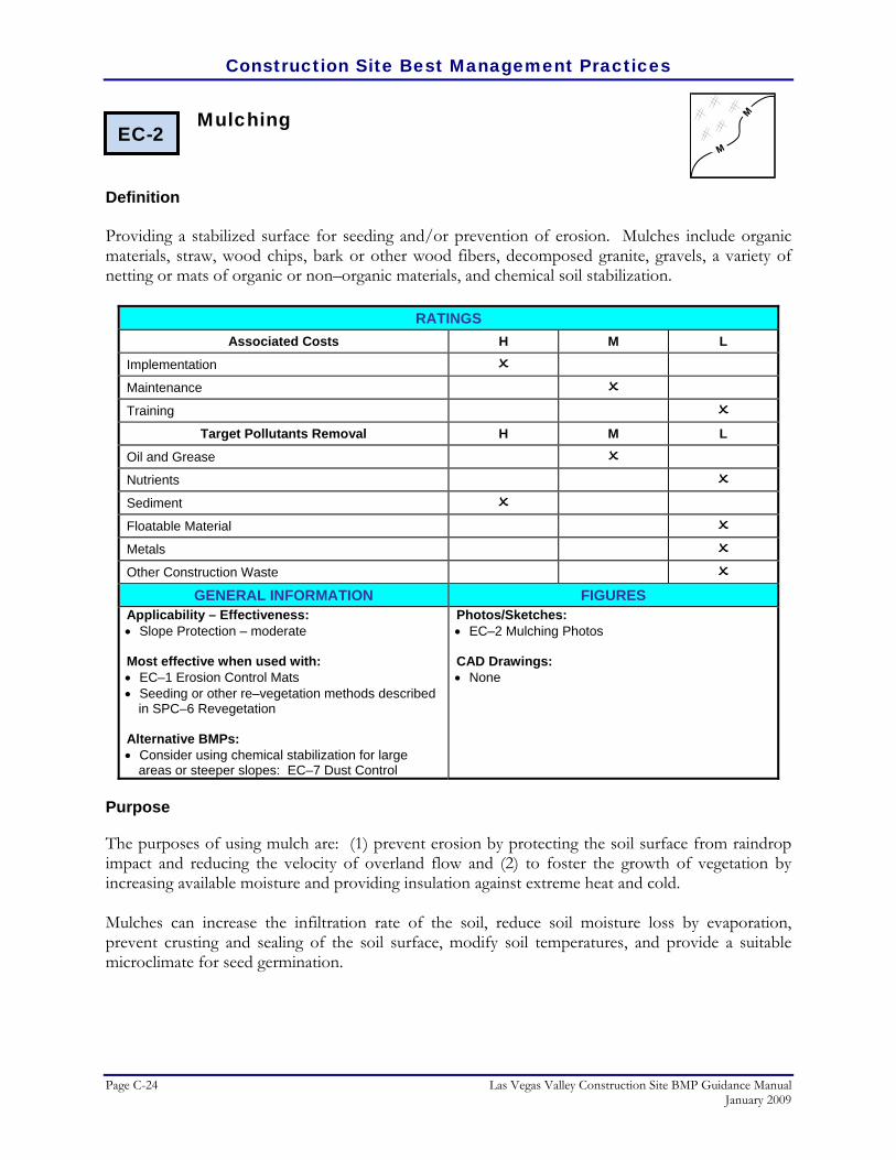
Construction Site Best Management Practices
Page C-24 Las Vegas Valley Construction Site BMP Guidance Manual January 2009
Mulching
Definition Providing a stabilized surface for seeding and/or prevention of erosion. Mulches include organic materials, straw, wood chips, bark or other wood fibers, decomposed granite, gravels, a variety of netting or mats of organic or non–organic materials, and chemical soil stabilization.
RATINGS Associated Costs H M L
Implementation
Maintenance
Training
Target Pollutants Removal H M L
Oil and Grease
Nutrients
Sediment
Floatable Material
Metals
Other Construction Waste
GENERAL INFORMATION FIGURES Applicability – Effectiveness: • Slope Protection – moderate Most effective when used with: • EC–1 Erosion Control Mats • Seeding or other re–vegetation methods described
in SPC–6 Revegetation Alternative BMPs: • Consider using chemical stabilization for large
areas or steeper slopes: EC–7 Dust Control
Photos/Sketches:• EC–2 Mulching Photos CAD Drawings: • None
Purpose
The purposes of using mulch are: (1) prevent erosion by protecting the soil surface from raindrop impact and reducing the velocity of overland flow and (2) to foster the growth of vegetation by increasing available moisture and providing insulation against extreme heat and cold. Mulches can increase the infiltration rate of the soil, reduce soil moisture loss by evaporation, prevent crusting and sealing of the soil surface, modify soil temperatures, and provide a suitable microclimate for seed germination.
EC-2
Construction Site Best Management Practices
Las Vegas Valley Construction Site BMP Guidance Manual Page C-25 January 2009
Appropriate Applications
• Mulching is appropriate for temporary or permanent methods of erosion control. Organic mulches, straw and wood fiber are appropriate in landscaped or revegetated areas as temporary controls. Permanent controls that are appropriate for arid regions include gravels and decomposed granite.
• Apply mulching to the following:
• Areas that have been permanently seeded,
• Areas that can not be seeded right away due to the season or other environmental restrictions but still need to be reinforced,
• Seeded or planted areas where slopes are steeper than 2:1, or
• Areas where seedlings require protection from extreme temperatures or moisture loss.
Limitations
The following limitations of mulching should be considered:
• Mulching may delay seed germination because the cover changes soil surface temperatures.
• Mulches are susceptible to erosion and may be washed away in large storm events.
• Maintenance is necessary to ensure that mulches provide effective erosion control.
• Chemical soil stabilizers are less effective than mulches when used alone.
Planning Considerations
Mulches are applied to the soil surface to conserve a desirable soil property or to promote plant growth. A surface mulch is one of the most effective means of controlling runoff on disturbed land. There are several forms and methods of mulching. The choice of materials for mulching will be based on the type of soil to be protected, site conditions, landscape requirements, and economics. Additionally, consider that:
• Organic mulch materials, such as straw, wood chips, bark, and wood fiber, have been found to be the most effective where revegetation will be provided by reseeding.
• Chemical soil stabilizers can enhance the mulching effectiveness by binding organic mulches together or to stabilize flat areas such as roadways.

Construction Site Best Management Practices
Page C-26 Las Vegas Valley Construction Site BMP Guidance Manual January 2009
• A variety of nets and mats developed for erosion control may also be used as mulches, particularly in critical areas such as waterways. They may be used to hold other mulches to the soil surface (see Erosion Control Mats).
• Seeding or other re–vegetation methods should be used in conjunction with mulching as described in Revegetation. Decomposed granite, gravels and bark are also effective as ground cover in landscaped areas.
Recommended Standards and Specifications
Design Criteria: Mulching consists of furnishing all materials, preparing the soil surface, and applying the mulch to all soil surface areas designated on the project plans or established by the Engineer.
• Materials: Compliance with the requirements of Section 726 of the NDOT Standard Specifications for Road and Bridge Construction is recommended.
• Wood Fiber Mulch –Should consist of a specially prepared wood fiber processed to contain no growth or germination inhibiting factors. The mulch should be from virgin wood and be manufactured and processed so the fibers will remain in uniform suspension in water under agitation to form a homogenous slurry.
• Straw Mulch – Should conform to the requirements of Section 726.03.04 of NDOT's Standard Specifications and should be from the current season's crop. A letter of certification from the supplier should be required to show that the straw was baled less than 12 months from the delivery date.
• Gravel Mulch – Should be considered a permanent control and consist of crushed rock of the gradation and color best suited to blend and accent the proposed permanent landscaping scheme and building architecture.
• Emulsified Asphalt – Emulsified asphalt should be type SS–1 or CSS–1 and should conform to the requirements of Section 703.03.04 of the NDOT Standard Specifications.
• Binder – Binder should be free flowing, noncorrosive powder produced from natural plant gum marketed under M–Binder, M145 Binder, or approved equal.
• Preparation/Method and Equipment: The equipment and methods used to distribute mulching materials should provide an even and uniform application of mulch and/or other materials at the specified rate. The mulch can be spread by hand or by mulch–blowing equipment.
• Applying Mulch – Mulch should be immediately affixed by either crimping or tacking as described below; the Engineer should determine which areas are not conducive to anchoring by crimping and direct the contractor to instead anchor the mulch by tacking. Within 24 hours after each area is planted, straw mulch

Construction Site Best Management Practices
Las Vegas Valley Construction Site BMP Guidance Manual Page C-27 January 2009
should be uniformly applied at about 2.5 tons per acre for crimped areas and 1.75 tons per acre for tacked areas. See photos of this process
• Crimping – Mulch should be anchored into the soil using a tractor disc, spaced no more than nine inches apart. Mulch should be anchored to a depth of at least two inches and should not cover an excessive amount of soil. Crimp the mulch across the slopes, where practical, with one or two passes. Immediately following the crimping operation, tack the mulched area.
• Tacking – Mulch can also be anchored by uniformly applying either emulsified asphalt approximately 500 gallons per acre or a slurry consisting of about 150 pounds of binder, 400 pounds of wood fiber mulch, and 700 gallons of water per acre. The specific content of pre–manufactured tacking product may vary, so be sure to follow manufacturer instructions before each application.
Recommended Maintenance and Inspection
Maintenance requirements will vary greatly based upon the type of mulch used and the type of vegetation to be established. Mulches are not usually intended to be permanent; but are extended only as a base for re–seeding or re–vegetation. Where a permanent anchor for vegetation is required, such as along steep slopes or areas of higher velocity flows, a geotextile mat or net is recommended instead.
Post Construction Methods
None.
References
CALTRANS, State of California Department of Transportation, Construction Site Best Management Practices (BMPs) Manual, March 2003. http://www.dot.ca.gov/hq/construc/stormwater/manuals.htm
Center for Watershed Protection, Inc., Stormwater Manager’s Resource Center (SMRC). http://www.stormwatercenter.net/ North Central Texas Council of Governments, Integrated Storm Water Management (iSWM) Design
Manual for Construction, December 2003. North Carolina State University, (NCSU) North Carolina Nonpoint Source Pollution Control Measures
http://h2osparc.wq.ncsu.edu/info/bmps.html Smolen, M.D., North Carolina Erosion and Sediment Control Planning and Design Manual, North Carolina
Sediment Control Commission, et al., September 1988. Tacoma Public Works Environmental Services, City of Tacoma Surface Water Management Manual
Volume II, Construction Stormwater Pollution Prevention, January 1993. http://www.ci.tacoma.wa.us/waterservices/permits/Manual.htm

Construction Site Best Management Practices
Page C-28 Las Vegas Valley Construction Site BMP Guidance Manual January 2009
U. S. Environmental Protection Agency, Construction Site Storm Water Runoff Control, National Menu of
Best Management Practices for Storm Water Phase II, December 1999. http://cfpub2.epa.gov/npdes/stormwater/menuofbmps/con_site.cfm
Virginia Department of Conservation and Recreation, Division of Soil and Water Conservation,
Virginia Erosion and Sedimentation Control Handbook, Third Edition, 1992.

Construction Site Best Management Practices
Las Vegas Valley Construction Site BMP Guidance Manual Page C-29 January 2009
EC–2 Mulching Photos/Sketches
Mulching protects exposed areas and seeding for revegetation (Courtesy of Maricopa County)
Straw mulching along the shoulder of a highway (Courtesy of Maricopa County)

Construction Site Best Management Practices
Page C-30 Las Vegas Valley Construction Site BMP Guidance Manual January 2009
Mechanical chipper application of mulching (Courtesy of NCDOT)

Construction Site Best Management Practices
Las Vegas Valley Construction Site BMP Guidance Manual Page C-31 January 2009
Protection of Trees and Vegetation in Construction Areas
Definition
Preservation of existing vegetation is the identification and protection of desirable vegetation in order to provide erosion and sediment control and protect desirable trees from mechanical damage while the land is being developed. Although vegetation is sparse in arid Las Vegas Valley, it should still be preserved to the extent practical.
RATINGS Associated Costs H M L
Implementation
Maintenance
Training
Target Pollutants Removal H M L
Oil and Grease
Nutrients
Sediment
Floatable Material
Metals
Other Construction Waste
GENERAL INFORMATION FIGURES Applicability – Effectiveness: • Perimeter and Access Controls – moderate • Landscaping and Vegetation – high • Channels and Medians – high Most effective when used with: • Seeding or other re–vegetation methods described
in SPC–6 Revegetation Alternative BMPs: • None
Photos/Sketches:• EC–3 Protection of Trees and Vegetation in
Construction Areas Photos CAD Drawings: • Tree Well
Purpose
Preserving natural vegetation protects desirable trees, bushes, shrubs, and grasses from damage during project development. Vegetation provides erosion control, biofiltration, and aesthetic values to a site during and after construction activities. In desert areas “desert pavement” should also be preserved to maintain the natural soil surface resistance to erosion.
Appropriate Applications
Preservation of natural vegetation is applicable to all construction sites where vegetation exists in the predevelopment condition. Areas where preserving vegetation can be particularly beneficial are floodplains, wetlands, stream banks, steep slopes, and other areas where erosion controls would be
EC-3

Construction Site Best Management Practices
Page C-32 Las Vegas Valley Construction Site BMP Guidance Manual January 2009
difficult to establish, install, or maintain. Only land needed for building activities and vehicle traffic needs to be cleared.
Limitations
Preservation of vegetation is limited by the extent of existing vegetation in preconstruction conditions. It requires planning to preserve and maintain the existing vegetation. It is also limited by the size of the site relative to the size of structures to be built. High land prices might prohibit preservation of natural areas. Additionally, equipment must have enough room to manoeuvre; in some cases preserved vegetation might block equipment traffic and may constrict the area available for construction activities. Finally, improper grading of a site might result in changes in environmental conditions that result in vegetation dieoff. Consideration should be given to the hydrology of natural or preserved areas when planning the site.
Planning Considerations
There are various methods for protecting existing trees on a site:
• Stake off root system limits (drip line of tree). • Fence off tree along the drip line. • Flag or mark trees to remain in place. • Tree wells and retaining walls (permanent)
Enhancing the existing vegetation in construction areas is most effective when performed with Revegetation.
Recommended Standards and Specifications
Protect existing trees with tree wells as shown in the CAD drawing.
• Rock Mulch: Rock mulch should be in accordance with the applicable requirements of Section 706.03.05 of the NDOT Standard Specifications and should meet the following gradation:
Sieve Size (inch)
Percent Passing (%)
3 75–100 2 25–75
1.5 0–25
• Wall Construction Rocks: The rock should be clean, durable, free from segregations, seams, cracks and other structural defects or imperfections as approved by the Engineer, and should meet the following gradation:
Sieve Size (inch)
Percent Passing (%)
12 75–100 8 25–75 6 0–25

Construction Site Best Management Practices
Las Vegas Valley Construction Site BMP Guidance Manual Page C-33 January 2009
Mortar should consist of one part Portland cement and two parts fine aggregate by volume. Portland cement and water should conform to the applicable requirements of Section 701 of NDOT specifications. Hydrated lime should conform to the requirements of ASTM C–207, Type N, to the extent of 10 percent by volume of cement, may be added to the mortar. Hydrated lime should be treated as an additive and not a replacement for cement.
Recommended Maintenance and Inspection
• During construction, the limits of disturbance should be clearly marked at all times. Irrigation or maintenance of existing vegetation should conform to the requirements in the landscaping plan.
• Damaged vegetation should be repaired or replaced immediately.
• Newly planted vegetation should be planned to enhance the existing vegetation.
Post Construction Methods
Both newly planted and protected trees and vegetation can be incorporated as part of the final landscaping around the perimeter of a developed site, referred to as buffer zones. For environmentally sensitive areas including streams and natural washes, the recommended minimum width for buffer zones is 100 feet and should include natural ground cover and depressions to sufficiently contain stormwater runoff from leaving the development. Studies have shown that buffer zones are often seen as amenities.
References
CALTRANS, State of California Department of Transportation, Construction Site Best Management Practices (BMPs) Manual, March 2003. http://www.dot.ca.gov/hq/construc/stormwater/manuals.htm
Smolen, M.D., North Carolina Erosion and Sediment Control Planning and Design Manual, North Carolina
Sediment Control Commission, et al., September 1988. Tacoma Public Works Environmental Services, City of Tacoma Surface Water Management Manual
Volume II, Construction Stormwater Pollution Prevention, January 1993. http://www.ci.tacoma.wa.us/waterservices/permits/Manual.htm
U. S. Environmental Protection Agency, Construction Site Storm Water Runoff Control, National Menu of
Best Management Practices for Storm Water Phase II, December 1999. http://cfpub2.epa.gov/npdes/stormwater/menuofbmps/con_site.cfm
Virginia Department of Conservation and Recreation, Division of Soil and Water Conservation,
Virginia Erosion and Sedimentation Control Handbook, Third Edition, 1992.

Construction Site Best Management Practices
Page C-34 Las Vegas Valley Construction Site BMP Guidance Manual January 2009
EC–3 Protection of Trees and Vegetation in Construction Areas Photos/Sketches
Schematic of vegetation protection (Courtesy of CALTRANS)
Flagging and wooden stakes help to protect existing trees and groundcover (Courtesy of Maricopa County)

Construction Site Best Management Practices
Las Vegas Valley Construction Site BMP Guidance Manual Page C-35 January 2009
EC–3 Protection of Trees and Vegetation in Construction Areas Drawing
(Courtesy of Maricopa County)

Construction Site Best Management Practices
Page C-36 Las Vegas Valley Construction Site BMP Guidance Manual January 2009
Pipe Slope Drains
Definition
A temporary rigid or flexible pipe that conveys runoff down unstabilized slopes. The drain is anchored on the upstream end with some form of headwall to limit erosion, secure the pipe, and direct water into the pipe inlets.
RATINGS Associated Costs H M L
Implementation
Maintenance
Training
Target Pollutants Removal H M L
Oil and Grease
Nutrients
Sediment
Floatable Material
Metals
Other Construction Waste
GENERAL INFORMATION FIGURES Applicability – Effectiveness: • Slope Protection – high Most effective when used with: • EC–1 Erosion Control Mats • EC–2 Mulching • EC–9 Diversion Dikes Alternative BMPs: • For smaller slopes that are not as steep, consider
EC–12 Surface Roughening
Photos/Sketches:• EC–4 Pipe Slope Drains Photos CAD Drawings: • Pipe Slope Drains (Rigid) • Pipe Slope Drains (Flexible)
Purpose
Pipe slope drains convey concentrated flows of surface runoff and protect preliminary and final graded slopes. Pipe slope drains are used during the establishment of temporary and permanent ground covers on sites with long, unstabilized, steep slope areas that are subject to erosion from overland flow. They minimize erosion down a slope because all flow is confined to an enclosed pipe.
Appropriate Applications
Pipe slope drains are applicable to sites with large berms or grade changes, such as road embankments. They are typically used in conjunction with top of slope diversion dikes or swales and may also be used as an emergency spillway for a sediment basin.
EC-4 PSD
PSD

Construction Site Best Management Practices
Las Vegas Valley Construction Site BMP Guidance Manual Page C-37 January 2009
Limitations
• The area drained by a temporary slope drain should not exceed 5 acres.
• Physical obstructions substantially reduce the effectiveness of the drain.
• Pipe slope drains can also fail due to overtopping if the pipe inlet capacity is exceeded and/ or the diversion channel capacity and ridge height is reduced.
• Drains must be located away from construction areas since the drain can easily be damaged by construction traffic.
• Securing the pipe to the slope can be difficult and require significant maintenance during the life of the system.
• If a pipe slope drain conveys a sediment–laden runoff, pipes can become clogged during large rain events.
• Pipe slope drains reduce erosion, but it does not prevent or reduce the amount of sediment in runoff. Additional BMPs should be used in conjunction with pipe slope drains to treat the flow.
• Erosion and scouring may occur at the discharge point.
Planning Considerations
Pipe slope drains are easiest to install, maintain, and remove when flexible pipe is used and are most effective when installed with Erosion Control Mats, Mulching, and Diversion Dikes.
Recommended Standards and Specifications
Pipe slope drains are effective in eliminating slope erosion because water is not allowed to flow directly on the slope. Pipe slope drains minimize erosion down a slope because all flow is confined to an enclosed pipe. When flexible pipe is used, slope drains are easy to install and require little maintenance. Design and Sizing Criteria: The capacity for temporary drains should be sufficient to handle a 2–year, 6–hour peak flow. This may be computed using the Rational Method described in the Clark County Regional Flood Control District’s Hydrologic Criteria and Drainage Design Manual. Higher flows must be safely stored or routed to prevent any off-site concentration of flow.

Construction Site Best Management Practices
Page C-38 Las Vegas Valley Construction Site BMP Guidance Manual January 2009
• Temporary pipe slope drains should not be sized smaller than as shown in the following table:
Minimum Pipe Diameter (inches)
Maximum Upstream Drainage Area (acres)
12 0.5 18 1.5 21 2.5 24 3.5 30 5.0
• The entrance should consist of a standard flared end section for culverts 12–inches and larger with a minimum 6–inch metal toe plate to prevent runoff from undercutting the pipe inlet. The slope of the entrance should be at least 3 percent. The soil around and under the pipe and entrance section should be thoroughly compacted. The flared inlet section should be securely connected to the slope drain and have watertight connecting bands.
• Slope drain sections should be securely fastened together and have gasketted watertight fittings, and be securely anchored into the soil.
• Interceptor dikes should be used to direct runoff into a slope drain. The height of the dike should be at least 1 foot higher at all points than the top of the inlet pipe.
• The area below the outlet must be stabilized with a riprap apron per the attached construction drawings.
• If the pipe slope drain is conveying sediment–laden water, direct all flows into the sediment trapping facility.
Recommended Maintenance and Inspection
• Check inlet and outlet points regularly, especially after heavy storms.
• The inlet should be free of undercutting and no water should pass around the point of entry. Erosion around the pipe drain should be stabilized with erosion control mats, crushed stone, concrete, or other acceptable methods. The headwall should be reinforced with compacted earth or sand bags.
• The outlet point should be free of erosion and installed with appropriate outlet protection.
Post Construction Methods
None.

Construction Site Best Management Practices
Las Vegas Valley Construction Site BMP Guidance Manual Page C-39 January 2009
References
CALTRANS, State of California Department of Transportation, Construction Site Best Management Practices (BMPs) Manual, March 2003. http://www.dot.ca.gov/hq/construc/stormwater/manuals.htm
iSWM, Integrated Storm Water Management Design Manual for Construction, North Central Texas Council
of Governments, December 2003. Kamber Engineering, Gaithersburg, Maryland, Sedimentation and Erosion Control, An Inventory of Current
Practices, USEPA, April 1991. North Carolina State University, (NCSU) North Carolina Nonpoint Source Pollution Control Measures
http://h2osparc.wq.ncsu.edu/info/bmps.html Tacoma Public Works Environmental Services, City of Tacoma Surface Water Management Manual
Volume II, Construction Stormwater Pollution Prevention, January 1993. http://www.ci.tacoma.wa.us/waterservices/permits/Manual.htm
U. S. Environmental Protection Agency, Construction Site Storm Water Runoff Control, National Menu of
Best Management Practices for Storm Water Phase II, December 1999. http://cfpub2.epa.gov/npdes/stormwater/menuofbmps/con_site.cfm
Washington Department of Ecology, Stormwater Management Manual for Western Washington,
Publications #99–11 through 99–15, August 2001.

Construction Site Best Management Practices
Page C-40 Las Vegas Valley Construction Site BMP Guidance Manual January 2009
EC–4 Pipe Slope Drains Photos/Sketches
Pipe slope drain with a sediment basin at the bottom (Courtesy of www.cacaponinstitute.org/_corridor_h.htm)

Construction Site Best Management Practices
Las Vegas Valley Construction Site BMP Guidance Manual Page C-41 January 2009
EC–4 Pipe Slope Drains Drawing
(Courtesy of Maricopa County)

Construction Site Best Management Practices
Page C-42 Las Vegas Valley Construction Site BMP Guidance Manual January 2009
(Courtesy of Maricopa County)

Construction Site Best Management Practices
Las Vegas Valley Construction Site BMP Guidance Manual Page C-43 January 2009
Stabilized Construction Entrance
Definition
A stabilized pad of aggregate underlain with filter cloth located at any point where traffic will be entering or exiting a construction site to or from a public right–of–way, street, alley, sidewalk or parking area. For added effectiveness, a wheel wash or wash rack area can be incorporated into the design to further reduce sediment tracking.
RATINGS Associated Costs H M L
Implementation
Maintenance
Training
Target Pollutants Removal H M L
Oil and Grease
Nutrients
Sediment
Floatable Material
Metals
Other Construction Waste
GENERAL INFORMATION FIGURES Applicability – Effectiveness: • Perimeter and Access Controls – high Most effective when used with: • EC–6 Construction Road Stabilization • EC–7 Dust Control • GH–6 Road Sweeping/Trackout Cleaning Alternative BMPs: • GH–4 Designated Washdown Areas – wheel wash
is especially useful with clay soils
Photos/Sketches:• EC–5 Stabilized Construction Entrance Photos CAD Drawings: • Stabilized Construction Entrance
Purpose
Stabilized construction entrances reduce or eliminate the tracking of sediment onto public rights–of–ways or streets. Reducing trackout of sediments and other pollutants onto paved roads helps prevent deposition of sediments into local storm drain and production of airborne dust. It also can direct traffic to a single location, reducing the number of disturbed areas on the site and providing traffic control.
Appropriate Applications
A stabilized construction entrance should be used at all points of construction ingress and egress. Use at construction sites:
EC-5

Construction Site Best Management Practices
Page C-44 Las Vegas Valley Construction Site BMP Guidance Manual January 2009
• Where dirt or mud can be tracked onto public roads. • Adjacent to water bodies. • Where clayey or silty soils are encountered. • Where dust is a problem during dry weather conditions.
NDPES construction permits require that appropriate measures be implemented to prevent trackout of sediments onto paved roadways.
Limitations
Stabilized construction entrances may not be completely effective against preventing the deposition of sediments onto paved surfaces. To further reduce the chance of these sediments polluting stormwater runoff, sweeping of the paved area adjacent to the stabilized site entrance is recommended.
Planning Considerations
Limit points of entrance/exit to only stabilized locations. Stabilized construction entrances are most effective when used in conjunction with Construction Road Stabilization, Dust Control, and Road Sweeping/Trackout Cleaning.
Recommended Standards and Specifications
Stabilized construction entrances alone are reasonably effective in removing sediment from equipment leaving a construction site. Efficiency is greatly increased, though, when a washing rack is included at the point of egress. See SPC–11 Construction Entrance/Exit Tire Wash for further guidelines.
• Design and Sizing Considerations
• The aggregate for stabilized construction entrance aprons should have a nominal diameter of 1 to 3 inches in size, washed, well–graded gravel or crushed rock. The apron dimensions recommended are 30 feet by 50 feet and 6 inches deep.
• The entrance must be properly graded to prevent runoff from leaving the construction site.
• Consider installing a wash rack as detailed in SPC–11 Construction Entrance/Exit Tire Wash.
• When wash areas are provided, washing should be done on an area stabilized with crushed stone which drains into a properly constructed sediment trap or basin (pond).

Construction Site Best Management Practices
Las Vegas Valley Construction Site BMP Guidance Manual Page C-45 January 2009
Recommended Maintenance and Inspection
• Inspect monthly and after each rainfall.
• Replace gravel mat when surface voids are no longer visible. Periodic top dressing with additional stone will be required.
• All sediments deposited on paved roadways must be removed within 24 hours.
• Remove gravel and filter fabric upon completion of construction.
Post Construction Methods
None.
References
CALTRANS, State of California Department of Transportation, Construction Site Best Management Practices (BMPs) Manual, March 2003. http://www.dot.ca.gov/hq/construc/stormwater/manuals.htm
Center for Watershed Protection, Inc., Stormwater Manager’s Resource Center (SMRC).
http://www.stormwatercenter.net/ City of Austin, Texas, Environmental Criteria Manual, March, 2004. Kamber Engineering, Gaithersburg, Maryland, Sedimentation and Erosion Control, An Inventory of Current
Practices, USEPA, April, 1991 North Carolina State University, (NCSU) North Carolina Nonpoint Source Pollution Control Measures
http://h2osparc.wq.ncsu.edu/info/bmps.html North Central Texas Council of Governments, Integrated Storm Water Management (iSWM) Design
Manual for Construction, December 2003. Tacoma Public Works Environmental Services, City of Tacoma Surface Water Management Manual
Volume II, Construction Stormwater Pollution Prevention, January 1993. http://www.ci.tacoma.wa.us/waterservices/permits/Manual.htm
U. S. Environmental Protection Agency, Construction Site Storm Water Runoff Control, National Menu of
Best Management Practices for Storm Water Phase II, December 1999. http://cfpub2.epa.gov/npdes/stormwater/menuofbmps/con_site.cfm
.
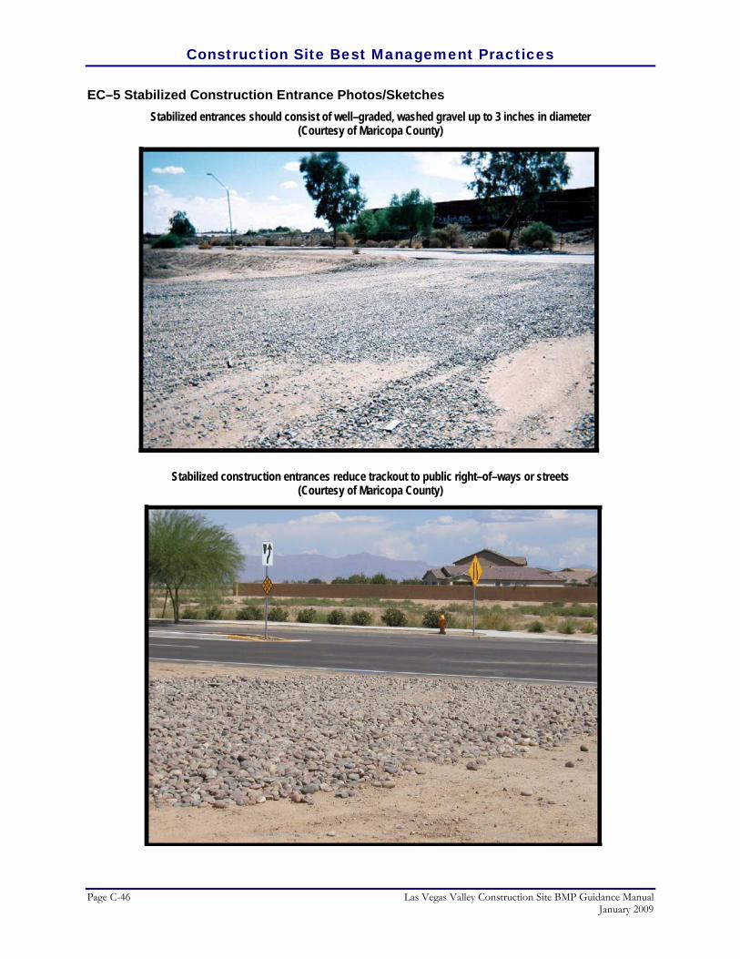
Construction Site Best Management Practices
Page C-46 Las Vegas Valley Construction Site BMP Guidance Manual January 2009
EC–5 Stabilized Construction Entrance Photos/Sketches Stabilized entrances should consist of well–graded, washed gravel up to 3 inches in diameter
(Courtesy of Maricopa County)
Stabilized construction entrances reduce trackout to public right–of–ways or streets (Courtesy of Maricopa County)

Construction Site Best Management Practices
Las Vegas Valley Construction Site BMP Guidance Manual Page C-47 January 2009
EC–5 Stabilized Construction Entrance Drawing
(Courtesy of Caltrans)

Construction Site Best Management Practices
Page C-48 Las Vegas Valley Construction Site BMP Guidance Manual January 2009
Construction Road Stabilization
Definition
The temporary stabilization of the subgrade, sub–base, and base of access roads, subdivision roads, parking areas, and other on-site vehicle transportation routes for dust and erosion control.
RATINGS Associated Costs H M L
Implementation
Maintenance
Training
Target Pollutants Removal H M L
Oil and Grease
Nutrients
Sediment
Floatable Material
Metals
Other Construction Waste
GENERAL INFORMATION FIGURES Applicability – Effectiveness: • Applicability – Effectiveness: • Slope Protection – moderate • Perimeter and Access Controls – high Most effective when used with: • GH–4 Designated Washdown Areas • EC–5 Stabilized Construction Entrance • EC–7 Dust Control for additional erosion and
fugitive dust control Alternative BMPs: • For light traffic, dust suppressants in EC–7 Dust
Control can be used for topical stabilization. • For roadways crossing waterways, use EC–8
Temporary Access Waterway Crossing
Photos/Sketches:• EC–6 Construction Road Stabilization Photos CAD Drawings: • None
Purpose
Roads graded for construction vehicles are especially susceptible to erosion. The exposed soil surface is continually disturbed resulting in erosion, dust problems, and loss of sediment–laden runoff. During wet weather, the roads may generate significant quantities of sediment that may be transported off-site in surface runoff or on the wheels of construction vehicles. Stabilization helps to increase the compressive strength and durability of access roads. Stabilization also helps limit dust and erosion created by vehicular tracking and creates easier and safer driving conditions for construction vehicles and equipment.
EC-6

Construction Site Best Management Practices
Las Vegas Valley Construction Site BMP Guidance Manual Page C-49 January 2009
Appropriate Applications
• Parking areas (both permanent and temporary) for use by construction traffic
• For phased construction projects where roadways are graded for utility installations, but will not be paved immediately.
• Detour roadways.
• When roadway construction occurs in wet weather.
Limitations
• Measures on temporary roads must be cheap to install and remove
• Aggregate or chemical stabilization to construction roads may need to be applied more than once during a construction period.
• All unpaved construction roads will generate airborne dust. The contractor should control dust, refer to Dust Control for strategies to control dust including the suite of chemical stabilization methods.
Planning Considerations
Construction Road Stabilization can be enhanced when implemented with Designated Wash–down Areas, Stabilized Construction Entrance, and Dust Control.
Recommended Standards and Specifications
There are various levels of road stabilization methods that differ in costs and effectiveness. They are described in increasing order of cost:
• Dust palliative on an untreated/unimproved road. Chemical dust suppressants, or palliatives, can also act as road stabilization for light traffic and loading conditions. Refer to Commonly Used Dust Suppressants Table for an overview of these chemical treatments.
• Gravel surface road consisting of either aggregate, imported gravel, or reclaimed asphalt. Gravel, aggregate, or reclaimed asphalt will provide additional stabilization to the road surface. A 6–inch layer of crushed rock (2 – 4 inch nominal diameter), gravel base, or crushed surface base course should be applied immediately after grading or utility installation has been completed within the right–of–way. A 4–inch course of reclaimed asphalt or aggregate base course may be used in lieu of the crushed rock.
• Treated base and sub–base. The compressive strength of road base and sub–base material can be increased through chemical treatment including cement and lime/fly–ash. Lignosulfonates have also been shown to increase the compressive

Construction Site Best Management Practices
Page C-50 Las Vegas Valley Construction Site BMP Guidance Manual January 2009
strength of base and sub–base materials. Road surfaces can also be strengthened using one or more layers of bituminous material (chip seal).
• Composite road section design. Composite road section design provides the highest level of road stabilization. It also requires the highest level of design and implementation cost, time, and labor. A typical composite road section consists of a compacted native sub–grade soil, followed by a stabilized base course, followed with an unbound base, and finally a wearing surface of asphalt concrete or a Portland cement concrete pavement.
Temporary roads should follow the contour of the natural terrain to the maximum extent possible and the slope should not exceed 15 percent. Roadways should be carefully graded to drain transversely. Provide drainage swales on each side of the roadway for a normal crown section, or to the downstream side for a super–elevated section. Simple gravel berms without a trench can also be used. Installed drainage inlets should be protected to prevent sediment–laden water entering the drain sewer system (see Storm Drain Inlet Protection BMP).
Recommended Maintenance and Inspection
Inspect stabilized roads at regular intervals (a minimum of once a month) and on a more frequent basis during rainy period. Look for cracks, potholes, and other signs of road surface erosion. Add rock, gravel, or asphalt patches where necessary to prevent any exposed areas to erosion.
Post Construction Methods
Stabilized roads can be converted to a more permanent form, usually when the base and subbase has been treated or when a composite road section design has been constructed.
References
CALTRANS, State of California Department of Transportation, Construction Site Best Management Practices (BMPs) Manual, March 2003. http://www.dot.ca.gov/hq/construc/stormwater/manuals.htm
North Carolina State University (NCSU), North Carolina Nonpoint Source Pollution Control
North Carolina State University, (NCSU) North Carolina Nonpoint Source Pollution Control Measures http://h2osparc.wq.ncsu.edu/info/bmps.html
Tacoma Public Works Environmental Services, City of Tacoma Surface Water Management Manual
Volume II, Construction Stormwater Pollution Prevention, January 1993. http://www.ci.tacoma.wa.us/waterservices/permits/Manual.htm
U. S. Environmental Protection Agency, Construction Site Storm Water Runoff Control, National
Menu of Best Management Practices for Storm Water Phase II, December 1999. http://cfpub2.epa.gov/npdes/stormwater/menuofbmps/con_site.cfm
Virginia Department of Conservation and Recreation, Division of Soil and Water Conservation,
Virginia Erosion and Sedimentation Control Handbook, Third Edition, 1992.

Construction Site Best Management Practices
Las Vegas Valley Construction Site BMP Guidance Manual Page C-51 January 2009
Washington Department of Ecology, Stormwater Management Manual for Western Washington, Publications #99–11 through 99–15, August 2001.

Construction Site Best Management Practices
Page C-52 Las Vegas Valley Construction Site BMP Guidance Manual January 2009
EC–6 Construction Road Stabilization Photos/Sketches
Comparison of a haul road before and after it has been stabilized (Courtesy of Dust Pro, Inc.)
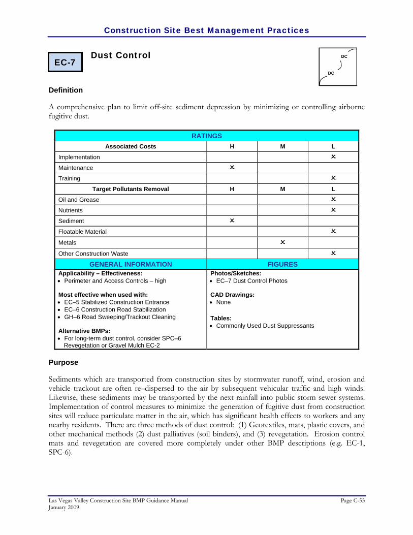
Construction Site Best Management Practices
Las Vegas Valley Construction Site BMP Guidance Manual Page C-53 January 2009
Dust Control
Definition
A comprehensive plan to limit off-site sediment depression by minimizing or controlling airborne fugitive dust.
RATINGS Associated Costs H M L
Implementation
Maintenance
Training
Target Pollutants Removal H M L
Oil and Grease
Nutrients
Sediment
Floatable Material
Metals Other Construction Waste
GENERAL INFORMATION FIGURES Applicability – Effectiveness: • Perimeter and Access Controls – high Most effective when used with: • EC–5 Stabilized Construction Entrance • EC–6 Construction Road Stabilization • GH–6 Road Sweeping/Trackout Cleaning Alternative BMPs: • For long-term dust control, consider SPC–6
Revegetation or Gravel Mulch EC-2
Photos/Sketches:• EC–7 Dust Control Photos CAD Drawings: • None Tables: • Commonly Used Dust Suppressants
Purpose
Sediments which are transported from construction sites by stormwater runoff, wind, erosion and vehicle trackout are often re–dispersed to the air by subsequent vehicular traffic and high winds. Likewise, these sediments may be transported by the next rainfall into public storm sewer systems. Implementation of control measures to minimize the generation of fugitive dust from construction sites will reduce particulate matter in the air, which has significant health effects to workers and any nearby residents. There are three methods of dust control: (1) Geotextiles, mats, plastic covers, and other mechanical methods (2) dust palliatives (soil binders), and (3) revegetation. Erosion control mats and revegetation are covered more completely under other BMP descriptions (e.g. EC-1, SPC-6).
EC-7 DC
DC
Construction Site Best Management Practices
Page C-54 Las Vegas Valley Construction Site BMP Guidance Manual January 2009
Appropriate Applications
Dust control measures should be applied at the following locations and activities:
• Grading Operations (land clearing and earthmoving) • Drilling and blasting • Batch drop operations (loader operation) • Exposed areas, cleared unstabilized area. • Vehicle traffic on unpaved surfaces • Sediment tracking on paved surfaces • Blasting and wrecking ball operations • Soil and debris storage piles
Limitations
Dust suppressants have a range of limitations and precautions. Refer to Commonly Used Dust Suppressants Table for limitations of each type of dust suppressant.
• All dust suppressants are temporary in nature and may need reapplication(s) throughout the life of a project.
• Dust suppressants require a minimum curing time until fully effective, as prescribed by the manufacturer, which may be 24 hours or longer. Reapplication may be necessary after a storm event.
• Dust suppressants will generally experience spot failures during heavy rainfall events. If runoff penetrates the soil at the top of a slope treated with a soil binder, the runoff may completely undercut the stabilized soil layer and discharge at a point further down the slope.
• Dust suppressants may not penetrate soil surfaces made up primarily of silt and clay, particularly when compacted.
• Some dust suppressants can be environmentally hazardous, especially if the dust suppressant dissolves in water. Dissolved chemicals can migrate with the runoff or percolate further below the ground surface. For additional information, refer to the EPA document, "Potential Environmental Impacts of Dust Suppressants: Avoiding Another Times Beach", referenced at the end of this BMP.
• Some dust suppressants do not perform well with low relative humidity, while others become slippery or leach out of the soil under heavy precipitation.
• Dust suppressants should always be applied in accordance with manufacturers specifications and with the guidance for dust suppression for air quality management provided by Clark County Department of Air Quality and Environmental Management.
Construction Site Best Management Practices
Las Vegas Valley Construction Site BMP Guidance Manual Page C-55 January 2009
Planning Considerations
Many of the reasonably available control measures for controlling fugitive dust from construction sites can also be implemented as Best Management Practices for stormwater pollution prevention. Those best management practices include:
• Pave, vegetate, or chemically stabilize access points to paved roads.
• Provide covers for trucks transporting materials that contribute dust.
• Provide for wet suppression or chemical stabilization of exposed soils.
• Provide for rapid cleanup of sediments deposited on paved roads.
• Furnish stabilized construction road entrances and vehicle wash down areas.
• Stabilize unpaved haul roads, parking and staging areas.
• Implement dust control measures for material stockpiles.
• Prevent drainage of sediment–laden stormwater onto paved surfaces.
• Stabilize abandoned construction sites using vegetation or chemical stabilization methods.
• Limit the amount of areas disturbed by clearing and earth moving operations by scheduling these activities in phases.
Recommended Standards and Specifications
There are many products available as dust suppressants. For chemicals available and recommendations for their use, see the Commonly Used Dust Suppressants Table. In many applications, water is the most cost-effective dust suppressant. When water is used, care should be taken to apply at sufficient frequencies to maintain a damp surface. Any runoff of water used as a dust suppressant should be avoided. Clark County has adopted comprehensive dust control ordinances and regulations that establish policies for mitigating dust production from construction sites. These policies should be carefully followed in conjunction with the Dust Control stormwater BMP.
Recommended Maintenance and Inspection
Dust control is an ongoing process during site construction. Re–application of dust control measure may be necessary until construction is complete.
Construction Site Best Management Practices
Page C-56 Las Vegas Valley Construction Site BMP Guidance Manual January 2009
Post Construction Methods
Consider Revegetation or emulsion chip seals for more permanent dust control after the construction project has been completed.
References
CALTRANS, State of California Department of Transportation, Construction Site Best Management Practices (BMPs) Manual, March 2003. http://www.dot.ca.gov/hq/construc/stormwater/manuals.htm
North Central Texas Council of Governments, Integrated Storm Water Management (iSWM) Design
Manual for Construction, December 2003. Tacoma Public Works Environmental Services, City of Tacoma Surface Water Management Manual
Volume II, Construction Stormwater Pollution Prevention, January 1993. http://www.ci.tacoma.wa.us/waterservices/permits/Manual.htm
U. S. Environmental Protection Agency, Construction Site Storm Water Runoff Control, National Menu of
Best Management Practices for Storm Water Phase II, December 1999. http://cfpub2.epa.gov/npdes/stormwater/menuofbmps/con_site.cfm
---- Nevada Potential Environmental Impacts of Dust Suppressants: “Avoiding Another Times Beach” An
Expert Panel Summary, Las Vegas, May 30–31, 2002.

Construction Site Best Management Practices
Las Vegas Valley Construction Site BMP Guidance Manual Page C-57 January 2009
EC–7 Dust Control Photos/Sketches
Wind blown dust (Courtesy of Maricopa County)

Construction Site Best Management Practices
Page C-58 Las Vegas Valley Construction Site BMP Guidance Manual January 2009
EC–7 Dust Control Table
Commonly Used Dust Suppressants
TYPES FUNCTIONAL MECHANISM ADVANTAGES LIMITATIONS
Freshwater Moisture wets particles, thereby increasing their mass and binding them together.
Usually readily available, low material cost, and easy to supply
Frequent light applications may be necessary during hot dry weather and can be labor intensive. Over application may result in loss of traction, erosion, or points of road failure.
Calcium Chloride
At a relative humidity greater than approximately 30% (77° F), the salts within the soil will pull moisture from the air above and retain it in the soil.
Reduces evaporation rate of surface moisture, lowers the freezing point of water, which reduces frost heave and freeze–thaw cycles, thereby reducing required road maintenance. Calcium Chloride also increases the compacted density of existing road base material. Effectiveness is retained after reblading.
Effectiveness in arid and semi–arid regions may be limited due to low relative humidity. It is very corrosive to aluminium alloys and slightly corrosive to steel. Solubility of calcium chloride results in leaching during heavy precipitation.
Magnesium Chloride
At a relative humidity greater than approximately 30% (77°F), the salts within the soil will pull moisture from the air above and retain it in the soil.
Reduces evaporation rate of surface moisture, lowers the freezing point of water, which reduces frost heave and freeze–thaw cycles, thereby reducing required road maintenance. Magnesium Chloride increases the compacted density of existing road base material more than Calcium Chloride. Effectiveness is retained after reblading.
Effectiveness in arid and semi–arid regions may be limited due to low relative humidity. It is very corrosive to aluminium alloys and slightly corrosive to steel. Solubility of calcium chloride results in leaching during heavy precipitation.
Lignin Derivatives
Act as adhesives by binding soil particles together and curing.
Greatly increases dry strength of soil, not humidity–dependent, imparts some plasticity to road surfaces, and lowers freezing point of road surface and base. Effectiveness is retained after reblading.
High solubility results in leaching during heavy precipitation. It is corrosive to aluminium alloys due to acidity (CaCO3 can neutralize the acidity). Proper aggregate mix is important to performance. Becomes slippery when wet and brittle when dry.
Tree Resin Emulsions (tall oil)
Act as adhesives by binding soil particles together and curing.
Low solubility after curing minimizes leaching and provides degree of surface waterproofing. Imparts some plasticity to road surfaces, has a high bonding strength, and is non–corrosive.
Requires proper weather and time to cure. No residual effectiveness after reblading. Equipment requires prompt cleanup to avoid curing of resin in hoses and pipes.
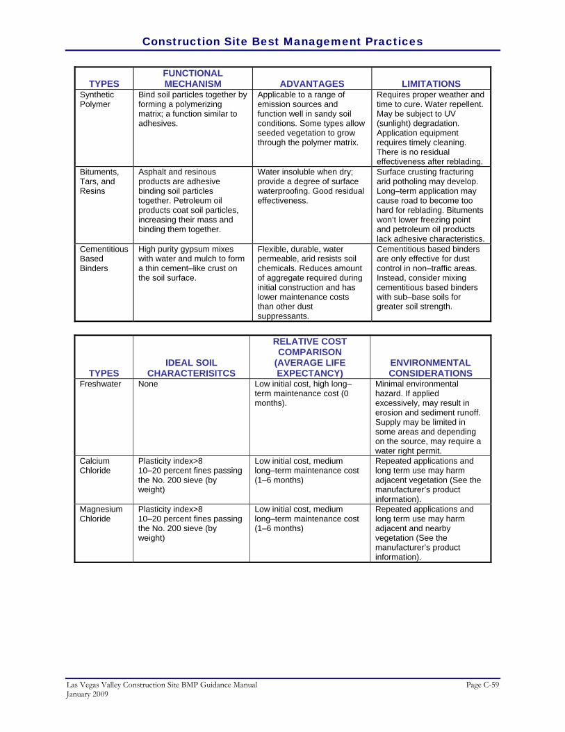
Construction Site Best Management Practices
Las Vegas Valley Construction Site BMP Guidance Manual Page C-59 January 2009
TYPES FUNCTIONAL MECHANISM ADVANTAGES LIMITATIONS
Synthetic Polymer
Bind soil particles together by forming a polymerizing matrix; a function similar to adhesives.
Applicable to a range of emission sources and function well in sandy soil conditions. Some types allow seeded vegetation to grow through the polymer matrix.
Requires proper weather and time to cure. Water repellent. May be subject to UV (sunlight) degradation. Application equipment requires timely cleaning. There is no residual effectiveness after reblading.
Bituments, Tars, and Resins
Asphalt and resinous products are adhesive binding soil particles together. Petroleum oil products coat soil particles, increasing their mass and binding them together.
Water insoluble when dry; provide a degree of surface waterproofing. Good residual effectiveness.
Surface crusting fracturing arid potholing may develop. Long–term application may cause road to become too hard for reblading. Bituments won’t lower freezing point and petroleum oil products lack adhesive characteristics.
Cementitious Based Binders
High purity gypsum mixes with water and mulch to form a thin cement–like crust on the soil surface.
Flexible, durable, water permeable, arid resists soil chemicals. Reduces amount of aggregate required during initial construction and has lower maintenance costs than other dust suppressants.
Cementitious based binders are only effective for dust control in non–traffic areas. Instead, consider mixing cementitious based binders with sub–base soils for greater soil strength.
TYPES IDEAL SOIL
CHARACTERISITCS
RELATIVE COST COMPARISON
(AVERAGE LIFE EXPECTANCY)
ENVIRONMENTAL CONSIDERATIONS
Freshwater None Low initial cost, high long–term maintenance cost (0 months).
Minimal environmental hazard. If applied excessively, may result in erosion and sediment runoff. Supply may be limited in some areas and depending on the source, may require a water right permit.
Calcium Chloride
Plasticity index>8 10–20 percent fines passing the No. 200 sieve (by weight)
Low initial cost, medium long–term maintenance cost (1–6 months)
Repeated applications and long term use may harm adjacent vegetation (See the manufacturer’s product information).
Magnesium Chloride
Plasticity index>8 10–20 percent fines passing the No. 200 sieve (by weight)
Low initial cost, medium long–term maintenance cost (1–6 months)
Repeated applications and long term use may harm adjacent and nearby vegetation (See the manufacturer’s product information).

Construction Site Best Management Practices
Page C-60 Las Vegas Valley Construction Site BMP Guidance Manual January 2009
TYPES IDEAL SOIL
CHARACTERISITCS
RELATIVE COST COMPARISON
(AVERAGE LIFE EXPECTANCY)
ENVIRONMENTAL CONSIDERATIONS
Lignin Derivatives
Plasticity index>8 10–30 percent fines passing the No. 200 sieve (by weight)
Medium initial cost, low long–term maintenance cost (3–12 months)
Lignin products have high BOD (biological oxygen demand) in aquatic systems. Spills or runoff into surface or groundwaters may create low dissolved oxygen conditions resulting in fish kills or increases in ground water concentrations of iron, sulfur compounds arid other pollutants. (See the product MSDS for specific information).
Tree Resin Emulsions (tall oil)
Plasticity index<3 10–20 percent fines passing the No. 200 sieve (by weight)
Medium initial cost, low long–term maintenance cost (1–6 months)
(See the manufacturer’s product information)
Synthetic Polymer
Plasticity index<3 5–20 percent fines passing the No. 200 sieve (by weight)
High initial cost, low long–term maintenance cost (1–3 months)
(See the manufacturer’s product information)
Bituments, Tars, and Resins
Plasticity index<3 <20 percent fines passing the No. 200 sieve (by weight)
High initial cost, low long–term maintenance cost (1–3 months)
Use of soils prohibited. Some petroleum based products may contain carcinogenic polycyclic aromatic hydrocarbons (PAHs). (See the manufacturer’s product information)
Cementitious Based Binders
Depending on type of cementitious based binder, will work with both high and low plasticity index soils.
Low initial cost, medium long–term maintenance cost (3–6 months)
None

Construction Site Best Management Practices
Las Vegas Valley Construction Site BMP Guidance Manual Page C-61 January 2009
Temporary Access Waterway Crossing
Definition
A temporary access stream crossing is a structure placed across a waterway to provide access for construction purposes for a period of less than one year.
RATINGS Associated Costs H M L
Implementation
Maintenance
Training
Target Pollutants Removal H M L
Oil and Grease
Nutrients
Sediment
Floatable Material
Metals
Other Construction Waste
GENERAL INFORMATION FIGURES Applicability – Effectiveness: • Inlet Drain Protection – high • Debris Management, Cleanup and Washout – high Most effective when used with: • None Alternative BMPs: • None
Photos/Sketches:• EC–8 Temporary Access Waterway Crossing
Photos CAD Drawings: • Temporary Access Culvert • Temporary Access Ford
Purpose
The purpose of the temporary access waterway crossing is to provide a safe, pollution free access across a stream. Temporary access waterway crossings are necessary to prevent construction equipment from damaging the stream and tracking sediment and other pollutants into the waterway.
Appropriate Applications
Temporary stream crossings are installed at sites:
• Where appropriate permits have been secured (404 Permits and/or 401 Certification).
• Where construction equipment or vehicles need to frequently cross a waterway.
EC-8

Construction Site Best Management Practices
Page C-62 Las Vegas Valley Construction Site BMP Guidance Manual January 2009
• When alternate access routes that do not cross streams impose significant constraints to the project
• Construction activities will not last longer than one year.
There are two main temporary access waterway crossings that are generally constructed:
• Temporary access culverts – are effective in controlling erosion, easily constructed, and allow for heavy equipment loading.
• Temporary access fords – offer very little sediment and erosion control and are only effective in ephemeral stream channels. Temporary fords are the least expensive waterway crossing, allow for maximum load limits, and require minimal maintenance.
Limitations
• Temporary access culverts – often require maintenance and can cause erosion if stream flow is restricted. Culverts usually disturb the waterway during installation and removal.
• Temporary access fords – offer little erosion control.
• May require section 401 and 404 certification of the Clean Water Act prior to installing a temporary access ford.
• Special care must be taken for all these practices when crossing an environmentally sensitive stream. Oils or other potentially hazardous materials should not be used for surface treatments.
Planning Considerations
• Most streams within the Las Vegas Valley will be flowing only after moderate to heavy rainfalls. For minor washes, no crossing may be necessary. For larger streams, the contractor should consider the time of year, construction schedule and construction requirements. For crossing intermittently flowing streams, a shallow access ford or culvert is recommended. Temporary culverts must be sized and installed per the requirements of the Clark County Regional Flood Control District and/or local municipal stormwater agency.
• Construction in dry streams should be at or near the natural invert of the streambed to prevent flooding upstream of the crossing. Construction in waterways may be subject to additional permit requirements. Contact the Clark County Regional Flood Control District and/or local municipal stormwater agency for information.

Construction Site Best Management Practices
Las Vegas Valley Construction Site BMP Guidance Manual Page C-63 January 2009
Recommended Standards and Specifications
Temporary culverts should be sized and installed per the requirements of the Clark County Regional Flood Control District’s Hydrologic Criteria and Drainage Design Manual.
Recommended Maintenance and Inspection
• Periodically remove debris behind fords, in culverts, and under bridges.
• Replace protective aggregate from culvert inlets and outlets that were eroded and lost during a storm.
• Remove a temporary crossing promptly when it is no longer needed.
• Check for structural weakening of the temporary crossing, such as cracks, and undermining of foundations and abutments.
• Inspect, at a minimum, weekly and after each significant rainfall. The inspection should include:
• Checking for blockage in the channel, debris buildup in culverts or fords, and under bridges or trapped debris.
• Checking for erosion of abutments, channel scour, riprap displacement, or piping in the soil.
Post Construction Methods
Fords are only temporary waterway crossings and the stream must be returned to the original natural state as it was prior to construction. Temporary access culverts may remain permanent, per the requirements of the Clark County Regional Flood Control District and/or the local municipal stormwater agency.
References
CALTRANS, State of California Department of Transportation, Construction Site Best Management Practices (BMPs) Manual, March 2003. http://www.dot.ca.gov/hq/construc/stormwater/manuals.htm
North Carolina Department of Transportation, Best Management Practices for Construction and
Maintenance Activities, Chapter 5.0 Operation Best Management Practices, August 2003 http://www.doh.dot.state.nc.us/operations/BMP_manual/
U. S. Environmental Protection Agency, Construction Site Storm Water Runoff Control, National Menu of
Best Management Practices for Storm Water Phase II, December 1999. http://cfpub2.epa.gov/npdes/stormwater/menuofbmps/con_site.cfm

Construction Site Best Management Practices
Page C-64 Las Vegas Valley Construction Site BMP Guidance Manual January 2009
EC–8 Temporary Access Waterway Crossing Photos/Sketches
Schematic of temporary access culvert (Courtesy of CALTRANS)
Temporary access culvert (Courtesy of NCDOT)

Construction Site Best Management Practices
Las Vegas Valley Construction Site BMP Guidance Manual Page C-65 January 2009
EC–8 Temporary Access Waterway Crossing Drawing
(Courtesy of Maricopa County)

Construction Site Best Management Practices
Page C-66 Las Vegas Valley Construction Site BMP Guidance Manual January 2009
(Courtesy of Maricopa County)
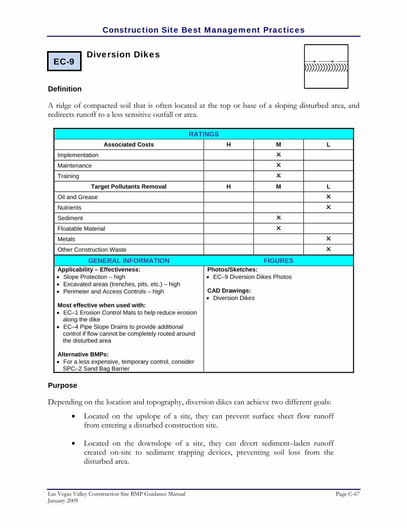
Construction Site Best Management Practices
Las Vegas Valley Construction Site BMP Guidance Manual Page C-67 January 2009
Diversion Dikes
Definition
A ridge of compacted soil that is often located at the top or base of a sloping disturbed area, and redirects runoff to a less sensitive outfall or area.
RATINGS Associated Costs H M L
Implementation
Maintenance
Training
Target Pollutants Removal H M L
Oil and Grease
Nutrients
Sediment
Floatable Material
Metals
Other Construction Waste
GENERAL INFORMATION FIGURES Applicability – Effectiveness: • Slope Protection – high • Excavated areas (trenches, pits, etc.) – high • Perimeter and Access Controls – high Most effective when used with: • EC–1 Erosion Control Mats to help reduce erosion
along the dike • EC–4 Pipe Slope Drains to provide additional
control if flow cannot be completely routed around the disturbed area
Alternative BMPs: • For a less expensive, temporary control, consider
SPC–2 Sand Bag Barrier
Photos/Sketches:• EC–9 Diversion Dikes Photos CAD Drawings: • Diversion Dikes
Purpose
Depending on the location and topography, diversion dikes can achieve two different goals:
• Located on the upslope of a site, they can prevent surface sheet flow runoff from entering a disturbed construction site.
• Located on the downslope of a site, they can divert sediment–laden runoff created on-site to sediment trapping devices, preventing soil loss from the disturbed area.
EC-9

Construction Site Best Management Practices
Page C-68 Las Vegas Valley Construction Site BMP Guidance Manual January 2009
Appropriate Applications
Diversion dikes may be used to:
• Intercept and divert runoff to avoid sheet flow over sloped surfaces.
• Divert and direct runoff towards a stabilized watercourse, drainage pipe or channel.
• Intercept runoff from paved surfaces. Diversion dikes may be installed:
• Below steep grades where runoff begins to concentrate.
• Along roadways and facility improvements subject to flood drainage.
• At the top of slopes to divert runon from adjacent or undisturbed slopes.
• At bottom and mid–slope locations to intercept sheet flow and convey concentrated flows.
Limitations
• Limit to upstream drainage areas of 10 acres or less and for slopes less than 5 percent. For larger areas more permanent structures should be built.
• All structures should be in compliance with hydraulic design standards set by the local municipality or Clark County Regional Flood Control District.
• Earth dikes may create more disturbed area on site and become barriers to construction equipment.
• Earth dikes must be stabilized immediately which increases maintenance and installation costs.
• Diverted stormwater flow may cause flood damage to adjacent areas.
• Diversion dikes are not suitable as sediment trapping devices.
• The concentrated runoff in a channel or ditch has increased erosion potential. To alleviate this erosion capability, diversion dikes must be used in conjunction with sediment trapping devices, soil stabilization, and sediment controls.
Planning Considerations
Several considerations must be made before installing diversion dikes. Diversion dikes can either be installed temporarily or as a permanent structure:

Construction Site Best Management Practices
Las Vegas Valley Construction Site BMP Guidance Manual Page C-69 January 2009
Temporary diversion dikes are generally made up of earth material. Earth dikes are advantageous because they can handle flows from large drainage areas, are relatively inexpensive and easy to install, use on-site materials, and once stabilized, earth dikes require little maintenance. However, earth dikes, alone, do not control erosion or remove sediment from runoff. Rather, they direct runoff to an erosion control device such as a Temporary Sediment basin or a Temporary Sediment Trap, or away from an erodible surface. Temporary diversion dikes should not adversely impact adjacent properties and must conform to local floodplain management regulations. For large flows, earth dikes can begin to erode and further contribute to the sediment loading in the runoff. Stone, recycled concrete, rip–rap, or filter cloth can be used to temporarily stabilize a diversion dike (see Recommended Standards and specifications below). Consider using Erosion Control Mats and Pipe Slope Drains in conjunction with Sand Bag Barriers for additional erosion control and stabilization.
Recommended Standards and Specifications
• All dikes should be compacted by earth–moving equipment.
• All dikes should have positive drainage to an outlet.
• Top width may be wider and side slopes may be flatter if desired to facilitate crossing by construction traffic.
• Runoff should be conveyed to a sediment trapping device such as a sediment trap or sediment basin when either the dike channel or the drainage area above the dike are not adequately stabilized.
• Temporary stabilization, when necessary, should be as specified below:
• Stone or recycled concrete equivalent, should be applied in a layer at least 8 inches in thickness and be pressed into the soil with construction equipment.
• Rip–rap should be applied in a layer at least two times the D50 and pressed into the soil.
• Approved equivalents can be substituted for any of the above materials.
• Filter cloth and erosion control mats may be used for dikes in use for long periods.
Recommended Maintenance and Inspection
• Inspect temporary measures prior to predicted rainfall events, after rainfall events, and regularly during the rainy season.
• Inspect ditches and berms for washouts. Replace lost riprap, damaged linings or soil stabilizers as needed.
Construction Site Best Management Practices
Page C-70 Las Vegas Valley Construction Site BMP Guidance Manual January 2009
Post Construction Methods
By providing surface stabilization to the diversion dike, the dike can become a permanent structure.
References
CALTRANS, State of California Department of Transportation, Construction Site Best Management Practices (BMPs) Manual, March 2003. http://www.dot.ca.gov/hq/construc/stormwater/manuals.htm
Center for Watershed Protection, Inc., Stormwater Manager’s Resource Center (SMRC).
http://www.stormwatercenter.net/ Kamber Engineering, Gaithersburg, Maryland, Sedimentation and Erosion Control, An Inventory of Current
Practices, USEPA, April, 1991. North Carolina Department of Transportation, Best Management Practices for Construction and
Maintenance Activities, Chapter 5.0 Operation Best Management Practices, August 2003. http://www.doh.dot.state.nc.us/operations/BMP_manual/
North Central Texas Council of Governments, Integrated Storm Water Management (iSWM) Design
Manual for Construction, December 2003. Tacoma Public Works Environmental Services, City of Tacoma Surface Water Management Manual
Volume II, Construction Stormwater Pollution Prevention, January 1993. http://www.ci.tacoma.wa.us/waterservices/permits/Manual.htm
U. S. Environmental Protection Agency, Construction Site Storm Water Runoff Control, National Menu of
Best Management Practices for Storm Water Phase II, December 1999. http://cfpub2.epa.gov/npdes/stormwater/menuofbmps/con_site.cfm

Construction Site Best Management Practices
Las Vegas Valley Construction Site BMP Guidance Manual Page C-71 January 2009
EC–9 Diversion Dikes Photos/Sketches
A temporary diversion dike can be stabilized with straw mulching (Courtesy of Douglas County)
Permanent diversion dikes can be constructed of grouted riprap and vegetated (Courtesy of Maricopa County)

Construction Site Best Management Practices
Page C-72 Las Vegas Valley Construction Site BMP Guidance Manual January 2009
EC–9 Diversion Dikes Drawing
(Courtesy of Maricopa County)

Construction Site Best Management Practices
Las Vegas Valley Construction Site BMP Guidance Manual Page C-73 January 2009
Drainage Swales
Definition
A drainage way with a lining of grass, stone, asphalt, concrete, or other material. Permanent channels must be designed and constructed in accordance with appropriate local design standards.
RATINGS Associated Costs H M L
Implementation
Maintenance
Training
Target Pollutants Removal H M L
Oil and Grease
Nutrients
Sediment
Floatable Material
Metals
Other Construction Waste
GENERAL INFORMATION FIGURES Applicability – Effectiveness: • Slope Protection – high • Excavated areas (trenches, pits, etc.) – high • Perimeter and Access Controls – high • Channels and Medians – high Most effective when used with: • EC–11 Outlet Protection, Velocity Dissipation
Devices • EC–1 Erosion Control Mats • SPC–4 Check Dams • All of the above provide erosion control for higher
flows Alternative BMPs: • EC–9 Diversion Dikes
Photos/Sketches:• EC–10 Drainage Swales Photos CAD Drawings: • Drainage Swales
Purpose
Drainage swales are used as perimeter controls or slope protection to convey runoff without causing erosion by intercepting runoff from above unprotected slopes or at the perimeter and directing the runoff to a sediment trapping device or stabilized outlet. Depending on the design of the drainage swale, different objectives can be achieved. A meandering or winding swale with vegetation helps to reduce flow velocities and reduce suspended sediments. A straight, lined swale provides the maximum conveyance of drainage flows.
EC-10

Construction Site Best Management Practices
Page C-74 Las Vegas Valley Construction Site BMP Guidance Manual January 2009
Appropriate Applications
Drainage swales and lined ditches may be used to:
• Convey surface runoff down sloping land.
• Intercept and divert runoff to avoid sheet flow over sloped surfaces.
• Divert and direct runoff towards a stabilized watercourse, drainage pipe or treatment facility.
• Intercept runoff from paved surfaces. Drainage swales and lined ditches may be used:
• Below steep grades where runoff begins to concentrate.
• Along roadways and facility improvements subject to flood drainage.
• At the top of slopes to divert runon from adjacent or undisturbed slopes.
• At bottom and mid–slope locations to intercept sheet flow and convey concentrated flows.
Limitations
• Temporary drainage swales or any diversion of runoff should not adversely impact upstream or downstream properties and must conform to local floodplain management regulations.
• Constructing the proper swale to handle the desired runoff flows often requires engineering design work which can be costly.
• Swales can be expensive to construct if a liner is required.
• Interceptor swales must be stabilized quickly upon excavation in order not to contribute further to the sediment loading.
Planning Considerations
Consider using Outlet Protection, Velocity Dissipation Devices, Erosion Control Mats, and Check Dams in conjunction with Drainage Swales to provide erosion control for higher flow rates.
Recommended Standards and Specifications
Once the proper geometry and lining is used in a drainage swale, large volumes of flows can be effectively conveyed and/or treated with little maintenance. Velocity dissipation devices should be installed at the beginning or end of the swale to prevent erosion or scour.

Construction Site Best Management Practices
Las Vegas Valley Construction Site BMP Guidance Manual Page C-75 January 2009
Design and Sizing Criteria: The Clark County Regional Flood Control District’s Hydrologic Criteria and Drainage Design Manual will be used for all appropriate design criteria. In addition:
• All temporary swales should have uninterrupted grade to an outlet.
• Diverted runoff from a disturbed area should be conveyed to a sediment trapping device.
• Diverted runoff from an undisturbed area should outlet directly into an undisturbed stabilized area at non–erosive velocity.
• All trees, brush, stumps, and obstructions, may need to be removed and disposed of so as not to interfere with the proper functioning of the swale, but can remain for sediment filtration.
• The swale should be excavated or shaped to line, grade, and cross section as required to meet the criteria specified herein and be free of bank projections or other irregularities which will impede normal flow.
• Fills should be compacted by earth moving equipment.
• All earth removed and not needed on construction should be placed so that it will not interfere with the functioning of the swale.
Note: Refer to the drainage swale CAD drawing file for specified dimensions.
Recommended Maintenance and Inspection
• Inspect temporary measures prior to predicted rainfall events, after rainfall events, and regularly during the rainy season.
• Inspect ditches and berms for washouts. Replace lost riprap, damaged linings or soil stabilizers as needed.
• Inspect channel linings, embankments, and beds of ditches and berms for erosion and accumulation of debris and sediment. Remove debris and sediment, and repair linings and embankments as needed.
• Temporary conveyances should be completely removed as soon as the surrounding drainage area has been stabilized, or at the completion of construction.
Post Construction Methods
By providing a vegetated cover or other method of surface stabilization to the diversion swale, the swale can become a permanent structure.

Construction Site Best Management Practices
Page C-76 Las Vegas Valley Construction Site BMP Guidance Manual January 2009
References
CALTRANS, State of California Department of Transportation, Construction Site Best Management Practices (BMPs) Manual, March 2003. http://www.dot.ca.gov/hq/construc/stormwater/manuals.htm
Center for Watershed Protection, Inc., Stormwater Manager’s Resource Center (SMRC).
Http://www.stormwatercenter.net/ Kamber Engineering, Gaithersburg, Maryland, Sedimentation and Erosion Control, An Inventory of Current
Practices, USEPA, April, 1991. North Central Texas Council of Governments, Integrated Storm Water Management (iSWM) Design
Manual for Construction, December 2003 Tacoma Public Works Environmental Services, City of Tacoma Surface Water Management Manual
Volume II, Construction Stormwater Pollution Prevention, January 1993. http://www.ci.tacoma.wa.us/waterservices/permits/Manual.htm
U. S. Environmental Protection Agency, Construction Site Storm Water Runoff Control, National Menu of
Best Management Practices for Storm Water Phase II, December 1999. http://cfpub2.epa.gov/npdes/stormwater/menuofbmps/con_site.cfm
Washington Department of Ecology, Stormwater Management Manual for Western Washington,
Publications #99–11 through 99–15, August 2001.

Construction Site Best Management Practices
Las Vegas Valley Construction Site BMP Guidance Manual Page C-77 January 2009
EC–10 Drainage Swales Photos/Sketches
When possible, leave existing vegetation in the drainage swale for added velocity reduction (Courtesy of Maricopa County)
Permanent drainage swales are often vegetated (Courtesy of Maricopa County)

Construction Site Best Management Practices
Page C-78 Las Vegas Valley Construction Site BMP Guidance Manual January 2009
EC–10 Drainage Swales Drawing
(Courtesy of Maricopa County)

Construction Site Best Management Practices
Las Vegas Valley Construction Site BMP Guidance Manual Page C-79 January 2009
Outlet Protection, Velocity Dissipation Devices
Definition
Structures and devices placed at pipe outlets to prevent scour and reduce the velocity and/or energy of stormwater flows. These structures may include a section of rock, grouted riprap, and concrete rubble placed at the outlet end of culverts, conduits, or channels. Various products can also be installed for velocity reduction including hydrobrakes, vortex valves, and drop shafts.
RATINGS Associated Costs H M L
Implementation
Maintenance
Training
Target Pollutants Removal H M L
Oil and Grease
Nutrients
Sediment
Floatable Material
Metals
Other Construction Waste
GENERAL INFORMATION FIGURES Applicability – Effectiveness: • Perimeter and Access Controls – high Most effective when used with: • None Alternative BMPs: • None
Photos/Sketches:• EC–11 Outlet Protection, Velocity Dissipation
Devices Photos CAD Drawings: • Pipe Outlet Conditions
Purpose
Outlet protection and velocity dissipation reduces the velocity and energy of the runoff water, thereby preventing the flow from eroding the receiving downstream reach.
Appropriate Applications
• Outlet protection and velocity dissipation can be used at the following locations:
• Outlets of pipes, drains, culverts, slope drains, diversion ditches, swales, conduits or channels.
• Outlets located at the bottom of mild to steep slopes.
• Discharge outlets that carry continuous flows of water.
EC-11

Construction Site Best Management Practices
Page C-80 Las Vegas Valley Construction Site BMP Guidance Manual January 2009
• Outlets subject to short, intense flows of water, such as flash floods.
• Points where lined conveyances discharge to unlined conveyances. Note: Rock outlet protection is usually less expensive and easier to install than concrete aprons or other energy dissipators.
Limitations
Rock outlet protection may need continual maintenance because large storms often wash away the stone and leave the area susceptible to erosion.
• Loose rock may have stones washed away during high flows.
• If there is not adequate drainage, and water builds up behind grouted riprap, it may cause the grouted riprap to break up due to the resulting hydrostatic pressure.
Planning Considerations
Rock outlet protection is effective when the rock is sized and placed properly. When this is accomplished, rock outlets do much to limit erosion at pipe outlets. If runoff is sediment–laden, a sediment trap below the pipe outlet is recommended. Permanent rock riprap protection should be designed and sized by the engineer as part of the culvert, conduit or channel design.
Recommended Standards and Specifications
General recommendations for rock size and length of outlet protection mat are shown in the CAD drawing figure. When outlet protection measures are incorporated into permanent drainage solutions, they should be designed in accordance with CCRFCD HCDDM criteria.
Recommended Maintenance and Inspection
• Inspect temporary measures prior to the rainy season, after rainfall events, and regularly during the rainy season.
• Inspect apron for displacement of the riprap and/or damage to the underlying fabric. Repair fabric and replace riprap that has washed away.
• Inspect for scour beneath the riprap and around the outlet. Repair damage to slopes or underlying filter fabric immediately.
• Temporary devices should be completely removed as soon as the surrounding drainage area has been stabilized, or at the completion of construction.
Construction Site Best Management Practices
Las Vegas Valley Construction Site BMP Guidance Manual Page C-81 January 2009
Post Construction Methods
Rock outlet protection and other velocity dissipation devices can remain after the construction project for long term erosion protection. However, the design engineer should consult with the local municipality or the Clark County Regional Flood Control District for specific requirements of permanent outlet protection.
References
CALTRANS, State of California Department of Transportation, Construction Site Best Management Practices (BMPs) Manual, March 2003.
http://www.dot.ca.gov/hq/construc/stormwater/manuals.htm City of Austin, Texas, Environmental Criteria Manual, March, 2004. North Carolina State University, (NCSU) North Carolina Nonpoint Source Pollution Control Measures
http://h2osparc.wq.ncsu.edu/info/bmps.html Tacoma Public Works Environmental Services, City of Tacoma Surface Water Management Manual
Volume II, Construction Stormwater Pollution Prevention, January 1993. http://www.ci.tacoma.wa.us/waterservices/permits/Manual.htm
Virginia Department of Conservation and Recreation, Division of Soil and Water Conservation,
Virginia Erosion and Sedimentation Control Handbook, Third Edition, 1992. Washington Department of Ecology, Stormwater Management Manual for Western Washington,
Publications #99–11 through 99–15, August 2001.

Construction Site Best Management Practices
Page C-82 Las Vegas Valley Construction Site BMP Guidance Manual January 2009
EC–11 Outlet Protection, Velocity Dissipation Devices Photos/Sketches
Schematic of culvert outlet protection (Courtesy of CALTRANS)
Drainage outlet protection to the shoulder of a highway (Courtesy of Maricopa County)
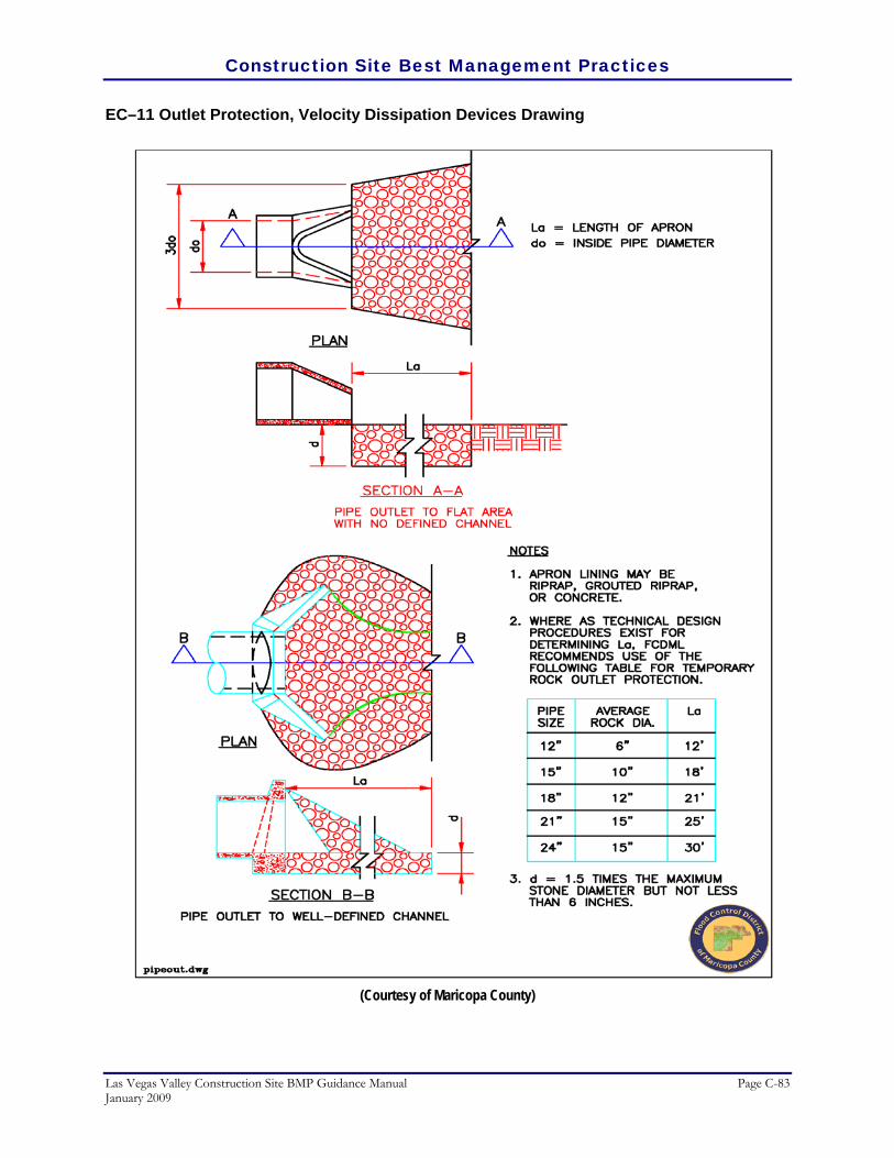
Construction Site Best Management Practices
Las Vegas Valley Construction Site BMP Guidance Manual Page C-83 January 2009
EC–11 Outlet Protection, Velocity Dissipation Devices Drawing
(Courtesy of Maricopa County)

Construction Site Best Management Practices
Page C-84 Las Vegas Valley Construction Site BMP Guidance Manual January 2009
Surface Roughening
Definition
A temporary erosion control practice often used in conjunction with grading. Soil roughening involves increasing the relief of a bare soil surface with horizontal grooves, stair–stepping (running parallel to the contour of the land), or tracking using construction equipment. Slopes that are not fine graded and that are left in a roughened condition can also reduce erosion.
RATINGS Associated Costs H M L
Implementation
Maintenance
Training
Target Pollutants Removal H M L
Oil and Grease
Nutrients
Sediment
Floatable Material
Metals
Other Construction Waste
GENERAL INFORMATION FIGURES Applicability – Effectiveness: • Slope Protection – moderate Most effective when used with: • EC–2 Mulching to establish vegetation • EC–9 Diversion Dikes to divert flow away from the
slope Alternative BMPs: • For inaccessible slopes/areas, use EC–1 Erosion
Control Mats • For slopes or loose soils, use EC–4 Pipe Slope
Drains
Photos/Sketches:• EC–12 Surface Roughening Photos CAD Drawings: • Stair–Stepping Cut Slopes and Grooving Slopes
Purpose
Soil roughening reduces runoff velocity, increases infiltration, reduces erosion, traps sediment, and prepares the soil for seeding and planting by giving seed an opportunity to take hold and grow.
Appropriate Applications
Soil roughening is appropriate for slopes up to 3:1 or higher than 5 vertical feet, on piles of excavated soil, and in areas with highly erodible soils. This technique is especially appropriate for soils that are frequently mowed or disturbed because roughening is relatively easy to accomplish. To slow erosion, roughening should be done as soon as possible after the vegetation has been removed
EC-12 SR
SR

Construction Site Best Management Practices
Las Vegas Valley Construction Site BMP Guidance Manual Page C-85 January 2009
from the slope. Roughening can be used with both seeding and planting and temporary mulching to stabilize an area. For steeper slopes and slopes that will be left roughened for longer periods of time, a combination of surface roughening and vegetation is appropriate. Alternatively consider terracing along steep slopes. Roughening should be performed immediately after grading activities have ceased (temporarily or permanently) in an area.
Limitations
• Soil roughening may not be compatible with dust control regulations in Las Vegas Valley, and may need to be used in conjunction with dust control measures.
• Soil roughening is not appropriate for rocky slopes.
• Soil compaction might occur when roughening with tracked machinery.
• Soil roughening is of limited effectiveness in anything more than a gentle or shallow depth rain.
• If roughening is washed away in a heavy storm, the surface will have to be re–roughened and re–seeded or revegetated.
Planning Considerations
Graded areas with smooth, hard surfaces give a false impression of "finished grading" and a job well done. It is difficult to establish vegetation on such surfaces due to reduced water infiltration and the potential for erosion. Rough slope surfaces with uneven soil and rocks left in place may appear unattractive or unfinished at first, but they encourage water infiltration, speed the establishment of vegetation, and decreased runoff velocity. Rough, loose soil surfaces give lime, fertilizer, and seed some natural coverage. Niches in the surface provide microclimates which generally provide a cooler and more favorable moisture level than hard flat surfaces; this aids seed germination. There are different methods for achieving a roughened soil surface on a slope, and the selection of an appropriate method depends upon the type of slope. Roughening methods include stair–step grading, grooving, and tracking. Factors to be considered in choosing a method are slope steepness, mowing requirements, and whether the slope is formed by cutting or filling.
1. Disturbed areas which will not require mowing may be stair–step graded, grooved, or left rough after filling.
2. Stair–step grading is particularly appropriate in soils containing large amounts of soft rock. Each "step" catches material which sloughs from above, and provides a level site where vegetation can become established. Stairs should be wide enough to work with standard earth moving equipment.

Construction Site Best Management Practices
Page C-86 Las Vegas Valley Construction Site BMP Guidance Manual January 2009
3. Areas which will be mowed should have slopes less than 3:1 and may have small furrows left by dicing, harrowing, raking, or seed–planting machinery operated on the contour.
4. It is important to avoid excessive compacting of the soil surface when scarifying. Tracking with bulldozer treads is preferable to not roughening at all, but is not as effective as other forms of roughening, as the soil surface is severely compacted and runoff is increased.
For longer slopes or where heavy equipment cannot operate, consider using Erosion Control Mats, and Pipe Slope Drains. Surface roughening is most effective when used with Mulching to establish vegetation or Diversion Dikes to divert flow away from the slope.
Recommended Standards and Specifications
Graded areas with slopes greater than 3:1 but less than 2:1 should be roughened before seeding. This can be accomplished in a variety of ways, including "track walking," or driving a crawler tractor up and down the slope, in leaving a pattern of cleat imprints parallel to slope contours. Graded areas steeper than 2:1 should be stair–stepped with benches as shown in the CAD drawing. The stair–stepping will help vegetation become established and also trap soil eroded from the slopes above. As slopes become steeper, benches can be widened to terraces.
Recommended Maintenance and Inspection
Areas need to be inspected after storms, since roughening might need to be repeated. Regular inspection of roughened slopes will indicate where additional erosion and sediment control measures are needed. If rills (small watercourses that have steep sides and are usually only a few inches deep) appear, they should be filled, graded again, and reseeded immediately. Proper dust control methods should be used.
Post Construction Methods
None.
References
CALTRANS, State of California Department of Transportation, Construction Site Best Management Practices (BMPs) Manual, March 2003. http://www.dot.ca.gov/hq/construc/stormwater/manuals.htm
North Carolina Department of Transportation, Best Management Practices for Construction and
Maintenance Activities, Chapter 5.0 Operation Best Management Practices, August 2003. http://www.doh.dot.state.nc.us/operations/BMP_manual/
North Carolina State University, (NCSU) North Carolina Nonpoint Source Pollution Control Measures.
Measures. http://h2osparc.wq.ncsu.edu/info/bmps.html

Construction Site Best Management Practices
Las Vegas Valley Construction Site BMP Guidance Manual Page C-87 January 2009
Tacoma Public Works Environmental Services, City of Tacoma Surface Water Management Manual Volume II, Construction Stormwater Pollution Prevention, January 1993. http://www.ci.tacoma.wa.us/waterservices/permits/Manual.htm
Washington Department of Ecology, Stormwater Management Manual for Western Washington,
Publications #99–11 through 99–15, August 2001.

Construction Site Best Management Practices
Page C-88 Las Vegas Valley Construction Site BMP Guidance Manual January 2009
EC–12 Surface Roughening Photos/Sketches
Creating a roughened soil surface can reduce runoff velocities and increase infiltration (Courtesy of Douglas County)

Construction Site Best Management Practices
Las Vegas Valley Construction Site BMP Guidance Manual Page C-89 January 2009
EC–12 Surface Roughening Drawings
(Courtesy of Maricopa County)

Construction Site Best Management Practices
Page C-90 Las Vegas Valley Construction Site BMP Guidance Manual January 2009
SPC Sediment and Pollutant Control Sediment and pollutant control includes methods for separating and containing suspended sediment and other construction related pollutants from the stormwater before the water leaves the project site and enters a storm drain inlet or a receiving natural water body. These methods involve constructing organic, sand, and rock barriers to filter sediment–laden runoff, protecting storm drain inlets, and constructing settling ponds. If a pre–manufactured product is to be implemented on a site for sediment or pollutant control, the contractor should always follow the manufacturer’s installation and maintenance recommendations as the primary reference for implementation.
• SPC–1 Organic Filter Barrier • SPC–2 Sand Bag Barrier • SPC–3 Gravel Filter Berms • SPC–4 Check Dams • SPC–5 Silt Fence • SPC–6 Revegetation • SPC–7 Storm Drain Inlet Protection • SPC–8 Temporary Sediment Basins • SPC–9 Temporary Sediment Traps • SPC–10 Sediment Dewatering Operations

Construction Site Best Management Practices
Las Vegas Valley Construction Site BMP Guidance Manual Page C-91 January 2009
Organic Filter Barrier
Definition
A temporary linear sediment barrier consisting of straw bales or similar material, designed to intercept and slow sediment–laden sheet flow runoff. Organic filter barriers allow sediment to settle from runoff before water leaves the construction site. Organic filter barriers include straw bales, storm wattles, and other organic filter berms.
RATINGS Associated Costs H M L
Implementation
Maintenance
Training
Target Pollutants Removal H M L
Oil and Grease
Nutrients
Sediment
Floatable Material
Metals
Other Construction Waste
GENERAL INFORMATION FIGURES Applicability – Effectiveness: • Slope Protection – moderate • Excavated Areas (trenches, pits, etc.) – high • Perimeter and Access Controls – high Most effective when used with: • SPC–8 Temporary Sediment Basins • SPC–9 Temporary Sediment Traps Alternative BMPs: • For higher flows or paved surfaces, consider rock
socks detailed under SPC–2 Sand Bag Barrier
Photos/Sketches:• SPC–1 Organic Filter Barrier Photos CAD Drawings: • Organic Filter Barrier
Purpose
Organic filter barriers reduce runoff velocity and cause deposition of the transported sediment load. They are well suited to sites with small disturbed drainage areas that are not subjected to concentrated flows and that will ultimately be seeded, sodded, or landscaped.
Appropriate Applications
Organic filter barriers are useful where there are no concentrations of water in a channel or drainage way, and where erosion would occur from sheet flow. These barriers are typically constructed:
SPC-1 OFB
OFB

Construction Site Best Management Practices
Page C-92 Las Vegas Valley Construction Site BMP Guidance Manual January 2009
• Along the perimeter of a site, around stockpiles, and parallel to a roadway to keep sediment off paved areas.
• Along streams and channels and across minor swales or ditches with small catchments.
• Below the toe of exposed and erodible slopes and down slope of exposed soil areas.
• Around above grade type temporary concrete washouts.
Limitations
Of all the organic filter barriers, straw bale barriers may be the most limited in erosion control and sediment loading reduction. The following limitations are associated with straw bale barriers.
• Suitable only for sheet flow on slopes of 2 percent or flatter and are not appropriate for drainage areas greater than one acre. Cannot be used in areas of concentrated flow, channel flow, and live streams.
• Installation and maintenance can be labor intensive.
• Degraded straw bales may fall apart when removed or left in place for extended periods due to rotting.
• Bale bindings of jute or cotton are not recommended.
• Straw bale barriers are not efficient on paved surfaces.
• Straw bale barriers are not to be used for drain inlet protection.
• Can be an attractive food source for some animals and may introduce some undesirable non–native plants to the area.
Planning Considerations
Optimal efficiency of organic filter barriers can be achieved through careful maintenance with special attention to replacing rotted or broken bales. Barriers should be constructed on a level contour to prevent concentration of flow against a small portion of the barrier. Organic filter barriers are additionally more efficient when used in conjunction with Temporary Sediment Basins and Temporary Sediment Traps. Consider using rock socks under Sand Bag Barrier for higher flows or paved surfaces.

Construction Site Best Management Practices
Las Vegas Valley Construction Site BMP Guidance Manual Page C-93 January 2009
Recommended Standards and Specifications
• Installation:
• Organic filter barriers must be installed in a trench and tightly abut adjacent bales along a line of constant elevation (along a contour line) if possible, with the last organic filter barrier turned up slope.
• Construct organic filter barriers with a set–back of at least 3 feet from the toe of a slope. Where it is determined not to be practical due to specific site conditions, the organic filter barrier may be constructed at the toe of the slope, but should be constructed as far from the toe of the slope as practical
• Limit the drainage area upstream of the barrier to 0.25 acre/100 feet of barrier and the maximum flow to any 20 foot section to less than 1 cfs.
• Limit the slope length draining to the organic filter barrier to 100 feet for average slopes of 2V:100H (2 percent) or flatter.
• If the slope exceeds 1V:10H (10 percent), the length of slope upstream of the barrier must be less than 50 feet.
• Organic filter barriers may be seeded with a seed loading of 1 pound per 10 linear feet for small berms or 2.25 lbs per 10 linear foot for larger berms.
• Specifications: See plan drawings for the required dimensions of organic filter barriers as described below.
• Materials: Organic filter barriers can either be composed entirely of straw (i.e., straw bale), or constructed of a mixture of 50 percent compost and 50 percent wood mulch (untreated woodchips less than 5 inches in length, 95 percent passing a 2 inch screen, and less than 30 percent passing a 1 inch screen.)
• Bindings: Barrier should be bound by steel wire, nylon or polypropylene string placed horizontally. Jute and cotton binding should not be used. Baling wire should be a minimum diameter of 0.06 inches. Nylon or polypropylene string should be approximately 0.08 inches in diameter with a breaking strength of no less than 80 lb force.
• Stakes: Wood stakes should be commercial quality lumber of the size and shape shown on the plans. Each stake should be free from decay, splits or cracks longer than the thickness of the stake, or other defects that would weaken the stakes and cause the stakes to be structurally unsuitable. Steel bar reinforcement should be equal to a number four designation or greater. End protection should be provided for any exposed bar reinforcement.

Construction Site Best Management Practices
Page C-94 Las Vegas Valley Construction Site BMP Guidance Manual January 2009
Recommended Maintenance and Inspection
• Inspect organic filter barriers before and after each rainfall event, and weekly for sediment accumulations and remove sediment when depth reaches one–third the barrier height.
• Replace or repair damage barriers as needed. Remove barriers or dismantle as mulching when no longer needed. Remove sediment accumulation, and clean, re–grade, and stabilize the area.
Post Construction Methods
There are no post construction uses for organic filter barriers, but filter barriers can be dismantled and used as mulching for erosion control purposes when a filter barrier is no longer needed.
References
CALTRANS, State of California Department of Transportation, Construction Site Best Management Practices (BMPs) Manual, March 2003. http://www.dot.ca.gov/hq/construc/stormwater/manuals.htm
City of Austin, Texas, Environmental Criteria Manual, March, 2004. City of Bellevue, Washington, Water Quality for Construction Businesses, First Edition, Storm and Surface
Water Utility, 1990. Fifield, J.S., Field Manual on Sediment and Erosion Control, Forester Press, Santa Barbara CA., 2002. Kamber Engineering, Gaithersburg, Maryland, Sedimentation and Erosion Control, An Inventory of Current
Practices, USEPA, April, 1991. North Central Texas Council of Governments, Integrated Storm Water Management (iSWM) Design
Manual for Construction, December 2003. Tacoma Public Works Environmental Services, City of Tacoma Surface Water Management Manual
Volume II, Construction Stormwater Pollution Prevention, January 1993. http://www.ci.tacoma.wa.us/waterservices/permits/Manual.htm
U. S. Environmental Protection Agency, Construction Site Storm Water Runoff Control, National Menu of
Best Management Practices for Storm Water Phase II, December 1999. http://cfpub2.epa.gov/npdes/stormwater/menuofbmps/con_site.cfm
Washington Department of Ecology, Stormwater Management Manual for Western Washington,
Publications #99–11 through 99–15, August 2001.

Construction Site Best Management Practices
Las Vegas Valley Construction Site BMP Guidance Manual Page C-95 January 2009
SPC–1 Organic Filter Barrier Photos/Sketches
Properly staked organic filter barrier
(Courtesy of Maricopa County)
Storm wattle (wrapped) (Courtesy of Kristar)
Use of an organic filter barrier in the highway median
(Courtesy of Maricopa County)
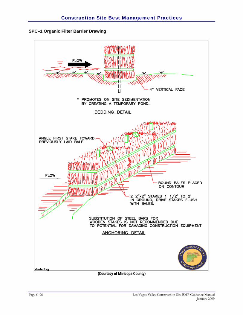
Construction Site Best Management Practices
Page C-96 Las Vegas Valley Construction Site BMP Guidance Manual January 2009
SPC–1 Organic Filter Barrier Drawing
(Courtesy of Maricopa County)
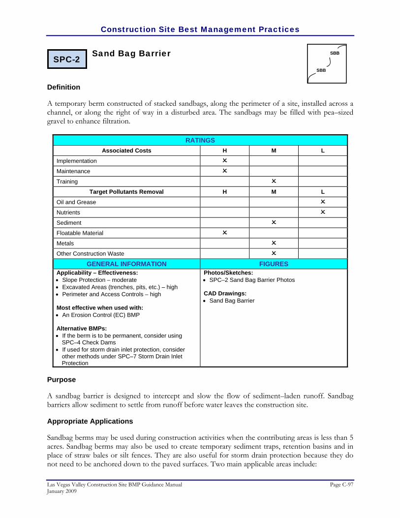
Construction Site Best Management Practices
Las Vegas Valley Construction Site BMP Guidance Manual Page C-97 January 2009
Sand Bag Barrier
Definition
A temporary berm constructed of stacked sandbags, along the perimeter of a site, installed across a channel, or along the right of way in a disturbed area. The sandbags may be filled with pea–sized gravel to enhance filtration.
RATINGS Associated Costs H M L
Implementation
Maintenance
Training
Target Pollutants Removal H M L
Oil and Grease
Nutrients
Sediment
Floatable Material
Metals
Other Construction Waste
GENERAL INFORMATION FIGURES Applicability – Effectiveness: • Slope Protection – moderate • Excavated Areas (trenches, pits, etc.) – high • Perimeter and Access Controls – high Most effective when used with: • An Erosion Control (EC) BMP Alternative BMPs: • If the berm is to be permanent, consider using
SPC–4 Check Dams • If used for storm drain inlet protection, consider
other methods under SPC–7 Storm Drain Inlet Protection
Photos/Sketches:• SPC–2 Sand Bag Barrier Photos CAD Drawings: • Sand Bag Barrier
Purpose
A sandbag barrier is designed to intercept and slow the flow of sediment–laden runoff. Sandbag barriers allow sediment to settle from runoff before water leaves the construction site.
Appropriate Applications
Sandbag berms may be used during construction activities when the contributing areas is less than 5 acres. Sandbag berms may also be used to create temporary sediment traps, retention basins and in place of straw bales or silt fences. They are also useful for storm drain protection because they do not need to be anchored down to the paved surfaces. Two main applicable areas include:
SPC-2 SBB
SBB

Construction Site Best Management Practices
Page C-98 Las Vegas Valley Construction Site BMP Guidance Manual January 2009
• Perimeter control:
• These areas include the entire construction site boundary, around stockpiles, along streams and channels, across channels to serve as a barrier for utility trenches, parallel to a roadway to keep sediment off paved areas, and along the perimeter of vehicle and equipment fuelling and maintenance areas or chemical storage areas.
• Furthermore, sand bag barriers are useful when site conditions or construction sequencing require adjustments or relocation of the barrier to meet changing field conditions and needs during construction, and to temporarily close or continue broken, damaged or incomplete curbs.
• Temporary diversion structure
• Sand bag barriers can be used as a temporary diversion structure below the toe of exposed and erodible slopes and down slope of exposed soil areas. They can also be used as a temporary sediment/desilting basin.
Limitations
• Limit the drainage area upstream of the barrier to 10 acres or less.
• Degraded sandbags may rupture when removed, spilling sand.
• Sandbag barrier installation can be labor intensive.
• Sandbag barriers have limited durability for long–term projects.
• When used to detain concentrated flows, maintenance requirements of sandbags increases.
Planning Considerations
Sandbag barriers are appropriate to use when construction of check dams in a channel is unnecessary. They can provide the same function as a check dam with less disturbance to the stream or vegetation. The sandbag barrier can also retain sediment prior to construction of final detention basins. For lower flows and paved surfaces, consider using rock socks (described below in Recommended Standards and Specifications). Small rock socks are easier to handle and cause less traffic problems than sand bags.
Recommended Standards and Specifications
• Materials:
• Sandbags: The bag should be made of woven polypropylene, polyethylene or polyamide fabric, minimum unit weight 4 ounces per square yard, mullen burst strength exceeding 300 psi in conformance with the requirements in ASTM designation D3786, and ultraviolet stability exceeding 70 percent in conformance with the requirements in ASTM designation D4355. Use of

Construction Site Best Management Practices
Las Vegas Valley Construction Site BMP Guidance Manual Page C-99 January 2009
burlap is not acceptable. Bag dimensions are nominal, and may vary based on locally available materials. Sand–filled bags generally are 24–30 inches long, 16–18 inches wide, 6–8 inches thick, and weigh approximately 90–125 pounds. The choice of fill material depends on the objectives that are desired from the sand bag barriers. If fine grained sand is used as fill material, the sand bag barrier will provide a barrier and act as a diversion dike. If coarser grained materials are used (i.e., pea–sized gravel), the barrier will allow flow to pass through and act more as a sediment filter.
• Rock socks: An alternative to sand bags are rock socks, which are more elongated than sand bags and contain pea–size rock. A rock sock should be made of a loosely woven material, such as burlap, when used for filtration. A tighter weave, such as a geotextile, is better for diversion. Note that burlap rock socks are not as sturdy as geotextile ones, but can be recycled on site since they quickly biodegrade.
• Installation: When used as a linear sediment control:
• Install along a level contour.
• Turn ends of sandbag row up slope to prevent flow around the ends.
• Generally, sandbag barriers should be used in conjunction with temporary soil stabilization controls up slope to provide effective erosion and sediment control.
• Sandbag barriers should be set back at least 3 feet from the toe of a slope where practical.
Recommended Maintenance and Inspection
• Inspect sandbag barriers before and after each rainfall event, and weekly otherwise.
• Reshape or replace sandbags as needed.
• Inspect sandbag barriers for sediment accumulations and remove sediments when accumulation reaches one–third the barrier height.
• Remove sandbags when no longer needed. Remove sediment accumulation, and clean, re–grade, and stabilize the area.

Construction Site Best Management Practices
Page C-100 Las Vegas Valley Construction Site BMP Guidance Manual January 2009
Post Construction Methods
None.
References
CALTRANS, State of California Department of Transportation, Construction Site Best Management Practices (BMPs) Manual, March 2003. http://www.dot.ca.gov/hq/construc/stormwater/manuals.htm
City of Tacoma, Surface Water Management Manual Volume II, Construction Stormwater Pollution Prevention,
Tacoma Public Works Environmental Services, January 1993. http://www.ci.tacoma.wa.us/waterservices/permits/Manual.htm
Environmental Protection Agency, Construction Site Storm Water Runoff Control, National Menu of Best
Management Practices for Storm Water Phase II, December 1999. http://cfpub2.epa.gov/npdes/stormwater/menuofbmps/con_site.cfm
Fifield, J.S., Field Manual on Sediment and Erosion Control, Forester Press, Santa Barbara CA, 2002. SMRC, Stormwater Manager’s Resource Center, Center for Watershed Protection, Inc.
http://www.stormwatercenter.net/
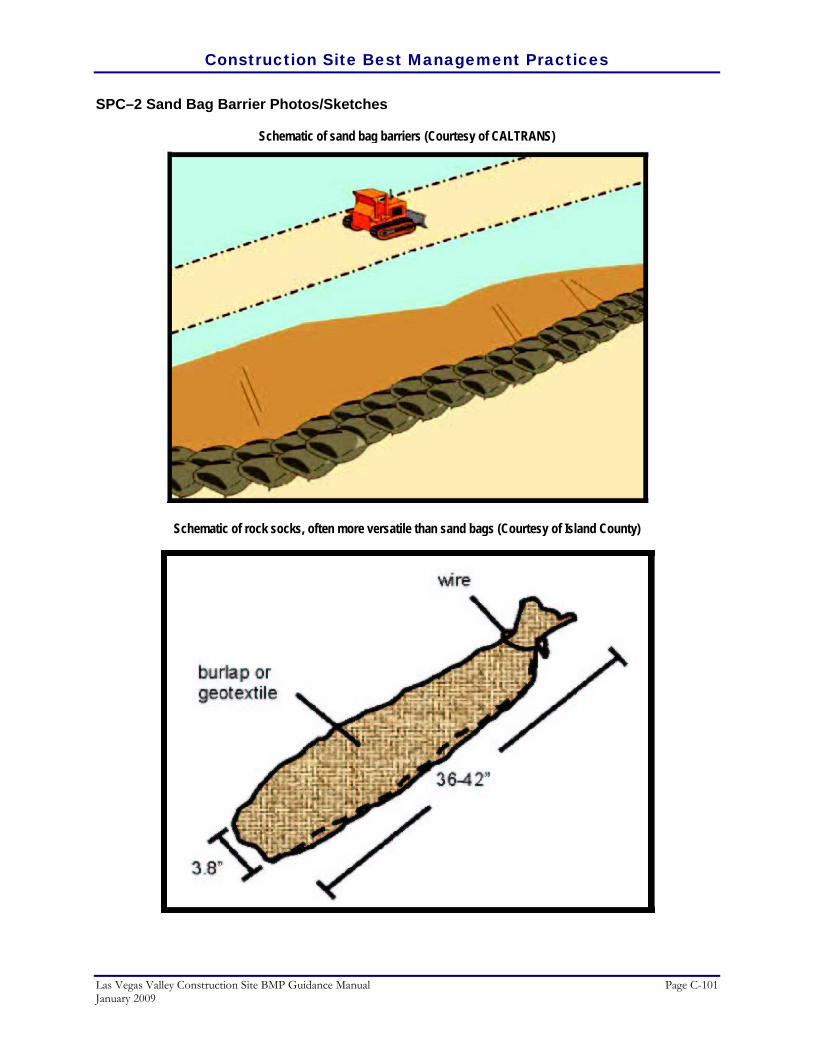
Construction Site Best Management Practices
Las Vegas Valley Construction Site BMP Guidance Manual Page C-101 January 2009
SPC–2 Sand Bag Barrier Photos/Sketches
Schematic of sand bag barriers (Courtesy of CALTRANS)
Schematic of rock socks, often more versatile than sand bags (Courtesy of Island County)

Construction Site Best Management Practices
Page C-102 Las Vegas Valley Construction Site BMP Guidance Manual January 2009
SPC–2 Sand Bag Barrier Drawing
(Courtesy of Maricopa County)

Construction Site Best Management Practices
Las Vegas Valley Construction Site BMP Guidance Manual Page C-103 January 2009
Gravel Filter Berms
Definition
A temporary berm constructed of open graded rock or bags of gravel installed at the toe of a slope, or the perimeter of a developing or disturbed area.
RATINGS Associated Costs H M L
Implementation
Maintenance
Training
Target Pollutants Removal H M L
Oil and Grease
Nutrients
Sediment
Floatable Material
Metals
Other Construction Waste
GENERAL INFORMATION FIGURES Applicability – Effectiveness: • Slope Protection – moderate • Excavated Areas (trenches, pits, etc.) – high • Perimeter and Access Controls – high Most effective when used with: • An Erosion Control (EC) BMP Alternative BMPs: • If the berm is to be permanent, consider using
SPC–4 Check Dams • If used for storm drain inlet protection, consider
other methods under SPC–7 Storm Drain Inlet Protection
Photos/Sketches:• SPC–3 Gravel Filter Berms Photos CAD Drawings: • Gravel Filter Berms
Purpose
Gravel filter berms are designed to intercept and detain sediment–laden water from an unprotected area, detain the sediment, and release the water in sheet flow.
Appropriate Applications
Where a temporary measure is needed to retain sediments such as:
• Near the toe of slopes.
• At construction site perimeters.
SPC-3 GFB
GFB

Construction Site Best Management Practices
Page C-104 Las Vegas Valley Construction Site BMP Guidance Manual January 2009
• May be used as check dams across one or more lanes of construction traffic temporary roads, or unsurfaced rights of way subject to construction traffic.
Limitations
• Limit the drainage area upstream of the barrier to 5 acres and to gently sloping areas.
• Not recommended to be built on landscaped areas due to the difficulty of clean up
• Gravel filter berms are only temporary and must be routinely maintained due to clogging from mud and soil on vehicle tires.
Planning Considerations
• Construct along a level contour for intercepting sheet flow.
• Provide an undisturbed or stabilized outlet suitable for sheet flow.
• Allow ample room for sediment removal equipment between the berm and toe–of–slope.
• Installation in stream beds requires large rock, staking of woven wire sheathing (gabions), and daily inspection.
• For a more vegetated control, consider Organic Filter Barriers. In order to lessen the chance of displaced material, consider Sand Bag Barriers, or Silt Fences. Gravel filter berms are more effective when combined with an erosion control BMP.
Recommended Standards and Specifications
Open Graded Rock: Open graded rock berms should be built on a level contour, designed for a maximum flow rate of 0.13 cubic feet per second (cfs) per square foot of berm. Use ¾- to 3-inch diameter rock for sheet flow and 3 to 5 inch diameter rock for concentrated flow. For non–traffic areas, open graded rock berms should be constructed a minimum of 18 inches high and 24 inches wide, with side slopes of 2:1 or flatter. Woven wire sheathing (poultry netting) is recommended in areas of concentrated flow to keep rocks in place. The wire should be galvanized 20 gauge with 1 inch diameter hexagonal mesh. Provide multiple berms in series:
• Every 300 feet on slopes less than 5 percent • Every 200 feet on slopes of 5-10 percent. • Every 100 feet on slopes greater than 10 percent.
If the open graded rock berm is constructed in a traffic area, the berm should be a maximum of 12 inches high.
Construction Site Best Management Practices
Las Vegas Valley Construction Site BMP Guidance Manual Page C-105 January 2009
Gravel Bag Berms: Gravel bags should be made of woven polypropylene, polyethylene, or polyamide fabric. Bags should have a minimum unit weight of four ounces per square yard, mullen burst strength exceeding 300 pounds per square inch (psi) in conformance with the requirements in ASTM designation D3786, and ultraviolet stability exceeding 70 percent in accordance with ASTM D4355. Bag dimensions are nominal and may vary based on locally available bags and fill material. Generally, gravel bags are 24–30 inches long, 16–18 inches wide, 68 inches thick, and weigh approximately 90–125 pounds. Alternative bag sizes should be submitted to the site supervisor or engineer for approval prior to installing at the site. The choice of fill material depends on the objectives that are desired from the gravel bag berm. If finer grained material is used (i.e., pea–sized gravel), the berm acts more as a sediment filter and allows a lower flow than if coarser grained gravel is used (i.e., ¾ to 3 inch diameter gravel). When used as a linear control for sediment removal:
• Install along a level contour.
• Turn the ends of the gravel bag berm up slope to prevent flow around the ends.
• Generally, gravel bag barriers should be used in conjunction with temporary soil stabilization controls up slope to provide effective erosion and sediment control.
When used for concentrated flows:
• Stack gravel bags to required height using a pyramid approach.
• Upper rows of gravel bags should overlap joints in lower rows.
• Construct gravel bag barriers with a set–back of at least 3 feet from the toe of a slope, or as far back as possible if the 3 foot set back is not physically possible.
Recommended Maintenance and Inspection
• Remove retained sediments when depth reaches 3 of berm height or 1 foot, whichever occurs first.
• Inspect monthly and after each rainfall. Reshape berm as needed, replace lost or dislodged rock.
• Remove gravel filter berm at the end of construction
Post Construction Methods
None.
References
CALTRANS, State of California Department of Transportation, Construction Site Best Management Practices (BMPs) Manual, March 2003. http://www.dot.ca.gov/hq/construc/stormwater/manuals.htm

Construction Site Best Management Practices
Page C-106 Las Vegas Valley Construction Site BMP Guidance Manual January 2009
City of Austin, Texas, March, Environmental Criteria Manual, 2004. Tacoma Public Works Environmental Services, City of Tacoma Surface Water Management Manual
Volume II, Construction Stormwater Pollution Prevention, January 1993. http://www.ci.tacoma.wa.us/waterservices/permits/Manual.htm
U. S. Environmental Protection Agency, Construction Site Storm Water Runoff Control, National Menu of
Best Management Practices for Storm Water Phase II, December 1999. http://cfpub2.epa.gov/npdes/stormwater/menuofbmps/con_site.cfm

Construction Site Best Management Practices
Las Vegas Valley Construction Site BMP Guidance Manual Page C-107 January 2009
SPC–3 Gravel Filter Berms Photos/Sketches
Gravel filter berms filter sediment–laden water for relatively high flows (Courtesy of Douglas County)

Construction Site Best Management Practices
Page C-108 Las Vegas Valley Construction Site BMP Guidance Manual January 2009
SPC–3 Gravel Filter Berms Drawing
(Courtesy of Douglas County)

Construction Site Best Management Practices
Las Vegas Valley Construction Site BMP Guidance Manual Page C-109 January 2009
Check Dams
Definition
Small barriers consisting of rock, sand bag, or earth berms placed across a drainage swale or ditch. Typically, they are used in conjunction with other channel protection techniques such as vegetation lining and turf reinforcement mats.
RATINGS Associated Costs H M L
Implementation
Maintenance
Training
Target Pollutants Removal H M L
Oil and Grease
Nutrients
Sediment
Floatable Material
Metals
Other Construction Waste
GENERAL INFORMATION FIGURES Applicability – Effectiveness: • Slope Protection – moderate • Excavated Areas (trenches, pits, etc.) – high • Perimeter and Access Controls – high • Channels and Medians – high Most effective when used with: • An Erosion Control (EC) BMP Alternative BMPs: • For a more temporary dam, consider SPC–2 Sand
Bag Barrier
Photos/Sketches:• SPC–4 Check Dams Photos CAD Drawings: • Check Dams Specifications
Purpose
Check dams reduce the velocity of small concentrated flows, provide a barrier for sediment, and help disperse concentrated flows, thereby reducing potential erosion.
Appropriate Applications
Check dams are appropriate where a temporary measure is needed to retain sediments such as:
• Near the toe of slopes.
• At construction site perimeters.
SPC-4 CD
CD

Construction Site Best Management Practices
Page C-110 Las Vegas Valley Construction Site BMP Guidance Manual January 2009
• May be used as check dams across one or more lanes of construction traffic temporary roads, or unsurfaced rights of way subject to construction traffic.
Limitations
• Check dams should not be used in live, flowing streams. They should not be used as a stand–alone substitute for other sediment trapping devices. Do not install check dams in channels, which have already been lined or vegetated. Leaves can clog check dams, thereby reducing their filtering and velocity dissipating functions.
• Check dams only perform their function of reducing velocities of concentrated flows and energy if they have been sized and constructed correctly and are maintained properly.
Planning Considerations
• Construct along a level contour for intercepting sheet flow.
• Provide an undisturbed or stabilized outlet suitable for sheet flow.
• Allow ample room for sediment removal equipment between the berm and toe–of–slope.
• Installation in stream beds requires large rock, staking of woven wire sheathing, and daily inspection.
Recommended Standards and Specifications
• Check dams should be installed as soon as construction will allow and be used in conjunction with other sediment reduction techniques prior to releasing the flow off-site.
• Check dams should be placed at a distance and height to allow small pools to form between each one. Typically, dam height should be between 18 and 36 inches. Dams should be spaced such that the top of the downstream dam is the same elevation as the toe of the upstream dam. Place check dams along the same contour line, perpendicular to the flow of water.
• Major flows (greater than 2 year design storm) must pass the check dam without causing excessive upstream flooding.
• Use geotextile filter fabric under check dams exceeding 18 inches in height.

Construction Site Best Management Practices
Las Vegas Valley Construction Site BMP Guidance Manual Page C-111 January 2009
Three main types of check dams:
• Rock Check Dam – usually the simplest and least expensive option.
• Stone should be well graded with a size range from 1.5 to 3.5 inches in diameter, depending on expected flows
• Rock check dams should be triangular in cross section with side slopes of 1:1 or flatter on the upstream side and 2:1 or flatter on the downstream side.
• Sand Bag Check Dam – are lighter and more manageable than rock dams.
• Sand bag check dams should have a maximum flow through rate of 0.1 cubic feet per second (cfs) per square foot of surface with a minimum top width of 16 inches and bottom width of 48 inches. Bags should be filled with clean coarse sand, pea gravel, or filter stone.
• Bag should be 24–30 inches long, 16–18 inches wide, 6–8 inches thick, and approximately 40 pounds in weight.
• Bag material should be polypropylene, polyethylene, polyamide, or cotton burlap woven fabric, minimum unit weight of four ounces per square yard, Mullen burst strength exceeding 300 pounds per square inch (psi) as determined by ASTM D3786.
• PVC pipes may be installed through the sand bag dam near the top to allow for controlled flow through the dam. Pipe should be schedule 40 or heavier, having a nominal internal diameter of 4 inches.
• Geotextile–Encased Check Dam (or Triangular Silt Dike) – may provide the most effective filtration of sediment laden water.
• Consist of a triangular urethane foam sewn into a woven geosynthetic fabric. Dimensions include 10–14 inches high in the center, with a 20–28 inch base. A 2 foot apron extends beyond both sides of the triangle along its standard section of 7 feet. A sleeve at one end of one section can be overlapped and stapled with an adjacent section.
• Install with ends curved up to prevent water from flowing around the ends.
• The fabric flaps and check dam units are attached to the ground with wire staples. Wire staples should be No. 11 gauge wire and should be 8 to 12 inches long.
• The leading edge must be secured with rocks, sandbags, or a small key slot and staples.
Construction Site Best Management Practices
Page C-112 Las Vegas Valley Construction Site BMP Guidance Manual January 2009
Recommended Maintenance and Inspection
• Check dams should be inspected after each storm event to ensure continued effectiveness. During inspection, large debris, trash, and leaves should be removed. The center of a check dam should always be slightly lower than its edges. If erosion or heavy flows cause the edges of a dam to fall to a height equal to or below the height of the center, repairs should be made immediately.
• Accumulated sediment should be removed from the upstream side of a check dam when the sediment has reached a height of approximately one–half the original height of the dam (measured at the center). In addition, all accumulated sediment should also be removed prior to removing a check dam.
• Removal of a check dam should be completed only after the contributing drainage area has been completely stabilized. Permanent vegetation and mulching should replace areas from where the check dam has been removed.
Post Construction Methods
None.
References
CALTRANS, State of California Department of Transportation, Construction Site Best Management Practices (BMPs) Manual, March 2003. http://www.dot.ca.gov/hq/construc/stormwater/manuals.htm
Kamber Engineering, Gaithersburg, Maryland, Sedimentation and Erosion Control, An Inventory of Current
Practices, USEPA, April, 1991. North Central Texas Council of Governments, Integrated Storm Water Management (iSWM) Design
Manual for Construction, December 2003. Tacoma Public Works Environmental Services, City of Tacoma Surface Water Management Manual
Volume II, Construction Stormwater Pollution Prevention, January 1993. http://www.ci.tacoma.wa.us/waterservices/permits/Manual.htm
U. S. Environmental Protection Agency, Construction Site Storm Water Runoff Control, National Menu of
Best Management Practices for Storm Water Phase II, December 1999. http://cfpub2.epa.gov/npdes/stormwater/menuofbmps/con_site.cfm
Washington Department of Ecology, Stormwater Management Manual for Western Washington,
Publications #99–11 through 99–15, August 2001.

Construction Site Best Management Practices
Las Vegas Valley Construction Site BMP Guidance Manual Page C-113 January 2009
SPC–4 Check Dams Photos/Sketches
Check dams can be constructed of crushed rock material from the construction project (Courtesy of Newfoundland)
Check dams are most effective when placed in series (Courtesy of NCDOT)

Construction Site Best Management Practices
Page C-114 Las Vegas Valley Construction Site BMP Guidance Manual January 2009
SPC–4 Check Dams Drawing
(Courtesy of Maricopa County)

Construction Site Best Management Practices
Las Vegas Valley Construction Site BMP Guidance Manual Page C-115 January 2009
Silt Fence
Definition
A geotextile fabric stretched between either wooden or metal posts with the lower edge of the fabric securely embedded in the soil. The fence is typically located downstream of disturbed areas to intercept sheet flow runoff.
RATINGS Associated Costs H M L
Implementation
Maintenance
Training
Target Pollutants Removal H M L
Oil and Grease
Nutrients
Sediment
Floatable Material
Metals
Other Construction Waste
GENERAL INFORMATION FIGURES Applicability – Effectiveness: • Slope Protection – moderate • Excavated Areas (trenches, pits, etc.) – high • Perimeter and Access Controls – high Most effective when used with: • An Erosion Control (EC) BMP Alternative BMPs: • EC–9 Diversion Dike • SPC–1 Organic Filter Barrier • SPC–2 Sand–Bag Barrier • SPC–3 Gravel Filter Berms • SPC–6 Revegetation • SPC–7 Storm Drain Inlet Protection
Photos/Sketches:• SPC–5 Silt Fence Photos CAD Drawings: • Silt Fence
Purpose
There are two main purposes for silt fences:
• To intercept and detain small amounts of sediment from disturbed areas during construction operations in order to prevent sediment from leaving the site.
• To decrease the velocity of sheet flows and low–to–moderate level channel flows.
SPC-5

Construction Site Best Management Practices
Page C-116 Las Vegas Valley Construction Site BMP Guidance Manual January 2009
Appropriate Applications
Silt fences, as the name implies, are more effective with sandy or silty soil types. For very fine grained soils, such as clays, a soils engineer should confirm the suitability of a silt fence for that area. Silt fences are generally applicable to construction sites with relatively small drainage areas. Silt fences are not intended for use in detaining concentrated flows. They are appropriate where runoff is a low–level shallow flow, not exceeding 0.5 cfs. The drainage area for silt fences generally should not exceed 0.25 acre per 100 feet of fence length. Slope length above the fence should not exceed 100 feet. Silt fences may be used:
• Below disturbed areas where runoff may occur in the form of sheet and rill erosion; wherever runoff has the potential to impact downstream resources.
• Parallel to minor swales or ditch lines for up to one acre of contributing drainage areas.
• For both site development areas and linear roadway type projects.
Limitations
• Silt fences are less effective in areas with predominately clay soil types.
• Silt fences will create a temporary sedimentation pond on the upstream side of the fence, which may cause temporary flooding.
• Silt fences are not practical for large flows. Drainage areas should be restricted to less than one acre and a flow rate less than 0.5 cfs. Do not allow water depth to exceed 1.5 feet at any point in front of the silt fence.
• Silt fences may not filter runoff effectively if the pore size of the fabric is incorrectly selected. Improperly installed fences are subject to failure from undercutting, overtopping, or collapsing.
Planning Considerations
If the site contains a high content of clays, consult a soils engineer before installing a silt fence. The Virginia Highway and Transportation Research Council has shown that silt fences can trap a much higher percentage of suspended sediments than straw bales can. Silt fences are preferable to straw barriers in many cases. However, while the failure rate of silt fences is lower than that of straw barriers, there are many instances in which silt fences have been improperly installed. The installation methods outlined here can improve performance.
• Anchor the site fence fabric below the ground surface sufficiently to prevent flow from undercutting the fence.
• Construct along a level contour.

Construction Site Best Management Practices
Las Vegas Valley Construction Site BMP Guidance Manual Page C-117 January 2009
• Silt fences should remain in place until the disturbed area is permanently stabilized.
• Provide sufficient room for sediment removal equipment between the silt fence and toes of slopes or other obstructions.
• The ends of the filter fence should be turned uphill to prevent stormwater from flowing around the fence.
• Provide an undisturbed or stabilized outlet suitable for sheet flow.
• Do not construct in live streams or intermittently flowing channels. As alternatives to silt fences, consider using the following: Diversion Dikes, Organic Filter Barrier, Gravel Filter Berms, Sand Bag Barriers, Revegetation, or Storm Drain Inlet Protection.
Recommended Standards and Specifications
Materials: Selection of a filter fabric is based on soil conditions at the construction site, which affect the equivalent opening size (EOS) fabric specification, and characteristics of the support fence, which affect the choice of tensile strength. The designer should specify a filter fabric that retains the soil found on the construction site yet will have openings large enough to permit drainage and prevent clogging. If 50 percent or less of the soil, by weight, passes through US Standard Sieve No. 200, select the EOS that will retain 85 percent of the soil, by weight. In addition, consider the following recommendations in the table below during the selection of the equivalent opening size: Fabric fences are supported with wire mesh, as recommended by the fabric manufacturer. Filter fabric material should contain ultraviolet ray inhibitors and stabilizers to provide a minimum of six months of expected usable life at a temperature range of 0 degrees F. to 120 degrees F.
US Standard Sieve No.
Sieve Hole Size, Inches Comments/EOS Recommendations
70 0.0083 The EOS should not be larger than the openings of US Sieve No. 70 100 0.0059 If there is direct discharge to a stream, lake or wetland, then the EOS
should not be greater than the openings of US Sieve No. 100 200 0.0029 If greater than 85% of the soil passes this sieve hole size by weight,
do not use silt fences. Most of the particles in such a soil would not be retained if the EOS was too large or they would clog the fabric quickly if the EOS was too small. Consider Temporary Sediment Basins as an alternative BMP.
Fabric fences are supported with wire mesh, as recommended by the fabric manufacturer. Filter fabric material should contain ultraviolet ray inhibitors and stabilizers to provide a minimum of six months of expected usable life at a temperature range of 0 F. to 120 F. Installation: The following drainage and topographical characteristics of the site should be considered before installing silt fences.
• Upstream drainage area limited to 1 acre or less when used alone or in combination with sediment basin in a larger site.

Construction Site Best Management Practices
Page C-118 Las Vegas Valley Construction Site BMP Guidance Manual January 2009
• Maximum slope steepness perpendicular to fence line is 1:1.
• Maximum sheet or overland flow path length to the fence is 100 feet.
• Silt fences are not intended for concentrated flows greater than 0.5 cfs. Filter fences are to be constructed, as described below, on a level contour to maximize the available ponding area and prevent concentration of flow against the fence.
• Posts should be spaced a maximum of 6 feet apart and driven securely into the ground a minimum of 30 inches.
• A trench should be excavated approximately 8 inches wide and 12 inches deep along the line of posts and upslope from the barrier.
• When standard strength filter fabric is used, a wire mesh support fence should be fastened securely to the upslope side of the posts using heavy–duty wire staples at least 1 inch long, tie wires or hog rings. The wire should extend into the trench a minimum of 4 inches.
• The standard strength filter fabric should be stapled or wired to the fence, and 20 inches of the fabric should extend into the trench. When extra–strength filter fabric and closer post spacing are used, the wire mesh support fence may be eliminated and the filter fabric stapled or wired directly to the posts.
• The use of joints should be avoided. When joints are necessary, filter cloth should be spliced together only at a support post, with a minimum 6–inch overlap and both ends securely fastened to the post.
• The trench should be backfilled with ¾–inch minimum diameter washed gravel or compacted native material.
Recommended Maintenance and Inspection
Silt fences should be inspected regularly and frequently as well as after each rainfall event to ensure that they are intact and that there are no gaps at the fence–ground interface or tears along the length of the fence. If gaps or tears are found, they should be repaired or the fabric should be replaced immediately. Accumulated sediments should be removed from the fence base when the sediment reaches one–third to one–half the height of the fence. Sediment removal should occur more frequently if accumulated sediment is creating noticeable strain on the fabric and there is the possibility of the fence failing from a sudden storm event. Silt fences should not be removed until the upslope area has been permanently stabilized. When the silt fence is removed, the accumulated sediment also should be removed.
Post Construction Methods
None.

Construction Site Best Management Practices
Las Vegas Valley Construction Site BMP Guidance Manual Page C-119 January 2009
References
CALTRANS, State of California Department of Transportation, Construction Site Best Management Practices (BMPs) Manual, March 2003. http://www.dot.ca.gov/hq/construc/stormwater/manuals.htm
City of Austin, Texas, March, Environmental Criteria Manual, 2004. Fifield, J.S., Field Manual on Sediment and Erosion Control, Forester Press, Santa Barbara CA, 2002. Kamber Engineering, Gaithersburg, Maryland, Sedimentation and Erosion Control, An Inventory of Current
Practices, USEPA, April, 1991. North Carolina Department of Transportation, Best Management Practices for Construction and
Maintenance Activities, Chapter 5.0 Operation Best Management, Practices, August 2003. http://www.doh.dot.state.nc.us/operations/BMP_manual/Center for Watershed
Protection, Inc., Stormwater Manager’s Resource Center (SMRC). http://www.stormwatercenter.net/
North Central Texas Council of Governments, Integrated Storm Water Management (iSWM) Design
Manual for Construction, December 2003. Tacoma Public Works Environmental Services, City of Tacoma Surface Water Management Manual
Volume II, Construction Stormwater Pollution Prevention, January 1993. http://www.ci.tacoma.wa.us/waterservices/permits/Manual.htm
U. S. Environmental Protection Agency, Construction Site Storm Water Runoff Control, National Menu of
Best Management Practices for Storm Water Phase II, December 1999. http://cfpub2.epa.gov/npdes/stormwater/menuofbmps/con_site.cfm
Washington Department of Ecology, Stormwater Management Manual for Western Washington,
Publications #99–11 through 99–15, August 2001.

Construction Site Best Management Practices
Page C-120 Las Vegas Valley Construction Site BMP Guidance Manual January 2009
SPC–5 Silt Fence Photos/Sketches
Silt fences can span the entire length of a construction site when installed properly (Courtesy of Maricopa County)

Construction Site Best Management Practices
Las Vegas Valley Construction Site BMP Guidance Manual Page C-121 January 2009
SPC–5 Silt Fence Drawing
(Courtesy of Maricopa County)

Construction Site Best Management Practices
Page C-122 Las Vegas Valley Construction Site BMP Guidance Manual January 2009
Revegetation and Landscaped Buffers
Definition
Revegetation consists of restoring an area of trees, shrubs and ground covers to a pre-development or sustainable condition. Landscaped buffers create a stabilized zone between a disturbed construction area and neighbouring areas, particularly natural water bodies.
RATINGS Associated Costs H M L
Implementation
Maintenance
Training
Target Pollutants Removal H M L
Oil and Grease
Nutrients
Sediment
Floatable Material
Metals
Other Construction Waste
GENERAL INFORMATION FIGURES Applicability – Effectiveness: • Slope Protection – high • Excavated Areas (trenches, pits, etc.) – high • Perimeter and Access Controls – high • Channels and Medians – high • Landscaping and Vegetation – high Most effective when used with: • An Erosion Control (EC) BMP Alternative BMPs: • EC–8 Temporary Access Waterway Crossing • SPC–1 Organic Filter Barrier • SPC–2 Sand–Bag Barrier • SPC–3 Gravel Filter Berms • SPC–4 Check Dams • SPC–5 Silt Fence • SPC–7 Storm Drain Inlet Protection
Photos/Sketches:• SPC–6 Revegetation Photos CAD Drawings: • None
Purpose
Revegetation and landscaped buffers can provide superior, low maintenance, long–term erosion protection, and can often result in a more stable and aesthetically pleasing development. Vegetation or xeriscaping stabilizes the soil and helps prevent erosion, decrease stormwater runoff, moderate temperature, provide buffers and screens, filter pollutants from the air, supply oxygen, and provide habitat for wildlife.
SPC-6 RVG
RVG

Construction Site Best Management Practices
Las Vegas Valley Construction Site BMP Guidance Manual Page C-123 January 2009
Appropriate Applications
Revegetation can be applied in any area that is able to support vegetation, but it is most effective and beneficial on floodplains, near wetlands, along streambanks, and on steep, unstable slopes. In Las Vegas Valley, native vegetation must be considered and xeriscape applications will be most common. Buffer strips are also effective in separating land use areas that are not compatible and in protecting wetlands or water bodies by displacing activities that might be potential sources of nonpoint source pollution. Trees, shrubs, ground covers, seeding, and xeriscape landscaping should be applied:
• On steep or rocky slopes • Along drainage swales and drainage dikes • Around sediment basins to provide nutrient removal • Where soil conservation is necessary (i.e., roughened slopes) • Where attractive landscaping cover is desirable • Where on-site dust control is necessary • To establish a wildlife habitat
Limitations
Construction activities can easily injure or kill vegetation unless adequate protective measures are taken. Direct contact by equipment is the most obvious problem, but damage can also occur by root stress due to filling, excavating, or compacting too close to trees and shrubs. See Protection of Trees and Vegetation in Construction Areas for ways to protect vegetation on the construction site.
Planning Considerations
• Plants and ground cover can be used on cut–and–fill slopes adjacent to paved areas of shopping centers, schools, industrial parks, or other non–residential projects. They will also help to control foot traffic.
• Trees, shrubs, or ground covers may be planted in residential areas, along rights–of–way, or easements to reduce maintenance and improve appearance.
• Native vegetation is compatible with surrounding desert habitat. Consult a local nursery for recommended plant species and growing tips.
Consult local landscape architects, nurseries and cooperative extension services for guidance on planning and selecting vegetation and xeriscape designs appropriate for the Las Vegas Valley climate.
Recommended Standards and Specifications
Materials: There are many different species of plants from which to choose, but care must be taken in their selections. It is essential to select planting materials suited to both the intended use and specific site characteristics. Vegetative plans must include close–growing plants or an adequate

Construction Site Best Management Practices
Page C-124 Las Vegas Valley Construction Site BMP Guidance Manual January 2009
mulch with all plantings of trees, shrubs, and ground covers. Consult with local landscape architects and nurseries for selections of appropriate plant and xeriscape materials.
Recommended Maintenance and Inspection
Specific maintenance requirements may be listed on landscape plans and specifications. General requirements include: Trees: Young trees should receive an inch of water each week for the first two years after planting. Transplanted trees should be fertilized on an annual basis. Shrubs: Proper pruning, watering, and application of fertilizer is necessary to maintain healthy and vigorous shrubs. A heavy layer of mulch reduces weeds and retains moisture. Ground Cover: Trim old growth as needed to improve the appearance of ground covers. Seeding: Seeded areas should be inspected for failure or limited growth. If vegetation fails to grow well and the soil has been sufficiently watered, test the soil for low pH or nutrient imbalances. On a typical disturbed site, full plant establishment usually requires refertilization in the second growing season. Soil tests will determine whether additional fertilizer should be added.
Post Construction Methods
In many cases, revegetation and landscaped areas can remain after the construction project has been completed to continue the same functions as described in this BMP. Include revegetated areas with the final site dress–up or landscaping plan. As with any final site landscaping, ongoing maintenance for vegetation including mowing, pruning, watering, fertilizing, and weed and pest control will be necessary after project completion.
References
Center for Watershed Protection, Inc., Stormwater Manager’s Resource Center (SMRC). http://www.stormwatercenter.net/
iSWM, Integrated Storm Water Management Design Manual for Construction, North Central Texas Council of Governments, December 2003. Smolen, M.D., North Carolina Erosion and Sediment Control Planning and Design Manual, North Carolina
Sediment Control Commission, et al., September 1988. Tacoma Public Works Environmental Services, City of Tacoma Surface Water Management Manual
Volume II, Construction Stormwater Pollution Prevention, January 1993. http://www.ci.tacoma.wa.us/waterservices/permits/Manual.htm
Virginia Department of Conservation and Recreation, Division of Soil and Water Conservation, Virginia Erosion and Sedimentation Control Handbook, Third Edition 1992.

Construction Site Best Management Practices
Las Vegas Valley Construction Site BMP Guidance Manual Page C-125 January 2009
U. S. Environmental Protection Agency, Construction Site Storm Water Runoff Control, National Menu of Best Management Practices for Storm Water Phase II, December 1999. http://cfpub2.epa.gov/npdes/stormwater/menuofbmps/con_site.cfm

Construction Site Best Management Practices
Page C-126 Las Vegas Valley Construction Site BMP Guidance Manual January 2009
SPC–6 Revegetation Photos/Sketches
Groundcover reduces the surface area of a site that is exposed to rainfall erosion (Courtesy of Maricopa County)

Construction Site Best Management Practices
Las Vegas Valley Construction Site BMP Guidance Manual Page C-127 January 2009
Storm Drain Inlet Protection
Definition
A variety of methods of intercepting sediment at low point inlets through the use of stone, filter fabric, inlet inserts, and other materials. This is normally located at the inlet, providing either detention or filtration to reduce sediment and floatable materials in stormwater.
RATINGS Associated Costs H M L
Implementation
Maintenance
Training
Target Pollutants Removal H M L
Oil and Grease
Nutrients
Sediment
Floatable Material
Metals
Other Construction Waste
GENERAL INFORMATION FIGURES In Las Vegas Valley, storm drain inlet protection is prohibited in public rights-of-way. This BMP is approved for use only for private development properties. Applicability – Effectiveness: • Inlet Drain Protection – high • Channels and Medians – high • Perimeter and Access Controls – high Most effective when used with: • An Erosion Control (EC) BMP Alternative BMPs: • SPC–1 Organic Filter Barrier • SPC–2 Sand–Bag Barrier • SPC–3 Gravel Filter Berms • SPC–5 Silt Fence
Photos/Sketches:• SPC–7 Storm Drain Inlet Protection Photos CAD Drawings: • Filter Fabric Fence Drop Inlet Filter • Curb Inlet Protection
Purpose
Storm drain inlet protection measures prevent soil and debris from site erosion from entering storm drain drop inlets and clogging them. Typically, these measures are temporary controls that are implemented prior to large–scale disturbance of the surrounding site. The early use of storm drains during project development significantly reduces the occurrence of future erosion problems. In Las Vegas Valley, storm drain inlet protection is prohibited on all public roadways and rights-of-way. Storm drain inlet protection methods are only approved for use on private development properties.
SPC-7
or

Construction Site Best Management Practices
Page C-128 Las Vegas Valley Construction Site BMP Guidance Manual January 2009
Appropriate Applications
Storm drain inlet protection is appropriate where storm drain inlets are to be made operational before permanent stabilization of the disturbed drainage area. There are a variety of types of structures that are applicable to different conditions:
• Filter Fabric Fence – applicable where the inlet drains a relatively small (less than 1 acre) flat area (less than 5 percent slope). Intended for relatively low flows.
• Excavated Drop Inlet Sediment Trap – intended for relatively high flows. An excavated drop inlet trap provides protections against sediment entering a storm drain inlet can be provided by excavating an area in the approach to the drain. The excavation volume should be approximately 1800 to 3600 cubic feet per acre of disturbed area drained.
• Block and Gravel Protection – used when the flows exceed 0.5 cubic feet per second (cfs) and it is necessary to allow for overtopping to prevent flooding around the inlet area.
• Foam or Fiber Roll Barriers – use for relatively low flows in areas where they can be anchored to the surface. Most appropriate for inlets on an unpaved surface.
• Sand or Gravel Bags – use for relatively low flows.
Limitations
• Installing inlet protection on publicly travelled streets or in developed areas is prohibited by Las Vegas Valley entities. Drain inlets in public rights-of-way should be protected by using BMPs at the construction site boundary to prevent pollutant runoff.
• Inlet protection is only viable at low point inlets. Inlets that are on slope can not be effectively protected because stormwater will bypass the inlet and continue downstream, causing an overload on downstream inlets.
• Ponding will occur at the inlet with possible short term flooding.
• Curb inlets on slopes cannot be effectively protected because the stormwater will bypass the inlet and continue downgrade.
• Filter fabric fences are limited to storm drain inlets for small drainage areas of five acres or less. Filter fabric fences are not appropriate in paved areas. For larger drainage areas, smaller sediment catchment areas are recommended.

Construction Site Best Management Practices
Las Vegas Valley Construction Site BMP Guidance Manual Page C-129 January 2009
Planning Considerations
Where storm sewers are made operational before their drainage area is stabilized, or where construction is adjacent to an existing storm sewer, large amounts of sediment may enter the storm sewer system. In cases of extreme sediment loading, the storm sewer itself may clog and lose a major portion of its capacity. To avoid these problems, it is necessary to prevent sediment from entering the system at the inlets. This practice contains several types of inlet filters and traps which have different applications dependent upon site conditions and type of inlet. Other innovative techniques for accomplishing the same purpose are encouraged, but only after specific plans and details are submitted to and approved by the local government.
Recommended Standards and Specifications
Install inlet protection in accordance with the following:
• Filter fabric fence: Place 2 inch by 2 inch wooden stakes around the perimeter of the inlet a maximum of 3 feet apart and drive them at least 8 inches into the ground. Excavate a trench approximately 8 inches wide and 12 inches deep around the outside perimeter of the stakes. Staple the filter fabric (for material specifications, see Silt Fence to wooden stakes so that 32 inches of the fabric extends out and can be formed into the trench. Use heavy–duty wire staples at least ½ inch in length. Backfill the entire trench with ¾ inch or less washed gravel.
• Excavated Drop Inlet Sediment Trap: Construct the inlet trap as shown in the CAD drawing. Ensure that the excavation volume can contain approximately 1800 to 3600 cubic feet per acre of disturbed area.
• Gravel Bag Filter: If there is a high content of clays and silts, use filter fabric in conjunction with gravel for additional filtering capacity. Construct the gravel bag filter as specified by Gravel Filter Berms.
• Foam or Fiber Roll Barrier: Foam or fiber roll is placed around the inlet and must be anchored to the curb surface, so that it is not carried away by runoff flows.
Recommended Maintenance and Inspection
For systems using filter fabric, inspections should be made on a regular basis, especially after large storm events. If the fabric becomes clogged, it should be replaced. Sediment should be removed when it reaches approximately half the height of the fence. If an excavated inlet sediment trap is used, sediment should be removed when it fills approximately half the depth of the hole.

Construction Site Best Management Practices
Page C-130 Las Vegas Valley Construction Site BMP Guidance Manual January 2009
Post Construction Methods
Following the completion of construction projects in residential and municipal areas, more permanent drop–inlet protection devices can be installed in storm drain inlets.
References
CALTRANS, State of California Department of Transportation, Construction Site Best Management Practices (BMPs) Manual, March 2003. http://www.dot.ca.gov/hq/construc/stormwater/manuals.htm
Center for Watershed Protection, Inc., Stormwater Manager’s Resource Center (SMRC).
http://www.stormwatercenter.net/ Goldman, S.J., Jackson, K., and Bursztynsky, T.A., Erosion and Sediment Control Handbook, McGraw
Hill Book Company, 1986. Kamber Engineering, Gaithersburg, Maryland, Sedimentation and Erosion Control, An Inventory of Current
Practices, USEPA, April, 1991. North Carolina State University, (NCSU) North Carolina Nonpoint Source Pollution Control Measures.
http://h2osparc.wq.ncsu.edu/info/bmps.html North Central Texas Council of Governments, Integrated Storm Water Management (iSWM) Design
Manual for Construction, December 2003. Smolen, M.D., North Carolina Erosion and Sediment Control Planning and Design Manual, North Carolina
Sediment Control Commission, et al, September 1988. Tacoma Public Works Environmental Services, City of Tacoma Surface Water Management Manual
Volume II, Construction Stormwater Pollution Prevention, January 1993. http://www.ci.tacoma.wa.us/waterservices/permits/Manual.htm
U. S. Environmental Protection Agency, Construction Site Storm Water Runoff Control, National Menu of
Best Management Practices for Storm Water Phase II, December 1999. http://cfpub2.epa.gov/npdes/stormwater/menuofbmps/con_site.cfm
Urban Drainage and Flood Control District, Construction BMPs Chapter of Urban Storm Drainage Criteria
Manual, Vol. 3: Best Management Practices, Denver, Colorado, 1999. Washington Department of Ecology, Stormwater Management Manual for Western Washington,
Publications #99–11 through 99–15, August 2001.

Construction Site Best Management Practices
Las Vegas Valley Construction Site BMP Guidance Manual Page C-131 January 2009
SPC–7 Storm Drain Inlet Protection Photos/Sketches
Coarse gravel and cinder blocks are often used to keep sediment and other pollutants out of storm drains (Courtesy of EPA)
Straw wattle inlet drain protection (Courtesy of Douglas County)

Construction Site Best Management Practices
Page C-132 Las Vegas Valley Construction Site BMP Guidance Manual January 2009
SPC–7 Storm Drain Inlet Protection Drawing
(Courtesy of Maricopa County)

Construction Site Best Management Practices
Las Vegas Valley Construction Site BMP Guidance Manual Page C-133 January 2009
(Courtesy of Maricopa County)

Construction Site Best Management Practices
Page C-134 Las Vegas Valley Construction Site BMP Guidance Manual January 2009
Temporary Sediment Basins
Definition
A pond area formed by constructing an embankment of compacted soil across a drainageway with a controlled outlet in which sedimentary laden runoff is directed to allow settling of suspended sediment from the runoff.
RATINGS Associated Costs H M L
Implementation
Maintenance
Training
Target Pollutants Removal H M L
Oil and Grease
Nutrients
Sediment
Floatable Material
Metals
Other Construction Waste
GENERAL INFORMATION FIGURES Applicability – Effectiveness: • Slope Protection – high • Excavated Areas (trenches, pits, etc.) – high • Perimeter and Access Controls – high • Landscaping and Vegetation – high Most effective when used with: • An Erosion Control (EC) BMP Alternative BMPs: • To treat lower flows and volumes than described in
this BMP, consider SPC–9 Temporary Sediment Traps
Photos/Sketches:• SPC–8 Temporary Sediment Basins Photos CAD Drawings: • Temporary Sediment Basins
Purpose
To collect and store sediment from sites cleared and/or graded during construction or for extended periods of time before reestablishment of permanent vegetation and/or construction of structures. It is intended to help treat and control silt–laden runoff. The basin is a temporary measure (with a design life less than 1 year) and is to be maintained until the site area is permanently protected against erosion or a permanent detention basin is constructed. Appropriate Applications
Sediment basins serve as treatment devices which can be used on a variety of project types. They are normally used in construction projects where:
SPC-8

Construction Site Best Management Practices
Las Vegas Valley Construction Site BMP Guidance Manual Page C-135 January 2009
• Large areas of land drain to the basin • A minor stream or off–line drainage way crosses the site • A specific water feature is planned for the site • Disturbed areas are greater than 5 acres during the rainy season • Sediment–laden water may enter the drainage system
Limitations
Sediment basins and ponds must be installed only within the property limits where failure of the structure would not result in loss of life, damage to homes or buildings, or interruption of use or service of public roads or utilities. Also, sediment basins and ponds are attractive to children and can be very dangerous. Local ordinances regarding health and safety must be adhered to. If fencing of the pond is required, the type of fence and its location should be shown on the Stormwater Pollution Prevention Plan (SWPPP).
• Generally, temporary sedimentation basins are for disturbed upstream drainage areas of 5 acres or more.
• Because of additional detention time, sediment basins may be capable of trapping smaller sediment particles than traps. However, they are most effective when used in conjunction with other BMPs such as seeding or mulching.
• Sediment basins may become attractive to children and care must be taken to adhere to all safety practices. Also, standing water can attract mosquitoes.
• Sediment basins are only practically effective in removing sediment down to about the medium silt size fraction. Sediment–laden runoff with smaller size fractions (fine silt and clay) will pass through untreated. This emphasizes the need to control erosion to the maximum extent first, rather than relying on sediment basins alone.
Planning Considerations
• Effectiveness:
• Sediment basins are at best only 70–80 percent effective in trapping sediment which flows into them. Therefore, they should be used in conjunction with erosion control practices such as temporary seeding, mulching, diversion dikes, etc. to reduce the amount of sediment flowing into the basin.
• Whenever possible, construct the sedimentation basins before clearing and grading work begins.
• Location:
• To improve the effectiveness of the basin, it should be located so as to intercept the largest possible amount of runoff from the disturbed area. The best locations are generally low areas below disturbed areas. Drainage into

Construction Site Best Management Practices
Page C-136 Las Vegas Valley Construction Site BMP Guidance Manual January 2009
the basin can be improved by the use of diversion dikes and ditches. The basin must not be located in a stream but should be located to trap sediment–laden runoff before it enters the stream. The basin should not be located where its failure would result in the loss of life or interruption of the use or service of public utilities or roads. The sediment basin should be located more than 25 feet from septic system facilities.
Recommended Standards and Specifications
The sediment basin may be formed by partial excavation and/or by construction of a compacted embankment. It may have one or more inflow points carrying polluted runoff. A securely anchored riser pipe is the principal discharge mechanism along with an emergency overflow spillway. The riser pipe should be solid with two 1–inch diameter dewatering holes located at the top of the sediment storage volume on opposite sides of the riser pipe as shown in the CAD file. Outlet protection is provided to reduce erosion at the pipe outlet.
• As a general guideline, the sediment basin volume should be designed for 2,000 cubic feet, assuming limited infiltration.
• A hydraulics engineer should be consulted to properly design a sediment basin. Refer to the CCRFCD Hydrologic Criteria and Drainage Design Manual for detailed design guidance. Total sediment pond volume and dimensions are determined as outlined below:
• Determine pond geometry for the storage volume calculated above using 3 feet in depth and 3:1 side slopes from the bottom of the basin. Note, the basin bottom is level.
• Adjust the geometry of the basin to effectively combine the settling zone volume and sediment storage volumes while preserving the depth and side slope criteria.
• Provide an emergency spillway with a crest elevation 1 foot above the top of the riser pipe.
• A minimum 3:1 length to width ratio is necessary. A larger length to width ratio (6:1) is even more effective to prevent short–circuiting. Baffles may also be implemented.
Maintenance and Inspection
• Inspect sediment basins before and after rainfall events or exceptionally large storms.
• Examine basin banks for seepage and structural soundness.
• Check inlet and outlet structures and spillway for any damage, obstructions, or erosion.

Construction Site Best Management Practices
Las Vegas Valley Construction Site BMP Guidance Manual Page C-137 January 2009
• Sediment basins should be drained within 36 hours after a rain event.
• Remove accumulated sediment when its volume reaches one–third the volume of the sediment storage. Properly dispose of sediment and debris removed from the basin, within the construction site.
• Check fencing for damage and repair.
Post Construction Methods
Sediment basins can be converted to permanent structures after completion of the construction project. Remove all excess sediment from the basin. The containment volume of permanent sediment basins will need to be expanded to meet the design storm requirements in the CCRFCD Hydrologic Criteria and Drainage Design Manual. The inside of a permanent sediment basin should either be vegetated or rock lined. Alternatively, if the permeability of the soil is high and groundwater is close to the ground surface, a clay or synthetic liner may be installed. Ensure that the sedimentation basin has a stabilized outlet (see Outlet Protection, Velocity Dissipation Devices).
References
CALTRANS, State of California Department of Transportation, Construction Site Best Management Practices (BMPs) Manual, March 2003. http://www.dot.ca.gov/hq/construc/stormwater/manuals.htm
Clark County Regional Flood Control District, Hydrologic Criteria and Drainage Design Manual,
August 1999. Goldman, S.J., Jackson, K., and Bursztynsky, T.A., Erosion and Sediment Control Handbook, McGraw
Hill Book Company, 1986. Kamber Engineering, Gaithersburg, Maryland, Sedimentation and Erosion Control, An Inventory of Current
Practices, USEPA, April, 1991. North Central Texas Council of Governments, Integrated Storm Water Management (iSWM) Design
Manual for Construction. Center for Watershed Protection, Inc., Stormwater Manager’s Resource Center (SMRC), December 2003.
http://www.stormwatercenter.net/ Tacoma Public Works Environmental Services, City of Tacoma Surface Water Management Manual
Volume II, Construction Stormwater Pollution Prevention, January 1993. http://www.ci.tacoma.wa.us/waterservices/permits/Manual.htm
U.S. Environmental Protection Agency, Construction Site Storm Water Runoff Control, National Menu of
Best Management Practices for Storm Water Phase II, December 1999. http://cfpub2.epa.gov/npdes/stormwater/menuofbmps/con_site.cfm
Washington Department of Ecology, Stormwater Management Manual for Western Washington,
Publications #99–11 through 99–15, August 2001.

Construction Site Best Management Practices
Page C-138 Las Vegas Valley Construction Site BMP Guidance Manual January 2009
SPC–8 Temporary Sediment Basins Photos/Sketches
Temporary sediment basin with outlet protection (Courtesy of Maricopa County)
Temporary sediment basins provide stormwater storage during the construction process (Courtesy of Maricopa County)

Construction Site Best Management Practices
Las Vegas Valley Construction Site BMP Guidance Manual Page C-139 January 2009
SPC–8 Temporary Sediment Basins Drawing
(Courtesy of Caltrans)
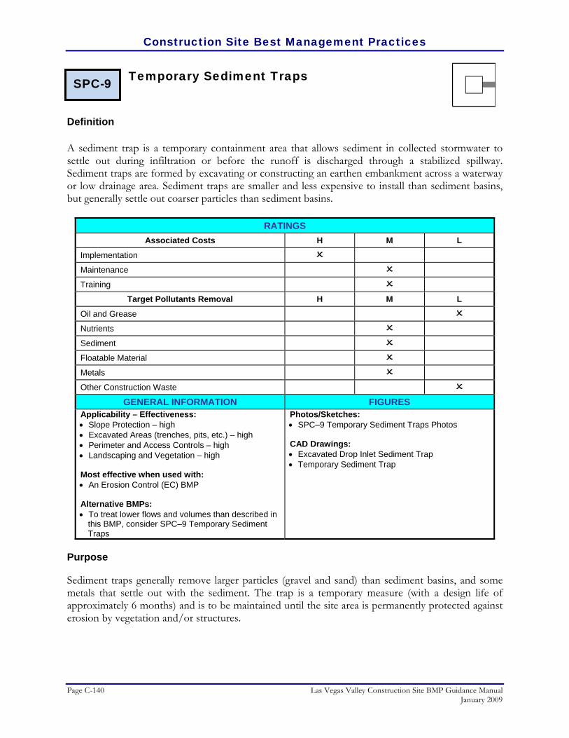
Construction Site Best Management Practices
Page C-140 Las Vegas Valley Construction Site BMP Guidance Manual January 2009
Temporary Sediment Traps
Definition A sediment trap is a temporary containment area that allows sediment in collected stormwater to settle out during infiltration or before the runoff is discharged through a stabilized spillway. Sediment traps are formed by excavating or constructing an earthen embankment across a waterway or low drainage area. Sediment traps are smaller and less expensive to install than sediment basins, but generally settle out coarser particles than sediment basins.
RATINGS Associated Costs H M L
Implementation
Maintenance
Training
Target Pollutants Removal H M L
Oil and Grease
Nutrients
Sediment
Floatable Material
Metals
Other Construction Waste
GENERAL INFORMATION FIGURES Applicability – Effectiveness: • Slope Protection – high • Excavated Areas (trenches, pits, etc.) – high • Perimeter and Access Controls – high • Landscaping and Vegetation – high Most effective when used with: • An Erosion Control (EC) BMP Alternative BMPs: • To treat lower flows and volumes than described in
this BMP, consider SPC–9 Temporary Sediment Traps
Photos/Sketches:• SPC–9 Temporary Sediment Traps Photos CAD Drawings: • Excavated Drop Inlet Sediment Trap • Temporary Sediment Trap
Purpose
Sediment traps generally remove larger particles (gravel and sand) than sediment basins, and some metals that settle out with the sediment. The trap is a temporary measure (with a design life of approximately 6 months) and is to be maintained until the site area is permanently protected against erosion by vegetation and/or structures.
SPC-9

Construction Site Best Management Practices
Las Vegas Valley Construction Site BMP Guidance Manual Page C-141 January 2009
Appropriate Applications
Sediment traps are generally temporary control measures to slow concentrated runoff velocity and catch sediment, and they can be used with other temporary stormwater control measures. Traps should be placed where sediment laden stormwater enters a storm drain or watercourse. They are commonly used at the outlets of stormwater diversion structures, channels, slope drains, construction site entrance wash racks, or any other runoff conveyance that discharges waters containing erosion sediment and debris. Sediment traps can also be used as part of a stormwater drop intake protection system when the inlet is located below a disturbed area and will receive runoff with large amounts of sediment. Sediment traps may be used on construction projects where the drainage area is less than 5 acres.
Limitations
• Requires large surface areas to permit infiltration and settling of sediment.
• Not appropriate for drainage areas greater than 5 acres.
• Only removes large and medium sized particles and requires upstream erosion control.
• Attractive and dangerous to children, and requires protective fencing.
• Not to be located in live streams.
• Size may be limited by availability of right–of–way.
Planning Considerations
Sediment traps should be used only for small drainage areas. If the contributing drainage area is greater than 5 acres, refer to SPC–8 Temporary Sediment Basins, or subdivide the catchment area into smaller drainage basins. Sediment must be removed from the trap after each significant rainfall event. Plans should detail how this sediment is to be disposed of, either using in–fill areas on-site or removal to an approved off-site dump. Sediment traps, along with other perimeter controls, should be installed before any land disturbance takes place in the drainage area. Sediment traps and ponds must be installed only on sites where failure of the structure would not result in loss of life, damage to home or buildings, or interruption of use of service public roads or utilities. Also, sediment traps are attractive to children and can be dangerous. The following recommendations should be implemented to reduce risks:
• Install continuous fencing around the sediment trap. Consult local ordinances regarding requirements for maintaining health and safety.
• Restrict sediment trap side slopes to 3:1 or flatter.

Construction Site Best Management Practices
Page C-142 Las Vegas Valley Construction Site BMP Guidance Manual January 2009
Recommended Standards and Specifications
• The sediment trap may be formed completely by excavation or by construction of a compacted embankment. The outlet should be a weir/spillway section, with the area below the weir acting as a filter for sediment and the upper area as the overflow spillway depth.
• The effectiveness of sediment traps is directly related to the size of the trap. As a general guideline, based on soil and slope characteristics, the recommended sediment trap volume is approximately 2,000 cubic feet per acre of disturbed upstream drainage area for drainage areas of 5 acres or less. The required volume can be reduced if additional erosion and/or sediment control practices have been implemented upstream of the sediment trap.
• After determining the necessary volume, size the trap by adding an additional 1.5 feet for sediment accumulation to the volume computed.
Recommended Maintenance and Inspection
Inspect sediment traps before and after rainfall events and weekly during the rest of the rainy season. During extended rainfall events, inspect sediment traps on a more frequent basis. The key to a functional sediment trap is continual monitoring and regular maintenance. If captured runoff has not completely drained within 36 hours. Then the sediment trap must be dewatered.
• Inspect trap banks for embankment seepage and structural soundness.
• Inspect outlet structure and rock spillway for any damage or obstructions. Repair damage and remove obstructions as needed. Inspect outlet area for erosion and stabilize if required.
• Remove accumulated sediment when the volume has reached one–third the original trap volume.
• Inspect fencing for damage and repair as needed.
Post Construction Methods
None.
References
CALTRANS, State of California Department of Transportation, Construction Site Best Management Practices (BMPs) Manual, March 2003. http://www.dot.ca.gov/hq/construc/stormwater/manuals.htm
Center for Watershed Protection, Inc., Stormwater Manager’s Resource Center (SMRC).
http://www.stormwatercenter.net/
Construction Site Best Management Practices
Las Vegas Valley Construction Site BMP Guidance Manual Page C-143 January 2009
City of Austin, Texas, March, Environmental Criteria Manual, 2004. North Central Texas Council of Governments, Integrated Storm Water Management (iSWM) Design
Manual for Construction, December 2003. Kamber Engineering, Gaithersburg, Maryland, Sedimentation and Erosion Control, An Inventory of Current
Practices, USEPA, April, 1991. U. S. Environmental Protection Agency, Construction Site Storm Water Runoff Control, National Menu of
Best Management Practices for Storm Water Phase II, December 1999. http://cfpub2.epa.gov/npdes/stormwater/menuofbmps/con_site.cfm
Washington Department of Ecology, Stormwater Management Manual for Western Washington,
Publications #99–11 through 99–15, August 2001.

Construction Site Best Management Practices
Page C-144 Las Vegas Valley Construction Site BMP Guidance Manual January 2009
SPC–9 Temporary Sediment Traps Photos/Sketches
Schematic of sediment trap and outlet protection (Courtesy of CALTRANS)
Sediment traps are used to collect sediment laden runoff from disturbed areas on construction sites (Courtesy of Douglas County)

Construction Site Best Management Practices
Las Vegas Valley Construction Site BMP Guidance Manual Page C-145 January 2009
SPC–9 Temporary Sediment Traps Drawing
(Courtesy of Maricopa County)

Construction Site Best Management Practices
Page C-146 Las Vegas Valley Construction Site BMP Guidance Manual January 2009
(Courtesy of Maricopa County)

Construction Site Best Management Practices
Las Vegas Valley Construction Site BMP Guidance Manual Page C-147 January 2009
Sediment Dewatering Operations
Definition A filtration bag or sediment bag is a large bag made of geotextile that is used for filtering water pumped as part of dewatering a worksite. The bag is hooked up to a hose and water is pumped through the bag. The water seeps through the geotextile fabric and the sediment is trapped in the bag.
RATINGS Associated Costs H M L
Implementation
Maintenance
Training
Target Pollutants Removal H M L
Oil and Grease
Nutrients
Sediment
Floatable Material
Metals
Other Construction Waste
GENERAL INFORMATION FIGURES Applicability – Effectiveness: • Slope Protection – moderate • Excavated Areas (trenches, pits, etc.) – high • Perimeter and Access Controls – high Most effective when used with: • Protect excavated areas before runoff enters by
using: • SPC–1 Organic Filter Barrier • SPC–2 Sand Bag Barrier • SPC–3 Gravel Filter Berms • For flows or sediment loads too large for a
dewatering treatment device, consider: • SPC–9 Temporary Sediment Traps Alternative BMPs: • For more efficient removal, use with: • SPC–8 Temporary Sediment Basins • SPC–9 Temporary Sediment Traps
Photos/Sketches:• SPC–10 Sediment Dewatering Operations Photos CAD Drawings: • None
Purpose
After storm events, dewatering of non–stormwater and accumulated rainfall from excavated work areas is often necessary before work can proceed. In the process of removing stormwater, certain measures must be taken to correctly discharge it.
SPC-10

Construction Site Best Management Practices
Page C-148 Las Vegas Valley Construction Site BMP Guidance Manual January 2009
Appropriate Applications
Dewatering is often implemented for discharges of non–stormwater from excavated work areas such as utility repairs and construction sites. Non–stormwater includes groundwater, water from cofferdams, water diversions, and water from drilling and other construction operations. Dewatering is also appropriate for removal of accumulated precipitation from depressed areas on a construction site.
Limitations
Dewatering controls described in this BMP are intended for control of sediment particles. Other control methods (i.e., sediment basins and sediment traps) may allow for longer settling time of sediment particles, and thus greater efficiency of removal, than dewatering controls. Dewatering discharges can be avoided by using the water for dust control or diverting it to an infiltration basin. Specific limitations for sediment filter bags include:
• Filtration bags full of sediment are heavy and may need to be lifted with a front–end loader.
• As bags fill up with sediment, they become clogged and may “explode” from force of pump if not removed in time.
• Sediment filter bags may not work with very fine particulates.
Planning Considerations
Before starting a dewatering operation, one or more of the following mechanisms must be in place to treat water during dewatering operations:
• Sediment basin • Sediment trap • Weir tanks • Dewatering tanks • Gravity bag filter
Alternatively, excavated areas can be protected before runoff enters by using: Organic Filter Barrier, Sand Bag Barrier, or Gravel Filter Berms.
Recommended Standards and Specifications
• Gravity bag filter: A gravity bag filter, also referred to as a dewatering bag, is a rectangular bag made of non–woven geotextile fabric for effective removal of sediments (gravel, sand, and silt). Some metals are removed with the sediment. Depending on size, the bag can handle up to 1500 gallons per minute. The bag should be installed on a slight slope so that water flows through the length of the bag. Place straps underneath the bag so that when full, the bag may be more easily lifted. Insert the hose (up to 4 inches in diameter) into the neck of the

Construction Site Best Management Practices
Las Vegas Valley Construction Site BMP Guidance Manual Page C-149 January 2009
dirtbag. Tie off the neck with baling wire and/or duct tape. Filtration bags come in sizes up to 15 feet by 15 feet. When filled with trapped sediment, it requires heavy equipment or a crew of men to lift it.
Recommended Maintenance and Inspection
Soil from full dewatering bags can either be reapplied to the site as it often contains nutrient rich top soil or should be properly disposed of off-site.
Post Construction Methods
None.
References
CALTRANS, State of California Department of Transportation, Construction Site Best Management Practices (BMPs) Manual, March 2003.
http://www.dot.ca.gov/hq/construc/stormwater/manuals.htm
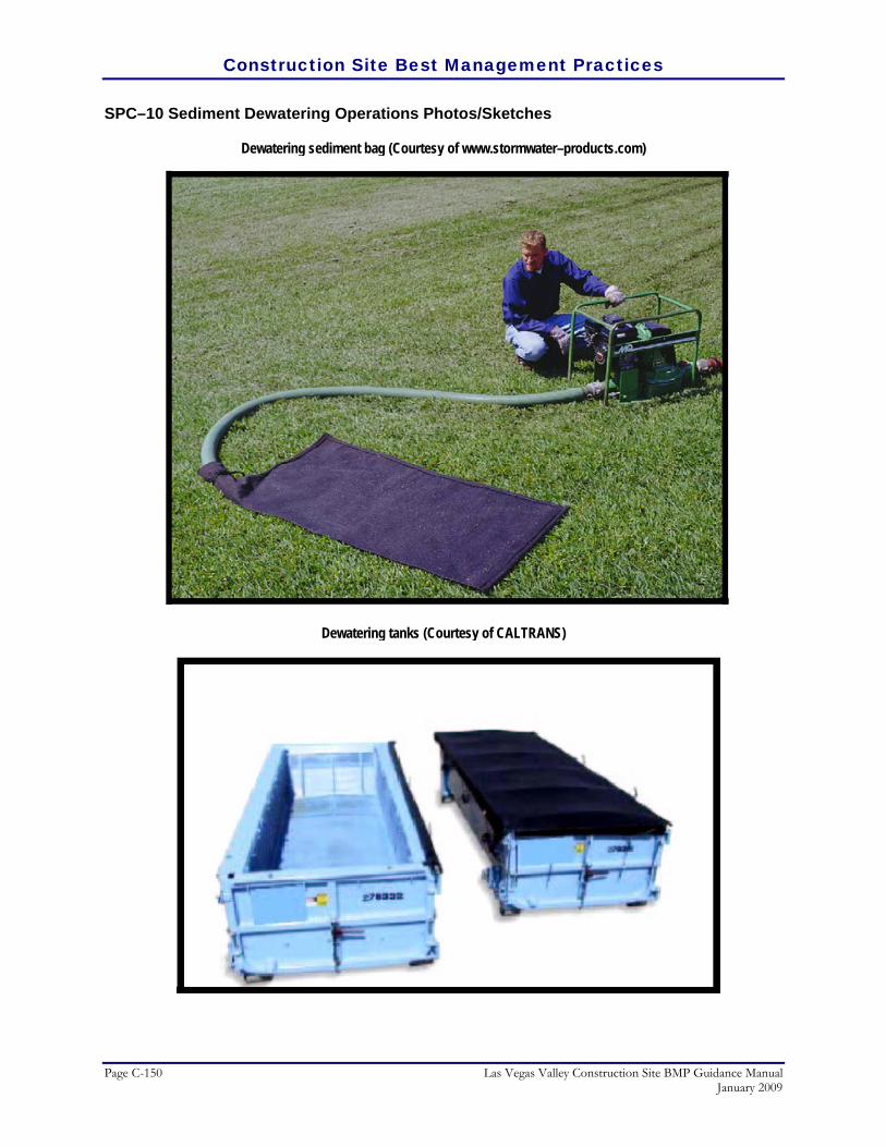
Construction Site Best Management Practices
Page C-150 Las Vegas Valley Construction Site BMP Guidance Manual January 2009
SPC–10 Sediment Dewatering Operations Photos/Sketches
Dewatering sediment bag (Courtesy of www.stormwater–products.com)
Dewatering tanks (Courtesy of CALTRANS)

Construction Site Best Management Practices
Las Vegas Valley Construction Site BMP Guidance Manual Page C-151 January 2009
Construction Entrance/Exit Tire Wash
Definition A tire wash is an area located at stabilized construction access points to remove sediment from tires and under carriages and to prevent sediment from being transported onto public roadways.
RATINGS Associated Costs H M L
Implementation
Maintenance
Training
Target Pollutants Removal H M L
Oil and Grease
Nutrients
Sediment
Floatable Material
Metals
Other Construction Waste
GENERAL INFORMATION FIGURES Applicability – Effectiveness: • Perimeter and Access Controls – high Most effective when used with: • EC–6 Construction Road Stabilization • EC–7 Dust Control • GH–6 Road Sweeping/Trackout Cleaning Alternative BMPs: • GH–4 Designated Washdown Areas
Photos/Sketches:• SPC–11 Construction Entrance/Exit Tire Wash
Photos CAD Drawings: • Construction Entrance/Exit Tire Wash
Purpose
Tire wash stations can be located at stabilized construction egress points to remove sediment from tires and under–carriages, and to prevent sediment from being transported onto public roadways.
Appropriate Applications
Tire washes may be used on construction sites where dirt and mud tracking onto public roadways by construction vehicles may occur.
Limitations
• The tire wash requires a supply of fresh water. Potential sources include existing water service connections if available, fire hydrants, or temporary water storage
SPC-11

Construction Site Best Management Practices
Page C-152 Las Vegas Valley Construction Site BMP Guidance Manual January 2009
tanks. The contractor shall verify that the use of any municipal or other existing water service is allowable with the appropriate agency.
• A turnout or doublewide exit is required to avoid having entering vehicles drive through the wash area
• Do not use where wet tired trucks leaving the site leave the road dangerously slick.
Planning Considerations
Incorporate tire washes with a EC–5 Stabilized Construction Entrance.
Recommended Standards and Specifications
• This BMP should be used in combination with EC–5 Stabilized Construction Entrance.
• Construct tire washes on level ground when possible, on a pad of course aggregate. A geotextile fabric should be placed below the aggregate.
• Wash rack must be designed and constructed/manufactured for anticipated traffic loads.
• Provide a drainage ditch that will convey the runoff from the wash area to a sediment trapping device. See SPC–9 Temporary Sediment Traps for additional guidance regarding sediment traps. The drainage ditch should be of sufficient grade, width, and depth to carry the wash runoff.
• Use hoses with automatic shutoff nozzles to prevent hoses from being left on.
• Require that all employees, subcontractors, and others that leave the site with mud caked tires and undercarriages to use the wash facility.
• Implement GH–6 Road Sweeping/Trackout Cleaning, as needed.
Recommended Maintenance and Inspection
• Remove accumulated sediment in wash rack and/or sediment trap to maintain system performance.
• Inspect routinely for damage and repair as needed.
Post Construction Methods
None.

Construction Site Best Management Practices
Las Vegas Valley Construction Site BMP Guidance Manual Page C-153 January 2009
References
State of Nevada Department of Transportation, Construction Site Best Management Practices (BMPs) Manual, May 2004.

Construction Site Best Management Practices
Page C-154 Las Vegas Valley Construction Site BMP Guidance Manual January 2009
SPC–11 Construction Entrance/Exit Tire Wash Photos/Sketches
Schematic of Construction Exit Tire Wash (Courtesy Caltrans)

Construction Site Best Management Practices
Las Vegas Valley Construction Site BMP Guidance Manual Page C-155 January 2009
SPC–11 Construction Entrance/Exit Tire Wash Drawing
(Courtesy of Caltrans)

Construction Site Best Management Practices
Page C-156 Las Vegas Valley Construction Site BMP Guidance Manual January 2009
GH General Housekeeping General housekeeping refers to any management and/or work practices implemented on a construction site to prevent the contamination of stormwater by materials other than sediment. General housekeeping practices involve proper management of chemicals and other potentially hazardous construction materials, equipment, and wastes. Managing potential pollutants off-site (i.e., conducting equipment maintenance back at the maintenance shop rather than at the site) is an effective method of eliminating potential spills and contamination on the construction site. If a pre–manufactured product is to be implemented on a site for general housekeeping, the contractor should always follow the manufacturer’s installation and maintenance recommendations as the primary reference for implementation.
• GH–1 Chemical Management • GH–2 Solid Waste Management • GH–3 Equipment Maintenance Procedures • GH–4 Designated Washdown Areas • GH–5 Spill Containment Plan • GH–6 Road Sweeping and Road Trackout Cleaning

Construction Site Best Management Practices
Las Vegas Valley Construction Site BMP Guidance Manual Page C-157 January 2009
Chemical Management
Definition Chemical management includes the proper labelling, handling, storage and disposal of chemical products.
RATINGS Associated Costs H M L
Implementation
Maintenance
Training
Target Pollutants Removal H M L
Oil and Grease
Nutrients
Sediment
Floatable Material
Metals
Other Construction Waste
GENERAL INFORMATION FIGURES Applicability – Effectiveness: • Inlet Drain Protection – high • Debris Management, Cleanup, and Washout –
moderate • Equipment Storage/Maintenance – high Most effective when used with: • Protect excavated areas before runoff enters by
using: • GH–2 Solid Waste Management • GH–3 Equipment Maintenance Procedures • GH–5 Spill Containment Plan Alternative BMPs: • None
Photos/Sketches:• GH–1 Chemical Management Photos CAD Drawings: • None
Purpose
Proper chemical management prevents, or at least minimizes stormwater runoff from being polluted through spills or other forms of contact. It is not intended to supersede or replace normal site assessment and remediation procedures.
Appropriate Applications
Chemical management practices, along with the applicable OSHA, DOT, and EPA guidelines, should be incorporated at all construction sites that use or generate potentially hazardous wastes. Target chemicals include:
GH-1

Construction Site Best Management Practices
Page C-158 Las Vegas Valley Construction Site BMP Guidance Manual January 2009
• Paints, solvents, and stains • Wood preservatives • Fuel, lube oils, grease, and cutting oils • Roofing tar • Pesticides, herbicides, and fertilizer • Antifreeze
Limitations
• Chemical management practices are not intended to address site–assessments and pre-existing soil and water contamination. Major contamination and large spills require immediate response from spill–response personnel.
• Demolition activities and potential pre–existing materials, such as lead–based paint and asbestos in building materials, are not addressed by this practice.
• Chemical management practices cover general procedures and are not intended for products and uses that may require additional safeguards.
Recommended Standards and Specifications
The best method for controlling chemical pollution is to provide adequate controls at the point of storage and use. The following recommendations are intended to prevent, and/or minimize contamination of runoff:
• Storage and Labelling Procedures:
• Where possible, cover stockpiled materials indoors or with a temporary roof structure. Do not allow water to pond around stored drums.
• Do not pinch a drum with a forklift when unloading or moving.
• If moving multiple drums (i.e., on a pallet), make sure they are held together with shrink wrap or a steel band.
• Mark any damaged containers.
• Do not store chemicals, drums, and bagged materials directly on the ground. Use secondary containment platforms or wooden pallets.
• Provide spill containment dikes around chemical and fuel storage tanks. Line with plastic film to prevent soil contamination.
• When possible, keep chemical products in their original containers, bungs on lids closed (except during use), and labelled in accordance with DOT and EPA regulations. Use proper devices to transfer chemicals from one container to another.

Construction Site Best Management Practices
Las Vegas Valley Construction Site BMP Guidance Manual Page C-159 January 2009
• Containment areas that have collected precipitation should not be drained until the site supervisor has ensured that the drainage will not contaminate surrounding soil.
• Waste Handling and Disposal Procedures:
• Ensure that adequate hazardous waste storage space is available, hazardous waste collection containers are conveniently located, and that adequate cleanup and containment materials are available on-site.
• Store hazardous wastes in an appropriate type of container and properly labelled per EPA, OSHA, and DOT regulations.
• Consult with the local municipality jurisdiction as to whether wash up water from water–based paints may go into a sanitary sewer.
• Regularly dispose of oil–based paints, solvents, thinners, and mineral spirits through a licensed waste management firm.
• Follow the recommendations of the manufacturer to dispose of construction chemicals such as curing compounds, form releases, etc.
• Follow the manufacturer’s instructions regarding the intended use, protective equipment, ventilation, flammability, and mixing of chemicals.
The effectiveness of chemical management is enhanced when the following BMPs are also implemented: Solid Waste Management, Equipment Maintenance Procedures, and Spill Containment Plan
Recommended Maintenance and Inspection
Various components of a Chemical Management program must be continually maintained and revised:
• Educating Workers:
• Safety procedures for proper construction site chemical storage and management.
• Identification of potential sources of chemical pollutants.
• Spill prevention and response procedures.
• Potential dangers to humans and the environment from chemical pollutants.
• Establish a continuing education program to educate new employees.

Construction Site Best Management Practices
Page C-160 Las Vegas Valley Construction Site BMP Guidance Manual January 2009
• Quality Assurance:
• Foreman and/or construction supervisor should monitor on-site chemical storage and disposal procedures.
• Educate and if necessary, retain and/or discipline workers who violate procedures.
• Ensure the hazardous waste disposal contractor is reputable and licensed.
• Emergency Response Plan:
• As specified by the local Fire Department, revisions may be necessary to the Protected Chemical and Materials Storage Area Plan during the course of construction based upon materials to be stored on site.
• If a spill occurs which equals or exceeds the reportable quantity (RQ) for a 24–hour period as defined by the EPA in 40 CFR Part 110, 40 CFR Part 117, and 40 CFR Part 302, then:
• Report spill to the National Response Center, 1–800–424–8802, within 24 hours.
• Revise the Stormwater Pollution Prevention Plan (SWPPP) to show corrective actions.
• Notify local EPA Region IX office within 14 days.
Post Construction Methods
If hazardous materials are stored on-site after the development is completed, proper chemical management procedures and structures should be maintained.
References
CALTRANS, State of California Department of Transportation, Construction Site Best Management Practices (BMPs) Manual, March 2003. http://www.dot.ca.gov/hq/construc/stormwater/manuals.htm
North Central Texas Council of Governments, Integrated Storm Water Management (iSWM) Design
Manual for Construction, December 2003. Smolen, M.D., North Carolina Erosion and Sediment Control Planning and Design Manual, North Carolina
Sediment Control Commission, et al, September 1988. Tacoma Public Works Environmental Services, City of Tacoma Surface Water Management Manual
Volume II, Construction Stormwater Pollution Prevention, January 1993. http://www.ci.tacoma.wa.us/waterservices/permits/Manual.htm
Washington Department of Ecology, Stormwater Management Manual for Western Washington,
Publications #99–11 through 99–15, August 2001.
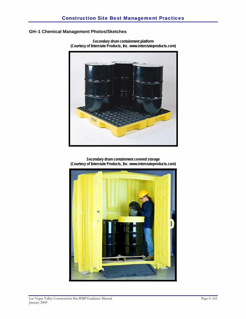
Construction Site Best Management Practices
Las Vegas Valley Construction Site BMP Guidance Manual Page C-161 January 2009
GH–1 Chemical Management Photos/Sketches
Secondary drum containment platform (Courtesy of Interstate Products, Inc. www.interstateproducts.com)
Secondary drum containment covered storage
(Courtesy of Interstate Products, Inc. www.interstateproducts.com)

Construction Site Best Management Practices
Page C-162 Las Vegas Valley Construction Site BMP Guidance Manual January 2009
Solid Waste Management
Definition
The routine collection, recycling, and disposal of accumulated solid waste generated at the construction site.
RATINGS Associated Costs H M L
Implementation
Maintenance
Training
Target Pollutants Removal H M L
Oil and Grease
Nutrients
Sediment
Floatable Material
Metals
Other Construction Waste
GENERAL INFORMATION FIGURES Applicability – Effectiveness: • Debris Management, Cleanup, and Washout –
moderate • Trash Collection/Management – high Most effective when used with: • GH–1 Chemical Management • GH–3 Equipment Maintenance Procedures • GH–5 Spill Containment Plan Alternative BMPs: • None
Photos/Sketches:• GH–2 Solid Waste Management Photos CAD Drawings: • None
Purpose
Solid waste is one of the major pollutants caused by construction activities. By limiting the trash and debris on site and through proper disposal methods, stormwater quality is improved and there is reduced clean up at the completion of a project.
Appropriate Applications
Proper solid waste management is applicable to all construction activities. Solid wastes include, but are not limited to:
• Construction wastes including plastic, glass, rubber, brick, mortar, timber, steel and metal scraps, sawdust, pipe and electrical cuttings, non–hazardous equipment parts, styrofoam and other materials used to transport and package
SWMGH-2

Construction Site Best Management Practices
Las Vegas Valley Construction Site BMP Guidance Manual Page C-163 January 2009
construction materials, materials from the demolition of structures. Highway planting wastes, including vegetative material, plant containers, and packaging materials.
• Domestic waste products, including sanitary wastes, food containers, beverage cans, coffee cups, paper bags, plastic wrappers, cigarettes, and litter generated by the public.
Limitations
Temporary stockpiling of certain construction wastes may not necessitate stringent drainage related controls during the non–rainy season or in desert areas with low rainfall. This practice only applies to non–hazardous solid waste.
Recommended Standards and Specifications
• Education:
• Site supervisor or other designated personnel should oversee and enforce proper solid waste procedures and practices.
• Instruct employees and subcontractors on identification of solid waste and hazardous waste, solid waste storage and disposal procedures. Require that employees and subcontractors follow solid waste handling and storage procedures.
• Hold regular meetings to discuss and reinforce disposal procedures (incorporate into regular safety meetings).
• Prohibit littering by employees, subcontractors, and visitors.
• Wherever possible, minimize production of solid waste materials.
• Collection, Storage, and Disposal:
• Covered dumpsters of sufficient size and number should be provided to contain the solid waste generated by the project operations.
• Prevent clogging of the storm drainage system by removing litter and debris from drainage grates, trash racks, and ditch lines.
• Trash receptacles should be provided in the contractor’s yard, field trailer areas, and at locations where workers congregate for lunch and break periods.
• Construction debris and litter from work areas within the construction limits of the project site should be collected and placed in watertight dumpsters at least weekly regardless of whether the litter was generated by the contractor,

Construction Site Best Management Practices
Page C-164 Las Vegas Valley Construction Site BMP Guidance Manual January 2009
the public, or others. Collected litter and debris should not be placed in or next to drain inlets, stormwater drainage systems, or watercourses.
• Full dumpsters should be removed from the project site.
• Litter stored in collection areas and containers should be handled and disposed of by trash hauling contractors every two weeks or more frequently, if necessary. Notify trash hauling contractors that only watertight dumpsters are acceptable for use on-site. Plan for additional containers and more frequent pickup during the demolition phase of construction.
• Stormwater runoff should be prevented from contacting stored solid waste through the use of berms, dikes, or other temporary diversion structures.
• Solid waste storage areas should be located more than 50 feet from drainage facilities and watercourses and should not be located in areas prone to flooding or ponding.
• Dumpster washout on the project site is not allowed.
• Keep the site clean of litter debris.
• Hazardous Waste Management:
• Segregate potentially hazardous waste from non–hazardous construction site waste. Make sure that toxic liquid wastes (e.g., used oils, solvents, and paints) and chemicals (e.g., acids, pesticides, additives, curing compounds) are not disposed of in dumpsters designated for construction debris. For disposal of hazardous waste, see Chemical Management. Have hazardous waste hauled to an appropriate disposal and/or recycling facility
• Recycling:
• Salvage or recycle useful vegetation debris, packaging and/or surplus building materials when practical. For example, trees and shrubs from land clearing can be converted into wood chips, then used as mulch on graded areas. Wood pallets, cardboard boxes, and construction scraps can also be recycled.
• Sanitary Waste Management:
• Educate employees, subcontractors, and suppliers on sanitary/septic waste storage and disposal procedures and potential dangers to humans and the environment from sanitary/ septic wastes.
• Hold regular meetings to discuss and reinforce disposal procedures (incorporate into regular safety meetings) and to educate new employees.
• Locate portable toilets a minimum of 20 feet away from storm drain inlets, drainage facilities, watercourses, and from traffic circulation. If unable to

Construction Site Best Management Practices
Las Vegas Valley Construction Site BMP Guidance Manual Page C-165 January 2009
meet the 20–foot distance requirement, provide secondary containment for portable toilets.
• Properly connect temporary sanitary facilities that discharge to the sanitary sewer system to avoid illicit discharges. Sanitary and septic systems that discharge directly into sanitary sewer systems, where permissible, should comply with the local health agency, city, county, and sewer district requirements.
• If using an on-site disposal system, such as a septic system, comply with local health agency requirements.
• Ensure that sanitary/septic facilities are maintained in good working order by a licensed service. Use only reputable, licensed sanitary/septic waste haulers.
The effectiveness of solid waste management is enhanced when the following BMPs are also implemented: Chemical Management, Equipment Maintenance Procedures, and Spill Containment Plan.
Recommended Maintenance and Inspection
• On-site trash should be collected and disposed of on a regular basis. Sanitary systems should also be regularly serviced.
• Repair trash containers and dumpsters on an as needed basis. Where possible provide cover for waste containers to prevent the entry of rainwater and loss of contents by wind.
• Maintain a contingency plan in the case that hazardous or toxic materials are discovered on-site.
Post Construction Methods
Long term solid waste practices should be implemented (i.e., dumpsters, and regular trash pickups, etc.)
References
North Central Texas Council of Governments, Integrated Storm Water Management (iSWM) Design Manual for Construction, December 2003.
Washington Department of Ecology, Stormwater Management Manual for Western Washington,
Publications #99–11 through 99–15, August 2001.

Construction Site Best Management Practices
Page C-166 Las Vegas Valley Construction Site BMP Guidance Manual January 2009
GH–2 Solid Waste Management Photos/Sketches
Separate out different wastes from each other for recycling (Courtesy of Maricopa County)
Place signage on the dumpster to prevent improper disposal of hazardous wastes (Courtesy of Maricopa County)

Construction Site Best Management Practices
Las Vegas Valley Construction Site BMP Guidance Manual Page C-167 January 2009
Equipment Maintenance Procedures
Definition
Establish a program of equipment maintenance procedures, which will reduce contamination of on-site soils.
RATINGS Associated Costs H M L
Implementation
Maintenance
Training
Target Pollutants Removal H M L
Oil and Grease
Nutrients
Sediment
Floatable Material
Metals
Other Construction Waste
GENERAL INFORMATION FIGURES Applicability – Effectiveness: • Equipment Storage/Maintenance – high • Debris Management, Cleanup, and Washout –
moderate • Trash Collection/Management – moderate Most effective when used with: • GH–1 Chemical Management • GH–4 Designated Washdown Areas • GH–5 Spill Containment Plan Alternative BMPs: • None
Photos/Sketches:• GH–3 Equipment Maintenance Procedures Photos CAD Drawings: • None
Purpose
Non–sediment stormwater pollution can occur through improper disposal of equipment fluids and disposables such as filters, batteries, and tires. An established program of maintenance procedures can prevent job site pollution and contamination of stormwater.
Appropriate Applications
These procedures are applied on all construction projects where an on-site yard area is necessary for storage and maintenance of heavy equipment and vehicles. Perform equipment maintenance, if possible, back at the maintenance shop.
EMP GH-3

Construction Site Best Management Practices
Page C-168 Las Vegas Valley Construction Site BMP Guidance Manual January 2009
Limitations
None identified.
Recommended Standards and Specifications
• Drip pans or absorbent pads should be used during vehicle and equipment maintenance work that involves fluids, unless the maintenance work is performed over an impermeable surface in a dedicated maintenance area.
• All maintenance areas are required to have spill kits and/or use other spill protection devices.
• Dedicated maintenance areas should be protected from stormwater runon and runoff, and should be located at least 50 feet from downstream drainage facilities and watercourses.
• Absorbent spill clean–up materials should be available in maintenance areas and should be disposed of properly after use. Substances used to coat asphalt transport trucks and asphalt spreading equipment should be non–toxic.
• Use off-site maintenance facilities whenever practical.
• For long–term projects, consider constructing roofs or portable tents over maintenance areas.
• Properly dispose of used oils, fluids, lubricants, and spill cleanup materials. Do not dump fuels and lubricants onto the ground, place used oil in a dumpster, or pour into a storm drain or watercourse. Repair fluid and oil leaks immediately. Provide spill containment dikes or secondary containment around stored oil and chemical drums.
• Properly dispose or recycle used batteries. The effectiveness of equipment maintenance procedures is enhanced when the following BMPs are also implemented: Chemical Management, Designated Washdown Areas, and Spill Containment Plan.
Recommended Maintenance and Inspection
• Maintain waste fluid containers in leak proof condition.
• Vehicle and equipment maintenance areas should be inspected regularly.
• Vehicles and equipment should be inspected on each day of use. Leaks should be repaired immediately or the problem vehicle(s) or equipment should be removed from the project site.

Construction Site Best Management Practices
Las Vegas Valley Construction Site BMP Guidance Manual Page C-169 January 2009
• Inspect equipment for damaged hoses and leaky gaskets routinely. Repair or replace as needed.
Post Construction Methods
None.
References
CALTRANS, State of California Department of Transportation, Construction Site Best Management Practices (BMPs) Manual, March 2003. http://www.dot.ca.gov/hq/construc/stormwater/manuals.htm
U. S. Environmental Protection Agency, Construction Site Storm Water Runoff Control, National Menu of
Best Management Practices for Storm Water Phase II, December 1999. http://cfpub2.epa.gov/npdes/stormwater/menuofbmps/con_site.cfm
Washington Department of Ecology, Stormwater Management Manual for Western Washington,
Publications #99–11 through 99–15, August 2001.

Construction Site Best Management Practices
Page C-170 Las Vegas Valley Construction Site BMP Guidance Manual January 2009
GH–3 Equipment Maintenance Procedures Photos/Sketches
Schematic of used oil containment (Courtesy of CALTRANS)
Schematic of fuelling station (Courtesy of Caltrans)

Construction Site Best Management Practices
Las Vegas Valley Construction Site BMP Guidance Manual Page C-171 January 2009
Designated Washdown Areas
Definition
Procedures and practices that are designed to minimize or eliminate the discharge of concrete waste materials to the storm drain systems of watercourses.
RATINGS Associated Costs H M L
Implementation
Maintenance
Training
Target Pollutants Removal H M L
Oil and Grease
Nutrients
Sediment
Floatable Material
Metals
Other Construction Waste
GENERAL INFORMATION FIGURES Applicability – Effectiveness: • Inlet Drain Protection – high • Debris Management, Cleanup, and Washout –
moderate Most effective when used with: • GH–1 Chemical Management • GH–3 Equipment Maintenance Procedures • GH–5 Spill Containment Plan Alternative BMPs: • None
Photos/Sketches:• GH–4 Designated Washdown Area Photos CAD Drawings: • None
Purpose
Designated washout areas and associated procedures ensure the proper washout of concrete trucks, tools, and equipment and prevents fresh concrete or cement laden mortar from entering a storm drainage system.
Appropriate Applications
Concrete waste management procedures and practices are implemented on construction projects where concrete is used as a construction material or where concrete dust and debris result from demolition activities.
GH-4 WD

Construction Site Best Management Practices
Page C-172 Las Vegas Valley Construction Site BMP Guidance Manual January 2009
• Where slurries containing Portland cement concrete (PCC) or asphalt concrete (AC) are generated, such as from sawcutting, coring, grinding, grooving, and hydro–concrete demolition.
• Where mortar–mixing stations exist.
• Where concrete trucks and other concrete–coated equipment are washed on site. See also Equipment Maintenance Procedures.
Limitations
None.
Planning Considerations
• Educate employees, subcontractors, and suppliers on the concrete waste management techniques described herein.
• The site supervisor or designated personnel should oversee and enforce concrete waste management procedures.
The effectiveness of washdown areas may be enhanced when the following BMPs are also implemented: Chemical Management, Equipment Maintenance Procedures, and Spill Containment Plan.
Recommended Standards and Specifications
• PCC and AC Wastes:
• PCC and AC waste should not be allowed to enter storm drains or watercourses. Instead, PCC and AC waste should be collected and properly disposed of outside the highway right–of–way or placed in a temporary concrete washout structure.
• Install a sign adjacent to each temporary concrete washout structure to inform concrete equipment operators to utilize the installed structures.
• A foreman and/or construction supervisor should monitor on-site concrete working tasks, such as saw cutting, coring, grinding and grooving to ensure proper methods are implemented.
• Saw cutting residue should not be allowed to flow across the pavement, and should not be left on the surface of the pavement. Vacuum slurry residue and dispose in a temporary facility and allow slurry to dry. Dispose of dry slurry residue in accordance with Solid Waste Management.
• Similarly, residue from grinding operations should be picked up by means of a vacuum attachment to the grinding machine.

Construction Site Best Management Practices
Las Vegas Valley Construction Site BMP Guidance Manual Page C-173 January 2009
• On-Site Temporary Concrete Washout Facility Procedures:
• Temporary concrete washout facilities should be located a minimum of 50 feet from storm drain inlets, open drainage facilities, and watercourses, unless determined infeasible by the site supervisor. Each facility should be located away from construction traffic or access areas to prevent disturbance or tracking.
• Temporary concrete washout facilities should be constructed above grade or below grade at the option of the contractor and have sufficient quantity and size to contain all liquid and concrete waste generated by washout operations.
• Perform washout of concrete mixer trucks in designated areas only. A sign should be installed adjacent to each washout facility to inform concrete equipment operators to utilize the proper facilities.
• Wash concrete only from mixer truck chutes into approved concrete washout facility. Washout may be collected in an impermeable bag for disposal.
• Above Grade Temporary Concrete Washout Structure:
• Above grade temporary concrete washout structures should have a minimum length and width of 10 feet or larger to provide sufficient volume to contain all liquid and concrete waste generated by washout operations. If deemed necessary, the length and width of the washout structure may be expanded for more capacity.
• Straw bales, wood stakes, and sandbag materials should conform to the specifications in Organic Filter Barrier and Sand Bag Barrier.
• Plastic lining material should be a minimum of 10–mil polyethylene sheeting and should be free of holes, tears or other defects that compromise the impermeability of the material.
• Below Grade Temporary Concrete Washout Structure:
• Below grade temporary concrete washout should have a minimum length and width of 10 feet or larger to provide sufficient volume to contain all liquid and concrete waste generated by washout operations. If deemed necessary, the length and width of the washout structure may be expanded for more capacity.
• Plastic lining material should be a minimum of 10–mil polyethylene sheeting and should be free of holes, tears or other defects that compromise the impermeability of the material.
• Ensure that the soil base is free of rocks or other debris that may cause tears or holes in the plastic lining material.

Construction Site Best Management Practices
Page C-174 Las Vegas Valley Construction Site BMP Guidance Manual January 2009
• Removal of Temporary Concrete Washout Facilities:
• When temporary concrete washout facilities are no longer required for the work, as determined by the site supervisor, hardened concrete should be broken up, removed, and disposed of in accordance with Solid Waste Management.
• Holes, depressions or other ground disturbance caused by the removal of the temporary concrete washout facilities should be backfilled.
Recommended Maintenance and Inspection
• Monitor on site concrete waste storage and disposal procedures at least weekly.
• Monitor concrete working tasks, such as saw cutting, coring, grinding and grooving to ensure proper methods are employed.
Post Construction Methods
None.
References
CALTRANS, State of California Department of Transportation, Construction Site Best Management Practices (BMPs) Manual, March 2003. http://www.dot.ca.gov/hq/construc/stormwater/manuals.htm
North Central Texas Council of Governments, Integrated Storm Water Management (iSWM) Design
Manual for Construction, December 2003. U. S. Environmental Protection Agency, Construction Site Storm Water Runoff Control, National Menu of
Best Management Practices for Storm Water Phase II, December 1999. http://cfpub2.epa.gov/npdes/stormwater/menuofbmps/con_site.cfm
Washington Department of Ecology, Stormwater Management Manual for Western Washington,
Publications #99–11 through 99–15, August 2001.
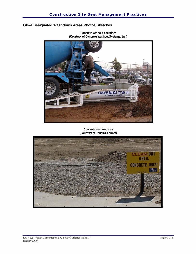
Construction Site Best Management Practices
Las Vegas Valley Construction Site BMP Guidance Manual Page C-175 January 2009
GH–4 Designated Washdown Areas Photos/Sketches
Concrete washout container (Courtesy of Concrete Washout Systems, Inc.)
Concrete washout area (Courtesy of Douglas County)

Construction Site Best Management Practices
Page C-176 Las Vegas Valley Construction Site BMP Guidance Manual January 2009
Spill Containment Plan
Definition
An emergency plan to contain spills of dangerous, hazardous, or toxic wastes which mitigates environmental damage and provides prompt notice to proper authorities.
RATINGS Associated Costs H M L
Implementation
Maintenance
Training
Target Pollutants Removal H M L
Oil and Grease
Nutrients
Sediment
Floatable Material
Metals
Other Construction Waste
GENERAL INFORMATION FIGURES Applicability – Effectiveness: • Inlet Drain Protection – high • Debris Management, Cleanup, and Washout – high Most effective when used with: • GH–1 Chemical Management • GH–3 Equipment Maintenance Procedures • GH–4 Designated Washdown Area Alternative BMPs: • None
Photos/Sketches:• GH–5 Spill Containment Plan Photos CAD Drawings: • None
Purpose
These procedures and practices are implemented to prevent and control spills in a manner that minimizes or prevents the discharge of spilled material to the drainage system or watercourses.
Appropriate Applications
This best management practice (BMP) applies to all construction projects. Spill control procedures are implemented any time chemicals and/or hazardous substances are stored. Substances may include, but are not limited to:
• Soil stabilizers/binders. • Dust Palliatives.
GH-5

Construction Site Best Management Practices
Las Vegas Valley Construction Site BMP Guidance Manual Page C-177 January 2009
• Herbicides. • Growth inhibitors. • Fertilizers. • De-icing chemicals. • Fuels. • Lubricants. • Other petroleum distillates.
Sanitary and Septic Wastes Limitations
The procedures and practices presented in this BMP are general. Contractor should identify appropriate practices for the specific materials used or stored on-site. This BMP only applies to emergency spill response. Refer to Chemical Management for proper storage, use, and disposal of dangerous, hazardous, and toxic wastes that should be observed at all times to minimize the potential for a spill.
Planning Considerations
• Education:
• Educate employees and subcontractors on what a significant spill is for each material they use, and what is the appropriate response for "significant" and "insignificant" spills.
• Educate employees and subcontractors on potential dangers to humans and the environment from spills and leaks.
• Hold regular meetings to discuss and reinforce appropriate disposal procedures (incorporate into regular safety meetings) and establish a program to instruct new employees.
• Spill Response Procedures:
• Significant/Hazardous Spills – for significant or hazardous spills that cannot be controlled by personnel in the immediate vicinity, the following steps should be taken:
• Immediately notify the following:
• Site supervisor and follow up with a written report.
• Local emergency response (Fire department).
• A spills contractor or a Haz–Mat team immediately. Construction personnel should not attempt to clean up the spill until the appropriate and qualified staff have arrived at the job site.

Construction Site Best Management Practices
Page C-178 Las Vegas Valley Construction Site BMP Guidance Manual January 2009
• For spills of federal reportable quantities, in conformance with the requirements in 40 CFR parts 110,119, and 302, the contractor should notify the National Response Center (see contact number in table below).
• Any applicable divisions within the Nevada Division of Environmental Protection (NDEP) should also be contacted. Notification should first be made by telephone and followed up with a written report.
Agency Situation Phone
Nevada Division of Environmental Protection (NDEP) – Spill Report Hotline
Routine Business 888–331–6337
National Response Center Emergency 800–424–8802 Local Fire Department/District Emergency 911
• Post Spill Response Procedures:
• Spills should not be buried or washed with water.
• Used clean up materials, contaminated materials, and recovered spill material that is no longer suitable for the intended purpose should be stored and disposed of in conformance with the special provisions.
• Water used for cleaning and decontamination should not be allowed to enter storm drains or watercourses and should be collected and disposed of in accordance with Chemical Management. Water overflow or minor water spillage should be contained and should not be allowed to discharge into drainage facilities or watercourses.
• Proper storage, clean–up and spill reporting instruction for hazardous materials stored or used on the project site should be posted at all times in an open, conspicuous and accessible location.
• Waste storage areas should be kept clean, well organized and equipped with ample clean–up supplies as appropriate for the materials being stored. Perimeter controls, containment structures, covers and liners should be repaired or replaced as needed to maintain proper function.
The effectiveness of spill containment is enhanced when the following BMPs are also implemented: Chemical Management, Equipment Maintenance Procedures, and Designated Wash–down Areas.
Recommended Maintenance and Inspection
• Comply with suggestions and requirements set by local fire department.
• Verify weekly that spill control clean up materials are located near material storage, unloading, and use areas. Restock appropriate clean–up materials after a spill incident has occurred.

Construction Site Best Management Practices
Las Vegas Valley Construction Site BMP Guidance Manual Page C-179 January 2009
• Update spill prevention and control plans and stock appropriate clean–up materials whenever changes occur in the types of chemicals used or stored on-site, or after a spill incident has occurred.
Post Construction Methods
None.
References
CALTRANS, State of California Department of Transportation, Construction Site Best Management Practices (BMPs) Manual, March 2003 http://www.dot.ca.gov/hq/construc/stormwater/manuals.htm
Tacoma Public Works Environmental Services, City of Tacoma Surface Water Management Manual
Volume II, Construction Stormwater Pollution Prevention, January 1993. http://www.ci.tacoma.wa.us/waterservices/permits/Manual.htm
U. S. Environmental Protection Agency, Construction Site Storm Water Runoff Control, National Menu of
Best Management Practices for Storm Water Phase II, December 1999. http://cfpub2.epa.gov/npdes/stormwater/menuofbmps/con_site.cfm
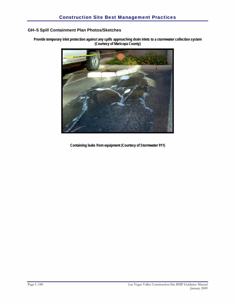
Construction Site Best Management Practices
Page C-180 Las Vegas Valley Construction Site BMP Guidance Manual January 2009
GH–5 Spill Containment Plan Photos/Sketches
Provide temporary inlet protection against any spills approaching drain inlets to a stormwater collection system (Courtesy of Maricopa County)
Containing leaks from equipment (Courtesy of Stormwater 911)
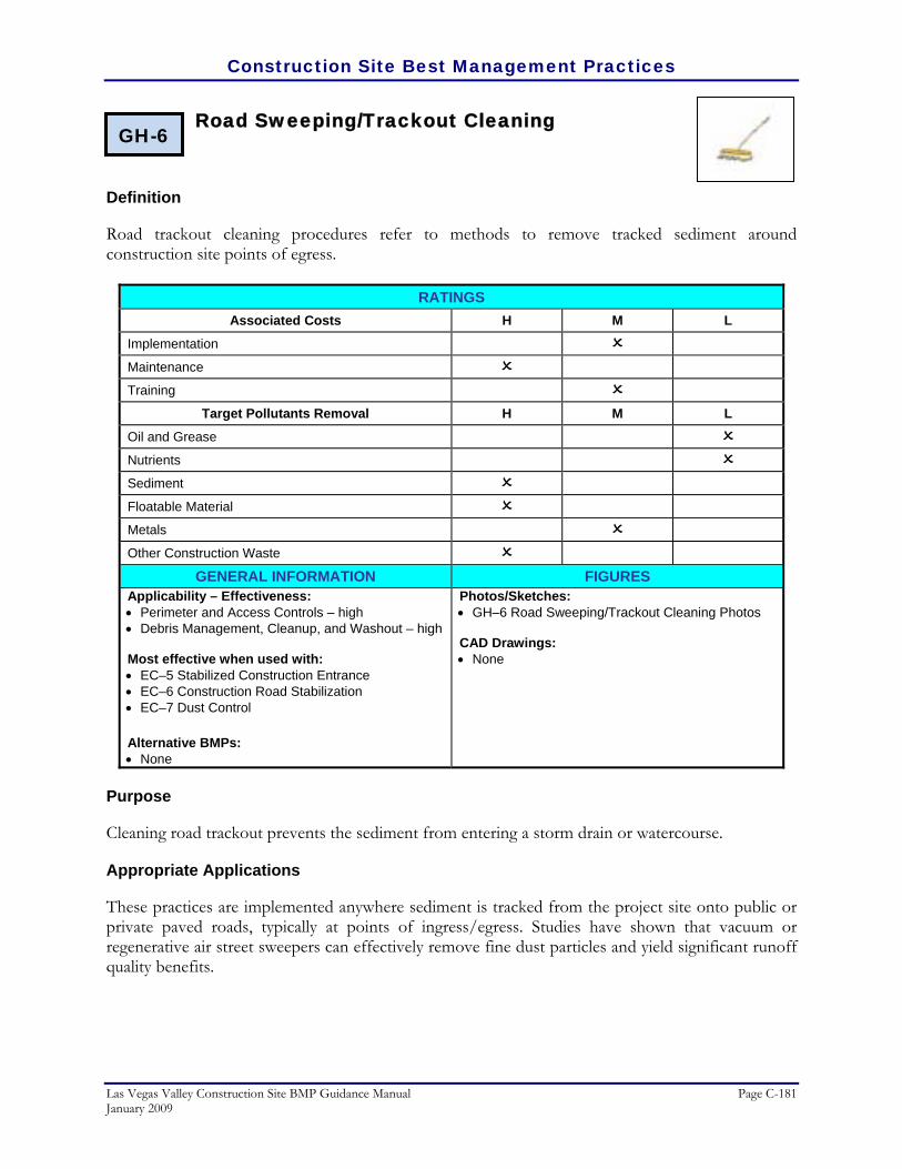
Construction Site Best Management Practices
Las Vegas Valley Construction Site BMP Guidance Manual Page C-181 January 2009
Road Sweeping/Trackout Cleaning
Definition
Road trackout cleaning procedures refer to methods to remove tracked sediment around construction site points of egress.
RATINGS Associated Costs H M L
Implementation
Maintenance
Training
Target Pollutants Removal H M L
Oil and Grease
Nutrients
Sediment
Floatable Material
Metals
Other Construction Waste
GENERAL INFORMATION FIGURES Applicability – Effectiveness: • Perimeter and Access Controls – high • Debris Management, Cleanup, and Washout – high Most effective when used with: • EC–5 Stabilized Construction Entrance • EC–6 Construction Road Stabilization • EC–7 Dust Control Alternative BMPs: • None
Photos/Sketches:• GH–6 Road Sweeping/Trackout Cleaning Photos CAD Drawings: • None
Purpose
Cleaning road trackout prevents the sediment from entering a storm drain or watercourse.
Appropriate Applications
These practices are implemented anywhere sediment is tracked from the project site onto public or private paved roads, typically at points of ingress/egress. Studies have shown that vacuum or regenerative air street sweepers can effectively remove fine dust particles and yield significant runoff quality benefits.
GH-6

Construction Site Best Management Practices
Page C-182 Las Vegas Valley Construction Site BMP Guidance Manual January 2009
Limitations
• Sweeping and vacuuming may not be effective when soil is wet or muddy. • Mechanical brush sweepers may only remove coarser particles.
Recommended Standards and Specifications
• Visible sediment tracking should be swept and/or vacuumed daily. For smaller areas of trackout, kick brooms can be used. For larger areas, consider mechanical brush or vacuum sweepers. Some mechanical sweepers can remove debris and dust particles down to 2.5 microns.
• Conduct sweepings at least once per week during the project operations, and prior to any predicted rainfall events.
• Consider incorporating the removed sediment back into the project, rather than hauling off-site to disposal.
Recommended Maintenance and Inspection
• Inspect ingress/egress access points daily and sweep tracked sediment as needed.
• Properly dispose of any unknown substances or objects that may be potentially hazardous.
• Adjust brooms frequently; maximize efficiency of sweeping operations.
• After sweeping is finished, sweeper water can be reused or disposed of at an approved dump–site.
Post Construction Methods
In most cases, the municipality will continue with road sweeping operations after construction is complete.
References
CALTRANS, State of California Department of Transportation, Construction Site Best Management Practices (BMPs) Manual, March 2003. http://www.dot.ca.gov/hq/construc/stormwater/manuals.htm
Kamber Engineering, Gaithersburg, Maryland, Sedimentation and Erosion Control, An Inventory of Current
Practices, USEPA, April, 1991.

Construction Site Best Management Practices
Las Vegas Valley Construction Site BMP Guidance Manual Page C-183 January 2009
GH–6 Road Sweeping/Trackout Cleaning Photos/Sketches
Road sweeping (Courtesy of Douglas County)
Construction site trackout (Courtesy of Maricopa County)

THIS PAGE LEFT BLANK INTENTIONALLY

THIS PAGE LEFT BLANK INTENTIONALLY

3010 West Charleston BoulevardSuite 100
Las Vegas, Nevada 89102-1944PH: (702) 878-8010
FAX: (702) 878-7833
www.mwhglobal.com