Embed Size (px)
Citation preview

V
FINAL REPORT
STUDY OF THIN FILM LARGE AREA
PHOTOVOLTAIC SOLAR ENERGY CONVERTER BY
W. J. DESHOTELS and F. AUGUSTINE
\
NASA CR 54343
PREPARED FOR
NATIONAL AERONAUTICS AND SPACE ADMINISTRATION
CONTRACT NAS 3-2795
GPO PRICE $
OTS PRICE(S) $
OCTOBER 30, 1964
Hard copy (HC) 2-oi9 Microfiche (M F)
ELECTRONIC RESEARCH DIVISION
CLEVITE CORPORATION

NOTICE
This report was prepared as an account o f Government sponsored work. Neither the United States, nor the National Aeronautics and Space Administration (NASA), nor any person acting on behalf of NASA:
A.) Makes any warranty or representation, expressed or implied, with respect to the accuracy, completeness, or usefulness of the information contained in this report, or that the use of any information, apparatus, method, or process disclosed in this report may not infringe privately owned rights; or
B.) Assumes any liabilities with respect to the use of, or for damages resulting from the use o f any information, apparatus, method or process disclosed in this report.
As used above, "person acting on behalf of NASA" includes any employee or contractor of NASA, or employee o f such contractor, to the extent that such employee or contractor of NASA, or employee of such contractor prepares, disseminates, or provides access to, any information pursuant to his employment or contact with NASA, or hiu employment with such contractor.
Requests for copies of this report should be referred to:
National Aeronautics and Space Administrotion
Office of Scientific and Technical Information Attention: AFSS-A Washington, D. C. 20546

. NASA CR-34343
CONTRACTOR REPORT
STUDY OF THIN FILM LARGE AREA
PHOTOVOLTAIC SOLAR ENERGY CONVERTER
By W. J. Deshotels and F. Augustine
Prepared under Contract NAS 3-2795 by C levit e Corporation
Electronic R e s ear ch Division Cleveland, Ohio 44 108
Technical Management Space Power Systems Division
L. R. Scudder, MS500-201
Lewis Research Center Cleveland, Ohio
NATIONAL AERONAUTICS AND SPACE ADMINISTRATION

TABLE O F CONTENTS
Page
LIST O F ILLUSTRATIONS LIST OF TABLES
Section Title
SUMMARY 1. 0 INTRODUCTION 2. 0 EVAPORATED FILMS
2. 1 Equipment 2. 2 Substrates
2. 2, 1 Glass 2. 2. 2 H-Film 2. 2. 3 Textolite
2. 3 CdS Material 2. 4 Evaporation Process
2. 4. 1 2. 4. 2
Optimum Film Parameters Evaporation Rate, Cell Efficiency, and Thickness
3. 0 CELL PROCESSING 3. 1 Collector Electrode 3. 2 Barr ie r Process
3. 2. 1 Slurry Process 3. 2. 2
3. 3 Lamination 3. 4 Curling Problem
Analysis of Slurry Samples
4. 0 CELL STABILITY 5. 0 CELL AND ARRAY CONSTRUCTION AND
PERFORMANCE 5. 1 H-Film Cell Ar rays 5. 2 Glass Backed Cel l s 5. 3 Conversion Efficiency Measurement
ii iii
1
1 2 2 3 3 6 6
7 7
7
8 8
8
20 20 20 21 21 22
25 25 26 30
REFERENCES ABSTRACT
i
30

LIST OF ILLUSTRATIONS
Figure
1
2
3
4
5
6
7
8
9
Title Page
CdS Evaporation Set-Up -- 12" Vacuum System 4
Quartz Crucible for CdS Evaporation 5
Effect of Deposition Rate on Cell Efficiency 9
Effect of Film Thickness on OCV and SCC 10
I-V Curve of CdS Film Between Evaporated Gold Electrodes, Before Heating 14
I-V Curve of CdS Film Between Evaporated Gold Electrodes, After Heating 15
Deterioration of CdS Film Cells 23
Construction of Flexible H-Film Substrate Backwall Cell Arrays 2 7
Construction of Glass Substrate Large Area Backwall Cell 29
ii

LIST O F TABLES
Table No.
I
I1
I11
IV
Title
Resistance Between Evaporated Metal Electrodes and In-Hg Amalgam Electrode
Resistance Between Evaporated Gold Electrodes and In-Hg Amalgam Electrodes
CdS Cells on H-Film with Evaporated Gold and Nickel Collector Electrodes
Test Data of Backwall Cells Delivered to Contract Monitor
Page
12
17
18
28
iii

STUEY OF THIN F I L M LARGE AREA PHOTOVOLTAIC SOLAR ENERGY CONVERTER
Warren J. Deshotels and Frank Augustine Electronic Research Division, Clevite Corporation
SUMMARY
A process for fabricating thin film CdS backwall solar cells on polyimide plastic foil substrates has been developed. consists of vacuum evaporating approximately 50 microns of indium- doped CdS onto a lapped surface of 0. 002" thick DuPont H-Film at 2OO0C, processing a bar r ie r on the CdS by applying a water s lur ry of Cu 0 and heating, contacting the bar r ie r with conductive si lver paint, 2 and then laminating the cel l to an 0. 0Olf f thick film of Mylar using a nylon plastic adhesive.
This process
Other transparent insulating substrate mater ia ls have been evaluated as substrates for backwall film cells. the vacuum evaporation of CdS films have been studied and a trade-off made between low film resis tance yielding low open circuit voltages and higher film resistance causing appreciable s e r i e s res is tance effects.
Factors affecting
The plastic substrate cell has reached the 1. 5 to 2 . 0% efficiency level. Further improvements a r e anticipated since efficiencies greater I
than 470 have been obtained with insulating glass substrate cells.
1. 0 INTRODUCTION Thin film solar cells a r e still in the early developmental stages.
However, these cells show promise of realizing large a rea low cost arrays which a r e very light in weight, and capable of extreme compac- tion during launch and ascent into orbit,
1
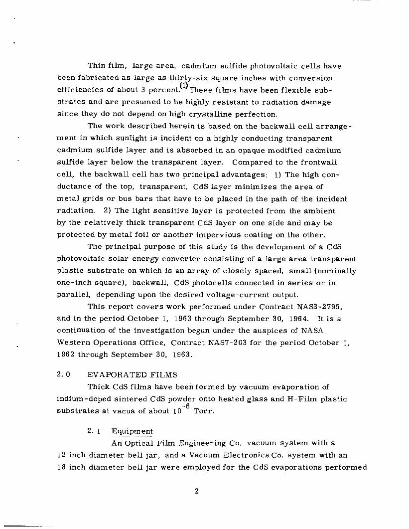
Thin film, large area, cadmium sulfide photovoltaic cells have been fabricated a s large a s thirty-six square inches with conversion efficiencies of about 3 percent.(l)These films have been flexible sub- s t r a t e s and are presumed to be highly resis tant to radiation damage since they do not depend on high crystalline perfection.
The work described herein is based on the backwall cel l arrange- ment in which sunlight is incident on a highly conducting transparent cadmium sulfide layer and is absorbed in an opaque modified cadmium sulfide layer below the transparent layer. Compared to the frontwall cell, the backwall cell has two principal advantages: 1) The high con- ductance of the top, transparent, CdS layer minimizes the a r e a of metal gr ids or bus bars that have to be placed in the path of the incident radiation. by the relatively thick transparent CdS layer on one side and may be protected by metal foil or another impervious coating on the other.
photovoltaic solar energy converter consisting of a large area transparent plastic substrate on which is an a r r a y of closely spaced, small (nominally one-inch square), backwall, CdS photocells connected in se r i e s or in parallel, depending upon the desired voltage-current output.
This report covers work performed under Contract NAS3-2795, and in the period October 1, 1963 through September 30, 1964. It is a continuation of the investigation begun under the auspices of NASA Western Operations Office, Contract NAS7-203 for the period October 1,
1962 through September 30, 1963.
2 ) The light sensitive layer is protected from the ambient
The principal purpose of this study is the development of a CdS
2 . 0 EVAPORATED FILMS Thick CdS films have been formed by vacuum evaporation of
indium-doped sintered CdS powder onto heated glass and H-Film plastic substrates at vacua of about 10 Torr. -6
2. 1 Equipment An Optical Film Engineering Co. vacuum system with a
12 inch diameter bell j a r , and a Vacuum Electronics Ca. system with an 18 inch diameter bell j a r were employed for the CdS evaporations performed
2

under this contract.
substrate heaters positioned above the substrate, and with inner pyrex glass chambers to contain the evaporation proper.
Both systems were provided with tungsten coil
Figure 1 i l lustrates the evaporation set-up for the smaller system. either glass o r H-Film clamped in a frame. s o that they formed the lower surface of an aluminum box-like chamber. Several different evaporation sources were evaluated, but a quartz c ru- cible as shown in Fig. 2 w a s evolved which gave best all around resul ts and was used for most of the evaporations of this contract. The advan- tage of this design is that the crucibles can be readily removed and cleaned and replaced, and they a r e independent of the heater coils. Also, the design permits insertion of a thermocouple in the center w e l l where the couple does not come into direct contact with highly corrosive sulfur vapors.
The substrate holder was designed to hold a 41° x 4 " substrate of The substrates were mounted
The hot w a l l chamber technique w a s employed for these evaporations using an inner pyrex glass cylinder to contain the CdS vapors, and an adjacent outer pyrex glass cylinder wound with a tung- sten filament as a source of heat.
The evaporation set-up for the larger Veeco system w a s similar except that the substrate holder w a s 9" x 9" in s ize designed to hold fou r 4If x 4 " glass or plastic substrates, and with proportionately larger cylinder w a l l and source to substrate dimensions, etc.
2. 2 Substrates Var ious insulating substrates have been tried with some
degree of success for vacuum evaporated CdS film solar cells.
2. 2. 1 Glass A heat resistant borosilicate glass supplied by the
Cincinnati Gasket Packing and Mfg. Co. w a s used for most of the ear l ier work of this contract. used in 4 " x 4 " plates. evaluations, the g lass was scored into eighths prior to CdS evaporation and broken into
This glass w a s I / 16 inch in thickness and w a s To obtain smaller specimens for experimental
x 2 " pieces after film formation.
3

*
Substrate Heater Coil
Substrate
Inner Pyrex W a l l
Outer Pyrex Wall with Heater Coil
Evaporation Crucible
Heat Shield
Heater Coil
Thermocouple Well
Base Plate
FIG. 1 CdS EVAPORATION SET-UP, 12" Vacuum Syetem
4

B a
1 ua Cross Section View Material: G. E. type 204 Clear
Fused Quartz Tubing Approx. 1 mm wall
FIG. 2 QUARTZ CRUCIBLE FOR CdS EVAPORATION
5

To improve the adherence of the thick CdS deposited layer, the glass was lapped on one surface with 1000 gr i t silicon carbide abrasive, cleaned with detergent, alkali, and several boiling distilled water r inses prior to evaporation.
2. 2. 2 H-Film After reasonably reproducible resul ts w e r e obtained
on glass substrates, a thin polyimide plastic foil, trade-marked '?H-Film w a s secured from the duPont Co. and used as a flexible lightweight substrate for CdS film cells. This mater ia l is characterized as a high temperature dielectric with outstanding mechanical properties from liquid helium temperature up to 500 to 600°C. It is optically compatible with CdS for rearwal l cel l operation as i t transmits light well for wave- lengths greater than 0. 5 microns. It is available in various width rolls in thicknesses of 0. 001 and 0. 00211, suitable fo r the present application.
Due to the extreme flexibility of this H-Film plastic i t had to be held clamped in metal f rames for evaporation of CdS and subsequent cell processing. only when the H-Film w a s lapped with 1000 grit silicon carbide abrasive to yield a roughened surface for the CdS. detergent, and acid solutions followed by distilled water r inses was necessary. in securing adherent well-structured CdS films.
Reasonable adherence of CdS w a s secured
Also careful cleaning in alkali,
A stannous chloride sensitizing dip w a s found to be beneficial
2. 2. 3 Textolite A silicone glass laminate, trade-marked I'Textolite1l,
as supplied by the General Electric Company w a s tr ied as a substrate in one se r i e s of experiments. down to 0. 008", and is a translucent (approximately 757'0 transmission) plastic with much greater stiffness than the thinner H-Film, making it easier to handle. continuously without altering its mechanical and optical properties.
This mater ia l w a s secured in thicknesses
It is able to withstand temperatures up to 250°C
6

This material w a s a l so lapped and cleaned pr ior to CdS film evaporation. However, film adhesion was generally poor, though there were indications of good adherence on some smaller a reas . Thus, i t is possible that improved cleaning or surface sensitizing might yield a satisfactorily adherent CdS film suitable for thin film solar cells.
2. 3 CdS Material The charge used for evaporating CdS fi lms is a mixture of
doped and undoped sintered material made from luminescent grade cadmium sulfide secured from the General Electric Company. cadmium sulfide is sintered in quartz tubes on the following schedule:
1 hour under vacuum at 825°C. 1 hour under argon (790 mm Hg) at 1225°C. Cooled naturally to room temperature.
The
The resulting hard boules a r e ground in mor ta r and pestle and stored until use.
The doped mater ia l (0, 1 mol% indium as sulfide) is blended with undoped mater ia l in the approximate ratio of 1:2 .
portion is adjusted with each lot of mater ia l to yield the desired CdS film conductivity. In a typical evaporation 16 g rams of the mixture a r e charged into the crucible and about 1 3 grams are actually evaporated to give a film of severa l mi l s thickness,
The exact pro-
2 .4 Evaporation Process 2. 4. 1 Optimum Film Parameters
Whenever possible, film resistivity, c a r r i e r con- centration and thickness were measured on at least one film sample from each evaporation. the Hall mobility is calculated. These fi lm characterist ics have been compared with the open circuit voltage, short circuit current and con- version efficiency of the cells fabricated from the films,
From the resistivity and c a r r i e r concentration
7

The result is a s e t of specifications such that a
film, meeting these specifications, might reasonably be expected to yield good quality cells. These are:
Film Resistivity Car r i e r Concentration 8 x 10 cm - 10 x 10 cm Hall Mobility 20 cm -volt-l-sec '-27 cm -volt -sec Thickness 50 microns - 60 microns
0. 025 ohm-cm - 0. 035 ohm-cm 18 - 3 18 -3 2 - 2 -1 -1
2. 4. 2 Evaporation Rate, Cell Efficiency and Film Thickness -- -- The data taken on cells from sixty evaporations were
examined in various ways. efficiency of the best cell from an evaporation w a s plotted against the deposition r a t e for that evaporation. These data a r e shown in Fig. 3, and it appears that the best cells a r e obtained for the highest deposition rates. Indeed, with but one exception, no cells with efficiency greater than two percent were obtained a t an evaporation r a t e l e s s than about 0. 19 micron per second. When open circuit voltage and short circuit current were plotted in the same manner, it w a s observed that the maxi- mum attainable current also increased with deposition rate, while no such trend w a s observed for the open circuit voltage.
One interesting result w a s obtained when the
In Fig. 4 the variation in cel l open circuit voltage and short circuit current a r e plotted against the thickness of the CdS film. In general both increase with increasing film thickness.
3 .0 CELL PROCESSING 3. 1 Collector Electrode
It w a s suspected that the indium peripheral electrode con- tacting the n-type CdS might be responsible for a t least par t of the deterioration observed. behavior of cel l 102-7 which had an electroplated rhodium electrode in
place of the indium. candidates for the role of contact to n-type CdS. plated and some were vacuum evaporated.
Indeed, this seemed to be borne out by the
A number of metals were investigated a s possible Some were electro-
In a few instances, both
8

. 02 . 04 . 06 . 08 . 10 . 12 . 14 . 16 . 18 . 20 . 22 . 24 . 26
Depos i t ion rate, micron/ sec
FIG. 3 E F F E C T O F DEPOSITION R A T E O N C E L L E F F I C I E N C Y
9

Film Thickness, microns
FIG. 4 E F F E C T O F FILM THICKNESS O N OCV AND SCC

methods w e r e tr ied with the same metal. contacts were obtained with Ni, Rh, and Pt. Electroplated rhodium
w a s quickly discarded because of its strongly acid plating bath. Any pinhole in the film w a s quickly attacked with subsequent lifting of the film around the hole. the f i l m .
lifting would occur ra ther often. bath worked very well.
Successfully electroplated
Rhodium would quickly plate out on both sides of A s imilar result was observed at the edge of the f i l m where
Nickel, plated from a Watts type Platinum also gave good electrodes.
The resistance between two nickel s t r ipes electroplated on a CdS f i l m w a s compared with the resistance measured between two mercury-indium amalgam str ipes of s imilar geometry. There w a s no significant difference between the two. An i - V plot obtained from one of the nickel s t r ipes (compared with an amalgam str ipe for reference) w a s a straight line through the origin even for quite high current den- s i t ies of several amperes per square centimeter. be easily and quickly CdS film with the plating solution.
Although nickel may plated, it is considered undesirable to wet the
Vacuum evaporated electrodes were considered next. Stripes of Ni, Al, Ag, Au, Cu, Mn, Mg, Cr , Sn, Pb, Fe, and Pt, were evaporated on CdS. mercury-indium alloy s t r ipe w a s placed on the CdS a short distance away from each. The i - V curve t racer using the 4-probe method was used to plot an i-V characterist ic for current flowing into one contact, through the CdS f i l m and out the other contact. w e r e used. the resis tance of the contact-CdS combination w a s obtained from the slope of the i - V characteristic. electrode except platinum which was excluded simply because it w a s too difficult to evaporate a sufficiently thick layer.
In order to compare these various electrodes, a
Both voltage polarities Whenever a straight line through the origin w a s obtained,
This measurement w a s made for each
The measurements were repeated after the film, with electrodes, had been heated on a 300°C hot plate in a i r . summarized in Table I.
The data a r e
11

Q) a 0 k 0 Q)
c,
d w cd M E 4
ii 4
8 h l-l
a G cd m Q) a 0
4
0
0
M 0
0
u '5 3 h i co 0
0
l-l
N
0
M 0
0
d d
0
cv M
0
4 cv 0
In 0
0
0
l 0
h E
0
4 0
0
M 0
0
cv 0 0
0
0
-5 % h E 0 cv 0
co M
0
0
r: 0 3
s h
*
4 0
0
w 0 0
0
0 N
0
W cv 0
0 cv 0
M 0
0
0
Ei 0 A E t? $-I
0
In w 0
0
a 0
*;
8 I
z
0 4
12

These resis tances a re remarkably low. There is doubt about the validity of the last silver measurement because the si lver s t r ipe had been noticeably reduced in thickness and a r e a and had turned quite black. For this same reason, manganese, magnesium, tin, lead and iron were eliminated. possibly sulfodized to be considered f o r reliable contacts. Thus, only gold, chromium, and nickel, a r e left after eliminating the non-ohmic contacts aluminum and copper. The principal objection to chromium and nickel is the difficulty of soldering to these metals. other hand is inert, easily solderable and easy to evaporate. Therefore, several additional gold s t r ipes were vacuum evaporated onto various CdS fi lms and a careful examination of the Au-CdS contact w a s undertaken. Figure 5 shows the voltage current relationship for CdS film 147-2 between evaporated gold electrodes. after the gold evaporation. long and 1/8-inch wide. The stripes were 11/16-inch apart. In Fig. 5, curve 1 shows the linearity for a maximum current of 0. 93 mA a t 4 mV corresponding to a resistance of 4. 3 ohm. The maximum current den-
-2 2 si ty w a s 1, 15 mA-cm , the a rea of the gold electrodes was 0. 806 cm . Curve 2 shows the linearity for a maximum current of 112 mA at 400 mV, corresponding to a resistance of 3. 58 ohms.
-2 density in this case was 139 mA-cm curves a r e different show that gold electrodes are not truly ohmic. the other hand, the fact that the slope changed only about 20 percent while the current density increased by a factor of more than 100 shows the departure from Ohm's law is quite small. It should be pointed out he re that the resistivity of the cadmium sulfide film w a s 0. 026 ohm-cm before heating.
These metals a r e too easily oxidized and
Gold on the
These curves were obtained immediately The gold electrodes a r e s t r ipes one-inch
The maximum current . The fact that the slopes of the
On
After these measurements, the film w a s heated for one hour a t 250°C in the oven used for processing photovoltaic cells. ments described above were repeated and the data a r e shown in Fig. 6.
The heating decreased the resistance measured between the gold stripes. The slope of curve 1, Fig. 6 shows a resistance of 3. 26 ohms
The measure-
13

14

h
cv aJ
3 U k 0
0 0 cv h P Q,
cd CI m
cd c C N
k 0 c
t
G-l
!-I
4
c
.r(

for CdS 147-2 a t 1. 23 mA and 4 mV, and the slope of curve 2 shows a
resis tance of 2. 76 ohms at 145 mA and 400 mV. a r e 1. 53 mA-cm and 180 mA-cm respectively.
The current densities -2 -2
Two indium-mercury amalgam str ipes were painted on the f i lms and the measurements repeated for current flowing between the two amalgam str ipes , and between one gold and one amalgam stripe. Finally, an overlay of a i r dried silver paint w a s placed on each gold s t r ipe and a l l the measurements repeated. Always, a straight line through the origin w a s obtained, and invariably, a smal l change in resistance accompanied a large change in current density. summarized in Table 11. when the current density increases and upon heating the films. drying silver paint applied to reduce the resistance of the gold film reduced the measured resistance and resist ivity by more than half for
CdS 147-2. The two gold s t r ipes were 11/ 16-inch apart; the amalgam s t r ipes were 51 16-inch apart.
-3 gam str ipes w a s 4. 1 x 10 ohm-cm. Therefore, the resistance of an 11/ 16-inch length of the CdS film should be 0. 64 ohm. The resis tance of this length of the film, measured via the gold electrodes w a s 1. 2 7
The data a r e It is apparent that the resis tance decreases
The air
The resistivity, determined via the amal-
ohms. with si lver paint, have about twice the contact res is tance of amalgam electrodes. This does not mean, of course, that gold is the best elec- trode that one may put on n-type CdS; but merely that i t is the most convenient electrode mater ia l of those investigated.
Thus one may conclude that evaporated gold electrodes backed
Three CdS a r r a y s on H-Film were processed in experi- ments to evaluate further the n-electrode mater ia l and electrode con- figuration for arrays. fo r g lass backed cells. on H-Film cells. Nickel is difficult to evaporate, while evaporating gold is quite easy. evaporated nickel v s evaporated gold as electrode material. data of Table 111 there appears to be no significant advantage of one meta l over the other.
Electroplated nickel is used almost exclusively It is more conyenient toevaporate the n-electrode
The three a r rays on H-Film were to compare From the
16

m Q, a 0 k 0 al c,
Li E
E 4
cd M cd 4
I
5 a c cd m Q, a 0 k V al c,
4 w a 4 s a Q,
td k 0 a cd
c,
ti $
$ 2
c, ; Q,
cd m m Q,
c,
.Id
E
u H
! m 4 !3
E 0
(D 0 co 0
? m cd
m Q, a 0 k 0 al
c,
4 w Ccl 0
2 2 Y
a
Q, m
Q, VI E E % %
co
d o ) . m d d
E
E %
0 I
M I 0
x d
d
4
E
E 9
0 I
CQ I 0
x 1 - 4
m & r-4
d E A A 0 0 m a l
0 0
cv I
ET Y E 4 Y E 4
I + d
c v d . .
E E 9 % m c o m c v . .
M c .Id c,
2 x k Q,
2
E
E -8
0 I
m I 0
x r-4
d
4
E V I
E a 0
m I 0
x r-4
co
E % o) cv 0
0 3 I
E 4 0 I
4
rl
E % co d
cv I
E V I
4
0
co
1 7

TABLE 111. CdS Cells on H-Film with Evaporated Gold and Nickel Collector Electrodes
Fill Efficiency i Area, oc , sc’ V
% Electrode Cell No. volts mA Cn? . Factor
Evap. Au 178Ha 178Hb 178Hc 178Hd 178He 178Hf 178Hg 178Hh 178Hi Average
Ehap. Au 180Ha 180Hb 180Hc l8OHd 180He 180Hf 180Hg 180Hh 180Hi Average
Evap. Ni 183Ha l83Hb 183Hc 183Hd l83He 183Hf l83Hg 183Hh 183Hi
. 38 26. 2 3. 0
. 3 8 27.2 3. 1
. 38 26.4 2. 9
. 3 7 21.5 2. 6
. 37 24. 2 2. 3
. 37 24. 2 2. 3
. 3 7 27.4 2. 6
. 3 6 26. 8 2, 6
. 3 5 22.3 2. 6
. 4 8
. 5 7
. 4 2
. 56
. 4 8
. 4 8
. 5 0
. 5 0
. 4 7
1. 7 1. 9 1. 5 1. 7 1. 9 1. 9 2. 0 1. 9 1. 4
. 42 23. 7 2. 6
. 3 9 28.6 2. 6
. 3 8 23. 0 2. 6 - 4 0 29. 6 2. 6 . 4 0 27. 8 2. 6 . 3 8 21.4 2. 6 , 37 26. 6 2. 6 . 34 25. 6 2. 6 . 3 7 17.7 2. 6
. 4 3 20. 8 2. 6
. 4 3 17. 4 2. 6
. 4 4 14. 0 2. 6
. 42 16. 2 2. 6
. 4 1 21.4 2. 6
. 42 17. 0 2. 6
. 4 1 18. 0 2. 6
. 4 1 16. 8 2. 6
.42 16. 7 2. 6
. 5 0
. 4 2
. 4 5
. 4 7
. 4 2
. 4 1
. 4 3
. 4 0 40
. 5 4
. 5 3
. 5 5
. 52
. 4 8
. 5 4 . 61
. 4 2 e54
1. 8 f 0. 2
1. 9 1. 8 1. 6 2. 0 1. 8 1. 4 1. 6 1. 3 1. 0
1 . 6 f O . 2
1. 9 1. 6 1. 3 1 . 4 1. 6 1. 5 1. 7 1. 0 1. 5
Average 1 . 5 f 0 . 2
18

In a r r a y 178H, the two cells, 178H-c and 178H-i showed very high se r i e s resistance in the forward direction. uncommon with evaporated gold electrodes, and is usually denoted by a sharp break in the forward characteristic as the curve c ros ses the horizontal (voltage) axis. The slope of the curve in the f i r s t quadrant may change by an order of magnitude from that in the fourth quadrant. The sharp break in the characteristic usually disappears if the contact is heated, but the overall resistance of the cell remains high.
This is not
The sharp break is not as noticeable in a r r a y 180H and is not present at all in a r r a y 183H, the latter having evaporated nickel electrodes.
Attempts were made to use an evaporated metal grid on the H-Film, beneath the CdS layer, as a current collector from the n-type CdS. Gold had been found to adhere reasonably wel l to H-Film, so gold gr ids were vacuum evaporated onto the H-Film and built up in thickness by electroplating nickel onto the gold. 1 /16" wide s t r ipes located on l / 2 I f centers, stretching ac ross the H-Film from one edge to the opposite edge and interconnected with a single 1 / 8 wide central transverse stripe. partially removed during cleaning prior to the CdS evaporation. attempt was made with extreme care to keep the grid and H-Film clean so that only a distilled water rinse w a s required prior to evaporation. In this case the evaporated CdS layer pulled the grid free of the H-Film. Similar attempts on glass substrates caused some difficulty with shorts between the bar r ie r layer and grid through pinholes in the CdS layer. However, these difficulties were subsequently overcome and the above described collector grid beneath the CdS layer w a s successfully used on the large area (4" x 4") cells.
The grid consisted of
In the first attempt, the grid w a s A second
19
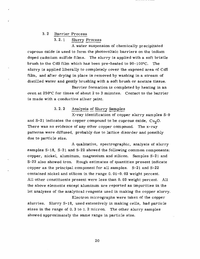
3. 2 Bar r ie r Process 3. 2. 1 Slurry Process
A water suspension of chemically precipitated cuprous oxide is used to form the photovoltaic b a r r i e r s on the indium doped cadmium sulfide films. brush to the CdS film which has been pre-heated to 90-100°C. s lur ry is applied liberally to completely cover the exposed area of CdS f i l m , and after drying in place is removed by washing in a s t ream of distilled water and gently brushing with a soft brush or acetate tissue.
Bar r ie r formation is completed by heating in an
The s lu r ry is applied with a soft brist le The
oven at 25OOC for times of about 2 to 3 minutes. is made with a conductive si lver paint.
Contact to the ba r r i e r
3. 2. 2 Analysis - of Slurry Samples X-ray identification of copper s lur ry samples S-9
and S-21 indicates the copper compound to be cuprous oxide, Cu20. There was no evidence of any other copper compound. patterns w e r e diffused, probably due to lattice disorder and possibly due to particle size.
The x-ray
A qualitative, spectrographic, analysis of s lur ry samples S-18, S-21 and S-22 showed the following common components: copper, nickel, aluminum, magnesium and silicon. Samples S-2 1 and S-22 also showed iron. Rough estimates of quantities present indicate copper as the principal component for all samples. S-21 and S-22 contained nickel and silicon in the range 0. 01-0. 03 weight percent. All other constituents present were l e s s than 0. 03 weight percent. the above elements except aluminum a r e reported a s impurities in the lot analyses of the analytical-reagents used in making the copper slurry.
All
Electron micrographs w e r e taken of the copper s lur r ies . Slurry S- 18, used extensively in making cells, had particle s i zes in the range of 0. 3 to 1. 2 micron. showed approximately the same range in particle size.
The other s lur ry samples
20

3. 3 Lamination A process has been developed for laminating an H Film
substrate cell or a r r a y of cells to a film of Mylar plastic using a nylon adhesive layer. 210-220°C fo r 4 minutes using a static pressure of approximately 100 psi.
The lamination is car r ied out a t a temperature of
The total package is approximately 0. 00611 in thickness comprising the following layers, in order:
0. 0015" H-Film (lapped from 0. 002") 0. 002'j CdS + bar r i e r layer 0. 001 Silver paint (on bar r ie r ) 0. 0005" Capran 77c 0. 001 Mylar
This package appears to get around the difficulty which w a s f i r s t experienced with CdS-H-Film composites curling severely. When 0. 002" Mylar w a s used, a reverse cu r l w a s experienced.
3 . 4 Curling Problem Initially, when CdS was evaporated onto thin H-Film sub-
s t ra tes , severe curling of the composite w a s experienced when the film cooled to room temperature. This appeared to be due to the difference in thermal expansion between the CdS and H-Film plastic. possible methods of counteracting or minimizing the curling were investi- gated. evaporation, and embossing the H-Film to provide greater stiffness to the package w e r e partially successful but were not really satisfactory solutions to the problem.
A number of
Several methods such as pre-stressing the H-Film prior to CdS
To eliminate curling i t w a s suggested that the CdS be evapora- ted on both sides of the H-Film s o that the s t r e s ses on one side of the H-Film would be counterbalanced by the s t r e s ses on the other side. ever, this method would be an extremely wasteful process and would add to the weight and thickness of the cell without contributing to cell per - formance.
How-
A satisfactory solution w a s developed. This consisted of lapping one surface of the H-Film plastic with 1000 gr i t abrasive prior to deposition of the CdS onto that surface (which also helped CdS
21

adhesion), and then laminating the finished cell to a single sheet of plastic. s ides so that the s t r e s ses f rom differential expansion a r e in opposition to each other, plastic used for the two films, the substrate temperature during CdS evaporation, and the temperature of the final lamination, the curling can be varied from concave to flat to convex.
Thus, the CdS has an intimately bonded plastic film on both
By adjustment of the relative thickness and type of
With the present construction and processing conditions as outlined in this report , the curling has been reduced to a negligible level.
4. 0 CEL,L STABILITY
Other workers have studied the degradation of CdS thin film solar cells and have found various degrees of degradation and have ascribed different reasons for it. cell deterioration is caused by water vapor attacking the ba r r i e r layer, and indeed, in a t least one instance, protective, vapor proof encap- sulation of CdS thin film solar cells has been effective in eliminating deterioration. On the other hand, Chamberlin repor t s that no deteri- oration was observed in six months on unprotected cells. is not so simple in the case of backwall cells fabricated in this labora- tory. It has been repeatedly observed that most, but not all, cells left exposed to the laboratory ambient wi l l rapidly decrease in efficiency by as much a s 50 percent. water vapor in the ba r r i e r layer, a few cells were placed in a vacuum desiccator immediately after fabrication and obtaining an initial current - voltage characteristic. It was expected that the efficiency of such a cell might a t f i r s t decrease but that after a few days would recover i t s initial value. Figure 7 shows that this does not happen. Instead, after an initial rapid decrease lasting 4 or 5 days, the r a t e of decrease is
s t i l l significant, albeit a great deal smaller than the initial rate. is exemplified by the curves for cells 110-8 and 116-2.
observe this more carefully, two cells, 11 1 - 1 and 11 1-2, were chosen for the following experiment.
An attractive hypothesis is that
1
2
The situation
To determine whether this was al l due to
This In order to
The cel ls were identically and simultaneously
22

w u
cn a u
E

fabricated from f i lms evaporated side by side on a glass substrate. One cell, 111-1, was placed in a lldryl' box, the other in a vacuum desiccator. of cell 111-2 for about 10 days (See Fig. 7). Then, cell 111-1 decreased i t s r a t e of deterioration while that of 11 1-2 remained nearly constant, The data a r e insufficient for accurate comparisons, but i t does seem as though the deterioration r a t e of cell 111-1 between 10 and 16 days is very nearly the same as that for cell 111-2
w a s placed in the vacuum desiccator with cell 111-2. appear to have any effect on the deterioration r a t e of cell 111-1, for after 27 days, the slope of 111-1 curve does not differ greatly from that of 111-2. It must be emphasized that the data a r e insufficient for draw- ing any f i rm conclusions, but it appears that a dry atmosphere, while retarding the initial r a t e of deterioration, does not materially affect the long term ra t e of deterioration.
Cell 111-1 deteriorated a t more than three times the r a t e
On the 16th day, cell 111-1 This did not
One might tentatively conclude that water vapor does cause an initial rapid deterioration of a f i l m cell, which is not reversed by putting the cel l into a completely dry atmosphere. that one or more other agencies a re responsible, a t least in part, for the continued deterioration observed in the completely dry atmosphere. Several possibilities come to mind. migration into the ba r r i e r layer and impurities introduced with the s lur ry and not completely removed. possibility, a CdS film cell was fabricated without the usual soldered indium peripheral contact to the n-type layer. Instead, a peripheral contact of electroplated rhodium w a s formed and reinforced with conducting silver paint. Great ca re w a s taken while processing this cel l to eliminate every possibility of indium contamination other than that deliberately introduced as a dopant during evaporation. this cel l (cel l 102-7) is also shown in Fig. 7.
efficiency is observed followed by a much more gradual deterioration of this cell than is observed for the indium electroded cells. suggests that the llimpurities in the ba r r i e r layer" agency might a lso be a t work,
One may also conclude
Among the most likely a r e donor
To examine the donor migration
The variation in efficiency with time for An initial increase in
This, then,
24

It should be mentioned that the f i r s t deterioration measure- ments were made on cell 88-5 and continued for some 70 days. This cell w a s fabricated November 7, 1963 and had an initial efficiency of 2. 2 percent, curve w a s not included in Fig. 7 because pressure contacts only could be applied to this cell and contact resistance caused a very wide scat ter of experimental points. leads of silvered copper braid soldered to the peripheral electrode and cemented with conducting silver paint to the si lver paint electrode covering the ba r r i e r layer. ance. It should also be pointed out that the cel ls described by Fig. 7 (except for cel l 111-1) would, most likely, all have deteriorated to less than 1 percent efficiency within a few days had they been left exposed to the ambient atmosphere.
the more likely being: 1) an increase in se r i e s resistance, including contact and bulk resis tance of the collector electrode; 2) leakage between electrodes due to moisture or similar causes; 3) changes in ba r r i e r properties due to temperature extremes or cycling; 4) imperfectly formed b a r r i e r s containing areas of low resistance, o r cracks or crazing leading to low resistance paths; and 5) diffusion of impurit ies along grain boundaries or precipitation of metallic phases along grain boundaries.
After 30 days i t stabilized at about 1. 5 percent. Its
The cells described above all have terminal
This effectively eliminates contact res i s t -
There a r e other possible causes of deterioration, some of
5 . 0 CELL AND ARRAY CONSTRUCTION AND PERFORMANCE Seven cadmium sulfide solar cells of the backwall construction
w e r e delivered October 1, 1964 to the contracting monitor of the National Aeronautics and Space Administration, Lewis Research Center. Three of the cells were constructed on flexible H-Film substrates and four were constructed on Pyrex glass substrates.
5. 1 H-Film Cell Arrays A typical H-Film ar ray consists of nine individual cells
in a 3 x 3 a r r a y on a 4" x 4" H-Film substrate. nected in se r i e s by a lamination process and constitute a battery.
These cells are con- In
25

these prototype batteries no attempt w a s made to optimize a r e a utiliza- tion.
The individual CdS film a r e a s were made by depositing cadmium sulfide through a mask to a thickness of 1. 6-1. 8 mils while the H-Film substrate is held at a temperature of 200°C. gold n-electrode is applied to the films by vacuum evaporation. The positive electrode is Waldman's (Joseph Waldman & Sons, 133 Coit Street, Irvington 11, New Jersey) #303 air dry silver paste appliedwith a brush to the bar r ie r . The bar r ie r is formed by the copper s lur ry method. The individual cells a r e connected in se r i e s to make a solar battery. Each cel l is electrically interconnected with gold plated silver foil, The gold-silver foil connector is insulated with Mylar plastic to bridge over the n-electrode when laminated. The laminated package consists of the following com ponents in order: H-Film substrate, evaporated indium doped cadmium sulfide film, bar r ie r , n- and p-electrodes, a layer of nylon plastic (Capran) and layer of Mylar. tion of the cel l a r r a y is graphically illustrated in Fig. 8.
A peripheral
The basic construc-
The conversion efficiency measurements and other proper- t ies of the three solar batteries submitted are given in Table IV.
5. 2 Glass Backed Cells Glass backed cel l components consist of a I / 16th inch
pyrex glass plate substrate, evaporated cadmium sulfide film, si lver paste electrode on the ba r r i e r and an electroplated nickel n-electrode. The nickel n-electrode is electrochemically deposited onto the conduc- tive cadmium sulfide f i l m through a mask of predetermined geometry. The geometry of negative electrodes for a 4" x 4" glass cel l is shown in Fig. 9 Two cells of this construction, Number 201 and 202, were submitted. covering laminated on the bar r ie r side for the purpose of affording protection against ambients. the f i r s t two except smaller in s i z e (1IP x 2") and has an electroplated perimeter nickel n-electrode.
A third cell, Number 176L, was submitted with a glass
The fourth cel l is similar basically to
26

L Negative Lead
I I
A
1 Positive Lead
Silver Paste
FIG.
Mylar
Nylon A dh e s iv e
Silver Foil
Mylar Insulator Evaporated Gold n-elec- trode Evaporated C dS
\- \ H-Film Substrate
(Cells are illuminated from below)
8 CONSTRUCTION O F FLEXIBLE H-FILM SUBSTRATE BACKWALL CELL ARRAYS
2 7

k 0
G +J .d
5i : k G 0 V
+,
+I 0 (d -w
d
h h h d c d d k k k k k k c d ( d ( d
M M M
x x x M M M
d * r n m m m . . . A d d
0 0 0 0 0 0
. . .
+ a m o o l r ; N C U N
. . . d d 4
v1 v1 rd M * x
W
8-l
m * d
0 0 d
03
kn P-
03 0 A
0 F *
M cv
0 M P-
03 M
J CD P- A
M O P - A
0 0 0 0 0 0 4 4 A
m e a N c v N . . .
m o a
2 8

Negat ive L e a d
/
A
t
N i c k e l N e g a t i v e E l e c t r o d e S i l v e r P a s t e
P o s i t i v e E l e c t r o d e
C d S L a y e r
L ,\ G l a s s S u b s t r a t e
B a r r i e r
E n l a r g e d cross s e c t i o n v i e w of A-A
C e l l is i l l umina ted f rom below
FIG. 9 CONSTRUCTION O F GLASS SUBSTRATE LARGE AREA BACKWALL C E L L
29

5. 3 Conversion Efficiency Measurement The light source for measuring the light conversion efficiency
of the cells is four General Electric Photo DXC lamps operated at recommended voltage, having a color temperature a t 3400OK. The light from the lamps is filtered through 1 inch of water. is set with a silicon solar cell a t a value found to be equivalent to 100 milliwatts per square centimeter terrestial sunlight. is fixed by adjusting the distance of the lamps from the standard silicon cell.
The light intensity
The light intensity
REFERENCES
1. F. A. Shirland, et al, "Research on Solar Energy Conversion Employing Cadmium Sulfide, ASD TDR 62-69, Vol. I, (Jan. 1962) pp 34-39; Vol. 11, (Dec. 1962), pp 40-45.
2. R. R. Chamberlin and J. S. Skarman, "Feasibility Investigation of Chemically Sprayed Thin Film Photovoltaic Converters, Fourth Quarterly Report, Contract No. A F 33(657)-7919 (1963) pp 11-13.
30

NASA CONTRACTOR REPORT
STUDY OF THIN FILM LARGE AREA
PHOTOVOLTAIC SOLAR ENERGY CONVERTER
Clevite Corporation
ABSTRACT
Techniques have been developed for vacuum evaporating adherent f i lms of CdS of approximately 0. 0021p thickness onto specially prepared llH-Filmll polyimide plastic foil substrates and for processing these into backwall thin film solar cells. 4 " x 411, but most work has been with a r r ays of nine 1" x 1" cells con- nected in series. cells and a r r a y s have been just under 270. non-conducting glass substrates have yielded efficiencies greater than 4%.
made at the 470 efficiency level or greater.
Cell areas have been as large as
Highest efficiencies of these plastic foil substrate Similar design cells on rigid
Thus, i t is expected that backwall plastic substrate cells can be

NATIONAL AERONAUTICS AND SPACE ADMINISTRATION DISTRIBUTION LIST
Copies
Electronic Research Division C levi t e C or por a tion 540 East 105th Street Cleveland, Ohio 44 108
National Aeronautics & Space Administration Washington, D. C. 20546 Attn: Walter C ScottlRP Attn: H. B. F inger /RP Attn: Millie Ruda/AFSS-LD
National Aeronautics & Space Administration Scientific and Technical Information Facility P. 0. Box 5700 Bethesda, Maryland 20546
National Aeronautics & Space Administration Goddar d Space Flight Center Greenbelt, Maryland 20771 Attn: W. R. Cherry Attn: M. Schach Attn: B. Mermelstein, Code 672 Attn: J. W Callaghan, Code 621 Attn: Librarian Attn: P. H. Fang, Code 633
National Aeronautics & Space Administration Lewis Research Center 21000 Brookpark Road Cleveland, Ohio 44 13 5 Attn: John E Dilley, MS 86-1 Attn: B. Lubarsky, MS 86-1 Attn: H. Shumaker, MS 86-1 Attn: R. L. Cummings, MS 86-1 Attn: C. K. Swartz, MS 86-1 Attn: N. D. Sanders, MS 302-1 Attn: Dr. A. E. Potter, MS 302-1 Attn: C. S. Corcoran, MS 100-1 Attn: N. T. Musial, MS 77-1 Attn: George Mandel, MS 5-5 Attn: A. B. Smith, MS 49-2 Attn: L. R. Scudder, MS 500-201
National Aeronautics & Space Administration Langley Research Center, Langley Station Hampton, Virginia 23365 Attn: W. C. Hulton Attn: E. Rind
2 0
2 1 1
2 + 1 repro.
1 1 1 1 1 1 3 1 1 1 1 3 + 1 repro.
1 1
1

Wright Air Development Division Wright-Patterson Air Force Base Dayton, Ohio Attn: P. R. Betheand Attn: Mrs. E. Tarrants/WWRNEM- 1
Flight Accessories Aeronautics Systems Division Wright - Patterson Air Force Base Dayton, Ohio Attn: Joe Wise/Code APIP-2 Attn: James L. Matice, ASRCN-22
Aerospace Corporation P. 0. Box 95085 Los Angeles 45, California Attn: Dr. G. Hove Attn: Dr. F. Mozer Attn: V . . J . Porfune Attn: Dr. I. Spiro Attn: Technical Library Documents Group
Bat t elle M em orial Institute 505 King Avenue Columbus, Ohio Attn: L. W. Aukerman Attn: R. E. Bowman Attn: T. Shielladay
Bell & Howell Research Center 360 Sier re Madre Vi l l a Pasadena, California Attn: Alan G. Richards
Bell Telephone Laboratories, Inc. Murray Hill New J e r s e y Attn: W. L. Brown Attn: U. B. Thomas
The Eagle-Picher Company Chemical & Material Division Miami Research Laboratories 200 Ninth Avenue, N. E. Miami, Oklahoma Attn: John R. Musgrave
Harshaw Chemical Company Solid- State Division 2240 Prospect Avenue Cleveland, Ohio 441 15 Attn: J a m e s C. Schaefer
Copies
1 1
1 1
1 1 1
1 1
1
1
3

Je t Propulsion Laboratory 4800 Oak Grove Drive Pasadena, California 9 1 103 Attn: P. Goldsmith Attn: G. E. Sweetnam
Institute for Defense Analysis Connecticut Avenue, N. W. Washington, D. C. 20546 Attn: R. Hamilton
Naval Research Laboratory Department of the Navy Washington, D. C. 20546 Attn: E. Broncato, Code 6464 Attn: M. Wotaw, Code 5170 Attn: Dr. V. Linnenbom, Code 7450 Attn: Dr. C. Klick, Code 6440
U. S. Army Advent Management Agency Mission Equipment Department Fort Monmouth, New Je r sey Attn: William Scherr, SIOFM/ PAM-5
U. S. Army Signal Research & Development Laboratory Fort Monmouth, New Jersey Attn: Power Sources Branch
Air Force Cambridge Research Center Air Research & Development Command USAF, Hanscom Field B edf or d, Massachusetts Attn: Col, G . de Giacomo
Air Force Ballistic Missile Division Air Fo rce Unit Post Office Los Angeles 45, California Attn: Col. L. Norman, SSEM Attn: Lt. Col. G. Austin, SSZAS Attn: Lt. Col, A. Bush, SSZME Attn: Capt. A. Johnson, SSZDT Attn: Capt. W. Hoover, SSTRE
Office of the Chief of Engineers Technical Development Branch Washington, D. C. Attn: James E. Melcoln/ENGMC-ED
Aeronautical Research Laboratories Office of Aerospace Research USAF Wright-Patterson A F Base, Ohio Attn: M r . D. C. Reynolds, ARX
Chief, Solid State Physics Research Lab.
2
Copies
1 1
1
1
1
1

*
He li o t ek C or por a t i on 12500 Gladstone Avenue Sylmar, California Attn: Eugene Ralph
Hughes Aircraft Company Aerospace Group, R&D Division Culver City, California Attn: C. A. Escoffery
Leesona Moos Laboratories 90-28 Van Wyck Expressway Jamaica 18, New York Attn: Stanley Wallack
Material R e search Corporation Orangeburg, New York 10962 Attn: Vernon E. Adler
Martin Company Orlando, Florida Attn: W. A. Headley, Jr.
National Cash Register Company Physical Research Department Dayton 9, Ohio Attn: R. R. Chamberlin
North American Aviation, Inc. Aut one tic s Division Anaheim, California Attn: R. R . August
Philco Corporation Blue Bell, Pennsylvania Attn: M r . A. E. Mace
Radio Corporation of America RCA Research Laboratories Princeton, New J e r s e y Attn: P. Rappaport
Radio Corporation of America Semiconductor & Materials Division Somerville, New Je r sey Attn: Dr. F. L. Vogel
Sandia Corporation Albuquerque, New Mexico Attn: F. Smits
Copies
1
1
1
1
3
1
1
4

Copies
Sylvania Electronic Products, Inc or porat ed Electron Tube Division Emporium, Pennsylvania Attn: Georgiana Larrabee, Librarian
Union Carbide Corporation Parma Research Center T e c hnic a 1 Inform at ion Se rvic e s P. 0. Box 6116 Cleveland, Ohio 44 10 1
Solid- State Electronics Laboratory Stanford Electronics Laboratories Stanford University Stanford, California Attn: Prof. G. L. Pearson
Westinghouse Electric Corporation Semiconductor Division Youngwood, Pennsylvania Attn: Don Gunther
Massachusetts Institute of Technology Security Records Office Room 14-0641 Cambridge 39, Massachusetts
Westinghouse Electric Corporation Research & Development Laboratories Churchill Borough, Pennsylvania Attn: H. C. Chang
1
1
1
1
1
1
5