Embed Size (px)
Citation preview

LAPPEENRANTA UNIVERSITY OF TECHNOLOGY
Department of Information Technology
PACKET SWITCHED UMTS PILOT SYSTEM
The subject of this thesis has been approved by the board of the department
of Information Technology on 12th September 2001.
Supervisor: Professor Jari Porras
Instructor: M.Sc. Sami Virtanen
Helsinki 24th October 2001
Mikko Tirronen
Helsinginkatu 28 c 62
00530 Helsinki
FINLAND
+358 50 4837490
ABSTRACT
Author: Tirronen Mikko
Name: Packet Switched UMTS Pilot System
Department: Department of Information Technology
Year: 2001
Place: Helsinki
Master's Thesis. Lappeenranta University of Technology
65 pages, 38 figures, 1 table and 1 appendice
Supervisor Professor Jari Porras
Keywords: UMTS, SDL, Pilot System, WCDMA, 3GPP, QoS
Universal Mobile Telecommunication System (UMTS) is a mobile
communications system specified by Third Generation Partnership Project
(3GPP). UMTS supports both circuit switched and packet switched data
transmission and enables wireless high bit rate connection to Internet.
The objective of this thesis is to describe 3GPP compliant Third Generation
(3G) packet switched pilot system implemented by Nokia Research Center
(NRC). A new kind of protocol development approach has been used by
combining the protocols made by different tools to one system.
As the traffic is soon changing to packet switched it is necessary to consider
the methods for providing Quality of Service (QoS). These methods were
studied by using the implemented Pilot system as a test platform. Pilot
system was demonstrated in conferencies and it was delivered to several
teleoperators.
ii
TIIVISTELMÄ
Tekijä: Tirronen Mikko
Nimi: Pakettikytkentäinen UMTS koejärjestelmä
Osasto: Tietotekniikan osasto
Vuosi: 2001
Paikka: Helsinki
Diplomityö. Lappeenrannan teknillinen korkeakoulu
65 sivua, 38 kuvaa, 1 taulukko ja 1 liite
Tarkastajana professori Jari Porras
Hakusanat: UMTS, SDL, koejärjestelmä, WCDMA, 3GPP, QoS
Universal Mobile Telecommunication System (UMTS) on Third Generation
Partnership Project (3GPP) –organisaation määrittelemä matkaviestin-
järjestelmä. UMTS tukee sekä piiri- että pakettikytkentäistä tiedonsiirtoa ja
mahdollistaa langattoman, suurinopeuksisen Internet-yhteyden.
Diplomityön tarkoituksena on kuvata Nokia Research Center:n toteuttama
kolmannen sukupolven 3GPP yhteensopiva pakettikytkentäinen
koejärjestelmä. Työssä on käytetty uutta lähestymistapaa protokolla-
kehitykseen, yhdistämällä eri työkaluilla tuotettuja protokollia yhdeksi
kokonaisuudeksi.
Liikenteen vaihtuessa lähitulevaisuudessa suurelta osin paketti-
kytkentäiseksi on mietittävä keinoja palvelunlaadun takaamiseksi. Näitä
keinoja tutkittiin käyttämällä työssä toteutettua koejärjestelmää
testialustana. Koejärjestelmää esiteltiin useissa konferensseissa ja se
toimitettiin monille teleoperaattoreille.
iii

ACKNOWLEDGEMENTS
This Master's Thesis has been written in the Mobile Networks laboratory of
Nokia Research Center, Helsinki.
I would like to thank Kari Aaltonen and Jukka Soikkeli for providing the
opportunity to work in this interesting technology area. I would like to
express my gratitude to my instructor Sami Virtanen for the guidance during
the work.
I would like to thank Marko Teittinen for his valuable comments of the
thesis. Also thanks to Juha Sipilä for helping with several technical issues.
I would also like to thank my supervisor professor Jari Porras from
Lappeenranta University of Technology for all the help he has given to me
during my studies.
Finally, I would also like to thank Johanna for her patience during this
thesis.
Helsinki, 24th October 2001
Mikko Tirronen
iv
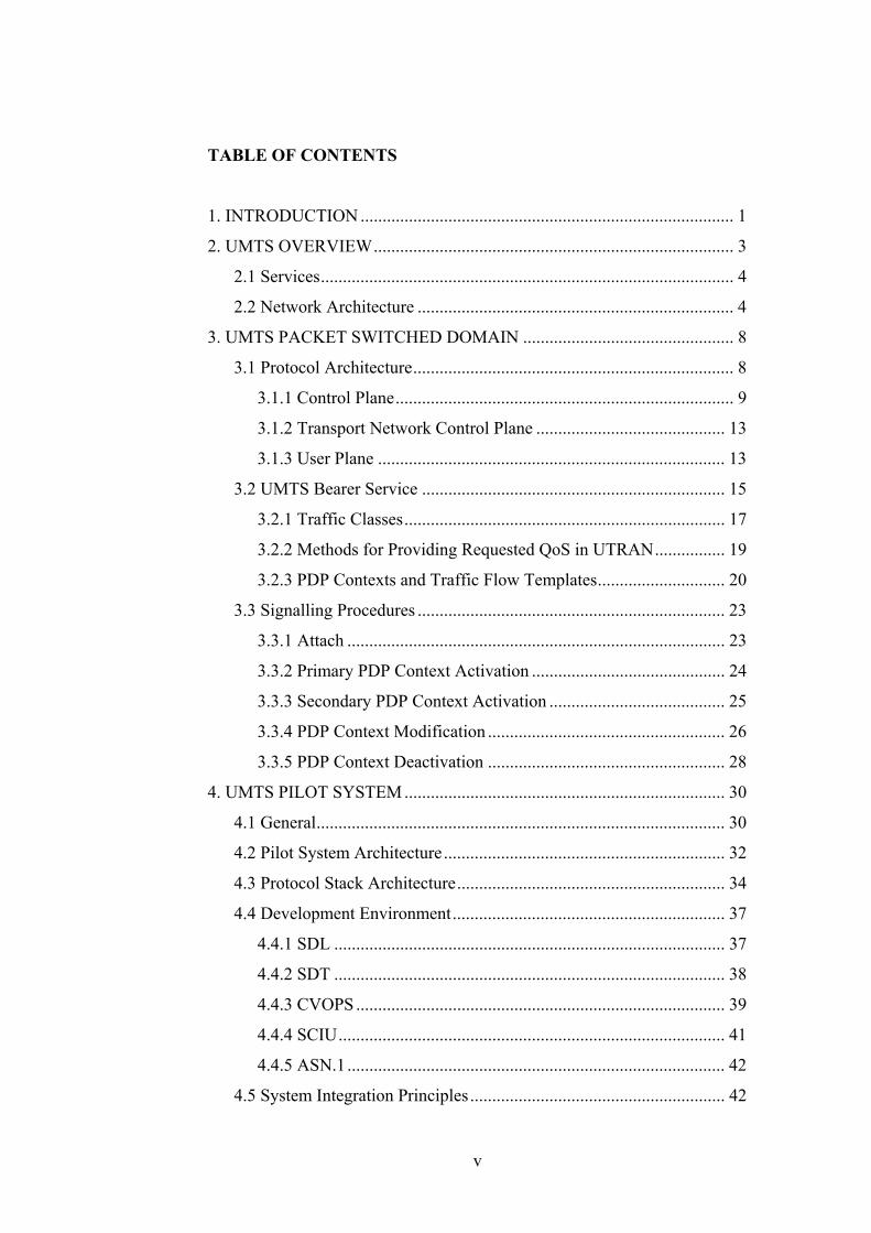
TABLE OF CONTENTS
1. INTRODUCTION ..................................................................................... 1
2. UMTS OVERVIEW.................................................................................. 3
2.1 Services.............................................................................................. 4
2.2 Network Architecture ........................................................................ 4
3. UMTS PACKET SWITCHED DOMAIN ................................................ 8
3.1 Protocol Architecture......................................................................... 8
3.1.1 Control Plane............................................................................. 9
3.1.2 Transport Network Control Plane ........................................... 13
3.1.3 User Plane ............................................................................... 13
3.2 UMTS Bearer Service ..................................................................... 15
3.2.1 Traffic Classes......................................................................... 17
3.2.2 Methods for Providing Requested QoS in UTRAN................ 19
3.2.3 PDP Contexts and Traffic Flow Templates............................. 20
3.3 Signalling Procedures ...................................................................... 23
3.3.1 Attach ...................................................................................... 23
3.3.2 Primary PDP Context Activation ............................................ 24
3.3.3 Secondary PDP Context Activation ........................................ 25
3.3.4 PDP Context Modification ...................................................... 26
3.3.5 PDP Context Deactivation ...................................................... 28
4. UMTS PILOT SYSTEM ......................................................................... 30
4.1 General............................................................................................. 30
4.2 Pilot System Architecture................................................................ 32
4.3 Protocol Stack Architecture............................................................. 34
4.4 Development Environment.............................................................. 37
4.4.1 SDL ......................................................................................... 37
4.4.2 SDT ......................................................................................... 38
4.4.3 CVOPS .................................................................................... 39
4.4.4 SCIU........................................................................................ 41
4.4.5 ASN.1...................................................................................... 42
4.5 System Integration Principles.......................................................... 42
v
4.6 PDCP Implementation..................................................................... 45
4.7 Interface to WCDMA Radio Parts................................................... 51
4.8 The Implementation of the QoS in the Pilot System ....................... 52
4.8.1 Packet Scheduling ................................................................... 52
4.8.2 Differentiated Service Marking............................................... 54
4.9 Interaction of the Application and Pilot System.............................. 55
4.10 Testing and Validation of the Protocol Implementations .............. 60
5. CONCLUSION ....................................................................................... 61
REFERENCES
APPENDIX 1: Protocol Stacks
vi
GLOSSARY
3G Third Generation
3GPP Third Generation Partnership Project
AAL2 ATM Adaptation Layer 2
AAL5 ATM Adaptation Layer 5
ALCAP Access Link Control Application Part
APN Access Point Name
ASN.1 Abstract Syntax Notation One
ATM Asynchronous Transfer Mode
BSC Base Station Controller
BSS Base Station System
BTS Base Transceiver Station
CN Core Network
CS Circuit Switched
CVOPS C-based Virtual OPerating System
DHCP Dynamic Host Configuration Protocol
DS Differentiated Service
DSCP Differentiated Service Code Point
EFSA Extended Finite State Automaton
EFSM Extended Finite State Machine
EIR Equipment Identity Register
FP Frame Protocol
GDB GNU Debugger
GGSN Gateway GPRS Support Node
GMM GPRS Mobility Management
GMSC Gateway Mobile Switching Center
GPRS General Packet Radio Service
GSM Global System for Mobile Communications
GTP-U GPRS Tunneling Protocol – User Plane
HLR Home Location Register
IP Internet Protocol
vii

ISDN Integrated Services Digital Network
ITU-T International Telecommunication Union, Telecommunication
Sector
MAC Medium Access Control
MSC Message Sequence Chart
MSC Mobile Switching Center
MT Mobile Terminal
MTP3B Message Transfer Part 3 Broadband
NBAP NodeB Application Part
NRC Nokia Research Center
PDCP Packet Data Convergence Protocol
PDN Packet Data Network
PDP Packet Data Protocol
PDU Protocol Data Unit
PER Packet Encoding Rule
PPP Point to Point Protocol
PS Packet Switched
PSTN Public Switched Telephone Network
P-TMSI Packet-Temporary Mobile Subscriber Identity
QoS Quality of Service
RAB Radio Access Bearer
RANAP Radio Access Network Application Part
RB Radio Bearer
RCS Revision Control System
RF Radio Frequency
RFC Request For Comments
RLC Radio Link Control
RNC Radio Network Controller
RNS Radio Network Subsystem
RNTI Radio Network Temporary Identity
ROHC RObust Header Compression
RRC Radio Resource Control
viii
RRM Radio Resource Management
RTP Real-time Transport Protocol
SAP Service Access Point
SCCP Signalling Connection Control Part
SCIU SDT CVOPS Integration Utility
SDL Specification and Description Language
SDL/GR SDL/Graphical Representation
SDL/PR SDL/Phrase Representation
SDT SDL Design Tool
SDU Service Data Unit
SGSN Serving GPRS Support Node
SM Session Management
SRNS Serving Radio Network Subsystem
SSCF Service-Specific Coordination Function
SSCOP Service-Specific Connection-Oriented Protocol
TCP Transmission Control Protocol
TE Terminal Equipment
TFT Traffic Flow Template
TI Transaction Identifier
TOS Type Of Service
UDP User Datagram Protocol
UE User Equipment
UMTS Universal Mobile Telecommunications System
UTRAN Universal Terrestrial Radio Access Network
VHE Virtual Home Environment
VME VERSAmodule Eurocard
VoIP Voice over IP
VTT Valtion Teknillinen Tutkimuskeskus (Technical Research
Centre of Finland)
WAP Wireless Application Protocol
WCDMA Wideband Code Division Multiple Access
ix
1. INTRODUCTION
During the last decade the number of the cellular phone subscribers has
grown enormously. Second generation (2G) systems, especially Global
System for Mobile Communications (GSM), has been a success story in the
mobile communications industry.
The Universal Mobile Telecommunication System (UMTS) is a Third
Generation (3G) system, introducing sophisticated packet data handling
capabilities such as high bit rates, and enables fast access to Internet. The
UMTS has also flexible Quality of Service (QoS) support, needed especially
in the packet switched domain.
3G brings along a lot of completely new technology compared to the 2G
systems, for example in radio interface the access technique is Wideband
Code Division Multiple Access (WCDMA). 3G contains a lot of new
features and enables users to have multiple concurrent applications. Thus
the protocols that set up the services are complicated. Development work of
the 3G systems is slow and it takes many years to have a real product at the
market. Pilot systems enable the demonstration of the system when the
product systems are still under development. Due to the fact that the
competition of equipment supplier contracts is hard, it is beneficial to be
able to demonstrate the know-how to possible customers.
This thesis was done as a part of a project where a UMTS Pilot system was
implemented. The Pilot system is based on the Third Generation Partnership
Project (3GPP) Release 99 specifications. It contains User Equipment (UE),
Universal Terrestrial Radio Access Network (UTRAN) and Core Network
(CN) emulators for the packet switched domain. System enables
connectivity to the real packet core network and also possibility to use real
WCDMA radio between UE and UTRAN. The aim of the project was to
build a 3G system for demonstration of its applications and behaviour of
1

applications over WCDMA radio. Also one target was to demonstrate the
functionality of the 3GPP protocols.
This thesis is divided into two parts, theoretical and practical. Chapter 2
gives an introduction to the UMTS and the services UMTS enables.
Evolution from the GSM system to UMTS is described in the same chapter.
Packet switched domain from the protocol architecture point of view is
described in chapter 3. Bearer Service concept and QoS issues are also
introduced in same chapter. At the end of the chapter some principal
signalling procedures are shown. In chapter 4 the practical part of the thesis
is depicted. It describes how the UMTS Pilot system was implemented. In
chapter 5 conclusions are made.
2
2. UMTS OVERVIEW
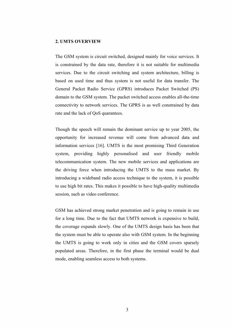
The GSM system is circuit switched, designed mainly for voice services. It
is constrained by the data rate, therefore it is not suitable for multimedia
services. Due to the circuit switching and system architecture, billing is
based on used time and thus system is not useful for data transfer. The
General Packet Radio Service (GPRS) introduces Packet Switched (PS)
domain to the GSM system. The packet switched access enables all-the-time
connectivity to network services. The GPRS is as well constrained by data
rate and the lack of QoS quarantees.
Though the speech will remain the dominant service up to year 2005, the
opportunity for increased revenue will come from advanced data and
information services [16]. UMTS is the most promising Third Generation
system, providing highly personalised and user friendly mobile
telecommunication system. The new mobile services and applications are
the driving force when introducing the UMTS to the mass market. By
introducing a wideband radio access technique to the system, it is possible
to use high bit rates. This makes it possible to have high-quality multimedia
session, such as video conference.
GSM has achieved strong market penetration and is going to remain in use
for a long time. Due to the fact that UMTS network is expensive to build,
the coverage expands slowly. One of the UMTS design basis has been that
the system must be able to operate also with GSM system. In the beginning
the UMTS is going to work only in cities and the GSM covers sparsely
populated areas. Therefore, in the first phase the terminal would be dual
mode, enabling seamless access to both systems.
3

2.1 Services
In the beginning, in 3GPP Release 99, UMTS network is going to provide at
least the same services as GSM. This means that from the end user point of
view those services behave similarly but their implementation within the
network is in many cases different than in GSM. In the later 3GPP Releases
(Release 4 and 5), handling of the services within the network will change.
[9] For example, circuit switched voice calls could be delivered as packet
switched calls (Voice over IP, VoIP).
UMTS contains a service creation environment which allows UMTS
operators and other entities create rapidly entirely new services [16]. These
services are, for example location based services. Location based services
are based on the mobile stations position. This enables a huge number of
different kind of applications, such as emergency services and traffic
information management. Virtual Home Environment (VHE) is a new
service concept. It enables users to feel that they are connected to the home
network even when roaming in other networks. VHE takes care that
subscribers' service information and profile are transferred between the
networks [9]. In the next chapter the packet data network architecture is
described in the point of view of network entity, considering also to the
evolution from the GSM to UMTS.
2.2 Network Architecture
UMTS is based largely on the GSM technology and the aim is to use as
much from GSM with GPRS extensions as possible [9]. Existing network
elements, such as Mobile Switching Center (MSC), Gateway GPRS Support
Node (GGSN) and Home Location Register (HLR), can be extended to
adopt the UMTS requirements, but some network elements must be
replaced. Following paragraphs describes how the evolution from the GSM
to UMTS is carried out.
4
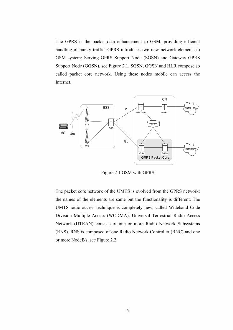
The GPRS is the packet data enhancement to GSM, providing efficient
handling of bursty traffic. GPRS introduces two new network elements to
GSM system: Serving GPRS Support Node (SGSN) and Gateway GPRS
Support Node (GGSN), see Figure 2.1. SGSN, GGSN and HLR compose so
called packet core network. Using these nodes mobile can access the
Internet.
PSTN, ISDN
INTERNET
GMSC
GGSN
CN
SGSN
HLR
Gb
A
Um
BTS
BTS
BSSMSC/VLR
BSC
GRPS Packet Core
MS
Figure 2.1 GSM with GPRS
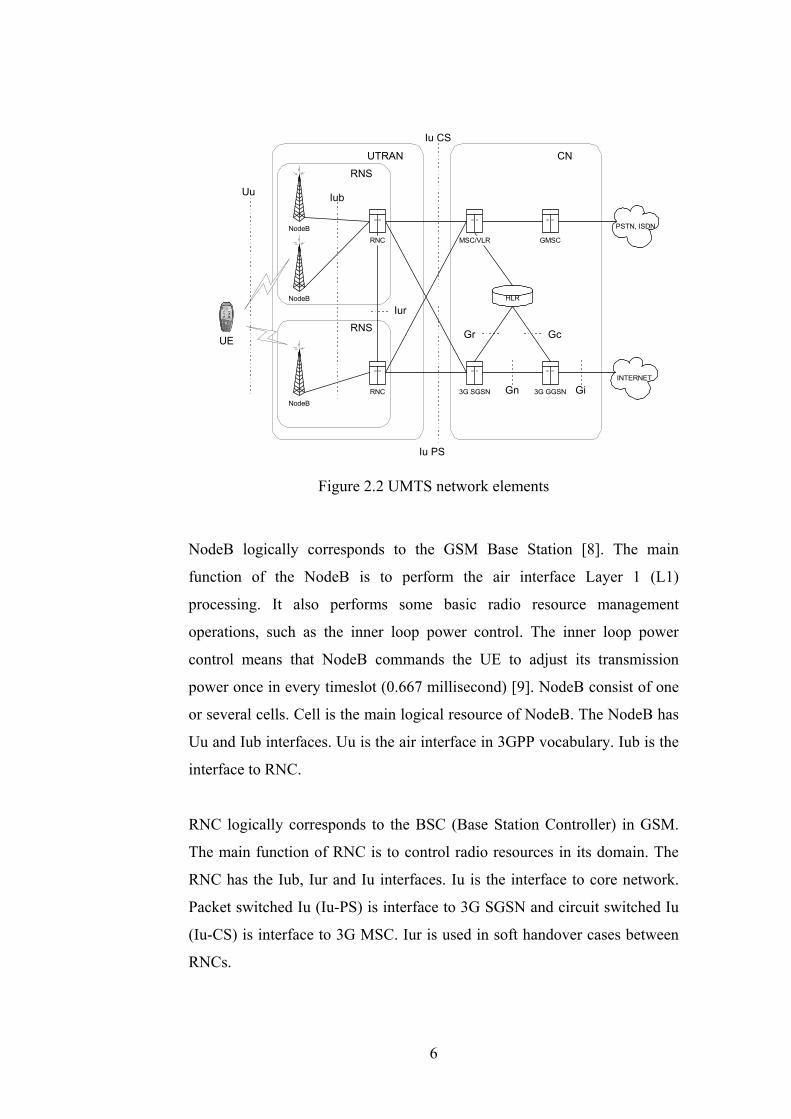
The packet core network of the UMTS is evolved from the GPRS network:
the names of the elements are same but the functionality is different. The
UMTS radio access technique is completely new, called Wideband Code
Division Multiple Access (WCDMA). Universal Terrestrial Radio Access
Network (UTRAN) consists of one or more Radio Network Subsystems
(RNS). RNS is composed of one Radio Network Controller (RNC) and one
or more NodeB's, see Figure 2.2.
5
RNS
PSTN, ISDN
INTERNET
NodeBRNC
UTRAN
GMSC
3G GGSN
CN
3G SGSN
HLR
Iu PS
Iu CS
Iur
IubUu
Gn Gi
Gr Gc
NodeB
NodeB
RNS
MSC/VLRRNC
UE
Figure 2.2 UMTS network elements
NodeB logically corresponds to the GSM Base Station [8]. The main
function of the NodeB is to perform the air interface Layer 1 (L1)
processing. It also performs some basic radio resource management
operations, such as the inner loop power control. The inner loop power
control means that NodeB commands the UE to adjust its transmission
power once in every timeslot (0.667 millisecond) [9]. NodeB consist of one
or several cells. Cell is the main logical resource of NodeB. The NodeB has
Uu and Iub interfaces. Uu is the air interface in 3GPP vocabulary. Iub is the
interface to RNC.
RNC logically corresponds to the BSC (Base Station Controller) in GSM.
The main function of RNC is to control radio resources in its domain. The
RNC has the Iub, Iur and Iu interfaces. Iu is the interface to core network.
Packet switched Iu (Iu-PS) is interface to 3G SGSN and circuit switched Iu
(Iu-CS) is interface to 3G MSC. Iur is used in soft handover cases between
RNCs.
6
Soft handover means that data is send and received via several cells of
NodeBs to UE. Set of cells through which the UE has simultaneously
connection to the UTRAN is called active set [9]. RNC and UE combines
incoming data from different NodeBs. The handover between GSM and
UMTS is called inter-system handover, which is always hard handover.
Hard handover means that the old connection to NodeB or BTS (Base
Transceiver Station) is released before new NodeB or BTS is started to use.
The main difference between 2G SGSN and 3G SGSN is that the Mobile
Management (MM) entity is divided between RNC and SGSN in 3G. This
means that changes in UTRAN are not necessary visible to the PS domain,
but RNC handles these situations. The SGSN is mainly responsible for MM
related issues like routing area update, location registration, packet paging
and controlling the security mechanisms related to the packet
communication. [9] The Iu-PS interface connects 3G SGSN to the RNC.
The GGSN maintains the connections towards other packet switched
networks, such as Internet [9]. It holds routing information of the UEs
connected to it. From the external network's point of view, GGSN acts as a
router, hiding the GPRS infrastructure from the external networks.
In UMTS the mobile terminal is called User Equipment (UE). The UE
interfaces the user and the Uu interface. It consist of the Mobile Equipment
(ME) and the Universal Subscriber Identity Module (USIM). USIM
contains data and procedures to identify the user. ME is a physical device
that sends and receives information over air interface.
HLR contains permanent subscribers information. The main functions of the
HLR are subscriber data and service handling, statistics and mobility
management [9]. The HLR of the GSM system can be used by modifying it
for UMTS purposes.
7
3. UMTS PACKET SWITCHED DOMAIN
The UMTS network consists of two main domains, packet switched and
circuit switched. In this chapter the packet switched domain is described
from protocol models point of view. UMTS bearer concept and traffic
classes are described and finally the most essential signalling procedures are
depicted.
3.1 Protocol Architecture
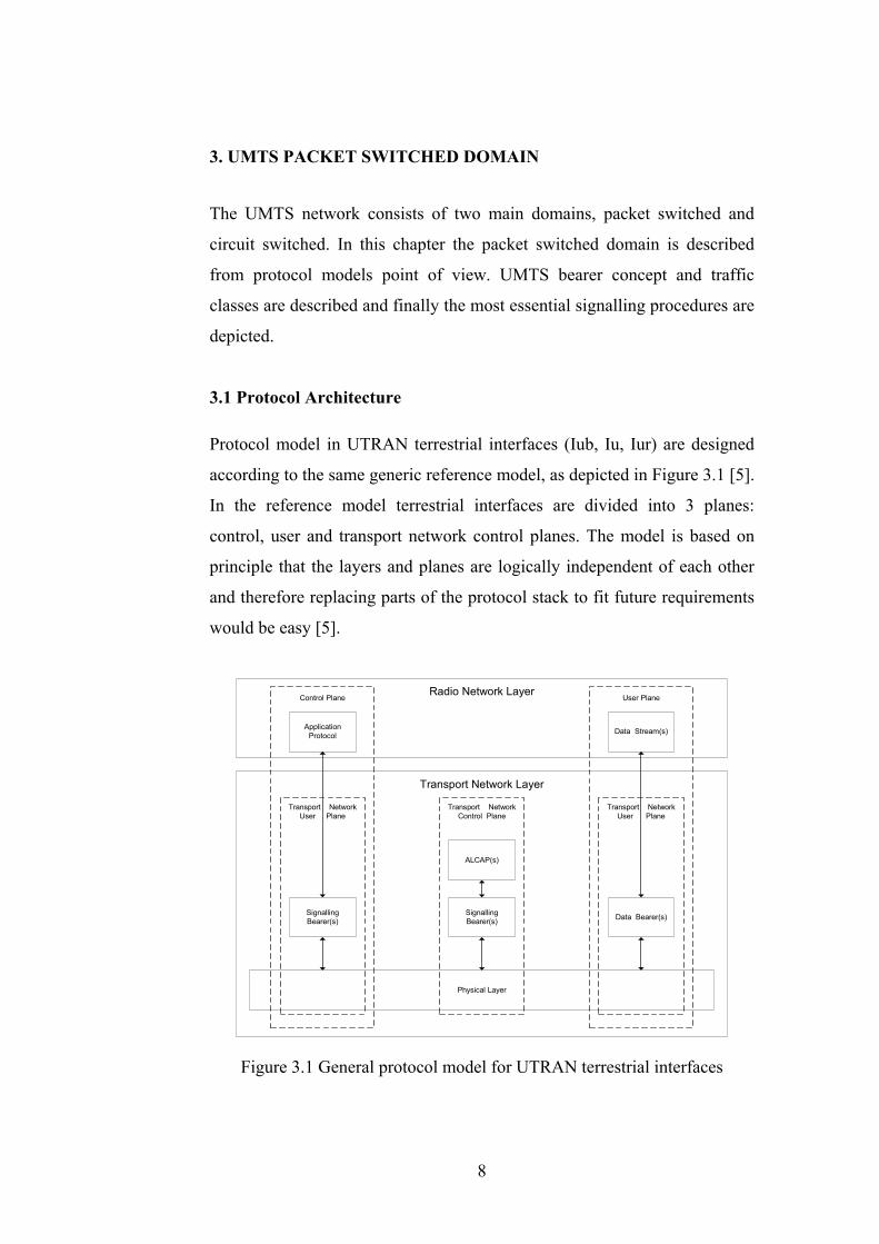
Protocol model in UTRAN terrestrial interfaces (Iub, Iu, Iur) are designed
according to the same generic reference model, as depicted in Figure 3.1 [5].
In the reference model terrestrial interfaces are divided into 3 planes:
control, user and transport network control planes. The model is based on
principle that the layers and planes are logically independent of each other
and therefore replacing parts of the protocol stack to fit future requirements
would be easy [5].
Physical Layer
SignallingBearer(s)
ApplicationProtocol
Data Bearer(s)SignallingBearer(s)
Data Stream(s)
ALCAP(s)
Transport NetworkUser Plane
Transport NetworkUser Plane
Transport NetworkControl Plane
Control Plane User PlaneRadio Network Layer
Transport Network Layer
Figure 3.1 General protocol model for UTRAN terrestrial interfaces
8
UTRAN related issues are visible in the Radio Network Layer. Radio
Network Layer consists of application protocols of the control plane and
Data Streams of the user plane. Main task of the application protocols is to
manage radio access bearers needed by data streams. Data streams are
characterised by one or more frame protocols specified for that interface [5].
Transport Network Layer takes care of conveying radio network layer
messages by setting and releasing signalling and data bearers.
Transport Network Control Plane includes Access Link Control Application
Part (ALCAP) protocol that is used to setup data bearers. ALCAP is generic
name for transport signalling protocol. If there are preconfigured data
bearers then ALCAP is not needed at all.
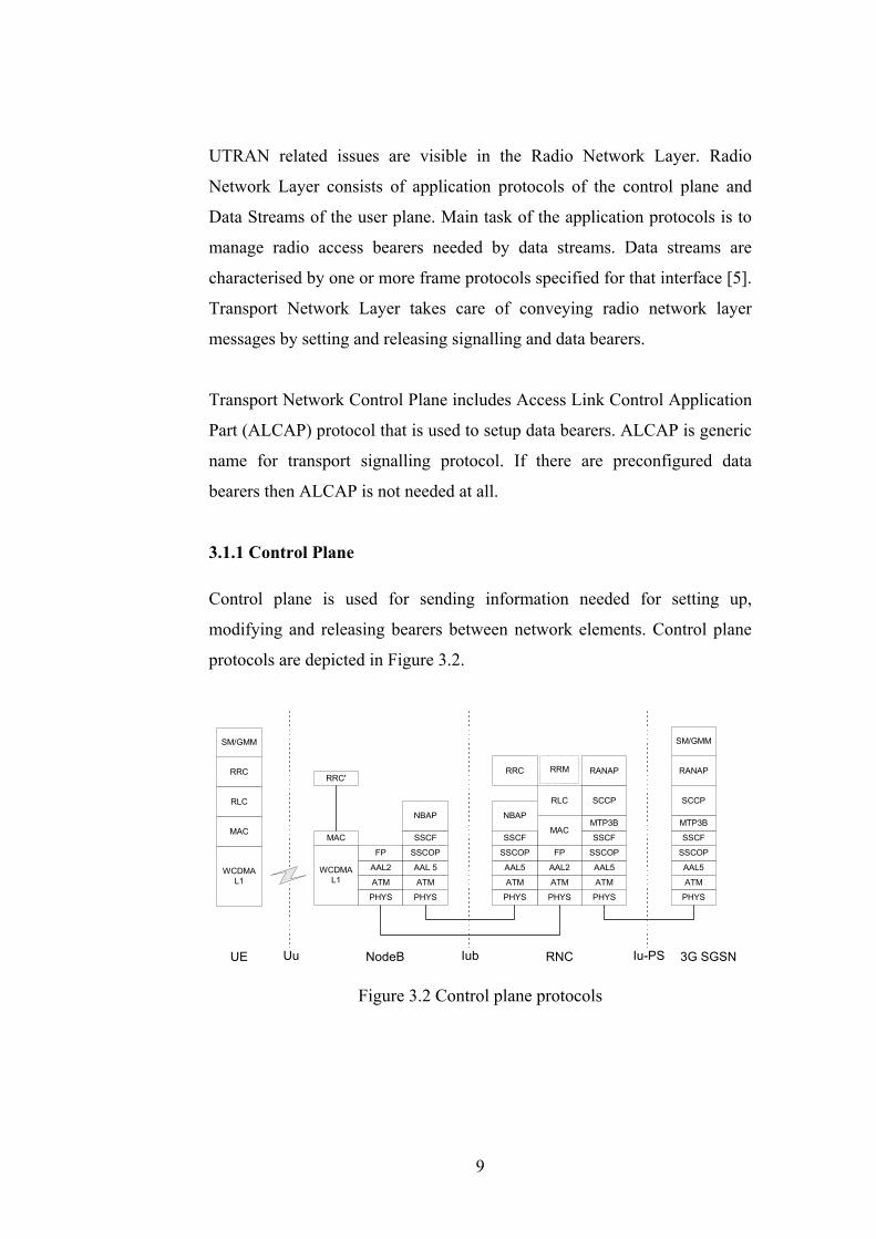
3.1.1 Control Plane
Control plane is used for sending information needed for setting up,
modifying and releasing bearers between network elements. Control plane
protocols are depicted in Figure 3.2.
RRC
RLC
MAC
WCDMAL1
WCDMAL1 ATM
NBAP
SM/GMM
UE NodeB RNC 3G SGSNUu Iub Iu-PS
PHYS
AAL2
PHYS
ATM
AAL2
FP FP
MAC
RLC
AAL5
ATM
PHYS
SCCP
AAL5
ATM
PHYSPHYS
ATM
AAL 5
RRC'RRC
SSCOP
SSCF
NBAP
SSCOP
SSCF
RRM RANAP
SCCP
PHYS
ATM
AAL5
SSCOP
SSCF
MTP3B
SSCOP
SSCF
MTP3B
RANAP
SM/GMM
MAC
Figure 3.2 Control plane protocols
9

Uu protocols
Session Management (SM) protocol is used to activate, modify and
deactivate packet data sessions. Its main function is to support Packet Data
Protocol (PDP) context handling of the user equipment [3]. SM contains
procedures for activating, modifying and deactivating PDP contexts. PDP
context activation, PDP context modification and PDP context deactivation
are described in chapter 3.3.
The main function of the GPRS Mobility Management (GMM) protocol is to
support mobility of the user terminals, for example, by location updates and
authentication. One of the main procedures of the GMM is Attach
procedure. This procedure is used to inform the network of the users
location and establishing GMM context to SGSN. The Attach procedure is
described in chapter 3.3.
The Radio Resource Control (RRC) is a signalling protocol between UE and
UTRAN. The RRC protocol can carry all higher layer (GMM/SM)
signalling as a payload of a message. It is used to setup and release the
signalling connection between UE and UTRAN. The signalling connection
setup must be performed before any higher layer signalling can be
transported. It is also used for setting up and releasing radio bearers for user
plane traffic. Radio bearer is presented in chapter 3.3. The subset of RRC in
NodeB (RRC') broadcasts cell-specific information or paging messages
from network to UE.
The Radio Link Control (RLC) protocol is used both in control and user
plane. It provides a logical link control over air interface. Main functions of
the RLC are for example, segmentation/reassembly, concatenation, error
detection, duplicate detection, retransmission and ciphering. RLC can
operate in three modes: transparent, unacknowledged and acknowledged.
Transparent mode means that the RLC does not add any protocol
information to SDUs (Service Data Unit). In unacknowledged mode RLC
10
transmits SDUs without guaranteeing delivery to the peer entity [9].
Acknowledged mode means that the RLC guarantees the transmission of
SDUs to peer entity.
The Medium Access Control (MAC) is also used both in control and in user
plane. It is responsible for controlling the communications over WCDMA
transport channels provided by physical layer [9]. MAC performs
scheduling of radio bearers (or logical channels). This is depicted more
closely in chapter 4.8.1.
Iub protocols
The radio specific information is told to base station with NodeB
Application Part (NBAP) protocol. NBAP is used to setup and release radio
channels and then bind established resources to radio interface. NBAP is
also used for configuring cells of base stations.
Frame Protocol (FP) is used to transfer data streams over AAL 2. Payload
of FP usually contains one or more MAC PDU's (Protocol Data Units) and
FP header contains synchronisation information between NodeB and RNC.
Iu protocols
Radio Access Network Application Part (RANAP) controls the resources in
the Iu interface. In PS domain it is between RNC and 3G SGSN and in CS
domain between RNC and 3G MSC. It provides Radio Access Bearer
(RAB) management, by providing means for CN to control the
establishment, modification and release of RABs between UE and CN. It
also participates user mobility, by transferring a RAB to a new RNS when a
user moves from the area of the serving RNS to another. [9] This service is
called SRNS relocation. RANAP also transfers higher layer messages
between UE and 3G SGSN (in PS domain), as the RRC transfers UE
messages to RNC, RANAP transfers them from RNC to 3G SGSN.
11
Message Transfer Part Level 3 Broadband (MTP3B) and Signalling
Connection Control Part (SCCP) belong to the Common Channel
Signalling System 7 (SS7) protocol stack inherited from the GSM system.
The purpose of SCCP is to provide connection-oriented and connectionless
services. MTP3B is responsible for message routing.
Others
Radio Resource Management (RRM) is actually not a protocol, it is rather a
collection of algorithms needed for establishing and maintaining a good
radio path. The RRM contains algorithms for handovers, power control,
admission control, load control and packet scheduling. The packet scheduler
is discussed more detailed in chapter 4.8.1 because it is an essential part of
the Pilot system.
Asynchronous Transfer Mode (ATM) transmission is based on fixed length
data frames, cells. Length of the cell is 53 bytes, from which the 5 first bytes
are for the header and following 48 bytes are for payload.
ATM Adaptation Layer (AAL) 2 and AAL 5 are adaptation layers to the
ATM. The main task of those layers is to split data to the ATM cells.
Characteristics of the AAL 2 is a short payload, which reduces the delay of
packetisation. Therefore it is suitable for carrying for example speech
packets.
Service-Specific Connection-Oriented Protocol (SSCOP) provides
mechanisms for the establishment, release and monitoring of signalling
information exchanged between peer entities. It provides assured data
delivery between connection endpoints. Service-Specific Coordination
Function (SSCF) maps the SSCOP to the upper layer.
12
3.1.2 Transport Network Control Plane
Transport Network Control Plane exists only in Iu-CS, Iur and Iub
interfaces. Because Iur and CS have not been implemented in Pilot system
those are out of the scope of the thesis, so only Transport Network Control
Plane in Iub is described here. The Iu-PS uses preconfigured AAL 5
connections, ALCAP is not needed. Transport Network Control Plane is
present only when transport technology needs controlling.
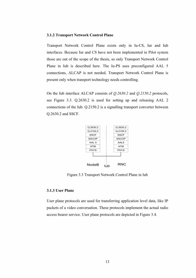
On the Iub interface ALCAP consists of Q.2630.2 and Q.2150.2 protocols,
see Figure 3.3. Q.2630.2 is used for setting up and releasing AAL 2
connections of the Iub. Q.2150.2 is a signalling transport converter between
Q.2630.2 and SSCF.
NodeB Iub
AAL5
ATM
PHYSPHYS
ATM
AAL 5
SSCOP
SSCF
SSCOP
SSCF
RNC
Q.2150.2
Q.2630.2
Q.2150.2
Q.2630.2
Figure 3.3 Transport Network Control Plane in Iub
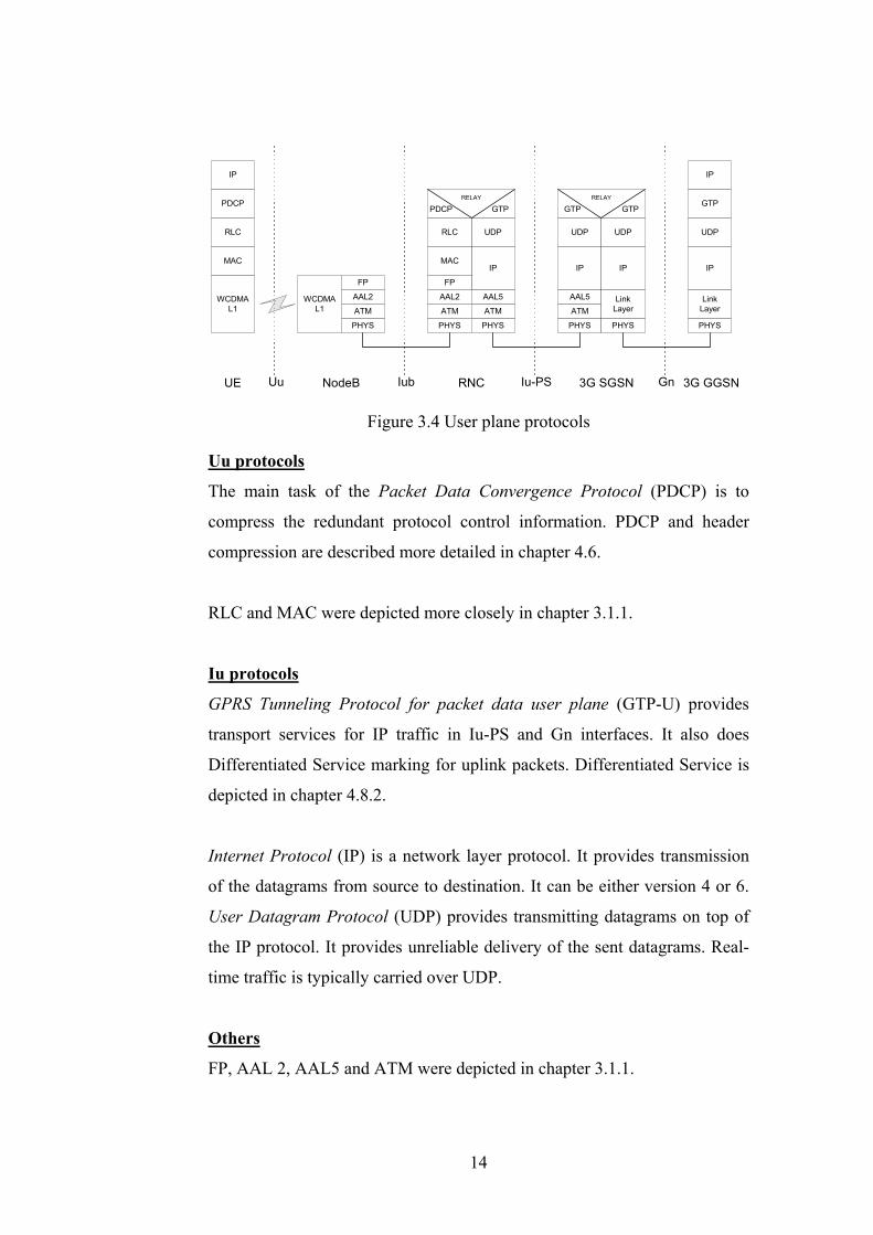
3.1.3 User Plane
User plane protocols are used for transferring application level data, like IP
packets of a video conversation. These protocols implement the actual radio
access bearer service. User plane protocols are depicted in Figure 3.4.
13
PDCP
RLC
MAC
WCDMAL1
WCDMAL1 ATM
UDP
IP
IP
GTP
UDP
IP
IP
UE NodeB RNC 3G SGSN 3G GGSN
PHYS
AAL2
PHYS
ATM
AAL2
FP FP
MAC
RLC
AAL5
ATM
PHYS
UDP
IP
AAL5
ATM
PHYS
UDP
IP
LinkLayer
PHYS
LinkLayer
PHYS
RELAY
PDCP GTPRELAY
GTP GTP
Uu Iub Iu-PS Gn
Figure 3.4 User plane protocols
Uu protocols
The main task of the Packet Data Convergence Protocol (PDCP) is to
compress the redundant protocol control information. PDCP and header
compression are described more detailed in chapter 4.6.
RLC and MAC were depicted more closely in chapter 3.1.1.
Iu protocols
GPRS Tunneling Protocol for packet data user plane (GTP-U) provides
transport services for IP traffic in Iu-PS and Gn interfaces. It also does
Differentiated Service marking for uplink packets. Differentiated Service is
depicted in chapter 4.8.2.
Internet Protocol (IP) is a network layer protocol. It provides transmission
of the datagrams from source to destination. It can be either version 4 or 6.
User Datagram Protocol (UDP) provides transmitting datagrams on top of
the IP protocol. It provides unreliable delivery of the sent datagrams. Real-
time traffic is typically carried over UDP.
Others
FP, AAL 2, AAL5 and ATM were depicted in chapter 3.1.1.
14
3.2 UMTS Bearer Service
A typical end-user is not interested in how a certain service is technically
provided, rather the user observes quality of the service. Quality usually
means for example accessibility to the service and the delay of the
connection. Bit rate is as well a significant factor when measuring the
quality of a service.
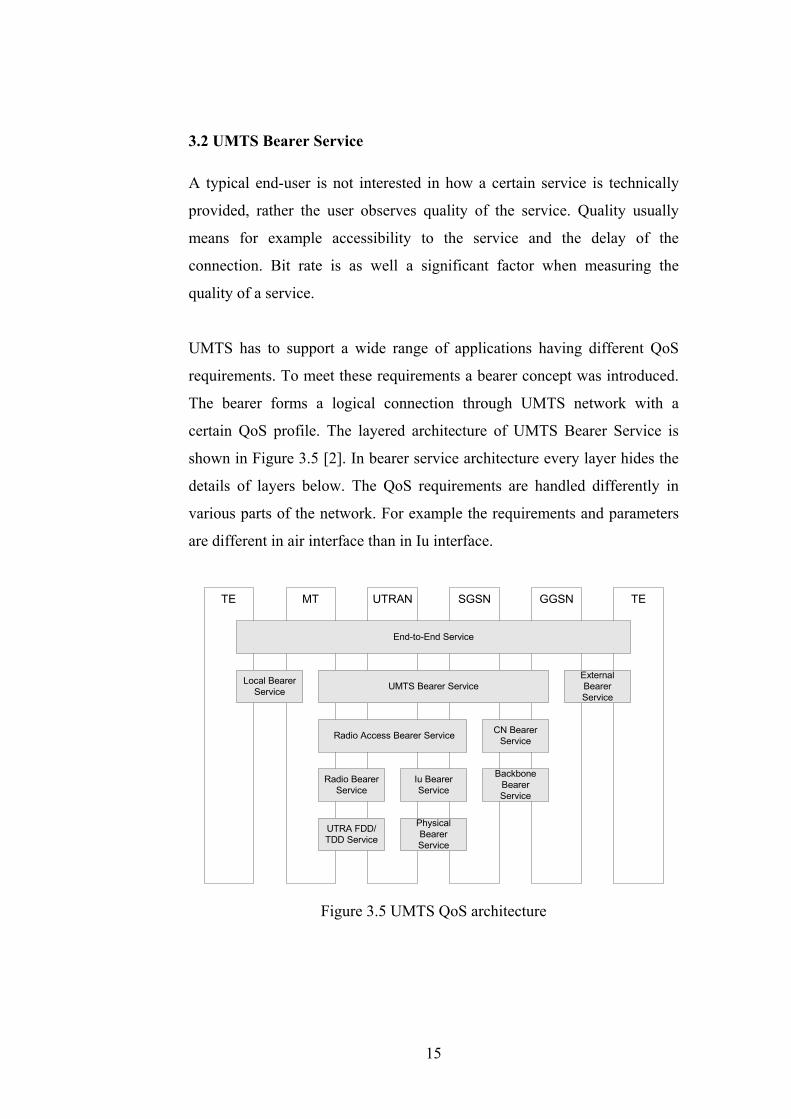
UMTS has to support a wide range of applications having different QoS
requirements. To meet these requirements a bearer concept was introduced.
The bearer forms a logical connection through UMTS network with a
certain QoS profile. The layered architecture of UMTS Bearer Service is
shown in Figure 3.5 [2]. In bearer service architecture every layer hides the
details of layers below. The QoS requirements are handled differently in
various parts of the network. For example the requirements and parameters
are different in air interface than in Iu interface.
TE MT UTRAN SGSN GGSN TE
End-to-End Service
Local BearerService UMTS Bearer Service
ExternalBearerService
Radio Access Bearer Service CN BearerService
Radio BearerService
Iu BearerService
BackboneBearerService
UTRA FDD/TDD Service
PhysicalBearerService
Figure 3.5 UMTS QoS architecture
15

Network services are considered to be end-to-end, between Terminal
Equipment's (TE), with a certain QoS profile. The End-to-End Service uses
services from Local Bearer Service, UMTS Bearer Service and External
Bearer Service. The UMTS Bearer Service in turn uses Radio Access Bearer
Service and CN Bearer Service to fulfill its QoS requirements. All the
Bearer Services have a set of attributes representing their capabilities. The
attributes of the UMTS Bearer Service are described in Table 1. [2].
Traffic Class Conversational Streaming Interactive Background
Maximum bit rate X X X X
Delivery order X X X X
Maximum SDU size X X X X
SDU format information X X
SDU error ratio X X X X
Residual bit error ratio X X X X
Delivery of erroneous SDUs X X X X
Transfer delay X X
Guaranteed bit rate X X
Traffic handling priority X
Allocation/retention priority X X X X
Table 1 UMTS Bearer service parameters
Here is a short description of each attribute [2]:
• Traffic class indicates for what kind of application the bearer is suitable.
Traffic class is discussed in a more detailed way in chapter 3.2.1.
• Maximum bit rate, maximum number of bits delivered (kbits/s).
• Delivery order indicates whether the UMTS bearer shall provide in-
sequence SDU delivery or not.
• Maximum SDU size indicates the maximum allowed SDU size. It is
used for admission control and policing.
• SDU format information, list of possible exact sizes of SDUs. UTRAN
needs SDU size information to be able to operate in transparent RLC
16
protocol mode, which is beneficial to spectral efficiency and delay when
RLC re-transmission is not used. Thus, if the application can specify
SDU sizes, the bearer is less expensive.
• SDU error ratio indicates the fraction of lost or erroneous SDUs.
• Residual bit error ratio indicates the undetected bit error ratio in the
delivered SDUs. If no error detection is requested, Residual bit error
ratio indicates the bit error ratio in the delivered SDUs.
• Delivery of erroneous SDUs indicates whether SDUs detected as
erroneous shall be delivered or discarded.
• Transfer Delay indicates the maximum delay accepted for sending the
message to receiver.
• Guaranteed bit rate, guaranteed number of bits delivered (kbits/s).
Guaranteed bit rate may be used to facilitate admission control based on
available resources.
• Traffic Handling Priority (THP) specifies the relative importance for
handling of all SDUs belonging to the UMTS bearer compared to the
SDUs of other bearers. THP is used only in case of interactive traffic
class.
• Allocation/retention priority specifies the relative importance compared
to other UMTS bearers for allocation and retention of the UMTS bearer.
3.2.1 Traffic Classes
The UMTS QoS is based on the classification of different kind of traffic
flows. The classification has to be robust and capable of providing
reasonable QoS resolution [2]. Four different QoS classes has been defined:
• Conversational class
• Streaming class
• Interactive class
• Background class
17
The main distinguishing factor between these QoS classes is how delay
sensitive the traffic is: Conversational class is meant for traffic which is
very delay sensitive while background class is the most delay insensitive
traffic class [2].
The conversational class is intended to be used to carry real-time, delay
sensitive traffic flows. The best known application of this class is speech
over circuit-switched bearers. Video telephony belongs to this category too.
Maximum transfer delay is given by the human perception and hence limit
for acceptable transfer delay is very strict, as a failure to provide it will
result in unacceptable lack of quality.
Streaming class is also intended to carry real-time traffic flow, difference to
the conversational class is that the traffic is not so delay sensitive. Streaming
applications, like television channel downloading, are very asymmetric and
therefore typically withstand more delay than more symmetric
conversational services. This also means that they tolerate more jitter in
transmission.
Interactive scheme applies when the end-user is on line requesting data from
a server, for example web browsing and database retrieval. Because end-
user is expecting the message (response) within a certain time, the round trip
delay time is therefore one of the key attributes.
Background traffic is characterised by that the destination is not expecting
the data within a certain time. Examples of the background applications are
emails, Short Message Service, download of databases and reception of
measurement records [2].
18
3.2.2 Methods for Providing Requested QoS in UTRAN
Radio interface has limited bandwidth, and increasing that is very difficult.
Thus, it is necessary to use it efficiently. Some methods are designed to be
used especially in error prone air interface. The RRM in RNC is mainly
responsible for these methods. RRM contains various algorithms, which aim
to stabilise the radio path enabling it to fulfill the QoS criteria set by the
service using the radio path [9]. Those algorithms are, for example power
control, load control, handover control, admission control and packet
scheduling.
When real-time multimedia traffic is transferred over a limited bandwidth
radiolink, it is necessary to reduce the overhead that results from
transmitting the headers [13]. RRM can reduce the overhead by choosing
some IP header compression algorithm (supported by the UE). Two
different algoritms have been specified by 3GPP, RFC 2507 (Release 99)
and RFC 3095 (Release 4). Latter is also known as RObust Header
Compression (ROHC).
The user plane of the UMTS core network is based on IP, therefore it is
necessary to have QoS provision for IP traffic. Differentiated Services
method is the IP level QoS provision mechanism 3GPP has specified in
UMTS Release 99.
Packet scheduling, header compression (ROHC) and Differentiated Service
Marking are implemented to the Pilot system and therefore those are
described in a more detailed way in chapters 4.8.1, 4.6 and 4.8.2
respectively.
19
3.2.3 PDP Contexts and Traffic Flow Templates
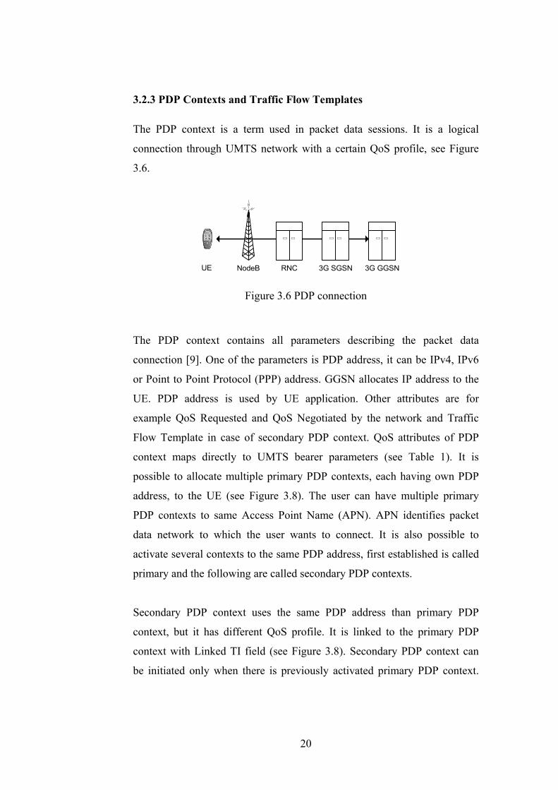
The PDP context is a term used in packet data sessions. It is a logical
connection through UMTS network with a certain QoS profile, see Figure
3.6.
UE RNCNodeB 3G SGSN 3G GGSN
Figure 3.6 PDP connection
The PDP context contains all parameters describing the packet data
connection [9]. One of the parameters is PDP address, it can be IPv4, IPv6
or Point to Point Protocol (PPP) address. GGSN allocates IP address to the
UE. PDP address is used by UE application. Other attributes are for
example QoS Requested and QoS Negotiated by the network and Traffic
Flow Template in case of secondary PDP context. QoS attributes of PDP
context maps directly to UMTS bearer parameters (see Table 1). It is
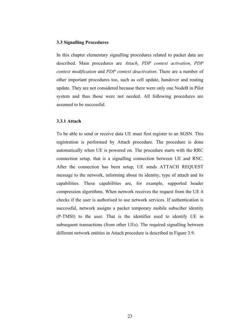
possible to allocate multiple primary PDP contexts, each having own PDP
address, to the UE (see Figure 3.8). The user can have multiple primary
PDP contexts to same Access Point Name (APN). APN identifies packet
data network to which the user wants to connect. It is also possible to
activate several contexts to the same PDP address, first established is called
primary and the following are called secondary PDP contexts.
Secondary PDP context uses the same PDP address than primary PDP
context, but it has different QoS profile. It is linked to the primary PDP
context with Linked TI field (see Figure 3.8). Secondary PDP context can
be initiated only when there is previously activated primary PDP context.
20
Primary PDP context is used for transmitting data that does not fit any of the
packet filters. Packet filter is described in the next paragraph.
Traffic Flow Template (TFT) consists of from one to eight packet filters,
which are used to route the data packets to the right PDP contexts, see
Figure 3.8. This information element is signalled to GGSN with the PDP
context activation or modification procedure. It is also signalled to UE in
case the UE terminates context activation or modification. Traffic Flow
Template is used in case of secondary PDP context. A packet filter has also
an evaluation precedence index that indicates the order of the evaluation in
case of multiple filters. The UE (or network) needs to attach unambiguous
TFT all except one PDP context to enable correct routing of the data.
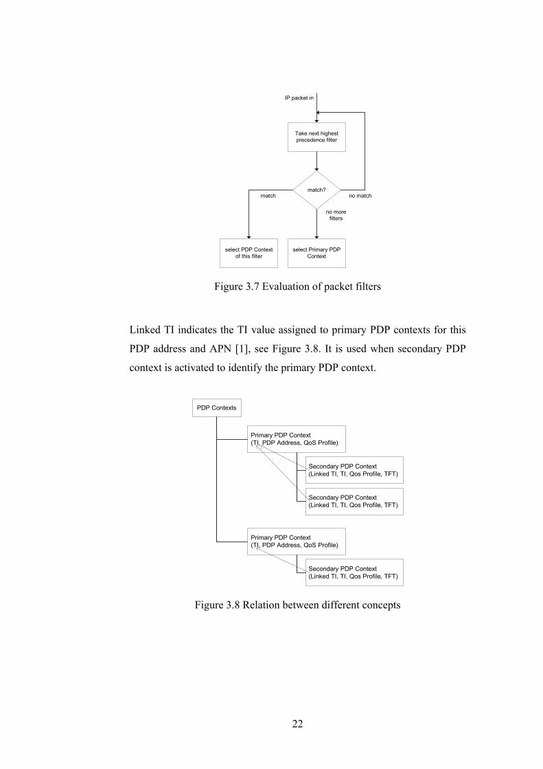
When PDP context has been created and it is time to send application level
data, such as VoIP packets, the right radio bearer is determined first. This is
done by evaluating the filters in the traffic flow template in order of the
evaluation precedence. If IP packet matches to the filter, then it can be
routed to that bearer. Filtering can be based on various fields in the packet
header, for example, IP addresses, next protocol, UDP/Transmission
Control Protocol (TCP) port numbers and so on. If a filter is not found (or
matching) packet is sent to PDP context that does not have filter (normally
primary PDP context). Figure 3.7. describes the evaluation of the filters.
21
Take next highestprecedence filter
match?
select PDP Contextof this filter
select Primary PDPContext
IP packet in
no match
no morefilters
match
Figure 3.7 Evaluation of packet filters
Linked TI indicates the TI value assigned to primary PDP contexts for this
PDP address and APN [1], see Figure 3.8. It is used when secondary PDP
context is activated to identify the primary PDP context.
Primary PDP Context(TI, PDP Address, QoS Profile)
Secondary PDP Context(Linked TI, TI, Qos Profile, TFT)
Primary PDP Context(TI, PDP Address, QoS Profile)
Secondary PDP Context(Linked TI, TI, Qos Profile, TFT)
Secondary PDP Context(Linked TI, TI, Qos Profile, TFT)
PDP Contexts
Figure 3.8 Relation between different concepts
22
3.3 Signalling Procedures
In this chapter elementary signalling procedures related to packet data are
described. Main procedures are Attach, PDP context activation, PDP
context modification and PDP context deactivation. There are a number of
other important procedures too, such as cell update, handover and routing
update. They are not considered because there were only one NodeB in Pilot
system and thus those were not needed. All following procedures are
assumed to be successful.
3.3.1 Attach
To be able to send or receive data UE must first register to an SGSN. This
registration is performed by Attach procedure. The procedure is done
automatically when UE is powered on. The procedure starts with the RRC
connection setup, that is a signalling connection between UE and RNC.
After the connection has been setup, UE sends ATTACH REQUEST
message to the network, informing about its identity, type of attach and its
capabilities. These capabilities are, for example, supported header
compression algorithms. When network receives the request from the UE it
checks if the user is authorised to use network services. If authentication is
successful, network assigns a packet temporary mobile subsciber identity
(P-TMSI) to the user. That is the identifier used to identify UE in
subsequent transactions (from other UEs). The required signalling between
different network entities in Attach procedure is described in Figure 3.9.
23

RRC:RRC_CONNECTION_REQUEST
NBAP:RADIOLINK_SETUP
NBAP:RADIOLINK_SETUP_RESPONSE
SGSNRNCNodeBUE
RRC:RRC_CONNECTION_SETUP
RRC:RRC_CONNECTION_SETUP_COMPLETE
NBAP:SYNCRONIZATION_INDICATION
RRC:INITIAL_DIRECT_TRANSFER(GMM_ATTACH) RANAP:INITIAL_UE_MESSAGE
(GMM_ATTACH)
RANAP:SECURITY_MODE_COMMANDRRC:SECURITY_MODE_COMMAND
RRC:SECURITY_MODE_COMPLETERANAP:SECURITY_MODE_COMPLETE
RANAP:DIRECT_TRANSFER(GMM_ATTACH_ACCEPT)RRC:DOWNLINK_DIRECT_TRANSFER
(GMM_ATTACH_ACCEPT)
RRC:UPLINK_DIRECT_TRANSFER(GMM_ATTACH_COMPLETE) RANAP:DIRECT_TRANSFER
(GMM_ATTACH_COMPLETE)
RANAP:DIRECT_TRANSFER(GMM_AUTHENTICATION_REQUEST)
RRC:DOWNLINK_DIRECT_TRANSFER(GMM_AUTHENTICATION_REQUEST)
RRC:UPLINK_DIRECT_TRANSFER(GMM_AUTHENTICATION_RESPONSE)
RANAP:DIRECT_TRANSFER(GMM_AUTHENTICATION_RESPONSE)
Figure 3.9 Attach procedure
3.3.2 Primary PDP Context Activation
If the UE wants to exchange data packets with the external packet data
network (PDN) after a successful Attach procedure it needs to have a PDP
address used in that PDN. The PDP context activation procedure is shown in
Figure 3.10. It starts when the UE sends an ACTIVATE PDP CONTEXT
REQUEST message to the network. The message contains, for example,
PDP type (IPv4 or IPv6) and requested QoS. If IP address field is left
empty, then dynamic addressing is used and the GGSN allocates an address
for UE. After SGSN has received the message, Bearer Setup procedures are
started, Radio Bearer (RB) is setup between UE and RNC and Iu Bearer is
setup between RNC and SGSN. These two bearers compose Radio Access
Bearer (RAB) with the requested QoS parameters, see Figure 3.5. SGSN
informs GGSN about the new context by sending CREATE PDP
CONTEXT REQUEST message. GGSN uses information in this message to
create a new entry for its PDP context table and it responds to SGSN with
24
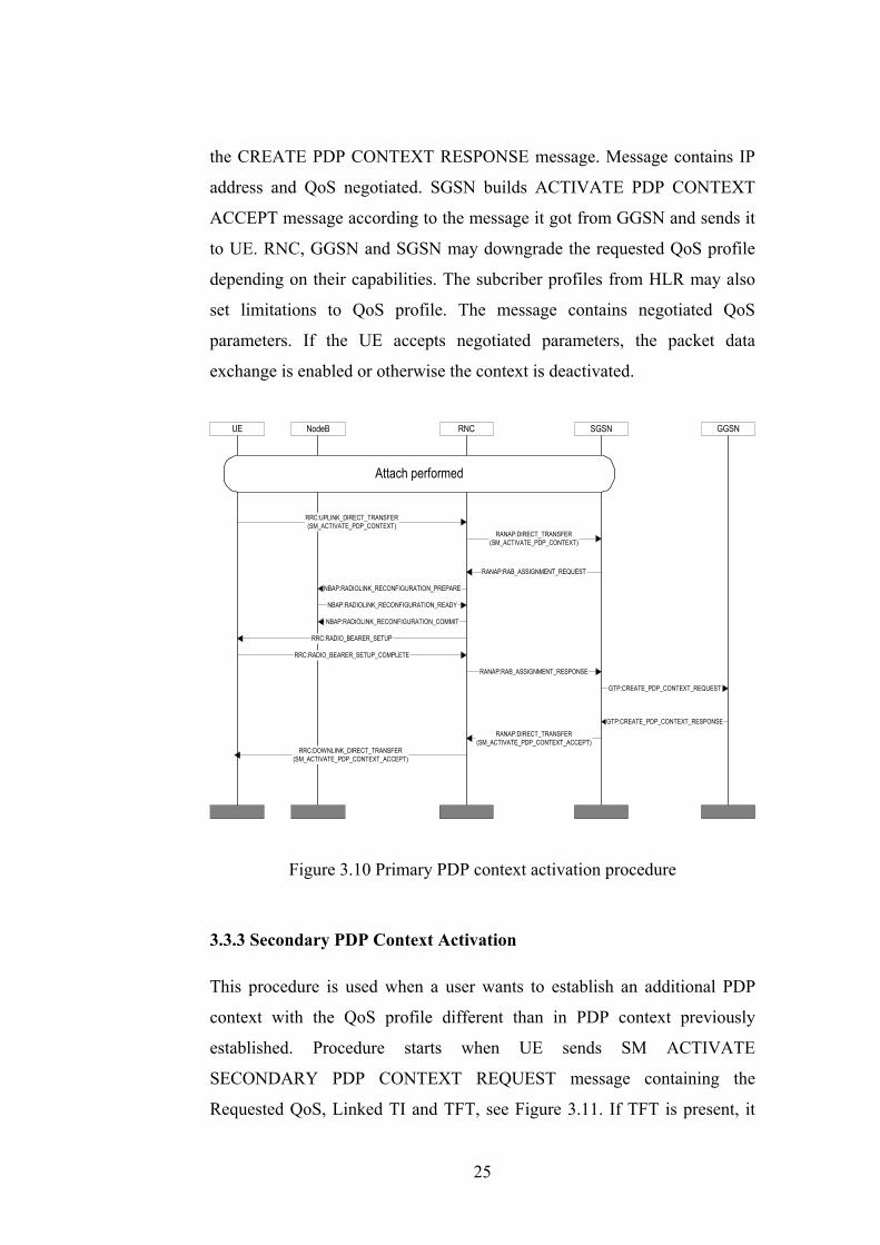
the CREATE PDP CONTEXT RESPONSE message. Message contains IP
address and QoS negotiated. SGSN builds ACTIVATE PDP CONTEXT
ACCEPT message according to the message it got from GGSN and sends it
to UE. RNC, GGSN and SGSN may downgrade the requested QoS profile
depending on their capabilities. The subcriber profiles from HLR may also
set limitations to QoS profile. The message contains negotiated QoS
parameters. If the UE accepts negotiated parameters, the packet data
exchange is enabled or otherwise the context is deactivated.
SGSNRNCNodeBUE
RANAP:RAB_ASSIGNMENT_REQUEST
RRC:RADIO_BEARER_SETUP
RRC:UPLINK_DIRECT_TRANSFER(SM_ACTIVATE_PDP_CONTEXT)
RANAP:DIRECT_TRANSFER(SM_ACTIVATE_PDP_CONTEXT)
Attach performed
NBAP:RADIOLINK_RECONFIGURATION_PREPARE
NBAP:RADIOLINK_RECONFIGURATION_READY
NBAP:RADIOLINK_RECONFIGURATION_COMMIT
RRC:RADIO_BEARER_SETUP_COMPLETE
RANAP:RAB_ASSIGNMENT_RESPONSE
GGSN
GTP:CREATE_PDP_CONTEXT_REQUEST
GTP:CREATE_PDP_CONTEXT_RESPONSE
RANAP:DIRECT_TRANSFER(SM_ACTIVATE_PDP_CONTEXT_ACCEPT)
RRC:DOWNLINK_DIRECT_TRANSFER(SM_ACTIVATE_PDP_CONTEXT_ACCEPT)
Figure 3.10 Primary PDP context activation procedure
3.3.3 Secondary PDP Context Activation
This procedure is used when a user wants to establish an additional PDP
context with the QoS profile different than in PDP context previously
established. Procedure starts when UE sends SM ACTIVATE
SECONDARY PDP CONTEXT REQUEST message containing the
Requested QoS, Linked TI and TFT, see Figure 3.11. If TFT is present, it
25
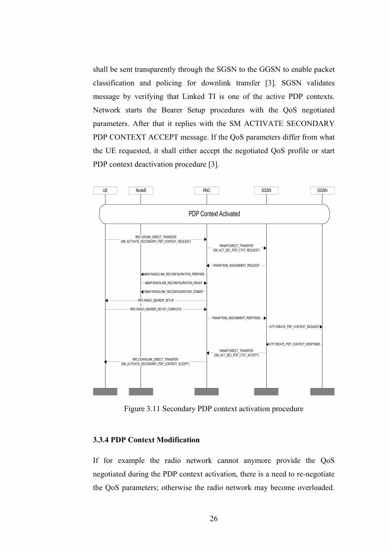
shall be sent transparently through the SGSN to the GGSN to enable packet
classification and policing for downlink transfer [3]. SGSN validates
message by verifying that Linked TI is one of the active PDP contexts.
Network starts the Bearer Setup procedures with the QoS negotiated
parameters. After that it replies with the SM ACTIVATE SECONDARY
PDP CONTEXT ACCEPT message. If the QoS parameters differ from what
the UE requested, it shall either accept the negotiated QoS profile or start
PDP context deactivation procedure [3].
SGSNRNCNodeBUE
RANAP:RAB_ASSIGNMENT_REQUEST
RRC:RADIO_BEARER_SETUP
RRC:UPLINK_DIRECT_TRANSFER(SM_ACTIVATE_SECONDARY_PDP_CONTEXT_REQUEST)
RANAP:DIRECT_TRANSFER(SM_ACT_SEC_PDP_CTXT_REQUEST)
PDP Context Activated
NBAP:RADIOLINK_RECONFIGURATION_PREPARE
NBAP:RADIOLINK_RECONFIGURATION_READY
NBAP:RADIOLINK_RECONFIGURATION_COMMIT
RRC:RADIO_BEARER_SETUP_COMPLETE
RANAP:RAB_ASSIGNMENT_RESPONSE
GGSN
GTP:CREATE_PDP_CONTEXT_REQUEST
GTP:CREATE_PDP_CONTEXT_RESPONSE
RANAP:DIRECT_TRANSFER(SM_ACT_SEC_PDP_CTXT_ACCEPT)
RRC:DOWNLINK_DIRECT_TRANSFER(SM_ACTIVATE_SECONDARY_PDP_CONTEXT_ACCEPT)
Figure 3.11 Secondary PDP context activation procedure
3.3.4 PDP Context Modification
If for example the radio network cannot anymore provide the QoS
negotiated during the PDP context activation, there is a need to re-negotiate
the QoS parameters; otherwise the radio network may become overloaded.
26
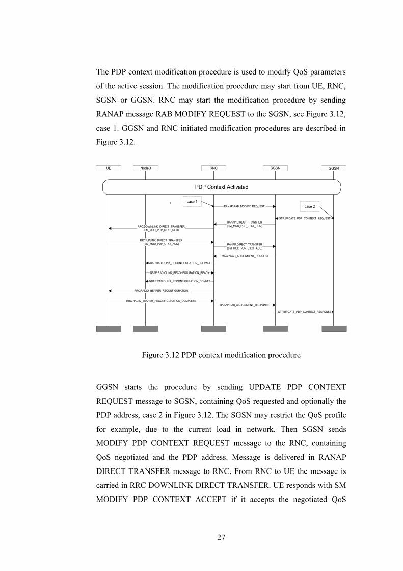
The PDP context modification procedure is used to modify QoS parameters
of the active session. The modification procedure may start from UE, RNC,
SGSN or GGSN. RNC may start the modification procedure by sending
RANAP message RAB MODIFY REQUEST to the SGSN, see Figure 3.12,
case 1. GGSN and RNC initiated modification procedures are described in
Figure 3.12.
SGSNRNCNodeBUE
RANAP:RAB_ASSIGNMENT_REQUEST
RRC:RADIO_BEARER_RECONFIGURATION
RRC:DOWNLINK_DIRECT_TRANSFER(SM_MOD_PDP_CTXT_REQ)
RANAP:DIRECT_TRANSFER(SM_MOD_PDP_CTXT_REQ)
PDP Context Activated
NBAP:RADIOLINK_RECONFIGURATION_PREPARE
NBAP:RADIOLINK_RECONFIGURATION_READY
NBAP:RADIOLINK_RECONFIGURATION_COMMIT
RRC:RADIO_BEARER_RECONFIGURATION_COMPLETERANAP:RAB_ASSIGNMENT_RESPONSE
GGSN
GTP:UPDATE_PDP_CONTEXT_REQUEST
GTP:UPDATE_PDP_CONTEXT_RESPONSE
RANAP:DIRECT_TRANSFER(SM_MOD_PDP_CTXT_ACC)
RRC:UPLINK_DIRECT_TRANSFER(SM_MOD_PDP_CTXT_ACC)
RANAP:RAB_MODIFY_REQUEST)case 1
case 2
Figure 3.12 PDP context modification procedure
GGSN starts the procedure by sending UPDATE PDP CONTEXT
REQUEST message to SGSN, containing QoS requested and optionally the
PDP address, case 2 in Figure 3.12. The SGSN may restrict the QoS profile
for example, due to the current load in network. Then SGSN sends
MODIFY PDP CONTEXT REQUEST message to the RNC, containing
QoS negotiated and the PDP address. Message is delivered in RANAP
DIRECT TRANSFER message to RNC. From RNC to UE the message is
carried in RRC DOWNLINK DIRECT TRANSFER. UE responds with SM
MODIFY PDP CONTEXT ACCEPT if it accepts the negotiated QoS
27
parameters. When RNC gets the message, it forwards it to SGSN by
capsulating it in to RANAP DIRECT TRANSFER message. SGSN starts
the bearer modification procedures with negotiated QoS parameters by
sending RANAP RAB ASSIGNMENT REQUEST to RNC. After the
bearers have been reconfigured, RNC responds with RANAP RAB
ASSIGNMENT RESPONSE message. SGSN then returns UPDATE PDP
CONTEXT RESPONSE to GGSN, with QoS negotiated.
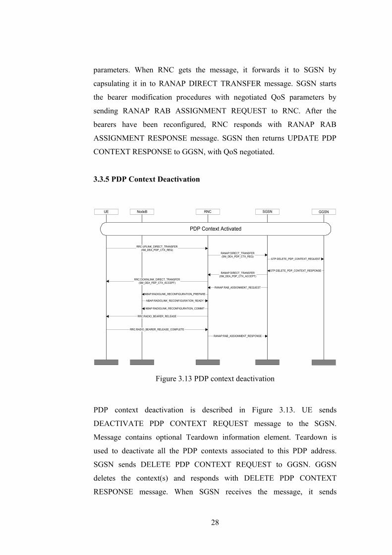
3.3.5 PDP Context Deactivation
SGSNRNCNodeBUE
RANAP:RAB_ASSIGNMENT_REQUEST
RRC:RADIO_BEARER_RELEASE
RRC:UPLINK_DIRECT_TRANSFER(SM_DEA_PDP_CTX_REQ)
RANAP:DIRECT_TRANSFER(SM_DEA_PDP_CTX_REQ)
NBAP:RADIOLINK_RECONFIGURATION_PREPARE
NBAP:RADIOLINK_RECONFIGURATION_READY
NBAP:RADIOLINK_RECONFIGURATION_COMMIT
RRC:RADIO_BEARER_RELEASE_COMPLETE
RANAP:RAB_ASSIGNMENT_RESPONSE
GGSN
GTP:DELETE_PDP_CONTEXT_REQUEST
GTP:DELETE_PDP_CONTEXT_RESPONSERANAP:DIRECT_TRANSFER
(SM_DEA_PDP_CTX_ACCEPT)RRC:DOWNLINK_DIRECT_TRANSFER
(SM_DEA_PDP_CTX_ACCEPT)
PDP Context Activated
Figure 3.13 PDP context deactivation
PDP context deactivation is described in Figure 3.13. UE sends
DEACTIVATE PDP CONTEXT REQUEST message to the SGSN.
Message contains optional Teardown information element. Teardown is
used to deactivate all the PDP contexts associated to this PDP address.
SGSN sends DELETE PDP CONTEXT REQUEST to GGSN. GGSN
deletes the context(s) and responds with DELETE PDP CONTEXT
RESPONSE message. When SGSN receives the message, it sends
28
DEACTIVATE PDP CONTEXT RESPONSE to UE. It also starts bearer
release procedure by sending RANAP RAB ASSIGNMENT REQUEST to
the RNC. RNC releases bearers and replies with RANAP RAB
ASSIGNMENT RESPONSE message.
29

4. UMTS PILOT SYSTEM
This chapter describes the implementation part of the thesis. First, some
general information of the project is given in chapter 4.1. Then, the system
architecture and the protocol architecture is depicted, in chapters 4.2 and 4.3
respectively. After that in chapter 4.4 there is a brief look on different tools
and languages used in system development. Then the principles of the
system integration are described in chapter 4.5. Chapter 4.6 describes the
implementation of the PDCP. Interface to WCDMA radio parts is depicted
is chapter 4.7. QoS issues of the system are described in chapter 4.8.
Chapter 4.9 describes the usage of the system. Chapter 4.10 depicts the
validation of the protocols.
4.1 General
The UMTS Pilot system has been developed in Nokia Research Center,
Helsinki. The work started in November 1999 and is still ongoing. The
purpose of the project was to build a platform for demonstrating 3GPP
WCDMA radio and the behaviour and functionality of the latest 3GPP
protocols. The aim was also to develop platform for testing behaviour of
different IP based applications. The system includes UE, UTRAN and Core
Network emulators. The protocols can be connected to real 3GPP WCDMA
radio, or alternatively radio interface can be replaced with UDP socket. The
radio interface was also developed in NRC Helsinki. The system can also be
connected to Nokia's 3G SGSN product.
The Pilot system has been delivered to several teleoperators around the
world. It has also been demonstrated in several conferencies and exhibitions,
such as Cebit in Germany 2001.
The system enables setting up multiple PDP contexts: primary and
secondary, for IPv4 and IPv6 based applications. It is possible to connect all
30
kinds of IP based applications, also commercial, to the system. In
demonstrations, for example, streaming, video conferencing and web
browsing were shown.
Because the system was designed mainly for demonstration purposes there
are some limitations compared to the commercial systems, for example,
there is only one NodeB and no Iur interface. Also only one UE can be
connected to the system at the time. Iub interface is "reduced" version, only
NBAP protocol is present, lower layers are replaced by socket. Maximum
data rate of the air interface (Uu) is limited to 384 kbits/s.
Protocols are implemented using both SDL (Specification and Description
Language) and CVOPS (C-based Virtual Operating System). In chapter 4.3
this is shown in more detailed way. Almost all the protocol skeletons have
been received from other NRC projects. Skeleton means that the protocols
were not complete implementations, for example messages and primitives
were not fully filled resulting that some required information elements and
parameters were missing. Filling the messages (and primitives) with correct
parameters took a quite a long time. PDCP and RRM (not exactly protocol)
were output of this project. Also interface to WCDMA radio parts (layer 1)
was implemented in the project. Thus, the main focus has been in
integrating the protocols working together. Because the protocols were
implemented in different projects using different tools, integration process
became more complicated. A special tool had been developed in NRC for
integrating SDL and CVOPS parts together; tool is called SDT and CVOPS
Integration Utility (SCIU). Actually, rather than a tool it consists of
modified kernels of CVOPS and SDT (SDL Tool). SCIU is discussed in
more detailed way in chapter 4.4.4. The testing of the system took a large
amount of time although SDT offers good tracing facilities. In the 3GPP
WCDMA radio, messages are exchanged between protocol stack and radio
parts in exact frequency of 10 milliseconds and that accuracy brought very
31
challenging requirements to the real-time protocols. It meant that there was
a need to optimise the performance of the protocol implementations.
The project was divided into three phases and in every phase additional
features were added to the system. This division was done because the
3GPP protocol specification versions evolved continuously and therefore
also protocol implementations needed to be updated. The author was in his
part responsible for system integration and implementation of the PDCP
protocol and also in integrating the system with the WCDMA radio parts.
System integration and implementation of the required features to the
protocols were the most time-consuming tasks. Both of them took several
months in every phase. Testing the system (also with the WCDMA radio
parts) was a continuous task through the project.
4.2 Pilot System Architecture
The Pilot system consists of three PC's with Linux operating system. UE
and UTRAN machines are card PC's with the VME (VERSAmodule
Eurocard) interface. VME interface is used in communication with
baseband. Baseband is a unit that handles layer 1 processing of the data,
channel coding, interleaving, rate matching etc. Radio Frequency (RF)
sends the processed data to the air and receives the data from the air.
Baseband and RF compose the Layer 1.
UTRAN PC has an ATM card for enabling ATM connection towards
SGSN. Application PCs and UE Linux PC are connected to hub. Figure 4.1
presents the architecture with real WCDMA radio parts and RF parts.
32

Application PC 1
Application PC 2
Internet
UE PC
Hub
baseband
UTRAN PC
baseband
VME bus VME bus
SGSN, GGSN, HLR
ATM
RF RF
airinterface
Iu-PS
Figure 4.1 Pilot system with 3G WCDMA radio
It was possible to replace the WCDMA radio and RF with WCDMA radio
emulator process inside UE and UTRAN machines, then the traffic in radio
interface goes via UDP socket, as shown in Figure 4.2. The real WCDMA
radio brought more complexity to the system. The reason for having
WCDMA radio emulator was that then it was possible to test the
functionality of the protocols before connecting them to the real WCDMA
radio.
Application PC 1
Application PC 2
Internet
UE PC
Hub
UTRAN PC
SGSN, GGSN, HLR
ATM
"air interface"
Iu-PS
Figure 4.2 Pilot system without 3G WCDMA radio
33
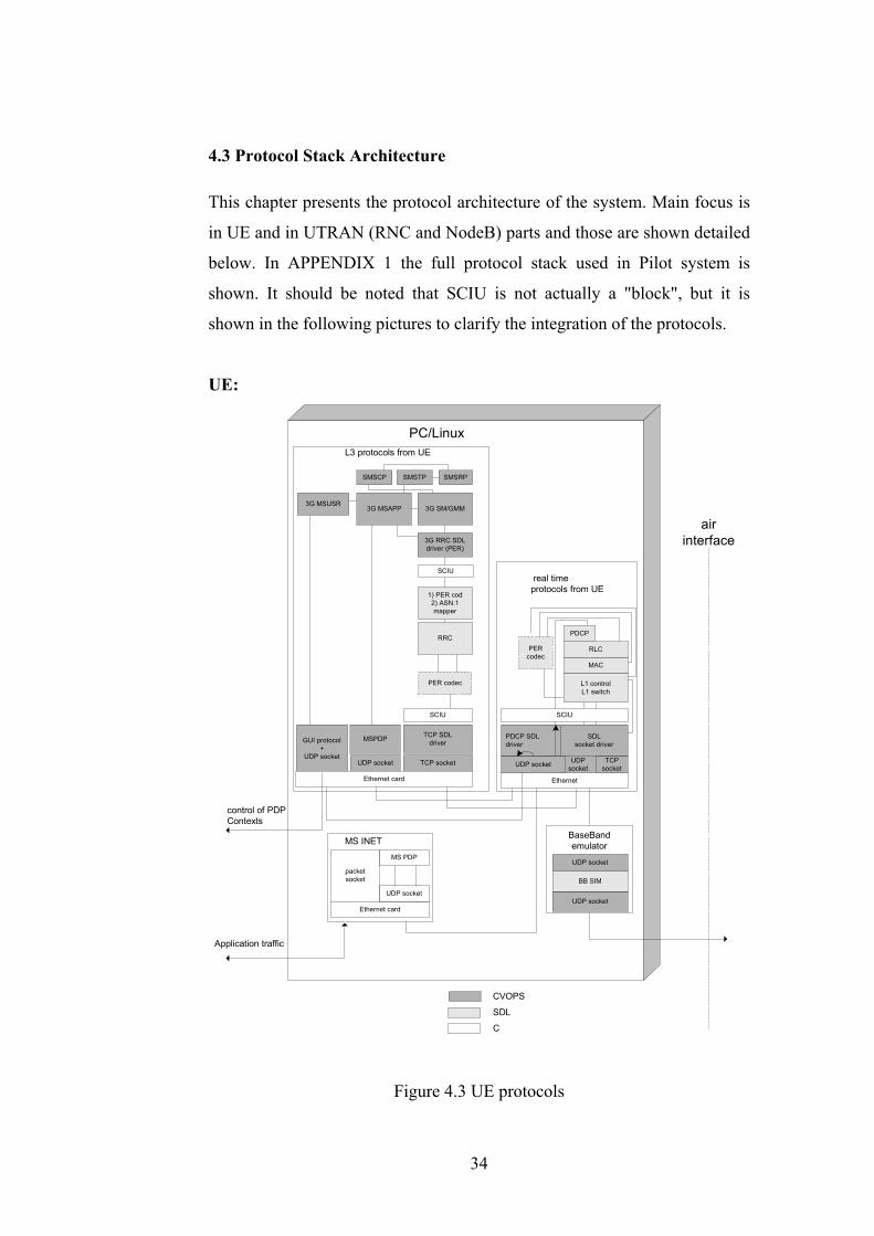
4.3 Protocol Stack Architecture
This chapter presents the protocol architecture of the system. Main focus is
in UE and in UTRAN (RNC and NodeB) parts and those are shown detailed
below. In APPENDIX 1 the full protocol stack used in Pilot system is
shown. It should be noted that SCIU is not actually a "block", but it is
shown in the following pictures to clarify the integration of the protocols.
UE:
L3 protocols from UE
real timeprotocols from UE
MAC
RLC
PDCP
SCIU
PC/Linux
PERcodec
TCP SDLdriver
UDPsocket
Ethernet
TCP socket
1) PER cod2) ASN.1mapper
3G RRC SDLdriver (PER)
MSPDP
SMSRPSMSTPSMSCP
3G SM/GMM
CVOPS
SDL
C
PDCP SDLdriver
UDP socket
RRC
SCIU
L1 controlL1 switch
BaseBandemulator
UDP socket
UDP socket
BB SIM
SDLsocket driver
TCPsocket
3G MSAPP3G MSUSR
UDP socket
GUI protocol+
UDP socket
MS INET
packetsocket
Ethernet card
UDP socket
MS PDP
Application traffic
Ethernet card
airinterface
control of PDPContexts
SCIU
PER codec
Figure 4.3 UE protocols
34
The UE protocol stack has been divided into two processes, L3 (Layer 3)
process and real-time process. All L3 protocols are run in L3 process and all
real-time protocols in real-time process. There are also two additional
processes in the picture, Baseband emulator and MSINET. MSINET is
basically needed for capturing and routing of the IP packets between UE
Linux PC and Application PC. MSINET is discussed more detailed in
chapter 4.9. Baseband emulator is used for replacing the functionality of the
real 3G WCDMA radio when UDP socket is used in the radio interface.
The real-time process contains PDCP, RLC and MAC protocols. There are
also some additional blocks, such as Packet Encoding Rule (PER) codec
(described in chapter 4.5) and L1 control/switch. All above-mentioned
blocks are coded using SDL. There are some blocks handling sockets, those
are coded using CVOPS. Also SCIU drivers are needed, such as
pdcp_sdt_driver and tcp_socket_driver. The general description of the SCIU
drivers is given in chapter 4.4.4. Most of the protocols in L3 process have
been implemented using CVOPS, such as GMM/SM. RRC and PER codec
have been implemented with SDL.
35

UTRAN:
CVOPSSDL
Node B + real timeprotocols from RNC
L3 protocols in RNC
NBAP
MAC forBCH
UDP socketdrv
CLIP overATM
to 3GSGSN
to 3GSGSN
RLC
MAC
GTP-U
SCIU
RANAP SDLdriver
PDCP
GTP-U SDLdrv
PERcodec
SCIU
GTP-UAdapter
TCP SDLdriver
GTPcontrol(PER)
NBAPSDL
driver
Ethernet card
TCP socket
NBAPSDL
driver
SCIU
NBAP
PER codec
TCP socket
Ethernet
L1 controlL1 switch
UDP socket
BaseBandemulatorUDP socket
UDP socket
BB SIM
SDLsocket driver
TCP socket MTP3b-if(TCP socket)
MTP3B server
MTP3b-if(TCP socket)
MTP3B
SSCF
SSCOP
CPCSATM card
(AAL5)
Linux PC
SCCP
RRM
RRC
airinterface
RANAPRRC'
SCIU
Figure 4.4 UTRAN protocols
UTRAN side has been divided into four processes, Baseband emulator,
MTP3B server and NodeB with the real-time protocols from RNC and L3
protocols of the RNC. Functionality of the Baseband emulator is similar to
the UE side. MTP3B server handles the signalling connections needed by
RANAP and SCCP towards 3G SGSN. It is coded using CVOPS.
L3 process contains RANAP, RRM, NBAP and RRC protocols and PER
codec block, those are SDL implementations. There are also SCIU drivers,
for example nbap_sdt_driver and ranap_sdt_driver.
36
NodeB with real-time protocols from RNC contains NBAP, RRC', MAC,
RLC and PDCP protocols and PER codec. Those were implemented with
SDL. SCIU drivers and GTP-U is implemented with CVOPS.
4.4 Development Environment
In this chapter the development environment is described. First SDL and
SDT are described. Then CVOPS and also brief description about SCIU and
ASN.1 (Abstract Syntax Notation One).
4.4.1 SDL
SDL is a standard language for specifying and describing systems [7]. It has
been developed and standardised by ITU-T (International
Telecommunication Union, Telecommunication Sector) in the
recommendation Z.100. SDL has designed especially for telecommunication
industry and it has been found out to be suitable even for product level
implementation [14].
SDL has a graphical representation (SDL/GR, SDL Graphical
Representation) in addition to the textual representation (SDL/PR, SDL
Phrase Representation). The graphical representation has made the language
user-friendly and easy to use [7].
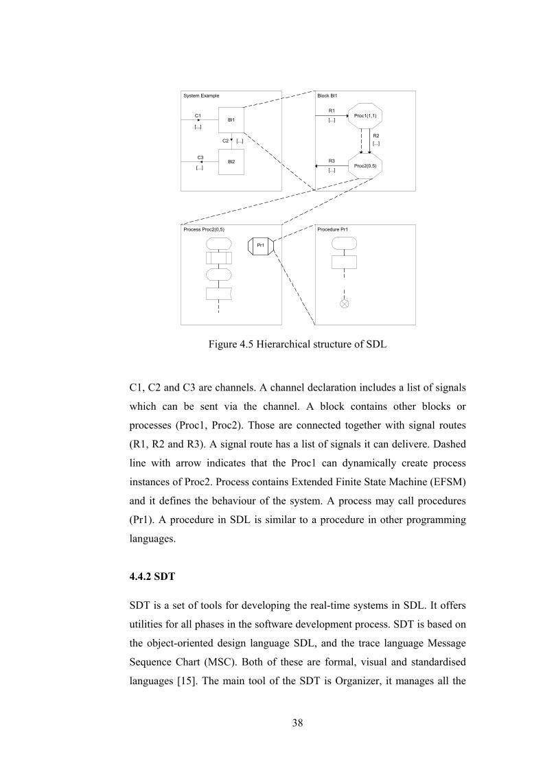
The SDL describes system structure in a hierarchical manner, see Figure 4.5
[15]. The highest level is a system level. The system level is composed of
one or several blocks (Bl1 and Bl2) connected by channels together or to
environment.
37
System Example Block Bl1
Process Proc2(0,5) Procedure Pr1
Bl1
Bl2
[...]
[...]
[...]
C1
C2
C3
Proc1(1,1)
Proc2(0,5)
R1
R2
R3
[...]
[...]
[...]
Pr1
Figure 4.5 Hierarchical structure of SDL
C1, C2 and C3 are channels. A channel declaration includes a list of signals
which can be sent via the channel. A block contains other blocks or
processes (Proc1, Proc2). Those are connected together with signal routes
(R1, R2 and R3). A signal route has a list of signals it can delivere. Dashed
line with arrow indicates that the Proc1 can dynamically create process
instances of Proc2. Process contains Extended Finite State Machine (EFSM)
and it defines the behaviour of the system. A process may call procedures
(Pr1). A procedure in SDL is similar to a procedure in other programming
languages.
4.4.2 SDT
SDT is a set of tools for developing the real-time systems in SDL. It offers
utilities for all phases in the software development process. SDT is based on
the object-oriented design language SDL, and the trace language Message
Sequence Chart (MSC). Both of these are formal, visual and standardised
languages [15]. The main tool of the SDT is Organizer, it manages all the
38
SDL designs. Other tools are SDL editor, analysator, code generator and
simulator. SDL editor offers a graphical user interface for handling of SDL
diagrams. It also does real-time syntax checking for SDL designs.
Analysation is carried out before the code generation, it checks syntactics
and semantics of the design. The analyser also converts Graphical
Representation to Phrase Representation. The code generator compiles the
SDL representation to C code. There are several code generators for
different purposes, for example Cbasic, Cadvanced and Cmicro. Cmicro is
designed to be used in embedded systems. The generated code is much more
compact than using the other code generators. Cbasic is mainly designed for
simulation purposes and Cadvanced for building any kind of application.
With help of the simulator it is possible to check how the system behaves
when running it. It is useful for detecting run-time errors in the design.
Using simulators MSC trace it is possible to see the signalling in a graphical
format.
SDT enables the designer to embed external code to the system. That code
could be written in C or C++. For example, PDU encoding and decoding
functions are usually implemented by using (tool generated) C functions.
The code SDT produces can be compiled to various platforms, such as
Linux, Windows and VxWorks (a real-time operating system).
4.4.3 CVOPS
CVOPS is a tool and run-time environment for implementing
communication protocols. It has been developed by the Technical Research
Centre of Finland (VTT) [11]. It has been used for long time in the
telecommunication industry.
CVOPS offers mechanisms for protocol development, such as scheduling,
message passing, timers and memory handling. It also includes a special
39

language for implementing protocol logic, Extended Finite State Automaton
(EFSA).
A CVOPS system may consists of several protocols, which may all include
multiple instances (connections). One instance from a protocol implemented
with CVOPS is called virtual task (vtask). Protocol stack is implemented by
connecting these vtasks together. CVOPS handles communication between
vtasks. A vtask sends messages to other vtasks via its interfaces. Both sides
of an interface have their own parameter functions, putParameters and
getParameters. PutParameter is called by CVOPS when the message is sent
from a vtask and getParameter is called when the message is received by a
vtask. This is described in Figure 4.6 [11].
putParameters getParametersVTASK in layer (N+1)
putParametersgetParametersVTASK in layer (N)
message message
Figure 4.6 Parameter functions of CVOPS
The communication between CVOPS and environment goes through so
called driver vtasks [10]. Driver vtask converts a message to the form it can
be sent to the environment. Also when a message is received from the
environment driver vtask creates CVOPS message and sends it to other
vtasks [10].
40
4.4.4 SCIU
In NRC there are a lot of CVOPS and SDL protocol implementations
(protocol libraries). It is beneficial to be able to use CVOPS and SDL
protocols in a same system. The purpose of SCIU is to make CVOPS and
SDL operate together.
The SCIU integrates CVOPS and SDT kernels so that they both have own
message schedulers. CVOPS scheduler works as a main scheduler of the
system. If it notices that there is a message in the SDT message queue, it
calls SDT scheduler to handle that message. After the SDT scheduler has
handled the message the control returns to the CVOPS scheduler.
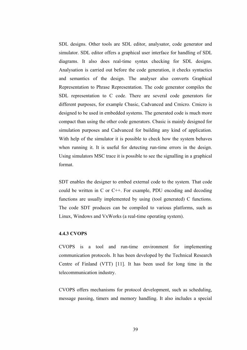
SCIU driver is CVOPS vtask that is used to encode, decode, send and
receive messages between SDT and other CVOPS vtasks. Because data
types and messages are different in the SDT and CVOPS, the message
parameters need to be converted to the data types used by the receiver of the
message. Figure 4.7 shows how messages pass the driver [17].
SCIUDRIVER
SDT protocol
CVOPS protocol
getParameters
runSdtDriver()
1. decode CVOPSparameters
2. encode SDTparameters
putParameters
sdtdriverHandleEvent()
1. decode SDT parameters
2. encode CVOPSparameters
Figure 4.7 Message passing through SCIU driver
41

4.4.5 ASN.1
ASN.1 is a notation for defining data types and structures. It is widely used
in communication industry, for example, 3GPP layer 3 protocol
specifications use ASN.1 for defining messages. ASN.1 defines the abstract
syntax of the data but it does not affect how the data is encoded. The basic
principle is to define a small number of different data types by defining their
possible values and give rules to combine these into increasingly
complicated types. Packet Encoding Rule (PER) is one of the encoding rules
that provides a transfer syntax for the ASN.1 types. ASN.1 and PER
together specifies a machine-independent bit-pattern representation during
transfer for ASN.1 types.
4.5 System Integration Principles
Most of the protocols were received from the other projects, so the main
task was to integrate them. Because the protocols were coded using different
tools and languages, the job was more difficult compared to the situation if
they had all been coded with the same language. Also the primitive
interfaces were defined differently, so there was a need to modify them. As
depicted earlier in chapter 4.1, the protocols were not complete
implementations, for example, some required parameters and information
elements were missing. Therefore, it took a quite long time to implement
those.
SCIU was needed to get SDL and CVOPS protocol implementations
working together. Where CVOPS protocol was facing SDL protocol there
was a need to implement a special vtask between them, called SCIU driver.
The main task of the SCIU driver is to map the SDT primitives and their
parameters corresponding CVOPS primitives and vice versa.
The UE stack has been divided so that the real-time protocols are in
different process than the L3 protocols. The same is true on the RNC side.
42

The division was done because real-time protocols needed to achieve the
requirements set by L1 and protocols itselves. Another issue was tracing,
usually it was enough to see L3 level tracing and setting that on did not
exhaust the real-time protocols.
The primitive interface between RRC and lower layers (PDCP, RLC, MAC
and L1 control/switch) is complicated and because the primitives are
defined using ASN.1, the parameter mapping in SCIU driver would have
been troublesome without PER codec. In addition, because the ASN.1 tools
generate C data structures from the ASN.1 definitions, the smallest change
in the ASN.1 definition would have caused major modifications in SCIU
driver. PER codec is a SDL block that uses encoding and decoding
functions generated by the ASN.1 tools. PER coding of the structure before
sending it to SCIU driver makes the mapping easier and there is a need to
map only one parameter. On the receiver side, peer PER codec needs only
decode the PER encoded parameter, after that the primitive can be passed to
the receiver.
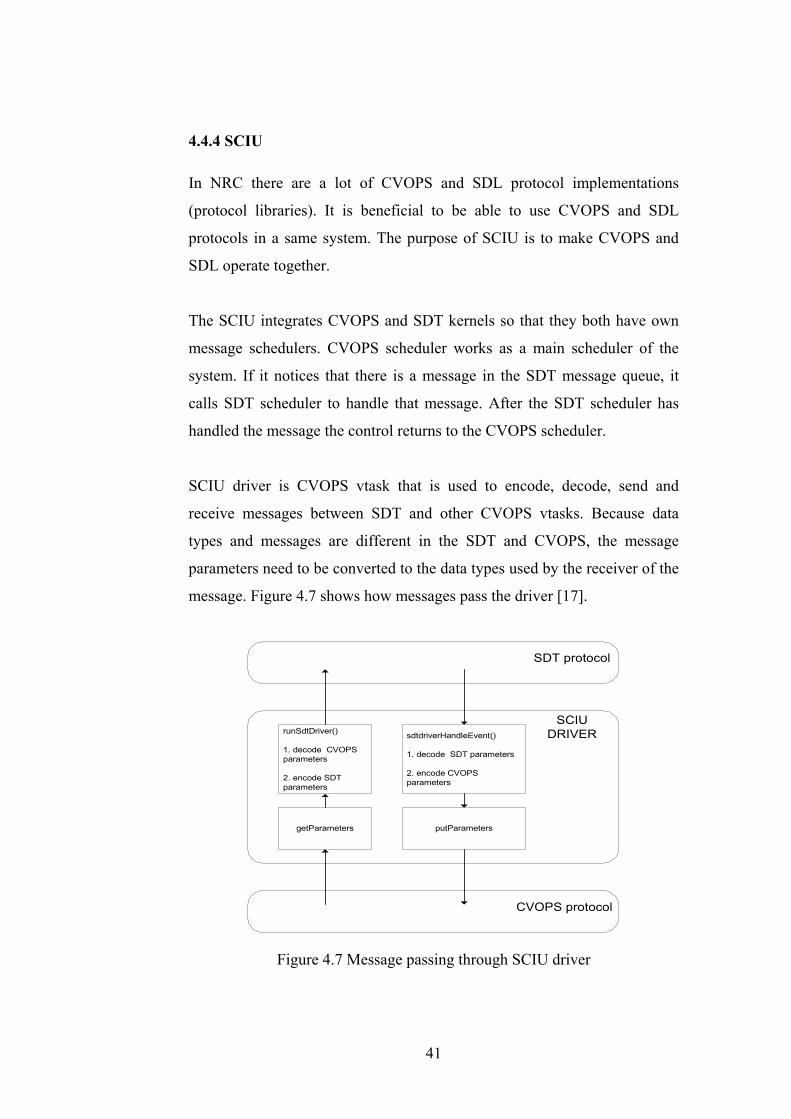
Figure 4.8 illustrates how the pdcp_ue_config_req –primitive is handled.
When RRC sends primitive to PDCP, it goes first to PER codec. The PER
codec encodes the message to transfer syntax and sends it to socket (actually
there is SCIU driver between PER codec and TCP socket). On the receiver
side, a message comes to PER codec and it is decoded to local syntax and
the message is then passed on to PDCP.
43
RRC
PER codec
TCP SOCKET
PDCP
PER codec
TCP SOCKET
UE_L3 UE_RT
pdcp_ue_config_req(rb_id, hc_algorithm, ...)
pdcp_ue_config_req(rb_id, hc_algorithm, ...)
cnf_msg(PER coded string)
cnf_msg(PER coded string)
Figure 4.8 Primitive encoding and decoding
In the Pilot system the software development was done in Sun Solaris
machines. A version control system was used there. The target environment,
were the system was executed, was PC's with Linux operating system. The
system was first tested in Solaris with real-time memory debugging tools
(Purify) and other software development tools and after the system worked
correctly in Solaris, it was transferred to Linux. It was not possible to test
everything in Solaris because actual real-time testing with real application
and WCDMA radio had to be done in Linux. One defienciency in software
development was that the good memory debugging tools were not available
in the target environment. Therefore the Gnu Debugger (GDB) was proved
to be very valuable in Linux. Because in Solaris there were no ATM card,
the system had to be changed slightly before it was possible to test in
Solaris. ATM was then replaced with TCP socket.
The tracing of the system execution is essential and luckily SDT provides
quite sophisticated tracing facilities for analysing the behaviour of the
system. It is possible to set the tracing level depending on what kind of
44
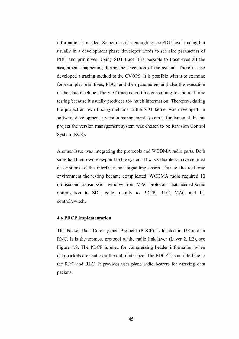
information is needed. Sometimes it is enough to see PDU level tracing but
usually in a development phase developer needs to see also parameters of
PDU and primitives. Using SDT trace it is possible to trace even all the
assignments happening during the execution of the system. There is also
developed a tracing method to the CVOPS. It is possible with it to examine
for example, primitives, PDUs and their parameters and also the execution
of the state machine. The SDT trace is too time consuming for the real-time
testing because it usually produces too much information. Therefore, during
the project an own tracing methods to the SDT kernel was developed. In
software development a version management system is fundamental. In this
project the version management system was chosen to be Revision Control
System (RCS).
Another issue was integrating the protocols and WCDMA radio parts. Both
sides had their own viewpoint to the system. It was valuable to have detailed
descriptions of the interfaces and signalling charts. Due to the real-time
environment the testing became complicated. WCDMA radio required 10
millisecond transmission window from MAC protocol. That needed some
optimisation to SDL code, mainly to PDCP, RLC, MAC and L1
control/switch.
4.6 PDCP Implementation
The Packet Data Convergence Protocol (PDCP) is located in UE and in
RNC. It is the topmost protocol of the radio link layer (Layer 2, L2), see
Figure 4.9. The PDCP is used for compressing header information when
data packets are sent over the radio interface. The PDCP has an interface to
the RRC and RLC. It provides user plane radio bearers for carrying data
packets.
45
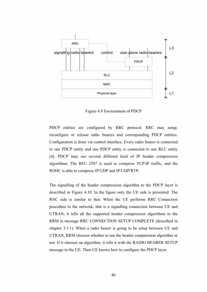
PDCP
RLC
MAC
Physical layer
RRC
user plane radio bearerssignalling radio bearers control
L2
L3
L1
Figure 4.9 Environment of PDCP
PDCP entities are configured by RRC protocol. RRC may setup,
reconfigure or release radio bearers and corresponding PDCP entities.
Configuration is done via control interface. Every radio bearer is connected
to one PDCP entity and one PDCP entity is connected to one RLC entity
[4]. PDCP may use several different kind of IP header compression
algorithms. The RFC 2507 is used to compress TCP/IP traffic, and the
ROHC is able to compress IP/UDP and IP/UDP/RTP.
The signalling of the header compression algorithm to the PDCP layer is
described in Figure 4.10. In the figure only the UE side is presented. The
RNC side is similar to that. When the UE performs RRC Connection
procedure to the network, that is a signalling connection between UE and
UTRAN, it tells all the supported header compression algorithms to the
RRM in message RRC CONNECTION SETUP COMPLETE (described in
chapter 3.3.1). When a radio bearer is going to be setup between UE and
UTRAN, RRM chooses whether to use the header compression algorithm or
not. If it chooses an algorithm, it tells it with the RADIO BEARER SETUP
message to the UE. Then UE knows how to configure the PDCP layer.
46

RNC_RRCUE_RRC
RRC:RADIO_BEARER_SETUP(algorithm, rb_id, ...)
RRC:RADIO_BEARER_SETUP_COMPLETE
UE_PDCP
pdcp_ue_config_req(algorithm, rb_id, ...)
Setup PDCPconnection
RRC:RRC_CONNECTION_SETUP_COMPLETE(supported algorithms, ...)
Setting up PDP Context
pdcp_ue_config_cnf(rb_id, ...)
Figure 4.10 PDCP connection setup
SDL implementation of the PDCP contains two processes. One entity is
called RED (Routing Encoding/Decoding), and the other one CONN
(connection), see Figure 4.11. The RED is a static process, created when the
system is started. It handles routing of the data packets and control
signalling to the correct connections, to CONN process. Usually (in NRC's
SDL protocol development) also encoding and decoding of the Protocol
Data Unit (PDU) is done in the RED process [14]. But in case of PDCP
there was a need to make it faster by reducing the number of the signals, and
therefore encoding and decoding happens in the CONN process. RED
handles creation of the dynamic CONN processes.
47
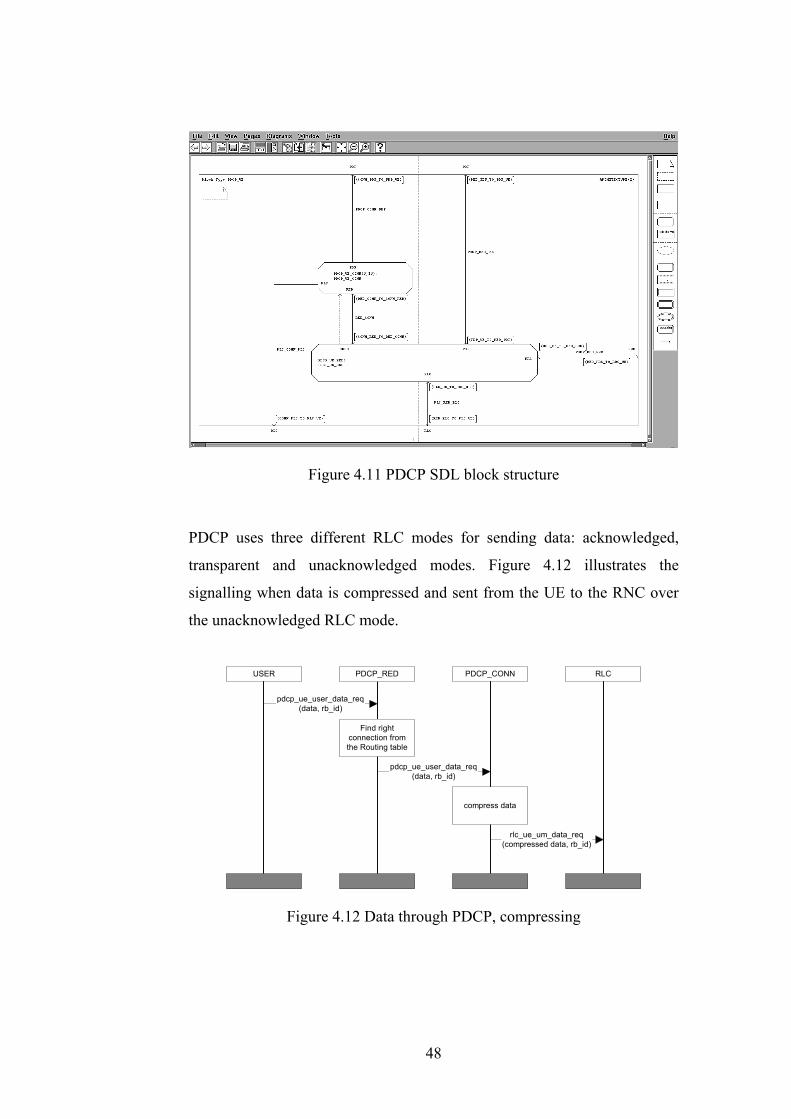
Figure 4.11 PDCP SDL block structure
PDCP uses three different RLC modes for sending data: acknowledged,
transparent and unacknowledged modes. Figure 4.12 illustrates the
signalling when data is compressed and sent from the UE to the RNC over
the unacknowledged RLC mode.
PDCP_CONNUSER
pdcp_ue_user_data_req(data, rb_id)
PDCP_RED
Find rightconnection fromthe Routing table
pdcp_ue_user_data_req(data, rb_id)
compress data
RLC
rlc_ue_um_data_req(compressed data, rb_id)
Figure 4.12 Data through PDCP, compressing
48

On the receiving side, Figure 4.13, signalling sequence is the opposite. Data
is IP packet produced by the application, compressed data is compressed IP
packet (for example compressed IP/UDP/RTP headers and uncompressed
payload), rb_id identifies the radio bearer and rnti (Radio Network
Temporary Identity) identifies the UE.
PDCP_RED USER
pdcp_rnc_user_data_ind(data, rb_id, rnti)
PDCP_CONN
decompress data
pdcp_rnc_user_data_ind(compressed data, rb_id,
rnti)
Find rightconnection fromthe Routing table
RLC
rlc_rnc_um_data_ind(compressed data, rb_id,
rnti)
Figure 4.13 Data through PDCP, decompressing
Header compression
The Voice over IP call is usually IP/UDP/RTP based traffic. The packet
then has IP header (20 bytes for IPv4, 40 bytes for IPv6), UDP header (12
bytes) and RTP header (8 bytes). Payload of the packet depends largely on
the speech coding. It can be as low as 15-20 bytes [13]. In this case, most of
the data transferred over air interface is header information.
Header compression of IP flow is possible due to the fact that the fields in
the headers of IP packets are either constant or changing in a known pattern
between consecutive packets in the same flow. It is possible to send only
information regarding the nature of the changing fields of the headers with
respect to the reference packet in the same IP flow. [6] Constant information
in the headers, such as UDP port numbers and IP addresses, needs only to
49
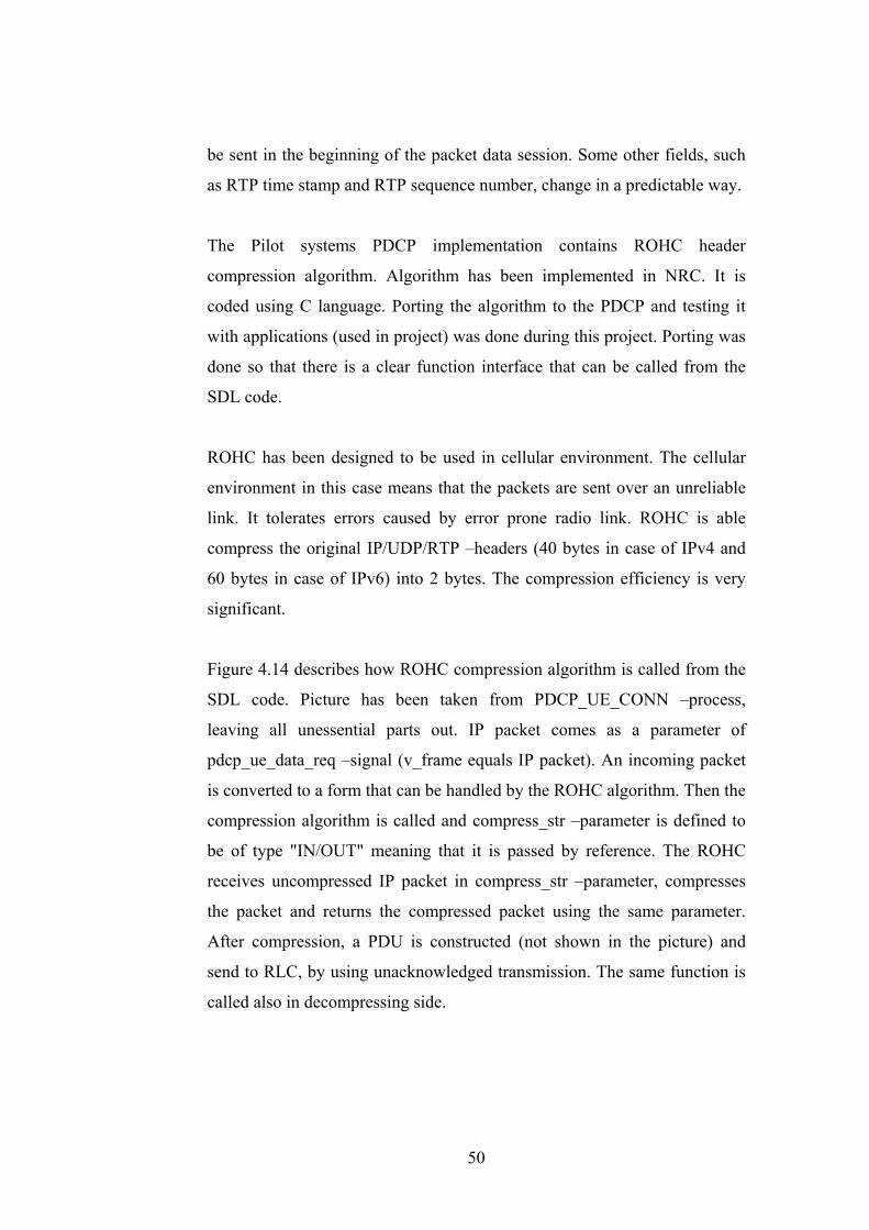
be sent in the beginning of the packet data session. Some other fields, such
as RTP time stamp and RTP sequence number, change in a predictable way.
The Pilot systems PDCP implementation contains ROHC header
compression algorithm. Algorithm has been implemented in NRC. It is
coded using C language. Porting the algorithm to the PDCP and testing it
with applications (used in project) was done during this project. Porting was
done so that there is a clear function interface that can be called from the
SDL code.
ROHC has been designed to be used in cellular environment. The cellular
environment in this case means that the packets are sent over an unreliable
link. It tolerates errors caused by error prone radio link. ROHC is able
compress the original IP/UDP/RTP –headers (40 bytes in case of IPv4 and
60 bytes in case of IPv6) into 2 bytes. The compression efficiency is very
significant.
Figure 4.14 describes how ROHC compression algorithm is called from the
SDL code. Picture has been taken from PDCP_UE_CONN –process,
leaving all unessential parts out. IP packet comes as a parameter of
pdcp_ue_data_req –signal (v_frame equals IP packet). An incoming packet
is converted to a form that can be handled by the ROHC algorithm. Then the
compression algorithm is called and compress_str –parameter is defined to
be of type "IN/OUT" meaning that it is passed by reference. The ROHC
receives uncompressed IP packet in compress_str –parameter, compresses
the packet and returns the compressed packet using the same parameter.
After compression, a PDU is constructed (not shown in the picture) and
send to RLC, by using unacknowledged transmission. The same function is
called also in decompressing side.
50
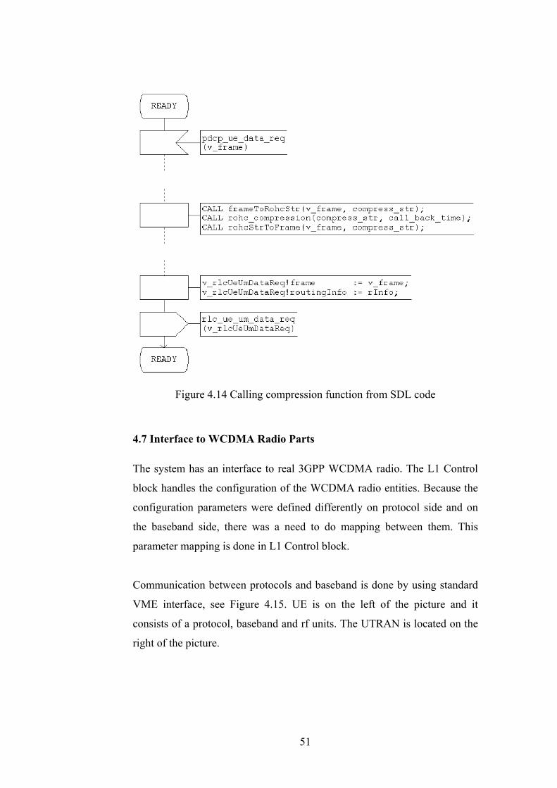
Figure 4.14 Calling compression function from SDL code
4.7 Interface to WCDMA Radio Parts
The system has an interface to real 3GPP WCDMA radio. The L1 Control
block handles the configuration of the WCDMA radio entities. Because the
configuration parameters were defined differently on protocol side and on
the baseband side, there was a need to do mapping between them. This
parameter mapping is done in L1 Control block.
Communication between protocols and baseband is done by using standard
VME interface, see Figure 4.15. UE is on the left of the picture and it
consists of a protocol, baseband and rf units. The UTRAN is located on the
right of the picture.
51
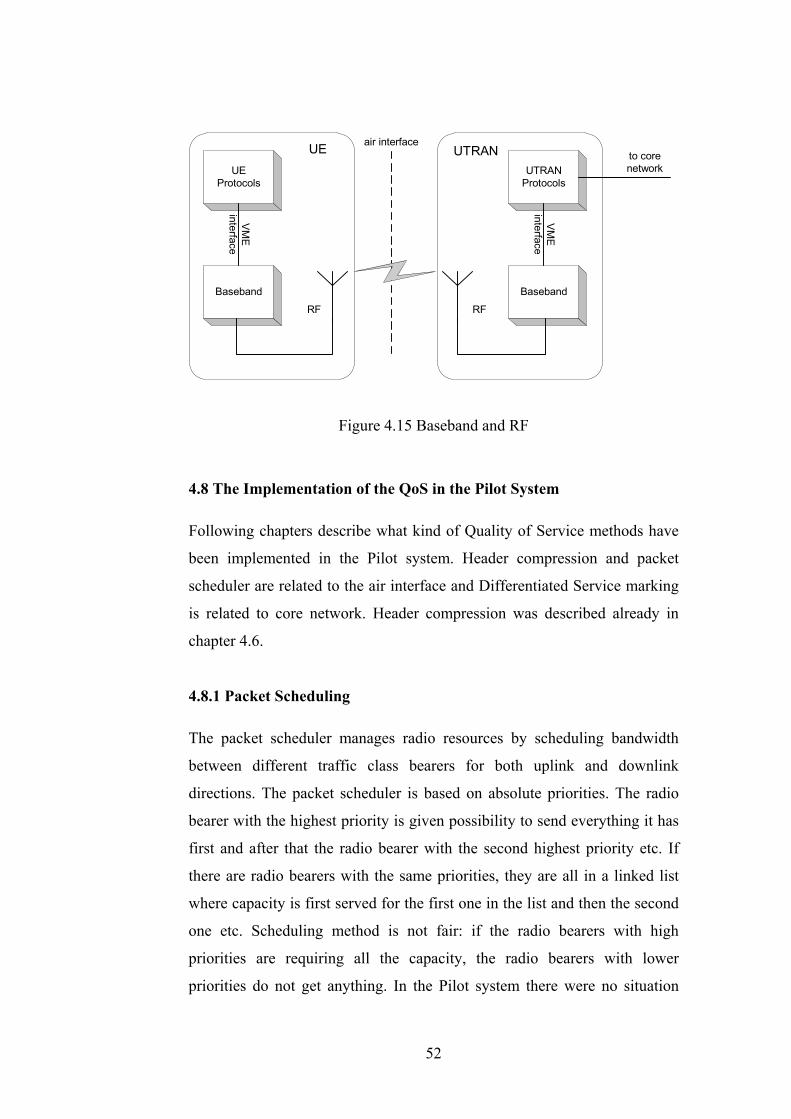
UTRAN
RF RF
UEProtocols
Baseband
VME
interface
UTRANProtocols
Baseband
VME
interface
air interfaceUE to corenetwork
Figure 4.15 Baseband and RF
4.8 The Implementation of the QoS in the Pilot System
Following chapters describe what kind of Quality of Service methods have
been implemented in the Pilot system. Header compression and packet
scheduler are related to the air interface and Differentiated Service marking
is related to core network. Header compression was described already in
chapter 4.6.
4.8.1 Packet Scheduling
The packet scheduler manages radio resources by scheduling bandwidth
between different traffic class bearers for both uplink and downlink
directions. The packet scheduler is based on absolute priorities. The radio
bearer with the highest priority is given possibility to send everything it has
first and after that the radio bearer with the second highest priority etc. If
there are radio bearers with the same priorities, they are all in a linked list
where capacity is first served for the first one in the list and then the second
one etc. Scheduling method is not fair: if the radio bearers with high
priorities are requiring all the capacity, the radio bearers with lower
priorities do not get anything. In the Pilot system there were no situation
52

when two radio bearers had same priority values, so this kind of scheduling
was adequate.
Capacity is based on transport blocks. A transport block equals to MAC
PDU. A transport format is a format L1 offers data to MAC and vice versa.
It consists of one or more transport blocks. MAC always selects the slowest
transport format which can carry all the data RLC protocol has in its buffers.
In the Pilot system the priority value of the bearer is determined in Packet
Scheduler unit of RRM. It is calculated from the values of traffic class and
traffic handling priority, received in RAB ASSIGNMENT REQUEST
message, as depicted in Figure 4.16. RRM calculates also the smallest
transport format set that still fulfills bandwidth requirements informed in
RAB ASSIGNMENT REQUEST message. The calculation is based on
guaranteed bit rate field.
SGSNRNCUE
RANAP:RAB_ASSIGNMENT_REQUEST(traffic class, traffic handling priority, guaranteed
bitrate, ...)
RRC:RADIO_BEARER_SETUP(mac priority, transport formats, ...)
PDP Context Activation started
RRC:RADIO_BEARER_SETUP_COMPLETERANAP:RAB_ASSIGNMENT_RESPONSE
RRM chooses MAC priority valueaccording to traffic class andtraffic handling priority values
andtransport formats by calculating
guaranteed bit rate fields
PDP Context Activation continues
Figure 4.16 Setting the MAC priority and transport formats
53
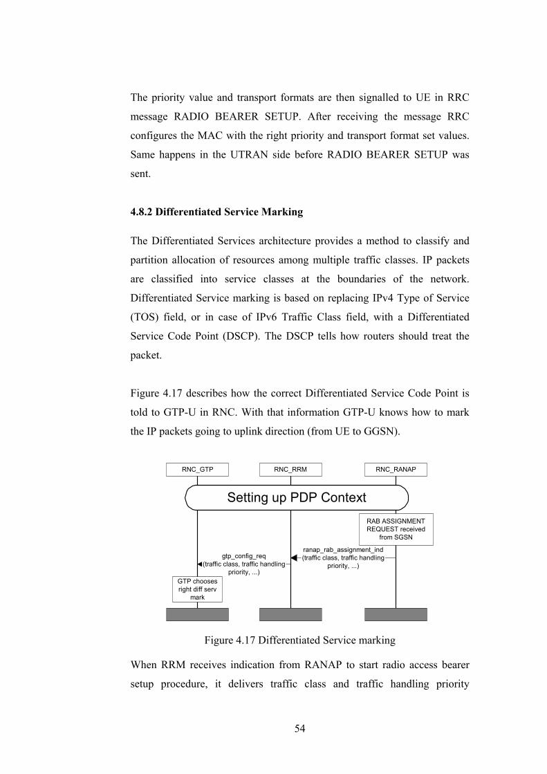
The priority value and transport formats are then signalled to UE in RRC
message RADIO BEARER SETUP. After receiving the message RRC
configures the MAC with the right priority and transport format set values.
Same happens in the UTRAN side before RADIO BEARER SETUP was
sent.
4.8.2 Differentiated Service Marking
The Differentiated Services architecture provides a method to classify and
partition allocation of resources among multiple traffic classes. IP packets
are classified into service classes at the boundaries of the network.
Differentiated Service marking is based on replacing IPv4 Type of Service
(TOS) field, or in case of IPv6 Traffic Class field, with a Differentiated
Service Code Point (DSCP). The DSCP tells how routers should treat the
packet.
Figure 4.17 describes how the correct Differentiated Service Code Point is
told to GTP-U in RNC. With that information GTP-U knows how to mark
the IP packets going to uplink direction (from UE to GGSN).
RNC_RRM
gtp_config_req(traffic class, traffic handling
priority, ...)
RNC_GTP RNC_RANAP
Setting up PDP Context
ranap_rab_assignment_ind(traffic class, traffic handling
priority, ...)
GTP choosesright diff serv
mark
RAB ASSIGNMENTREQUEST received
from SGSN
Figure 4.17 Differentiated Service marking
When RRM receives indication from RANAP to start radio access bearer
setup procedure, it delivers traffic class and traffic handling priority
54

parameters to the GTP-U. Based on that information GTP-U knows how to
mark packets.
4.9 Interaction of the Application and Pilot System
This chapter describes how the application PCs and protocol stacks
communicate together. First it is depicted how PDP contexts (primary and
secondary) are activated and then how the user plane data traverse through
the system.
Primary PDP Context Activation
MSINET is the process used for capturing user plane IP packets from
ethernet to protocol stack. It also emulates DHCP (Dynamic Host
Configuration Protocol) server to the application PC in case of IPv4 and
takes care of stateless autoconfiguration procedure in case of IPv6. It
connects IPv4/IPv6 application PCs to the protocol stack [12]. The primary
PDP context activation procedure for IPv4 is shown in Figure 4.18.
ApplicationPC MSINET
DHCPdiscovery
resp(xx.xx.yy.yy)
PDP context activate
GGSN
IP addr(xx.xx.yy.yy)
UE_L3
Figure 4.18 PDP context activation using DHCP
The PDP context activation procedure starts when the operating system of
application PC sends a DHCP request for asking IP address from DHCP
55

server. MSINET detects it and triggers the primary PDP context activation
procedure with the predefined default QoS parameters. When the procedure
is completed MSINET returns the IP address, allocated by the GGSN, to the
application PC.
In case of IPv6 the situation is more complicated because there is no DHCP
for IPv6 yet. The procedure starts when the MSINET detects the Router
Solicitation message from the IPv6 application PC. This message contains
application PC's link local address. Then MSINET triggers primary PDP
context activation. With the PDP context activation accept message
MSINET gets the Interface Identifier allocated by the GGSN. After that, as
a data packet, MSINET receives IPv6 Router Advertisement containing
network Prefix Information. Now MSINET can combine these addresses
(Interface Identifier and Network Prefix) together and form IPv6 address for
the application PC.
Secondary PDP Context Activation
The QoS and Session Manager is a graphical tool for setting up QoS
parameters for secondary PDP contexts (i.e. applications). Using the tool it
is possible to define own QoS parameters for video call, web browsing and
other type of applications. The QoS and Session Manager conveys session
activation, modification and deactivation requests sent from the application
to the UE emulator which then start PDP context activation, PDP context
modification or PDP context deactivation procedures for given application.
Figure 4.19 shows how the PDP context activation procedure is performed
using 3G Concept Phone and the QoS and Session Manager.
56

3G concept phone
Pilot System(UE, UTRAN, SGSN, GGSN)
3
21
4
QoS and SessionManager 3G protocols
Figure 4.19 Environment of QoS and Session Manager
1. The end user selects the application from the UE. Let us assume that the
application is a video call. The 3G Concept Phone then sends a request
to QoS and Session Manager for reading QoS parameters for video call.
2. QoS and Session Manager requests UE protocol stack to activate
secondary PDP context with the parameters defined beforehand for
given application type in QoS and Session Manager.
3. Protocol stack responds with the secondary PDP context accept (in case
of successful activation) to QoS and Session Manager. The message
contains negotiated QoS parameters.
4. QoS and Session Manager informs 3G Concept Phone that the context
has been setup and the application may start to signal the actual
application (video call).
For the video call the QoS parameters of the secondary PDP context
activation request can be as depicted in Figure 4.20. These parameters were
described in chapter 3.2. There is also defined Traffic Flow Template for the
video call. Filtering in this case is based on the protocol carried as a IP
payload. Value 17 equals to UDP, so all UDP packets are routed to this PDP
context (it also depends on evaluation precedence).
57
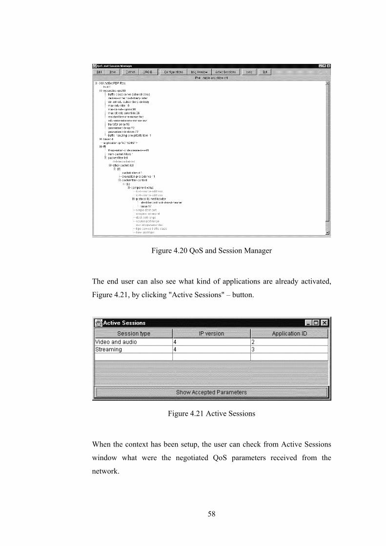
Figure 4.20 QoS and Session Manager
The end user can also see what kind of applications are already activated,
Figure 4.21, by clicking "Active Sessions" – button.
Figure 4.21 Active Sessions
When the context has been setup, the user can check from Active Sessions
window what were the negotiated QoS parameters received from the
network.
58

Data transmission
Because UE may have now multiple active PDP context, primary and one or
more secondary contexts, it is necessary to route IP packets to the correct
PDP context. Routing is based on Traffic Flow Template (see chapter 3.2.3),
which is signalled to GGSN during the activation procedure. TFT contains
filters for routing of the packets, see Figure 4.22.
UE NodeB, RNC, 3G SGSN
Primary PDP context
Secondary PDP context 1
Secondary PDP context 2TFT
3G GGSN
DOWNLINK IPPACKETS
Figure 4.22 TFT filtering
Figure 4.23 shows the flow of the user plane traffic through the system from
the application PC connected to the UE to the SGSN. Packets returning
from the SGSN travel the same route.
TE
eth eth eth ATM
MSINET
RT stack
L3 stack
BB sim BB sim RT stack
L3 stack
Iu-PS to SGSN
UE UTRANUu
Figure 4.23 Packet flow
TE is a application PC and RT stack runs the real-time protocols, i.e. PDCP,
RLC and MAC. In addition to that in the UTRAN side the GTP-U is also
run in RT stack. BB simulator is used to replace the functionality of the real
3GPP WCDMA radio. Uu is the air interface.
59
4.10 Testing and Validation of the Protocol Implementations
The protocol implementations in the Pilot system have been done according
to the 3GPP specifications. Same protocol implementations are used in
several testers for testing Nokia's 3G products and product testing phases
have proved 3GPP compliance.
The MTP3b server and the RObust Header Compression algorithm have
been in a bake-off sessions where they have been tested against the
implementations of other manufacturers.
60
5. CONCLUSION
As the second generation mobile telecommunication systems are mainly
designed for speech, the third generation systems are designed taking into
account technology needs for mobile multimedia telecommunication. The
portion of data is going to bypass speech in the near future. Because the data
is usually carried over packet switched connections, there is a need for
classification the traffic into different traffic classes in order to ensure
promised quality requirements.
In this thesis the focus was in implementation of the Third Generation Pilot
system. From the QoS point of view some important methods were
described, especially those interacting with radio interface. With the help of
the Pilot system, is was possible to see in practise how different methods
affected to the behaviour of the whole system.
The described QoS methods were, packet scheduling, ROHC header
compression and Differentiated Service marking. MAC scheduling was
proved to be practical, by prioritising different traffic class bearers/logical
channels. ROHC reduced significantly the reduntant information sent over
the air interface. The functionality of the Differentiated Service marking
was not yet ensured because no routers supporting marking was available.
The SDL implementation of the PDCP was described. It was found that
SDT is a very useful tool for designing and implementating
telecommunication protocols. Especially it is valuable for rapid prototyping
and piloting. The behaviour of the system and protocols is easy to observe
with help of SDT tracing facility. Integrating SDT and CVOPS protocols
was straightforward with help of the SCIU.
61
It was also found out that Linux operating system is capable enough for
running real-time protocol implementations. That was proved by connecting
protocols to the real 3G WCDMA radio interface.
The Pilot system was demonstrated in several conferencies during 2000 and
2001, such as Cebit, Cannes and UMTS conference in Barcelona. The
system is also installed to Nokia's 3G truck and it tours around the Europe
demonstrating the system to teleoperators. The system is also used as a
testing platform of the 3G applications.
This project gave valuable knowledge to author both in understanding how
UMTS operates and also how to develop and implement Pilot systems. In
the near future the Pilot system is going to be connected to the Nokia's 3G
SGSN product. The results of this project will be used as a basis of new
WCDMA based pilot systems.
62

REFERENCES
[1] 3GPP Technical Specification 23.060 version 4.1.0: General
Packet Radio Service (GPRS): Service Description; Stage 2,
3GPP, 2001.
[2] 3GPP Technical Specification 23.107 version 5.1.0: QoS
Concept and Architecture, 3GPP, 2001.
[3] 3GPP Technical Specification 24.008 version 4.2.1: Mobile
Radio Interface Layer 3 Specification (CC/MM), 3GPP,
2001.
[4] 3GPP Technical Specification 25.323 version 4.1.0:
Description of Packet Data Convergence Protocol (PDCP),
3GPP, 2001.
[5] 3GPP Technical Specification 25.401 version 5.00: UTRAN
Overall Description, 3GPP, 2001.
[6] 3GPP Technical Specification 25.844 version 1.00: Radio
Access Bearer Support Enhancements, 3GPP, 2000.
[7] Ellsberger Jan, Hogrefe Dieter, Sarma Amardeo: SDL:
Formal Object-oriented Language for Communicating
Systems, Pearson Education Limited, 1997. ISBN 0-13-
632886-5.
[8] Holma Harri, Toskala Antti: WCDMA for UMTS: Radio
Access for Third Generation Mobile Communications, John
Wiley & Sons, Ltd, 2001. ISBN 0-471-48687-6.
[9] Kaaranen Heikki, Ahtiainen Ari, Laitinen Lauri, Naghian
Siamäk, Niemi Valtteri: UMTS networks: Architecture,
Mobility and Services, John Wiley & Sons, Ltd, 2001. ISBN
0471 48654 X.
[10] Malka Juhani, Ojanperä Esko: Advanced User's Guide for
CVOPS 6.4. Teleclass, Helsinki, January 2000.
[11] Malka Juhani, Ojanperä Esko: User's Guide for CVOPS 6.4.
Teleclass, Helsinki, January 2000.
63
[12] Mustajärvi Jari, Laine Petri: GPRS/3G Emulator – IPv6
Implementation, NRC internal document.
[13] RFC 3095, "RObust Header Compression (ROHC):
Framework and four profiles: RTP, UDP, ESP, and
uncompressed", July 2001.
[14] Sipilä Juha, Luukkala Vesa: An SDL Implementation
Framework for Third Generation Mobile Communications
System. 10th International SDL Forum, Copenhagen,
Denmark, June 2001. ISBN 3-540-42281-1.
[15] Telelogic Tau 4.2 On-line Help. (2001). Telelogic AB,
Malmö, Sweden.
[16] UMTS Forum. The Path towards UMTS – Technologies for
The Information Society, Report no. 2 from the UMTS
Forum, 1998.
[17] Väre Janne: Implementation Report, SCIU, NRC internal
document, NRC MNW 1999.
64

APPENDIX 1: Protocol stacks
UE
and
UTR
AN e
mul
ator
s Inte
rnal
pro
toco
ls
3GPP
Pro
toco
ls
3GPP Iu-packet interface
Nod
e B
+ re
al ti
me
prot
ocol
s fro
m R
NC
L3 p
roto
cols
from
RN
C
RR
MR
LC
MAC
Ethe
rnet
car
d
Nod
eB +
use
r pla
ne p
roto
cols
from
RN
C
Base
Ban
d C
ontro
l
MAC
for
BCH
RR
C
NBA
P
TCP
sock
et
RR
C
NBA
P
TCP
sock
et
Inte
l P3/
Linu
x
UD
Pso
cket
CLI
P ov
erAT
M
Ethe
rnet
GTP
-U
Ethe
rnet
PDC
P
L3 p
roto
cols
user
pla
nepr
otoc
ols
from
UE
Ethe
rnet
PDC
P RLC
RR
C
TCP
sock
et
MAC
Base
Ban
d C
ontro
l
Inte
l P3/
Linu
x
UD
Pso
cket
UD
Pso
cket
3G S
GSN
pro
duct
Pack
etSo
cket
UD
Pso
cket
MSI
NET
(IP
rout
er)
Base
Band
emul
ator
UD
P so
cket
UD
P so
cket
BB S
IM
Base
Band
emul
ator
UD
P so
cket
UD
P so
cket
BB S
IM
TCP
sock
etU
DP
sock
etU
DP
sock
etTC
P so
cket
RAN
AP
MTP
3b-if
(TC
Pso
cket
)
MTP
3B s
erve
r SSC
F
ATM
car
d
3GPP Radio Interface (Uu) (Ethernet)
SM/
GM
M
Ethe
rnet
car
d
GTP
-U
SM/
GM
M
UD
P
CLI
P ov
erAT
MC
PCS
MTP
3b
SSC
F
SSC
OP
Other protocols of the 3G SGSN
RAN
AP
SCC
P
ATM
(AAL
5)AT
M c
ard
(AAL
5)
3G S
GSN
pro
duct
SCC
P
MTP
3B
MTP
3b-if
(TC
P so
cket
)
Ethe
rnet
card
SSC
OP
CPC
S
65