Embed Size (px)
Citation preview

c01.indd 13-02-2014 01:09 PM
Part I
LAN Networks and Cabling Systems
66 Chapter 1: Introduction to Data Cabling66 Chapter 2: Cabling Specifications and Standards66 Chapter 3: Choosing the Correct Cabling66 Chapter 4: Cable System and Infrastructure Constraints66 Chapter 5: Cabling System Components66 Chapter 6: Tools of the Trade66 Chapter 7: Copper Cable Media66 Chapter 8: Fiber-Optic Media66 Chapter 9: Wall Plates66 Chapter 10: Connectors66 Chapter 11: Network Equipment 66 Chapter 12: Wireless Networks66 Chapter 13: Cabling System Design and Installation66 Chapter 14: Cable Connector Installation66 Chapter 15: Cable System Testing and Troubleshooting66 Chapter 16: Creating a Request for Proposal66 Chapter 17: Cabling @ Work: Experience from the Field
COPYRIG
HTED M
ATERIAL

c01.indd 13-02-2014 01:09 PM

c01.indd 13-02-2014 01:09 PM
Chapter 1
Introduction to Data Cabling“Data cabling! It’s just wire. What is there to plan?” the newly promoted programmer-turned-MIS-director commented to Jim. The MIS director had been contracted to help the company move its 750-node network to a new location. During the initial conversation, the director had a few other “insights”:
♦♦ He said that the walls were not even up in the new location, so it was too early to be talking about data cabling.
♦♦ To save money, he wanted to pull the old Category 3 cabling and move it to the new loca-tion. (“We can run 100Base-TX on the old cable.”)
♦♦ He said not to worry about the voice cabling and the cabling for the photocopier tracking system; someone else would coordinate that.
Jim shouldn’t have been too surprised by the ridiculous nature of these comments. Too few people understand the importance of a reliable, standards-based, flexible cabling system. Fewer still understand the challenges of building a high-speed network. Some of the technical prob-lems associated with building a cabling system to support a high-speed network are compre-hended only by electrical engineers. And many believe that a separate type of cable should be in the wall for each application (PCs, printers, terminals, copiers, etc.).
Data cabling has come a long way in the past 30 years. You are probably thinking right now that all you really want to know is how to install cable
to support a few 10Base-T workstations. Words and phrases such as attenuation, crosstalk, twisted-pair, modular connectors, and multimode optical-fiber cable may be completely foreign to you. Just as the world of PC LANs and WANs has its own industry buzzwords, so does the cabling business. In fact, you may hear such an endless stream of buzzwords and foreign terminology that you’ll wish you had majored in electrical engineering in college. But it’s not really that mysterious and, armed with the background and information we’ll provide, you’ll soon be using “cable-speak” like a cabling professional.
In this chapter, you will learn to:
♦♦ Identify the key industry standards necessary to specify, install, and test network cabling
♦♦ Understand the different types of unshielded twisted-pair (UTP) cabling
♦♦ Understand the different types of shielded twisted-pair cabling
♦♦ Determine the uses of plenum- and riser-rated cabling
♦♦ Identify the key test parameters for communications cables

4 | ChAPTER 1 IntroductIon to data cablIng
c01.indd 13-02-2014 01:09 PM
The Golden Rules of Data CablingListing our own golden rules of data cabling is a great way to start this chapter and the book. If your cabling is not designed and installed properly, you will have problems that you can’t even imagine. Using our experience, we’ve become cabling evangelists, spreading the good news of proper cabling. What follows is our list of rules to consider when planning structured-cabling systems:
♦♦ Networks never get smaller or less complicated.
♦♦ Build one cabling system that will accommodate voice and data.
♦♦ Always install more cabling than you currently require. Those extra outlets will come in handy someday.
♦♦ Use structured-cabling standards when building a new cabling system. Avoid anything proprietary!
♦♦ Quality counts! Use high-quality cabling and cabling components. Cabling is the founda-tion of your network; if the cabling fails, nothing else will matter. For a given grade or cate-gory of cabling, you’ll see a range of pricing, but the highest prices don’t necessarily mean the highest quality. Buy based on the manufacturer’s reputation and proven performance, not the price.
♦♦ Don’t scrimp on installation costs. Even quality components and cable must be installed correctly; poor workmanship has trashed more than one cabling installation.
♦♦ Plan for higher-speed technologies than are commonly available today. Just because 1000Base-T Ethernet seems unnecessary today does not mean it won’t be a requirement in 5 years.
♦♦ Documentation, although dull, is a necessary evil that should be taken care of while you’re setting up the cabling system. If you wait, more pressing concerns may cause you to ignore it.
The Importance of Reliable CablingWe cannot stress enough the importance of reliable cabling. Two recent studies vindicated our evangelical approach to data cabling. The studies showed:
♦♦ Data cabling typically accounts for less than 10 percent of the total cost of the network infrastructure.
♦♦ The life span of the typical cabling system is upward of 16 years. Cabling is likely the sec-ond most long-lived asset you have (the first being the shell of the building).
♦♦ Nearly 70 percent of all network-related problems are due to poor cabling techniques and cable-component problems.
TIP If you have installed the proper category or grade of cable, the majority of cabling problems will usually be related to patch cables, connectors, and termination techniques. The permanent portion of the cable (the part in the wall) will not likely be a problem unless it was damaged during installation.

the Importance of relIable cablIng | 5
c01.indd 13-02-2014 01:09 PM
Of course, these were facts that we already knew from our own experiences. We have spent countless hours troubleshooting cabling systems that were nonstandard, badly designed, poorly documented, and shoddily installed. We have seen many dollars wasted on the installation of additional cabling and cabling infrastructure support that should have been part of the original installation.
Regardless of how you look at it, cabling is the foundation of your network. It must be reliable!
The Cost of Poor CablingThe costs that result from poorly planned and poorly implemented cabling systems can be stag-gering. One company that moved into a new datacenter space used the existing cabling, which was supposed to be Category 5e cable. Almost immediately, 10 Gigabit Ethernet network users reported intermittent problems.
These problems included exceptionally slow access times when reading email, saving docu-ments, and using the sales database. Other users reported that applications running under Windows XP and Windows Vista were locking up, which often caused users to have to reboot their PC.
After many months of network annoyances, the company finally had the cable runs tested. Many cables did not even meet the minimum requirements of a Category 5e installation, and other cabling runs were installed and terminated poorly.
NOTE often, network managers mistakenly assume that data cabling either works or it does not, with no in-between. cabling can cause intermittent problems.
Is the Cabling to Blame?Can faulty cabling cause the type of intermittent problems that the aforementioned company experienced? Contrary to popular opinion, it certainly can. In addition to being vulnerable to outside interference from electric motors, fluorescent lighting, elevators, cell phones, copiers, and microwave ovens, faulty cabling can lead to intermittent problems for other reasons.
These reasons usually pertain to substandard components (patch panels, connectors, and cable) and poor installation techniques, and they can subtly cause dropped or incomplete pack-ets. These lost packets cause the network adapters to have to time out and retransmit the data.
Robert Metcalfe (inventor of Ethernet, founder of 3Com, columnist for InfoWorld, and indus-try pundit) helped coin the term drop-rate magnification. Drop-rate magnification describes the high degree of network problems caused by dropping a few packets. Metcalfe estimates that a 1 percent drop in Ethernet packets can correlate to an 80 percent drop in throughput. Modern network protocols that send multiple packets and expect only a single acknowledgment are especially susceptible to drop-rate magnification, as a single dropped packet may cause an entire stream of packets to be retransmitted.
Dropped packets (as opposed to packet collisions) are more difficult to detect because they are “lost” on the wire. When data is lost on the wire, the data is transmitted properly but, due to problems with the cabling, the data never arrives at the destination or it arrives in an incomplete format.

6 | ChAPTER 1 IntroductIon to data cablIng
c01.indd 13-02-2014 01:09 PM
You’ve Come a Long Way, Baby: The Legacy of Proprietary Cabling SystemsEarly cabling systems were unstructured, proprietary, and often worked only with a specific vendor’s equipment. They were designed and installed for mainframes and were a combina-tion of thicknet cable, twinax cable, and terminal cable (RS-232). Because no cabling standards existed, an MIS director simply had to ask the vendor which cable type should be run for a spe-cific type of host or terminal. Frequently, though, vendor-specific cabling caused problems due to lack of flexibility. Unfortunately, the legacy of early cabling still lingers in many places.
PC LANs came on the scene in the mid-1980s; these systems usually consisted of thicknet cable, thinnet cable, or some combination of the two. These cabling systems were also limited to only certain types of hosts and network nodes.
As PC LANs became popular, some companies demonstrated the very extremes of data cabling. Looking back, it’s surprising to think that the ceilings, walls, and floor trenches could hold all the cable necessary to provide connectivity to each system. As one company prepared to install a 1,000-node PC LAN, they were shocked to find all the different types of cabling systems needed. Each system was wired to a different wiring closet or computer room and included the following:
♦♦ Wang dual coaxial cable for Wang word processing terminals
♦♦ IBM twinax cable for IBM 5250 terminals
♦♦ Twisted-pair cable containing one or two pairs, used by the digital phone system
♦♦ Thick Ethernet from the DEC VAX to terminal servers
♦♦ RS-232 cable to wiring closets connecting to DEC VAX terminal servers
♦♦ RS-232 cable from certain secretarial workstations to a proprietary NBI word processing system
♦♦ Coaxial cables connecting a handful of PCs to a single Novell NetWare server
Some users had two or three different types of terminals sitting on their desks and, conse-quently, two or three different types of wall plates in their offices or cubicles. Due to the cost of cabling each location, the locations that needed certain terminal types were the only ones that had cables that supported those terminals. If users moved—and they frequently did—new cables often had to be pulled.
The new LAN was based on a twisted-pair Ethernet system that used unshielded twisted-pair cabling called SynOptics LattisNet, which was a precursor to the 10Base-T standards. Due to budget considerations, when the LAN cabling was installed, this company often used spare pairs in the existing phone cables. When extra pairs were not available, additional cable was installed. Networking standards such as 10Base-T were but a twinkle in the IEEE’s (Institute of Electrical and Electronics Engineers) eye, and guidelines such as the ANSI/TIA/EIA-568 series of cabling standards were not yet formulated (see the next section for more information on ANSI/TIA-568-C). Companies deploying twisted-pair LANs had little guidance, to say the least.
Much of the cable that was used at this company was sub–Category 3, meaning that it did not meet minimum Category 3 performance requirements. Unfortunately, because the cabling was

You’ve come a long WaY, babY: the legacY of proprIetarY cablIng SYStemS | 7
c01.indd 13-02-2014 01:09 PM
not even Category 3, once the 10Base-T specification was approved many of the installed cables would not support 10Base-T cards on most of the network. So 3 years into this company’s net-work deployments, it had to rewire much of its building.
KEYTERM application often you will see the term application used when referring to cabling. If you are like us, you think of an application as a software program that runs on your computer. however, when discussing cabling infrastructures, an application is the technology that will take advantage of the cabling system. applications include telephone systems (analog voice and digital voice), ethernet, token ring, atm, ISdn, and rS-232.
Proprietary Cabling Is a Thing of the PastThe company discussed in the previous section had at least seven different types of cables run-ning through the walls, floors, and ceilings. Each cable met only the standards dictated by the vendor that required that particular cable type.
As early as 1988, the computer and telecommunications industry yearned for a versatile stan-dard that would define cabling systems and make the practices used to build these cable sys-tems consistent. Many vendors defined their own standards for various components of a cabling system.
The Need for a Comprehensive StandardTwisted-pair cabling in the late 1980s and early 1990s was often installed to support digital or analog telephone systems. Early twisted-pair cabling (Level 1 or Level 2) often proved marginal or insufficient for supporting the higher frequencies and data rates required for network appli-cations such as Ethernet and Token Ring. Even when the cabling did marginally support higher speeds of data transfer (10Mbps), the connecting hardware and installation methods were often still stuck in the “voice” age, which meant that connectors, wall plates, and patch panels were designed to support voice applications only.
The original Anixter Cables Performance Levels document only described performance standards for cables. A more comprehensive standard had to be developed to outline not only the types of cables that should be used but also the standards for deployment, connectors, patch panels, and more.
A consortium of telecommunications vendors and consultants worked in conjunction with the American National Standards Institute (ANSI), Electronic Industries Alliance (EIA), and the Telecommunications Industry Association (TIA) to create a standard originally known as the Commercial Building Telecommunications Cabling Standard, or ANSI/TIA/EIA-568-1991. This standard has been revised and updated several times. In 1995, it was published as ANSI/TIA/EIA-568-A, or just TIA/EIA-568-A. In subsequent years, TIA/EIA-568-A was updated with a series of addendums. For example, TIA/EIA-568-A-5 covered requirements for enhanced Category 5 (Category 5e), which had evolved in the marketplace before a full revision of the standard could be published. A completely updated version of this standard was released as ANSI/TIA/EIA-568-B in May 2001. In 2009 ANSI/TIA/EIA-568-B was updated and all of its amendments were compiled into a new, called ANSI/TIA-568-C; it is discussed at length in Chapter 2, “Cabling Specifications and Standards.” As of this writing, TIA is beginning to con-sider the ANSI/TIA-568-D update.

8 | ChAPTER 1 IntroductIon to data cablIng
c01.indd 13-02-2014 01:09 PM
The IEEE maintains the industry standards for Ethernet protocols (or applications). This is part of the 802.3 series of standards and includes applications such as 1000Base-T, 1000Base-SX, 10GBase-T, and 10GBase-SR and the various types of 40 and 100 Gbps protocols.
The structured cabling market is estimated to be worth approximately $5 billion worldwide (according to the Building Services Research and Information Association [BSRIA]), due in part to the effective implementation of nationally recognized standards.
Cabling and the Need for SpeedThe past few years have seen some tremendous advances not only in networking technologies but also in the demands placed on them. In the past 30 years, we have seen the emergence of standards for 10Mb Ethernet, 16Mb Token Ring, 100Mb FDDI (Fiber-Distributed Data Interface), 100Mb Ethernet, 155Mb ATM (Asynchronous Transfer Mode), 655Mb ATM, 1Gb Ethernet, 2.5Gb ATM, 10Gb Ethernet, 40Gb Ethernet, and 100Gb Ethernet. Network technology designers are already planning technologies to support data rates of up to 400Gbps.
The average number of nodes on a network segment has decreased dramatically, whereas the number of applications and the size of the data transferred have increased dramatically. Applications are becoming more complex, and the amount of network bandwidth required by the typical user is increasing. Is the bandwidth provided by some of the new ultra-high-speed network applications (such as 10Gb Ethernet) required today? Maybe not to the desktop, but net-work backbones already take advantage of them.
Does the fact that software applications and data are putting increasing demands on the network have anything to do with data cabling? You might think that the issue is related more to network interface cards, hubs, switches, and routers but, as data rates increase, the need for higher levels of performance on the cable also increases.
Types of Communications MediaFour major types of communications media (cabling) are available for data networking today: unshielded twisted-pair (UTP), shielded or screened twisted-pair (STP or ScTP), coaxial, and fiber-optic (FO). It is important to distinguish between backbone cables and horizontal cables. Backbone cables connect network equipment such as servers, switches, and routers and connect equipment rooms and telecommunications rooms. Horizontal cables run from the telecom-munications rooms to the wall outlets. For new installations, multistrand fiber-optic cable is essentially universal as backbone cable. For the horizontal, UTP accounts for 85 percent of the market for typical applications. Much of the focus of this book is on UTP cable; however, newer fiber optic–based network topologies are covered as well, as they are providing more and more advantages over UTP.
Twisted-Pair CableIn traditional installations, the most economical and widely installed cabling today is twisted-pair wiring. Not only is twisted-pair wiring less expensive than other media, installation is also simpler, and the tools required to install it are not as costly. Unshielded twisted-pair (UTP) and shielded twisted-pair (STP) are the two primary varieties of twisted-pair on the market today. Screened twisted-pair (ScTP) is a variant of STP.

cablIng and the need for Speed | 9
c01.indd 13-02-2014 01:09 PM
Cabling @ Work: The Increasing Demands of Modern Applications
a perfect example of the increasing demands put on networks by applications is a law firm that a few years ago was running typical office-automation software applications on its lan. The aver-age document worked on was about four pages in length and 12Kb in size. This firm also used email; a typical email size was no more than 500 bytes. other applications included dbaSe III and a couple of small corresponding databases, a terminal-emulation application that connected to the firm’s Ibm minicomputer, and a few lotus 1-2-3 programs. The size of transferred data files was relatively small, and the average 10base-t network-segment size was about 100 nodes per segment.
today, the same law firm is still using its 10base-t and finding it increasingly insufficient for their ever-growing data processing and office automation needs. The average document length is still around four pages, but thanks to the increasing complexity of modern word processing software and templates, the average document is nearly 50Kb in size!
even simple email messages have grown in size and complexity. an average simple email message size is now about 1.5Kb, and, with the new message technologies that allow the integration of inbound/outbound faxing, an email message with a six-page fax attached has an average size of 550Kb. further, the firm integrated the voice mail system with the email system so that inbound voice mail is automatically routed to the user’s mailbox. The average 30-second voice mail message is about 150Kb.
The firm also implemented an imaging system that scans and stores many documents that pre-viously would have taken up physical file space. Included in this imaging system are litigation support documents, accounting information, and older client documentation. a single-page tIff file can vary in size (depending on the resolution of the image) from 40 to 125Kb.
additional software applications include a client/server document-management system, a client/server accounting system, and several other networked programs that the firm only dreamed about 2 years before. most of the firm’s attorneys make heavy use of the Internet, often visiting sites that provide streaming audio and video.
today, the firm’s average switched segment size is less than 36 nodes per segment, and the segments are switched to a 100mbps backbone. even with these small segment sizes, many seg-ments are congested. although the firm would like to begin running 100base-tX ethernet to the desktop, it is finding that its category 3 cabling does not support 100base-tX networking.
When this firm installs its new cabling system to support the next-generation network applica-tions, you can be sure that it will want to choose the cabling infrastructure and network application carefully to ensure that its needs for the next 10 to 15 years will be accommodated.
Unshielded Twisted-Pair (UTP)Though it has been used for many years for telephone systems, unshielded twisted-pair (UTP) for LANs first became common in the late 1980s with the advent of Ethernet over twisted-pair wiring and the 10Base-T standard. UTP is cost effective and simple to install, and its bandwidth capabilities are continually being improved.

10 | ChAPTER 1 IntroductIon to data cablIng
c01.indd 13-02-2014 01:09 PM
NOTE an interesting historical note: alexander graham bell invented and patented twisted-pair cabling and an optical telephone in the 1880s. during that time, bell offered to sell his company to Western union for $100,000, but it refused to buy.
UTP cabling typically has only an outer covering (jacket) consisting of some type of noncon-ducting material. This jacket covers one or more pairs of wire that are twisted together. In this chapter, as well as throughout much of the rest of the book, you should assume unless speci-fied otherwise that UTP cable is a four-pair cable. Four-pair cable is the most commonly used horizontal cable in network installations today. The characteristic impedance of UTP cable is 100 ohms plus or minus 15 percent, though 120 ohm UTP cable is sometimes used in Europe and is allowed by the ISO/IEC 11801 Ed. 2.2 cabling standard.
A typical UTP cable is shown in Figure 1.1. This simple cable consists of a jacket that sur-rounds four twisted pairs. Each wire is covered by an insulation material with good dielectric properties. For data cables, this means that in addition to being electrically nonconductive, it must have certain properties that allow good signal propagation.
FIGuRE 1.1 utp cable
UTP
UTP cabling seems to generate the lowest expectations of twisted-pair cable. Its great popular-ity is mostly due to the low cost and ease of installation. With every new generation of UTP cable, network engineers think they have reached the limits of the UTP cable’s bandwidth and capabili-ties. However, cable manufacturers continue to extend its capabilities. During the development of 10Base-T and a number of pre–10Base-T proprietary UTP Ethernet systems, critics said that UTP would never support data speeds of 10Mbps. Later, the skeptics said that UTP would never sup-port data rates at 100Mbps. After that, the IEEE approved the 1000Base-T (1 Gb/s) standard in July 1999, which allows Gigabit Ethernet to run over Category 5 cable. Just when we thought this was the end of copper UTP-based applications, in 2006 the IEEE approved the 10GBase-T standard, which allows 10 Gigabit Ethernet over unshielded Category 6 and 6A cable!

cablIng and the need for Speed | 11
c01.indd 13-02-2014 01:09 PM
Shielded Twisted-Pair (STP)Shielded twisted-pair (STP) cabling was first made popular by IBM when it introduced type classification for data cabling. Though more expensive to purchase and install than UTP, STP offers some distinct advantages. The current ANSI/TIA-568-C cabling standard recognizes IBM Type 1A horizontal cable, which supports frequency rates of up to 300MHz, but does not recom-mend it for new installations. STP cable is less susceptible to outside electromagnetic interfer-ence (EMI) than UTP cabling because all cable pairs are well shielded.
Not All uTP Is Created Equal!
Though two cables may look identical, their supported data rates can be dramatically differ-ent. older utp cables that were installed to support telephone systems may not even support 10base-t ethernet. the anSI/tIa-568-c standard helps consumers choose the right cable (and components) for their application. The anSI/tIa-568-c standard has been updated over the years and currently defines four categories of utp cable: categories 3, 5e, 6, and 6a. The ISo 11801 2nd ed. standard includes these four categories and includes two additional categories (7 and 7a) as well. here is a brief rundown of categories past and present:
Category 1 (not defined by ANSI/TIA-568-C) This type of cable usually supports fre-quencies of less than 1mhz. common applications include analog voice telephone systems. It was never included in any version of the 568 standard.
Category 2 (not defined by ANSI/TIA-568-C) This cable type supports frequencies of up to 4mhz. It’s not commonly installed, except in installations that use twisted-pair arcnet and apple localtalk networks. Its requirements are based on the original, proprietary Ibm cabling System specification. It was never included in any version of the 568 standard.
Category 3 (recognized cable type in ANSI/TIA-568-C) This type of cable supports data rates up to 16mhz. This cable was the most common variety of utp for a number of years starting in the late 1980s. common applications include 4mbps utp token ring, 10base-t ethernet, 100base-t4, and digital and analog telephone systems. Its inclusion in the anSI/tIa-568-c standard is for voice applications.
Category 4 (not defined by ANSI/TIA-568-C) cable belonging to category 4 was designed to support frequencies of up to 20mhz, specifically in response to a need for a utp solution for 16mbps token ring lans. It was quickly replaced in the market when category 5 was developed, as category 5 gives five times the bandwidth with only a small increment in price. category 4 was a recognized cable in the 568-a Standard, but was dropped from anSI/tIa/eIa-568-b and also does not appear in anSI/tIa-568-c.
Category 5 (was included in ANSI/TIA/EIA-568-B for informative purposes only) category 5 was the most common cable installed, until new installations began to use an enhanced version. It may still be the cable type most in use because it was the cable of choice during the huge infrastructure boom of the 1990s. It was designed to support fre-quencies of up to 100mhz. applications include 100base-tX, fddI over copper, 155mbps atm over utp, and, thanks to sophisticated encoding techniques, 1000base-t ethernet. to support 1000base-t applications, the installed cabling system had to pass performance tests specified by tSb-95 (tSb-95 was a telecommunications Systems bulletin issued in support of anSI/tIa/eIa-568-a, which defines additional test parameters). It is no longer a recognized cable type per the anSI/tIa-568-c standard, but for historical reference purposes, category 5 requirements, including those taken from tSb-95, are specified in anSI/tIa-568-c.2. note that this cable type is referred to as class d in ISo/Iec 11801 ed. 2.2.

12 | ChAPTER 1 IntroductIon to data cablIng
c01.indd 13-02-2014 01:09 PM
Category 5e (recognized cable type in ANSI/TIA-568-C) category 5e (enhanced category 5) was introduced with the tIa/eIa-568-a-5 addendum of the cabling standard. even though it has the same rated bandwidth as category 5—that is, 100mhz—additional performance criteria and a tighter transmission test requirement make it more suitable for high-speed applications such as gigabit ethernet. applications are the same as those for category 5 cabling. It is now the minimum recognized cable category for data transmission in anSI/tIa-568-c.
Category 6 (recognized cable type in ANSI/TIA-568-C) category 6 cabling was offi-cially recognized with the publication of an addition to anSI/tIa/eIa-568-b in June 2002. In addition to more stringent performance requirements as compared to category 5e, it extends the usable bandwidth to 250mhz. Its intended use is for gigabit ethernet and other future high-speed transmission rates. Successful application of category 6 cabling requires closely matched components in all parts of the transmission channel, that is, patch cords, connectors, and cable. It is available in both unshielded and shielded twisted-pair cables. note that this cable type is referred to as class e in ISo/Iec 11801 ed. 2.2.
Category 6A or Augmented Category 6 (recognized cable type in ANSI/TIA-568-C) category 6a cabling was officially recognized with the publication of anSI/tIa/eIa-568-b.2-10 in february 2008. In addition to more stringent performance requirements as compared to category 6, it extends the usable bandwidth to 500mhz. Its intended use is for 10 gigabit ethernet. like category 6, successful application of category 6a cabling requires closely matched components in all parts of the transmission channel—that is, patch cords, connectors, and cable. It is available in both unshielded and shielded twisted-pair cables. The cabling standards are discussed in more detail in chapter 2. additional information on copper media can be found in chapter 7, “copper cable media,” and chapter 10, “connectors.” note that this cable type is referred to as class ea in ISo/Iec 11801 ed. 2.2. also, the requirements for class ea are more stringent than category 6a as defined in anSI/tIa-568-c.2
Category 7 (recognized cable type in ISO 11801 as Class F) category 7 is an ISo/Iec category suitable for transmission frequencies up to 600mhz. Its intended use is for 10 gigabit ethernet; it is widely used in europe and is gaining some popularity in the united States. It is available only in shielded twisted-pair cable form. It is not presently recognized in anSI/tIa-568-c.2.
Category 7A (recognized cable type in ISO 11801 as Class FA) category 7a is an ISo/Iec category suitable for transmission frequencies up to 1000mhz. Its intended use is for 10 gigabit ethernet and it is also widely used in europe. It is available only in shielded twisted-pair cable form. Similar to category 7, it is not presently recognized in anSI/tIa-568-c.2.
Some STP cabling, such as IBM types 1 and 1A cable, uses a woven copper-braided shield, which provides considerable protection against EMI. Inside the woven copper shield, STP con-sists of twisted pairs of wire (usually two pairs) wrapped in a foil shield. Some STP cables have only the foil shield around the wire pairs.

cablIng and the need for Speed | 13
c01.indd 13-02-2014 01:09 PM
New Nomenclature for Twisted-Pair Cables
tIa is addressing the potentially confusing nomenclature for different types of twisted-pair cables:
♦♦ Shielded twisted-pair (Stp) will be called u/ftp.
♦♦ Screened twisted-pair (Sctp or ftp) will be called f/utp.
♦♦ category 7 screened shielded twisted-pair (S/Stp or S/ftp) is called Scftp.
Figure 1.2 shows a typical STP cable. In the IBM design, the wire used in STP cable is 22 AWG (just a little larger than the 24 AWG wire used by typical UTP LAN cables) and has a nominal impedance of 150 ohms, but category versions can have a nominal impedance of 100 ohms.
FIGuRE 1.2 Stp cable
Individual pair Cable jacket
Pair shield
Overall shield
Constructions of STP in 24 AWG, identical in copper conductor size to UTP cables, are more commonly used today.
Simply installing STP cabling does not guarantee you will improve a cable’s immunity to EMI or reduce the emissions from the cable. Several critical conditions must be met to achieve good shield performance:
♦♦ The shield must be electrically continuous along the whole link.
♦♦ All components in the link must be shielded. No UTP patch cords can be used.
♦♦ The shield must fully enclose the pair, and the overall shield must fully enclose the core. Any gap in the shield covering is a source of EMI leakage.
♦♦ The shield must be grounded at both ends of the link, and the building grounding system must conform to grounding standards (such as J-STD-607-A).
If even one of these conditions is not satisfied, shield performance will be badly degraded. For example, tests have shown that if the shield continuity is broken, the emissions from a shielded cabling system increase by 20dB on the average.
Screened Twisted-Pair (ScTP)A recognized cable type in the ANSI/TIA-568-C standard is screened twisted-pair (ScTP) cabling, a hybrid of STP and UTP cable. ScTP cable contains four pairs of unshielded 24 AWG,

14 | ChAPTER 1 IntroductIon to data cablIng
c01.indd 13-02-2014 01:09 PM
100 ohm wire (see Figure 1.3) surrounded by a foil shield or wrapper and a drain wire for grounding purposes. Therefore, ScTP is also sometimes called foil twisted-pair (FTP) cable because the foil shield surrounds all four conductors. This foil shield is not as large as the woven copper-braided jacket used by some STP cabling systems, such as IBM types 1 and 1A. ScTP cable is essentially STP cabling that does not shield the individual pairs; the shield may also be smaller than some varieties of STP cabling.
FIGuRE 1.3 Sctp cable
Cable jacketFoil shieldor screen
Wire pairs
The foil shield is the reason ScTP is less susceptible to noise. If you want to implement a completely effective ScTP system, however, the shield continuity must be maintained through-out the entire channel—including patch panels, wall plates, and patch cords. Yes, you read this correctly; the continuity of not only the wires but also the shield must be maintained through connections. Like STP cabling, the entire system must be bonded to ground at both ends of each cable run, or you will have created a massive antenna, the frequencies of which are inversely proportional to the length of the shield. The net effect is that the noise is out of band.
Standard eight-position modular jacks (commonly called RJ-45s) do not have the ability to ensure a proper ground through the cable shield. So special mating hardware, jacks, patch pan-els, and even tools must be used to install an ScTP cabling system. Many manufacturers of ScTP cable and components exist—just be sure to follow all installation guidelines.
ScTP is recommended for use in environments that have abnormally high ambient electro-magnetic interference, such as industrial work spaces, hospitals, airports, and government/military communications centers. For example, ScTP is used in fast-food restaurants that use wireless headsets for their drive-through-window workers; some wireless frequencies can interfere with Ethernet over copper. The value of an ScTP system in relation to its additional cost is sometimes questioned, as some tests indicate that UTP noise immunity and emissions characteristics are comparable with ScTP cabling systems. Often, the decision to use ScTP sim-ply boils down to whether you want the warm and fuzzy feeling of knowing an extra shield is in place.

cablIng and the need for Speed | 15
c01.indd 13-02-2014 01:09 PM
Screened Shielded Twisted-Pair (S/STP or S/FTP)S/STP cabling, also known as screened fully shielded twisted-pair (S/FTP), contains four indi-vidually shielded pairs of 24 AWG, 100 ohm wire surrounded by an outer metal shielding cov-ering the entire group of shielded copper pairs. This type of cabling offers the best protection from interference from external sources and also eliminates alien crosstalk (discussed later), allowing the greatest potential for higher speeds.
Category 7 and 7A are S/STP cables standardized in ISO 11801 Ed. 2.2, which offers a usable bandwidth to 600 and 1,000MHz, respectively. Its intended use is for the 10 Gigabit Ethernet, 10GBase-T application. S/STP cable looks similar to the cable in Figure 1.2 but has four individu-ally shielded conductor pairs.
Should You Choose unshielded, Shielded, Screened, or Fiber-Optic Cable for Your horizontal Wiring?
many network managers and cabling-infrastructure systems designers face the question of which cabling to choose. often the decision is cut and dried, but sometimes it is not.
for typical office environments, utp cable will always be the best choice (at least until active components—for example, transceivers—drop in price). most offices don’t experience anywhere near the amount of electromagnetic interference necessary to justify the additional expense of installing shielded twisted-pair cabling.
environments such as hospitals and airports may benefit from a shielded or screened cabling system. The deciding factor seems to be the external field strength. If the external field strength does not exceed three volts per meter (v/m), good-quality utp cabling should work fine. If the field strength exceeds 3v/m, shielded cable will be a better choice.
however, many cabling designers think that if the field strength exceeds 3v/m, fiber-optic cable is a better choice. further, these designers will point out the additional bandwidth and security of fiber-optic cable.
although everyone has an opinion on the type of cable you should install, it is true that the only cable type that won’t be outgrown quickly is optical fiber. fiber-optic cables are already the media of choice for the backbone. as hubs, routers, and workstation network interface cards for fiber-optic cables come down in price, fiber will move more quickly into the horizontal cabling space.
Fiber-Optic CableAs late as 1993, it seemed that in order to move toward the future of desktop computing, busi-nesses would have to install fiber-optic cabling directly to the desktop. It’s surprising that cop-per cable (UTP) performance continues to be better than expected. Fiber-optic cable is discussed in more detail in Chapter 8, “Fiber-Optic Media.”
NOTE Fiber versus fibre: are these the same? Yes, just as color (u.S. spelling) and colour (british spelling) are the same. Your u.S. english spell checker will probably question your use of fibre, however.
16 | ChAPTER 1 IntroductIon to data cablIng
c01.indd 13-02-2014 01:09 PM
Although for most of us fiber to the desktop is not yet cost-effective for traditional LAN net-works, fiber-optic cable is touted as the ultimate answer to all our voice, video, and data trans-mission needs since it has virtually unlimited bandwidth and continues to make inroads in the LAN market. Some distinct advantages of fiber-optic cable include:
♦♦ Transmission distances are much greater than with copper cable.
♦♦ Bandwidth is dramatically higher than with copper.
♦♦ Fiber optic is not susceptible to outside EMI or crosstalk interference, nor does it generate EMI or crosstalk.
♦♦ Fiber-optic cable is much more secure than copper cable because it is extremely difficult to monitor, “eavesdrop on,” or tap a fiber cable.
NOTE fiber-optic cable can easily handle data at speeds above 100gbps; in fact, it has been demonstrated to handle data rates exceeding 500gbps!
Since the late 1980s, LAN solutions have used fiber-optic cable in some capacity. Recently, a number of ingenious solutions have emerged that allow voice, data, and video to use the same fiber-optic cable.
Fiber-optic cable uses a strand of glass or plastic to transmit data signals using light; the data is carried in light pulses. Unlike the transmission techniques used by its copper cousins, optical fibers are not electrical in nature.
Plastic core cable is easier to install than traditional glass core, but plastic cannot carry data as far as glass. In addition, graded-index plastic optical fiber (POF) has yet to make a wide-spread appearance on the market, and the cost-to-bandwidth value proposition for POF is poor and may doom it to obscurity.
Light is transmitted through a fiber-optic cable by light-emitting diodes (LEDs) or lasers. With newer LAN equipment designed to operate over longer distances, such as with 1000Base-LX, lasers are commonly being used.
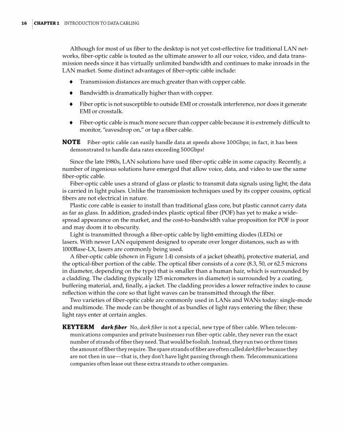
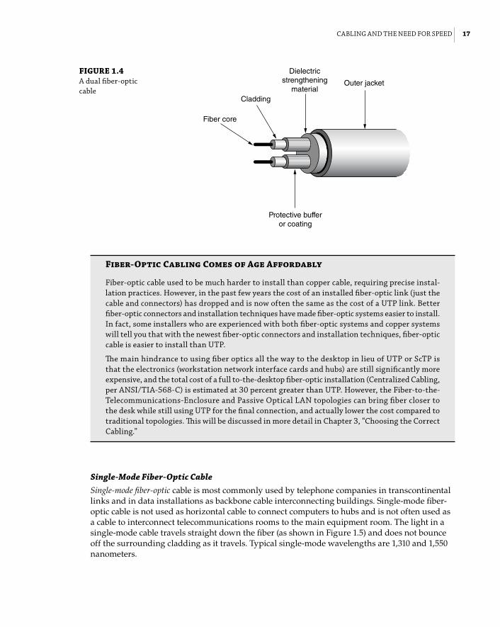
A fiber-optic cable (shown in Figure 1.4) consists of a jacket (sheath), protective material, and the optical-fiber portion of the cable. The optical fiber consists of a core (8.3, 50, or 62.5 microns in diameter, depending on the type) that is smaller than a human hair, which is surrounded by a cladding. The cladding (typically 125 micrometers in diameter) is surrounded by a coating, buffering material, and, finally, a jacket. The cladding provides a lower refractive index to cause reflection within the core so that light waves can be transmitted through the fiber.
Two varieties of fiber-optic cable are commonly used in LANs and WANs today: single-mode and multimode. The mode can be thought of as bundles of light rays entering the fiber; these light rays enter at certain angles.
KEYTERM dark fiber no, dark fiber is not a special, new type of fiber cable. When telecom-munications companies and private businesses run fiber-optic cable, they never run the exact number of strands of fiber they need. That would be foolish. Instead, they run two or three times the amount of fiber they require. The spare strands of fiber are often called dark fiber because they are not then in use—that is, they don’t have light passing through them. telecommunications companies often lease out these extra strands to other companies.
cablIng and the need for Speed | 17
c01.indd 13-02-2014 01:09 PM
FIGuRE 1.4 a dual fiber-optic cable
Outer jacket
Fiber core
Cladding
Protective bufferor coating
Dielectricstrengthening
material
Fiber-Optic Cabling Comes of Age Affordably
fiber-optic cable used to be much harder to install than copper cable, requiring precise instal-lation practices. however, in the past few years the cost of an installed fiber-optic link (just the cable and connectors) has dropped and is now often the same as the cost of a utp link. better fiber-optic connectors and installation techniques have made fiber-optic systems easier to install. In fact, some installers who are experienced with both fiber-optic systems and copper systems will tell you that with the newest fiber-optic connectors and installation techniques, fiber-optic cable is easier to install than utp.
The main hindrance to using fiber optics all the way to the desktop in lieu of utp or Sctp is that the electronics (workstation network interface cards and hubs) are still significantly more expensive, and the total cost of a full to-the-desktop fiber-optic installation (centralized cabling, per anSI/tIa-568-c) is estimated at 30 percent greater than utp. however, the fiber-to-the-telecommunications-enclosure and passive optical lan topologies can bring fiber closer to the desk while still using utp for the final connection, and actually lower the cost compared to traditional topologies. This will be discussed in more detail in chapter 3, “choosing the correct cabling.”
Single-Mode Fiber-Optic CableSingle-mode fiber-optic cable is most commonly used by telephone companies in transcontinental links and in data installations as backbone cable interconnecting buildings. Single-mode fiber-optic cable is not used as horizontal cable to connect computers to hubs and is not often used as a cable to interconnect telecommunications rooms to the main equipment room. The light in a single-mode cable travels straight down the fiber (as shown in Figure 1.5) and does not bounce off the surrounding cladding as it travels. Typical single-mode wavelengths are 1,310 and 1,550 nanometers.

18 | ChAPTER 1 IntroductIon to data cablIng
c01.indd 13-02-2014 01:09 PM
FIGuRE 1.5 Single-mode fiber-optic cable Light source
Light ray
Cladding
Core
Before you install single-mode fiber-optic cable, make sure the equipment you are using sup-ports it. The equipment that uses single-mode fiber typically uses expensive lasers to transmit light through the cable because a laser is the only light source capable of inserting light into the very small (8- to 10-micron) core of a single-mode fiber.
Multimode Fiber-Optic CableMultimode fiber (MMF) optic cable is usually the fiber-optic cable used with networking appli-cations such as 10Base-FL, 100Base-F, FDDI, ATM, Gigabit Ethernet, a10 Gigabit Ethernet, 40 Gigabit Ethernet, and 100 Gigabit Ethernet that require fiber optics for both horizontal and back-bone cable. Multimode cable allows more than one mode (a portion of the light pulse) of light to propagate through the cable. Typical wavelengths of light used in multimode cable are 850 and 1,300 nanometers.
There are two types of multimode fiber-optic cable: step index or graded index. Step-index multimode fiber-optic cable indicates that the refractive index between the core and the clad-ding is very distinctive. The graded-index fiber-optic cable is the most common type of mul-timode fiber. The core of a graded-index fiber contains many layers of glass; each has a lower index of refraction going outward from the core of the fiber. Both types of multimode fiber per-mit multiple modes of light to travel through the fiber simultaneously (see Figure 1.6). Graded-index fiber is preferred because less light is lost as the signal travels around bends in the cable; therefore, the cable offers much greater bandwidth.
FIGuRE 1.6 multimode fiber-optic cable (graded-index multimode)
Light source
Different modesof light exiting
Cladding
Core

cablIng and the need for Speed | 19
c01.indd 13-02-2014 01:09 PM
The typical multimode fiber-optic cable used for horizontal cabling consists of two strands of fiber (duplex); the core is either 50 or 62.5 microns (micrometers) in diameter, and the cladding is 125 microns in diameter (the measurement is often simply referred to as 50/125 micron or 62.5/125 micron).
Coaxial CableAt one time, coaxial (or just coax) cable was the most widely used cable type in the network-ing business. Specifications for coax are now included in ANSI/TIA-568-C.4. This Standard consolidates information from the Residential (RG6 & RG59) and Data Center (Type 734 & 735) Standards. It is still widely used for closed-circuit TV and other video distribution and exten-sively in broadband and CATV applications. However, it is falling by the wayside in the data networking arena. Coaxial cable is difficult to run and is generally more expensive than twisted-pair cable. In defense of coaxial cable, however, it provides a tremendous amount of bandwidth and is not as susceptible to outside interference as is UTP. Overall installation costs might also be lower than for other cable types because the connectors take less time to apply. Although we commonly use coaxial cable to connect our televisions to our set-top boxes, we will probably soon see fiber-optic or twisted-pair interfaces to television set top boxes.
Coaxial cable comes in many different flavors, but the basic design is the same for all types. Figure 1.7 shows a typical coaxial cable; at the center is a solid (or sometimes stranded) cop-per core. Some type of low dielectric insulation material, like fluorinated ethylene-propylene (FEP), polyethylene (PE), or polypropylene (PP), is used to surround the core. Either a sleeve or a braided-wire mesh shields the insulation, and a jacket covers the entire cable.
FIGuRE 1.7 typical coaxial cable
Insulation(PVC or teflon)
Shielding(copper wire mesh
or aluminum sleeve)
Conducting core
Cable jacket
The shielding shown in Figure 1.7 protects the data transmitted through the core from out-side electrical noise and keeps the data from generating significant amounts of interference. Coaxial cable works well in environments where high amounts of interference are common.
A number of varieties of coaxial cable are available on the market. You pick the coaxial cable required for the application; unfortunately, coaxial cable installed for Ethernet cannot be used for an application such an ArcNet. Some common types of coaxial cable are listed in Table 1.1.

20 | ChAPTER 1 IntroductIon to data cablIng
c01.indd 13-02-2014 01:09 PM
TABLE 1.1: common coaxial-cable types
CABLE DESCRIPTION
rg-58 /u a 50 ohm coaxial cable with a solid core. commonly called thinnet and used with 10base-2 ethernet and some cable tv applications.
rg-58 a/u a 50 ohm coaxial cable with a stranded core. also known as thinnet. used by 10base-2 ethernet and some cable tv applications.
rg-58 c/u a military-specification version of rg-58 a/u.
rg-59u a 75 ohm coaxial cable. used with Wang systems and some cable tv applications.
rg-6u a 75 ohm coaxial cable. The current minimum grade to install in residences because it will handle the full frequency range of satellite service, plus high-defini-tion tv and cable-modem service.
rg-6 Quad Shield Same as rg-6u, but with additional shielding for enhanced noise immunity. currently the recommended cable to use in residences.
rg-62u a 93 ohm coaxial cable. used with Ibm cabling systems and arcnet.
Cable DesignWhether you are a network engineer, cable installer, or network manager, a good understanding of the design and components of data cabling is important. Do you know what types of cable can be run above the ceiling? What do all those markings on the cable mean? Can you safely untwist a twisted-pair cable? What is the difference between shielded and unshielded twisted-pair cable? What is the difference between single-mode and multimode fiber-optic cable?
You need to know the answer to these questions—not only when designing or installing a cabling system but also when working with an existing cabling system. All cable types must satisfy some fundamental fire safety requirements before any other design elements are con-sidered. The U.S. National Electrical Code (NEC) defines five levels of cable for use with LAN cabling and telecommunications, shown in Table 1.2. Cables are rated on their flammability, heat resistance, and how much visible smoke (in the case of plenum cable) they generate when exposed to a flame. The ratings are a hierarchy, with limited combustible cables at the top. In other words, a cable with a higher rating can be used instead of any lesser-rated (lower down in the table) cable. For example, a riser cable can be used in place of general-purpose and limited-use cables but cannot be used in place of a plenum cable. A plenum cable can substitute for all those below it.

cable deSIgn | 21
c01.indd 13-02-2014 01:09 PM
TABLE 1.2 nec flame ratings
OPTICAL FIBER ARTICLE 770
TWISTED-PAIR ARTICLE 800
COAxIAL CABLE ARTICLE 820
COMMON TERM NOTES
ofnp1ofcp2 cmp3 mpp4 cavtp plenum most stringent rating. must limit the spread of flame and the generation of visible smoke. Intended for use in hvac (heat-ing, ventilation, and air condi-tioning) plenum areas; can be substituted for all subsequent lesser ratings.
ofnr cmr mpr catvr riser When placed vertically in a building riser shaft going from floor to floor, cable must not transmit flame between floors.
ofcr riser This is a conductive version of ofnr.
ofngofcg cmgmpg catvg general purpose
flame spread limited to 4″–11″ during test. cable may not penetrate floors or ceilings, i.e., may only be used within a single floor. This designation was added as a part of the harmoniza-tion efforts between u.S. and canadian standards.
ofnofc cm catv general purpose
flame spread limited to 4″–11″ during test. cable may not pene-trate floors or ceilings, i.e., may only be used within a single floor.
not applicable cmX catvX limited use
for residential use, but can only be installed in one- and two-family (duplex) housing units. often co-rated with optional ul requirements for limited out-door use.
1 OFN = Optical fiber, nonconductive (no metallic elements in the cable)2 OFC = Optical fiber, conductive (contains a metallic shield for mechanical protection)3 CM = Communications cable4 MP = Multipurpose cable (can be used as a communications cable or a low-voltage signaling cable per NEC
Article 725)

22 | ChAPTER 1 IntroductIon to data cablIng
c01.indd 13-02-2014 01:09 PM
WARNING The 2008 edition of the nec requires that the accessible portion of all abandoned communications cables in plenums and risers be removed when installing new cabling. The cost of doing so could be significant, and your cabling request for quote (rfQ) should clearly state both the requirement and who is responsible for the cost of removal.
NOTE more details on the national electrical code are given in chapter 4, “cable System and Infrastructure constraints.”
PlenumAccording to building engineers, construction contractors, and air-conditioning people, the plenum (shown in Figure 1.8) is the space between the false ceiling (a.k.a. drop-down ceiling) and the structural ceiling, when that space is used for air circulation, heating ventilation, and air-conditioning (HVAC). Occasionally, the space between a false floor (such as a raised computer room floor) and the structural floor is also referred to as the plenum. Typically, the plenum is used for returning air to the HVAC equipment.
FIGuRE 1.8 The ceiling space and a riser
Structural ceilingPlenum
False ceiling
Structural ceilingPlenum
False ceiling
Second floor
First floor
Riser
Wiringcloset
Wiringcloset
Raised ceilings and floors are convenient spaces in which to run data and voice cable, but national code requires that plenum cable be used in plenum spaces. Be aware that some people use the word plenum too casually to refer to all ceiling and floor spaces, whether or not they are plenums. This can be expensive because plenum cables can cost more than twice their non-plenum equivalent. (See the sidebar “Plenum Cables: Debunking the Myths.”)
Cable-design engineers refer to plenum as a type of cable that is rated for use in the plenum spaces of a building. Those of us who work with building engineers, cabling professionals, and contractors must be aware of when the term applies to the air space and when it applies to cable.

cable deSIgn | 23
c01.indd 13-02-2014 01:09 PM
Some local authorities and building management may also require plenum-rated cable in nonplenum spaces. Know the requirements in your locale.
Plenum Cables: Debunking the Myths
It’s time to set the record straight about several commonly held, but incorrect, beliefs about plenum-rated cable. These misconceptions get in the way of most discussions about lan cabling but are especially bothersome in relation to utp.
Myth #1: Any false or drop-ceiling area or space beneath a raised floor is a plenum, and I must use plenum-rated cables there. not true. although many people call all such spaces the plenum, they aren’t necessarily. a plenum has a very specific definition. It is a duct, raceway, or air space that is part of the hvac air-handling system. Sometimes, or even often, the drop-ceiling or raised-floor spaces are used as return air passageways in com-mercial buildings, but not always. Your building maintenance folks should know for sure, as will the company that installed the hvac. If it isn’t a plenum space, then you don’t have to spend the extra for plenum-rated cable.
Myth #2: There are plenum cables and PVC cables. The wording here is nothing but sloppy use of terminology, but it results in the widespread notion that plenum cables don’t use polyvinyl chloride (pvc) in their construction and that nonplenum cables are all pvc. In fact, virtually all four-pair utp cables in the united States use a pvc jacket, plenum cables included. and guess what? no category 5e or better cables on the market use any pvc as an insulation material for the conductors, no matter what the flame rating. So a plenum-rated cable actually has just as much pvc in it as does a so-called pvc nonplenum cable. unless you have to be specific about one of the lesser flame ratings, you are more accurate when you generalize about cable flame ratings if you say plenum and nonplenum instead of plenum and PVC.
Myth #3: Plenum cables don’t produce toxic or corrosive gasses when they burn. In europe and in the united States (regarding specialized installations), much emphasis is placed on “clean” smoke. many tests, therefore, measure the levels of toxic or corrosive elements in the smoke. but for general commercial and residential use, the u.S. philosophy toward fire safety as it relates to cables is based on two fundamentals: first, give people time to evacuate a building and, second, don’t obscure exits and signs that direct people to exits. nec flame-test requirements relate to tests that measure resistance to spreading a fire, to varying degrees and under varying conditions based on intended use of the cable. The requirements satisfy part one of the philosophy—it delays the spread of the fire. because all but plenum cables are intended for installation behind walls or in areas inaccessible to the public, the second part doesn’t apply. however, because a plenum cable is installed in an air-handling space where smoke from the burning cable could spread via hvac fans to the populated part of the building, the plenum test measures the generation of visible smoke. visible smoke can keep people from recognizing exits or suffocate them (which actually happened in some major hotel fires before plenum cables were defined in the code).

24 | ChAPTER 1 IntroductIon to data cablIng
c01.indd 13-02-2014 01:09 PM
Myth #4: I should buy plenum cable if I want good transmission perfor-mance. although fep (fluorinated ethylene-propylene, the conductor insulation material used in plenum-rated category 5e and higher cables) has excellent transmission properties, its use in plenum cables is due more to its equally superb resistance to flame propagation and relatively low level of visible-smoke generation. In category 5e and higher nonplenum cables, hdpe (high-density polyethylene) is commonly used as conductor insulation. It has almost as good transmission properties as fep and has the added benefit of being several times lower in cost than fep (and this explains the primary difference in price between plenum and nonplenum utp cables). hdpe does, however, burn like a candle and generate copious visible smoke. cable manufacturers can adjust the pvc jacket of a four-pair construction to allow an hdpe-insulated cable to pass all flame tests except the plenum test. They also compensate for differences in transmission properties between fep and hdpe (or whatever materials they select) by altering the dimensions of the insulated conductor. end result: no matter what the flame rating, if the cable jacket says category 5e or better, you get category 5e or better.
Myth #5: To really protect my family, I should specify plenum cable be installed in my home. This is unnecessary for two reasons. first, communications cables are almost never the source of ignition or flame spread in a residential fire. It’s not impossible, but it’s extremely rare. Second, to what should the “fireproof” cable be attached? It is going to be fastened to wooden studs, most likely—wooden studs that burn fast, hot, and with much black, poisonous smoke. While the studs are burning, the flooring, roofing, electrical wiring, plastic water pipes, carpets, curtains, furniture, cabinets, and woodwork are also blazing away merrily, generating much smoke as well. a plenum cable’s potential to mitigate such a conflagration is essentially nil. Install a cmX-rated cable, and you’ll comply with the national electric code. Install cm, cmg, or cmr, and you’ll be exceeding nec requirements. leave the cmp cable to the commercial environments for which it’s intended and don’t worry about needing it at home.
RiserThe riser is a vertical shaft used to route cable between two floors. Often, it is nothing more com-plicated than a hole (core) that is drilled in the floor and allows cables to pass through. However, a hole between two floors with cable in it introduces a new problem. In the fire disaster movie The Towering Inferno the fire spread from floor to floor through the building’s cabling. That should not happen nowadays because building codes require that riser cable be rated properly. So the riser cable must have certain fire-resistant qualities.
TIP The national electrical code permits plenum cable to be used in the riser, but it does not allow riser cable to be used in the plenum.
The Towering Inferno had a basis in reality, not only because cables at the time burned rela-tively easily but also because of the chimney effect. A chimney works by drawing air upward, through the fire, invigorating the flames with oxygen flow. In a multistory building, the riser shafts can act as chimneys, accelerating the spread and intensity of the fire. Therefore, building

cable deSIgn | 25
c01.indd 13-02-2014 01:09 PM
codes usually require that the riser be firestopped in some way. That’s accomplished by placing special blocking material in the riser at each penetration of walls or ceilings after the cables have been put in place. Techniques for firestopping are discussed in Chapter 13, “Cabling System Design and Installation.”
General PurposeThe general-purpose rating is for the classic horizontal cable that runs from the wiring closet to the wall outlet. It is rated for use within a floor and cannot penetrate a structural floor or ceiling. It is also the rating most commonly used for patch cords because, in theory, a patch cord will never go through a floor or ceiling. You should be aware that riser-rated cable is most commonly used for horizontal runs, simply because the price difference between riser and general-purpose cables is typically small and contractors don’t want to haul more cable types than they have to.
Limited useThe limited-use rating is for single and duplex (two-family) residences only. Some exceptions in the code allow its use in other environments, as in multitenant spaces such as apartments. However, the exceptions impose requirements that are typically either impractical or aestheti-cally unpleasant, and so it is better to consider limited-use cables as just for single- and two-family residences.
Cable JacketsBecause UTP is virtually ubiquitous in the LAN environment, the rest of this chapter will focus on design criteria and transmission-performance characteristics related to UTP cable.
The best place to start looking at cable design is on the outside. Each type of cable (twisted-pair, fiber optic, or coaxial) will have a different design with respect to the cable covering or the jacket.
KEYTERM jacket and sheath The cable’s jacket is the plastic outer covering of the cable. Sheath is sometimes synonymous with jacket but not always. The sheath includes not only the jacket of the cable but also any outside shielding (such as braided copper or foil) that may surround the inner wire pairs. With utp and most fiber-optic cables, the sheath and the jacket are the same. With Sctp and Stp cables, the sheath includes the outer layer of shielding on the inner wires.
One of the most common materials used for the cable jacket is polyvinyl chloride (PVC); UTP cables in the United States are almost exclusively jacketed with PVC, regardless of the flame rating of the cable. PVC was commonly used in early LAN cables (Category 3 and lower) as an insulation and as material for jackets, but the dielectric properties of PVC are not as desirable as those of other thermoplastics, such as FEP or PP, that can be used for higher-frequency trans-mission. Figure 1.9 shows a cutaway drawing of a UTP cable.
Other substances commonly used in cable jackets of indoor cables include ECTFE (HALAR), PVDF (KYNAR), and FEP (Teflon or NEOFLON). These materials have enhanced flame-retardant qualities as compared to PVC but are much more costly. Where PVC can do the job, it’s the jacket material of choice.

26 | ChAPTER 1 IntroductIon to data cablIng
c01.indd 13-02-2014 01:09 PM
FIGuRE 1.9 cutaway drawing of a utp cable show-ing insulated wire pairs, slitting cord, and jacket
Jacket
Slitting cord made of nylonor other polymer
Twisted pairs—each wire’s insulationis color coded.
KEYTERM rip cord Inside some utp cable jackets is a polyester or nylon string called the rip cord, also known as the slitting cord or slitting string. The purpose of this cord is to assist with slicing the jacket open when more than an inch or two of jacket needs to be removed. Some cable installers love them; many find them a nuisance, as they get in the way during termination.
NOTE no standard exists for the jacket color, so manufacturers can make the jacket any color they care to. You can order category 5e or 6 cables in at least a dozen different colors. colors like hot pink and bright yellow don’t function any differently than plain gray cables, but they sure are easier to spot when you are in the ceiling! many cable installers will pick a different color cable based on which jack position or patch panel the cable is going to so that it is easier to identify quickly.
Cable MarkingsHave you examined the outside jacket of a twisted-pair or fiber-optic cable? If so, you noticed many markings on the cable that may have made sense. UL has requirements on how their desig-nations are applied and the FCC requires that the category be placed every foot. For cables manu-factured for use in the United States and Canada, these markings may identify the following:
♦♦ Cable manufacturer and manufacturer part number.
♦♦ Category of cable (e.g., UTP).
♦♦ NEC/UL flame tests and ratings.
♦♦ CSA (Canadian Standards Association) flame tests.
♦♦ Footage indicators. Sometimes these are “length-remaining markers” that count down from the package length to zero so you can see how many feet of cable remains on a spool or in a box. Superior Essex (www.superioressex.com) is one cable manufacturer that imprints length-remaining footage indicators.

cable deSIgn | 27
c01.indd 13-02-2014 01:09 PM
For a list of definitions of some marking acronyms, see the next section, “Common Abbreviations.”
Here is an example of one cable’s markings:
000750 FT 4/24 (UL) c(UL) CMP/MPP VERIFIED (UL) CAT 5e SUPERIOR ESSEX COBRA 2456590.5H
These markings identify the following information about the cable:
♦♦ The 000750 FT is the footage indicator.
♦♦ The 4/24 identifies the cable as having four pairs of 24 AWG wire.
♦♦ The (UL) symbol indicates that the cable is UL listed. Listing is a legal requirement of the NEC.
♦♦ The symbol c(UL) indicates that the cable is UL listed to Canadian requirements in addi-tion to U.S. requirements. Listing is a legal requirement of the CSA.
♦♦ The CMP/MPP code stands for communications plenum (CMP) and multipurpose plenum (MPP) and indicates that the cable can be used in plenum spaces. This is the NEC flame/smoke rating.
♦♦ The term VERIFIED (UL) CAT 5e means that the cable has been verified by the UL as being Category 5e compliant (and TIA/EIA-568-C compliant). Verification to transmission prop-erties is optional.
♦♦ SUPERIOR ESSEX is the manufacturer of the cable.
♦♦ COBRA is the cable brand (in this case, a Category 5e–plus cable, which means it exceeds the requirements for Category 5e).
♦♦ The numbers 2456590.5 indicate the date of manufacture in Julian format. In this case, it is the 25th day of October 2013.
♦♦ H indicates the Superior Essex manufacturing plant.
Some manufacturers may also include their “E-file” number instead of the company name. This number can be used when calling the listing agency (such as the UL) to trace the manufac-turer of a cable. In the case of UL, you can look up the E-file numbers online at www.ul.com.
WARNING cables marked with CMR (communications riser) and CMG (communications general) must not be used in the plenum spaces.
Common AbbreviationsSo that you can better decipher the markings on cables, here is a list of common acronyms and what they mean:
NFPA The National Fire Protection Association
NEC The National Electrical Code that is published by the NFPA once every 3 years
UL The Underwriters Laboratories
CSA The Canadian Standards Association
PCC The Premise Communication Cord standards for physical wire tests defined by the CSA

28 | ChAPTER 1 IntroductIon to data cablIng
c01.indd 13-02-2014 01:09 PM
Often, you will see cables marked with NFPA 262, FT-4, or FT-6. The NFPA 262 (formerly UL-910) is the test used for plenum cables. The FT-4 is the CSA equivalent of UL 1666 or the riser test, and FT-6 is the CSA equivalent of NFPA 262.
Wire InsulationInside the cable jacket are the wire pairs. The material used to insulate these wires must have a very low dielectric constant and low dissipation factor. Refer back to Figure 1.9 for a diagram of the wire insulation.
KEYTERM dielectric and dissipation factor a material that has good dielectric properties is a poor conductor of electricity. dielectric materials are insulators. In the case of lan cables, a good dielectric material also has characteristics conducive to the transmission of high-frequency signals along the conductors. The dissipation factor is the measure of loss-rate of power and becomes the dominant factor for signal loss at high frequencies.
Materials used for Wire InsulationA variety of insulating materials exists, including polyolefin (polyethylene and polypropylene), fluorocarbon polymers, and PVC.
The manufacturer chooses the materials based on the material cost, flame-test ratings, and desired transmission properties. Materials such as polyolefin are inexpensive and have great transmission properties, but they burn like crazy, so they must be used in combination with material that has better flame ratings. That’s an important point to keep in mind: don’t focus on a particular material. It is the material system selected by the manufacturer that counts. A manufacturer will choose insulating and jacketing materials that work together according to the delicate balance of fire resistance, transmission performance, and economics.
The most common materials used to insulate the wire pairs in Category 5e and greater ple-num-rated cables are fluorocarbon polymers. The two varieties of fluorocarbon polymers used are fluorinated ethylene-propylene (FEP) and perfluoroalkoxy (PFA).
These polymers were originally developed by DuPont and are also sometimes called by their trademark, Teflon. The most commonly used and most desirable of these materials is FEP. Over the past few years, the demand for plenum-grade cables exceeded the supply of available FEP. During periods of FEP shortage, Category 5e plenum designs emerged that substituted another material for one or more of the pairs of wire. In addition, some instances of marginal performance occurred in the UL-910 burn test for plenum cables. These concerns, coupled with increases in the supply of FEP and substitutes like MFA, have driven these designs away.
TIP When purchasing category 5e and higher plenum cables, ask whether other insulation material has been used in combination with fep for wire insulation.
In nonplenum Category 5e and higher and in the lower categories of cable, much less expen-sive and more readily available materials, such as HDPE (high-density polyethylene), are used. You won’t sacrifice transmission performance; the less stringent flame tests just allow less expensive materials.

cable deSIgn | 29
c01.indd 13-02-2014 01:09 PM
Insulation ColorsThe insulation around each wire in a UTP cable is color-coded. The standardized color codes help the cable installer make sure each wire is connected correctly with the hardware. In the United States, the color code is based on 10 colors. Five of these are used on the tip conductors, and five are used on the ring conductors. Combining the tip colors with the ring colors results in 25 possible unique pair combinations. Thus, 25 pair groups have been used for telephone cables for decades.
NOTE The words tip and ring hark back to the days of manual switchboards. phono-type plugs (like the ones on your stereo headset cord) were plugged into a socket to connect one extension or number to another. The plug had a tip, then an insulating disk, and then the shaft of the plug. one conductor of a pair was soldered into the tip and the other soldered to the shaft, or ring. remnants of this 100-year-old technology are still with us today.
Table 1.3 lists the color codes found in a binder group (a group of 25 pairs of wires) in larger-capacity cables. The 25-pair cable is not often used in data cabling, but it is frequently used for voice cabling for backbone and cross-connect cable.
TABLE 1.3: color codes for 25-pair utp binder groups
PAIR NuMBER TIP COLOR RING COLOR
1 White blue
2 White orange
3 White green
4 White brown
5 White Slate
6 red blue
7 red orange
8 red green
9 red brown
10 red Slate
11 black blue
12 black orange
13 black green
14 black brown

30 | ChAPTER 1 IntroductIon to data cablIng
c01.indd 13-02-2014 01:09 PM
PAIR NuMBER TIP COLOR RING COLOR
15 black Slate
16 Yellow blue
17 Yellow orange
18 Yellow green
19 Yellow brown
20 Yellow Slate
21 violet blue
22 violet orange
23 violet green
24 violet brown
25 violet Slate
With LAN cables, it is common to use a modification to this system known as positive identifi-cation. PI, as it is sometimes called, involves putting either a longitudinal stripe or circumferen-tial band on the conductor in the color of its pair mate. In the case of most four-pair UTP cables, this is usually done only to the tip conductor because each tip conductor is white, whereas the ring conductors are each a unique color.
Table 1.4 lists the color codes for a four-pair UTP cable. The PI color is indicated after the tip color.
TABLE 1.4: color codes for four-pair utp cable
PAIR NuMBER TIP COLOR RING COLOR
1 White/blue blue
2 White/orange orange
3 White/green green
4 White/brown brown
TABLE 1.3: color codes for four-pair utp cable (continued)

cable deSIgn | 31
c01.indd 13-02-2014 01:09 PM
Waiter! There’s halogen in My Cable!
much of the cable currently in use in the united States and elsewhere in the world contains halogens. a halogen is a nonmetallic element, such as fluorine, chlorine, iodine, or bromine. When exposed to flames, substances made with halogens give off toxic fumes that quickly harm the eyes, nose, lungs, and throat. did you notice that fluorine and chlorine are commonly found in cable insulation and jackets? even when cables are designed to be flame-resistant, any cable when exposed to high enough temperatures will melt and burn. pvc cables contain chlorine, which emits toxic fumes when burned.
many different manufacturers are now making low-smoke, zero-halogen (lSZh or lS0h) cables. These cables are designed to emit no toxic fumes and produce little or no smoke when exposed to flames. tunnels, enclosed rooms, aircraft, and other minimum-ventilation areas are prime spots for the use of lSZh cables because those areas are more difficult to escape from quickly.
lSZh cables are popular outside the united States. Some safety advocates are calling for the use of lSZh cables in the united States, specifically for the plenum space. review your local building codes to determine if you must use lSZh cable. non-lSZh cables will produce corrosive acids if they are exposed to water (such as from a sprinkler system) when burned; such acids may theoretically further endanger equipment. but many opponents of lSZh cable reason that if an area of the building is on fire, the equipment will be damaged by flames before it is damaged by corrosives from a burning cable.
Why, you might ask, would anyone in his or her right mind argue against the installation of lSZh cables everywhere? first, reducing toxic fumes doesn’t necessarily mean the cable is more fireproof. The flame-spread properties are worse than for cables in use today. numerous studies by bell labs showed that cables composed of lSZh will not pass the plenum test, not because of smoke generation but because of flame spread. most lSZh cable designs will only pass the riser test where the allowable flame spread is greater. Second, consider practicality. lSZh is an expensive solution to a problem that doesn’t seem to exist in the united States.
TwistsWhen you slice open a UTP communications cable, you will notice that the individual conduc-tors of a pair of wire are twisted around one another. At first, you may not realize how impor-tant these twists are.
TIP did you know that in category 5e cables a wire pair untwisted more than half of an inch can adversely affect the performance of the entire cable?
Twisted-pair cable is any cable that contains a pair of wires that are wrapped or twisted around one another between 2 and 12 times per foot—and sometimes even more than 12 times per foot (as with Category 5e and higher). The twists help to cancel out the electromagnetic interference (EMI) generated by voltage used to send a signal over the wire. The interference can cause problems, called crosstalk, for adjacent wire pairs. Crosstalk and its effects are discussed in the “Speed Bumps: What Slows Down Your Data” section later in this chapter.
Cables commonly used for patch cables and for horizontal cabling (patch panel to wall plate) typically contain four pairs of wires. The order in which the wires are crimped or punched down is very important.

32 | ChAPTER 1 IntroductIon to data cablIng
c01.indd 13-02-2014 01:09 PM
TIP companies such as panduit (www.panduit.com) and leviton (www.leviton.com) have developed termination tools and patch cables that all but eliminate the need to untwist cables more than a tiny amount.
Wire GaugeCopper-wire diameter is most often measured by a unit called AWG (American Wire Gauge). Contrary to many other measuring systems, as the AWG number gets smaller, the wire diameter actually gets larger; thus, AWG 24 wire is smaller than AWG 22 wire. Larger wires are useful because they have more physical strength and lower resistance. However, the larger the wire diameter, the more copper is required to make the cable. This makes the cable heavier, harder to install, and more expensive.
NOTE The reason the aWg number increases as the wire diameter decreases has to do with how wire is made. You don’t dump copper ore into a machine at one end and get 24 aWg wire out the other end. a multistep process is involved—converting the ore to metal, the metal to ingots, the ingots to large bars or rods. rods are then fed into a machine that makes them into smaller-diameter rods. to reach a final diameter, the rod is pulled through a series of holes, or dies, of decreasing size. going through each die causes the wire to stretch out a little bit, reduc-ing its diameter. historically, the aWg number represented the exact number of dies the wire had to go through to get to its finished size. So, the smaller the wire, the more dies involved and the higher the aWg number.
The cable designer’s challenge is to use the lowest possible diameter wire (reducing costs and installation complexity) while at the same time maximizing the wire’s capabilities to support the necessary power levels and frequencies.
Category 5e UTP is always 24 AWG; IBM Type 1A is typically 22 AWG. Patch cords may be 26 AWG, especially Category 3 patch cords. The evolution of higher-performance cables such as Category 6 and Category 6A has resulted in 23 AWG often being substituted for 24 AWG. Table 1.5 shows 22, 23, 24, and 26 AWG sizes along with the corresponding diameter, area, and weight per kilometer.
TABLE 1.5: american Wire gauge diameter, area, and weight values
AWG
NOMINAL DIAMETER (INChES)
NOMINAL DIAMETER (MM)
CIRCuLAR-MIL (CM)
AREA (Sq. MM)
WEIGhT (KG/KM)
22 0.0253 0.643 640.4 0.3256 2.895
23 0.0226 0.574 511.5 0.2581 2.295
24 0.0201 0.511 404.0 0.2047 1.820
26 0.0159 0.404 253.0 0.1288 1.145

cable deSIgn | 33
c01.indd 13-02-2014 01:09 PM
The dimensions in Table 1.5 were developed more than 100 years ago. Since then, the purity and therefore the conductive properties of copper have improved due to better copper-processing techniques. Specifications that cover the design of communications cables have a waiver on the actual dimensions of a wire. The real concern is not the dimensions of the wire, but how it performs, specifically with regard to resistance in ohms. The AWG standard indicates that a 24 AWG wire will have a diameter of 0.0201″, but based on the performance of the material, the actual diameter of the wire may be slightly less or slightly more (but usually less).
Solid Conductors vs. Stranded ConductorsUTP cable used as horizontal cable (permanent cable or cable in the walls) has a solid conduc-tor, as opposed to patch cable and cable that is run over short distances, which usually have stranded conductors. Stranded-conductor wire consists of many smaller wires interwoven together to form a single conductor.
TIP connector types (such as patch panels and modular jacks) for solid-conductor cable are dif-ferent than those for stranded-conductor cable. Stranded-conductor cables will not work with insulated displacement connector (Idc)-style connectors found on patch panels and 66-style punch-down blocks.
Though stranded-conductor wire is more flexible, solid-conductor cable has much better elec-trical properties. Stranded-conductor wire is subject to as much as 20 percent more attenuation (loss of signal) due to a phenomenon called skin effect. At higher frequencies (the frequencies used in LAN cables), the signal current concentrates on the outer circumference of the overall conductor. Since stranded-conductor wire has a less-defined overall circumference (due to the multiple strands involved), attenuation is increased.
KEYTERM core The core of the cable is anything found inside the sheath. The core is usually just the insulated twisted pairs, but it may also include a slitting cord and the shielding over in-dividual twisted pairs in an Stp cable. people incorrectly refer to the core of the cable when they mean the conductor (the element that conducts the electrical signal).
Most cabling standards recommend using solid-conductor wire in the horizontal or perma-nent portion of the link, but the standards allow for stranded-conductor wire in patch cables where flexibility is more important. We know of several UTP installations that have used stranded-conductor wires for their horizontal links. Although we consider this a poor practice, here are some important points to keep in mind if you choose to use a mixture of these cables:
♦♦ Stranded-conductor wire requires different connectors.
♦♦ Stranded-conductor wires don’t work as well in punch-down blocks designed for solid-conductor cables.
♦♦ You must account for reduced horizontal-link distances.
Cable LengthThe longer the cable, the less likely the signal will be carried completely to the end of the cable because of noise and signal attenuation. Realize, though, that for LAN systems the time it takes

34 | ChAPTER 1 IntroductIon to data cablIng
c01.indd 13-02-2014 01:09 PM
for a signal to get to the end is also critical. Cable design engineers are now measuring two addi-tional performance parameters of cable: the propagation delay and the delay skew. Both parameters are related to the speed at which the electrons can pass through the cable and the length of the wire pairs in the cable. The variables are discussed in the “Speed Bumps: What Slows Down Your Data” section later in this chapter.
Cable Length vs. Conductor LengthA Category 5e, 6, 6A, 7, or 7A cable has four pairs of conductors. By design, each of the four pairs is twisted in such a fashion that the pairs are slightly different lengths. Varying twist lengths from pair to pair improves crosstalk performance. Therefore, signals transmitted simultane-ously on two different pairs of wire will arrive at slightly different times. The conductor length is the length of the individual pair of conductors, whereas the cable length is the length of the cable jacket.
Part of a modern cable tester’s feature set is the ability to perform conductor-length tests. Here is a list of the conductor lengths of a cable whose cable length is 139′ from the wall plate to the patch panel. As you can see, the actual conductor length is longer due to the twists in the wire.
PAIR DISTANCE
1-2 145′
3-6 143′
4-5 141′
7-8 142′
Warp Factor One, Please
light travels almost 300,000,000 meters per second in a perfect vacuum, faster than nonphysi-cists can imagine. In a fiber-optic cable 1 kilometer long, data can travel from start to finish in about 3.3 microseconds (0.0000033 seconds).
data does not travel through copper cabling quite as fast. one of the ways that the speed of data through a copper cable is measured is by how fast electricity can travel through the cable. This value is called the nominal velocity of propagation (nvp) and is expressed as a percentage of the speed of light. The value for most cables is between 60 and 90 percent. The cable manufacturer specifies nvp as part of the cable’s design.
take, for example, a cable that was recently measured using a handheld cable tester. The nvp for this cable was 67 percent, and the cable was 90 meters long. electricity will travel through this cable at a speed of about 200,000,000 meters per second; it travels from one end of the cable to another in 450 nanoseconds (0.00000045 seconds).

data communIcatIonS 101 | 35
c01.indd 13-02-2014 01:09 PM
Data Communications 101Before we discuss more of the limitations involved with data communications and network cabling, some basic terms must be defined. Unfortunately, vendors, engineers, and network managers serve up high-tech and communications terms like balls in a tennis match. Worse, they often misuse the terms or don’t even fully understand what they mean.
One common term is bandwidth. Does it mean maximum frequency or maximum data rate? Other terms, including impedance, resistance, and capacitance, are thrown at you as if you have a PhD in electrical engineering.
Our favorite misunderstood term is decibels. We always thought decibels were used to mea-sure sound, but that’s not necessarily true when it comes to data communications. Over the next few pages, we will take you through a crash course in Data Communications 101 and get you up to speed on certain terms pertaining to cabling.
Bandwidth, Frequency, and Data RateOne initially confusing aspect about cabling is that cables are rated in hertz rather than bits per second. Network engineers (and you, presumably) are more concerned with how much data can be pushed through the cable than with the frequency at which that data is traveling.
Frequency is the number of cycles completed per unit of time and is generally expressed in hertz (cycles per second). Figure 1.10 shows a cycle that took one second to complete; this is one hertz. Data cabling is typically rated in kilohertz (kHz) or megahertz (MHz). For a cable rated at 100MHz, the cycle would have to complete 100,000,000 times in a single second! The more cycles per second, the more noise the cable generates and the more susceptible the cable is to signal-level loss.
FIGuRE 1.10 one cycle every sec-ond or one hertz
+
–
One complete cycle
1 second
0
Vol
tage
The bandwidth of a cable is the maximum frequency at which data can be effectively transmitted and received. The bit rate is dependent on the network electronics, not the cable, provided the operating frequency of the network is within the cable’s usable bandwidth. Put another way, the cable is just a pipe. Think of the bandwidth as the pipe’s diameter. Network electronics provide the water pressure. Either a trickle comes through or there’s a gusher, but the pipe diameter doesn’t change.
Cable bandwidth is a difficult animal to corral. It is a function of three interrelated, major elements: distance, frequency, and signal-level-to-noise-level ratio (SNR). Changing any one ele-ment alters the maximum bandwidth available. As you increase the frequency, SNR gets worse,

36 | ChAPTER 1 IntroductIon to data cablIng
c01.indd 13-02-2014 01:09 PM
and the maximum bandwidth is decreased. As you increase distance, SNR worsens, thereby decreasing the maximum bandwidth. Conversely, reducing frequency or distance increases the maximum bandwidth because SNR improves.
To keep the same maximum bandwidth, increasing the frequency means you must either decrease distance or improve the signal level at the receiver. If you increase the distance, either the frequency must decrease, or, again, the signal level at the receiver must improve. If you improve signal level at the receiving end, you can either increase frequency or leave the fre-quency alone and increase distance. It’s a tough bronco to ride.
Standards Provide a Structured ApproachWith all this variability, how do you get anywhere with cable and network design? It helps to lasso one or more of the variables.
This is done for you via the IEEE network specifications and implemented through ANSI/TIA-568-C. A maximum horizontal run length of 100 meters (308′), including workstation and communication closet patch cords, is specified. This figure arises from some timing limitations of some Ethernet implementations. So distance is fixed.
The standards also define the maximum operating frequency. In the case of Category 3 cables, it is 16MHz. In the case of 5e, it is 100MHz; for Category 6, 250 MHz; for Category 6A, 500 MHz; for Category 7, 600 MHz; and for Category 7A, 1,000 MHz.
Now that two of the three elements are firmly tied to the fence, you can rope in the last. Cable design focuses on improving the signal level and reducing the noise in the cable to achieve opti-mum transmission performance for given frequencies at a fixed length.
“Huh?” you may be saying to yourself. “That implies I could have horizontal run lengths greater than 100 meters if I’m willing to lower my bandwidth expectations or put up with a lower signal level. I thought 100 meters was the most a Category 5e (or better) cable could run.” According to the standard, 100 meters is the maximum. But technically, the cabling might be able to run longer. Figure 1.11 unhitches length and instead ties down frequency and SNR. In the graph, the frequency at which the signal and noise level coincide (the “ACR=0” point) is plot-ted against distance. You can see that if the signal frequency is 10MHz, a Category 5e cable is capable of carrying that signal almost 2,500′, well beyond the 100 meter (308′) length specified.
So why not do so? Because you’d be undermining the principle of structured wiring, which requires parameters that will work with many LAN technologies, not just the one you’ve got in mind for today. Some network architectures wouldn’t tolerate it, and future upgrades might be impossible. Stick to the 100 meter maximum length specified.
The data rate (throughput or information capacity) is defined as the number of bits per second that move through a transmission medium. With some older LAN technologies, the data rate has a one-to-one relationship with the transmission frequency. For example, 4Mbps Token Ring operates at 4MHz.
It’s tough to keep pushing the bandwidth of copper cables higher and higher. There are the laws of physics to consider, after all. So techniques have been developed to allow more than 1 bit per hertz to move through the cable. Table 1.6 compares the operating frequency of transmission with the throughput rate of various LAN technologies available today.
All the systems listed in the table except the last (which requires Category 6A cable) will work with Category 5 or higher cable. So how do techniques manage to deliver data at 1Gbps across a Category 5e cable whose maximum bandwidth is 100MHz? The next section gives you the answer.

data communIcatIonS 101 | 37
c01.indd 13-02-2014 01:09 PM
FIGuRE 1.11 The frequency at which the signal and noise level coin-cide (acr=0 point) plotted against distance
Freq
uenc
y, M
Hz
ACR = 0 Limited Bandwidth
Length, Feet
10 500 1000 1500 2000 2500 3000 3500
10
100
1000
Category 3
Category 5
TABLE 1.6: lan throughput vs. operating frequency
LAN SYSTEM DATA RATE OPERATING FREquENCY
token ring 4mbps 4mhz
10base-t ethernet 10mbps 10mhz
token ring 16mbps 16mhz
100baset ethernet 100mbps 31.25mhz
atm 155 155mbps 38.75mhz
1000base-t (gigabit) ethernet 1,000mbps approximately 65mhz
10gbase-t (10gb) ethernet 10,000 mbps approximately 400mhz
The Secret Ingredient: Encoding and Multipair Simultaneous Send and ReceiveConsider the example illustrated in Figure 1.12. A street permits one car to pass a certain stretch of road each second. The cars are spaced a certain distance apart, and their speeds are limited so that only one is on the stretch of road at a time.

38 | ChAPTER 1 IntroductIon to data cablIng
c01.indd 13-02-2014 01:09 PM
FIGuRE 1.12 a street that allows one car to pass each second
Only a single car can pass through each second.
1 second
But suppose that (as in Figure 1.13) the desired capacity for this particular part of the street is three cars per second. The cars can drive faster, and they can be spaced so that three at a time fit on the stretch of road. This is bit encoding. It is a technology for packing multiple data bits in each hertz to increase throughput.
FIGuRE 1.13 a street that allows multiple cars through during each cycle
Allows three cars to pass through each second. That’s encoding!
1 second
Car 1 Car 2 Car 3
Add a lane in each direction, and you can see how most LAN technologies work today. They use two of the four pairs of cable, one to transmit and one to receive—effectively, a two-lane highway.
At some point, though, a limit will be reached as to how fast the cars can travel. Plus, eventu-ally the cars will be packed end-to-end in a lane and we just won’t be able to fit any more cars (data bits) through that stretch in the available time.
What to do? How about building multiple lanes? Instead of using two lanes, one in each direction, four lanes (four pairs of cable) would ease the congestion.
Four lanes still might not be enough capacity to get all the cars needed down the highway. So all four lanes will be used, but instead of two being dedicated to send and two to receive, the cars will drive both directions in every lane. It takes accurate timing and nerves of steel, but it can be done. This is, in fact, how Gigabit Ethernet is implemented on Category 5e and higher cabling. Transmitting at an operating frequency of about 65MHz, data is simultaneously sent and received on all four pairs at a rate of 250Mbps each. Voilà! That’s 1,000Mbps in less than 100MHz of bandwidth!
TIP for gigabit ethernet to work over category 5e, 6, and 6a cabling, all four pairs must be used. The same is true for 10 gigabit ethernet: all four pairs must be used in a category 6a, 7, or 7a cable.
What a Difference a dB Makes!Suppose you are comparing cable performance. A manufacturer states that the attenuation (power loss) for a cable with a length of 90 meters, operating at 100MHz, is 20dB. What does the measurement mean? Would you be surprised to learn that the signal strength has dropped by a factor of 100? That’s right; if you apply an input power level of 5 watts, the output level will be 0.05 watts! For every 3dB of attenuation, it’s a 50 percent loss of power!

data communIcatIonS 101 | 39
c01.indd 13-02-2014 01:09 PM
To summarize: Low decibel values of attenuation are desirable because then less of the signal is lost on its way to the receiver. Higher decibel values of crosstalk (NEXT, ACR-F, PS ACR-F, etc.) and return loss are actually desirable because that means less signal has been measured on adjacent wires. (For more on NEXT, ACR-F, and PS ACR-F, see “Noise (Signal Interference)” later in this chapter.)
This section may be all you ever wanted to know about decibels. If you want to know more and get the technical details, read on!
Digging a Little Deeper into DecibelsYou may think of a decibel in terms of audible noise. When referring to the domain of sound, a decibel is not actually a specific unit of measurement but rather is used to express a ratio of sound pressure.
However, the decibel is also commonly used when defining attenuation, crosstalk, and return loss. Just as with sound, when referring to communications and electrical transmis-sion performance, the decibel is a ratio rather than a specific measurement. Because analog and digital communication signals are just electrical energy instead of sound pressure, the dB unit is a ratio of input power to output power. The decibel value is independent of the actual input and output voltage or power and is thus considered a generic performance specification. Understanding what the decibel numbers mean is important when comparing one cabling media or performance measurement with another.
Decibels 101The bel part of decibel was named after Alexander Graham Bell, the inventor of the telephone. A decibel is a tenfold logarithmic ratio of power (or voltage) output to power (or voltage) input. Keep in mind that the decibel is indicating a power ratio, not a specific measurement. The deci-bel is a convenient way to reflect the power loss or gain, regardless of the actual values.
NOTE for measurements such as attenuation, neXt, acr-f, and return loss, the decibel value is always negative because it represents a loss, but often the negative sign is ignored when the measurement is written. The fact that the number represents a loss is assumed.
Cable testers as well as performance specifications describe attenuation in decibels. Let’s say, for example, that you measure two cables of identical length and determine that the attenuation is 15dB for one cable and 21dB for the other. Naturally, you know that because lower attenuation is better, the cable with an attenuation of 15dB is better than the one with a 21dB value. But how much better? Would you be surprised to learn that even though the difference between the two cables is only 6dB, there is 50 percent more attenuation of voltage or amperage (power is calcu-lated differently) on the cable whose attenuation was measured at 21dB?
Knowing how a decibel is calculated is vital to appreciating the performance specifications that the decibel measures.
Decibels and PowerWhen referring to power (watts), decibels are calculated in this fashion:
dB = 10 × log10(P1/P2)
P1 indicates the measured power, and P2 is the reference power (or input power).To expand on this formula, consider this example. The reference power level (P2) is 1.0 watts.
The measured power level (P1) on the opposite side of the cable is 0.5 watts. Therefore, through this

40 | ChAPTER 1 IntroductIon to data cablIng
c01.indd 13-02-2014 01:09 PM
cable, 50 percent of the signal was lost due to attenuation. Now, plug these values into the power formula for decibels. Doing so yields a value of 3dB. What does the calculation mean? It means that:
♦♦ Every 3dB of attenuation translates into 50 percent of the signal power being lost through the cable. Lower attenuation values are desirable, as a higher power level will then arrive at the destination.
♦♦ Every 3dB of return loss translates into 50 percent less signal power being reflected back to the source. Higher decibel values for return loss are desirable, as less power will then be returned to the sender.
♦♦ Every 3dB of NEXT translates into 50 percent less signal power being allowed to couple to adjacent pairs. Higher decibel values for NEXT (and other crosstalk values) are desirable, since higher values indicate that less power will then couple with adjacent pairs.
An increase of 10dB means a tenfold increase in the actual measured parameter. Table 1.7 shows the logarithmic progression of decibels with respect to power measurements.
TABLE 1.7: logarithmic progression of decibels
DECIBEL VALuE ACTuAL INCREASE IN MEASuRED PARAMETER
3db 2
10db 10
20db 100
30db 1,000
40db 10,000
50db 100,000
60db 1,000,000
Decibels and VoltageMost performance specifications and cable testers typically reference voltage ratios, not power ratios. When referring to voltage (or amperage), decibels are calculated slightly differently than for power. The formula is as follows:
dB = 20 × log10(P1/P2)
P1 indicates the measured voltage or amperage, and P2 is the reference (or output) voltage (amperage). Substituting a reference value of 1.0 volt for P2 and 0.5 volts for P1 (the measured output), you get a value of –6dB. What does the calculation mean? It means that:
♦♦ Every 6dB of attenuation translates into 50 percent of the voltage being lost to attenuation. Lower decibel attenuation values are desirable, because a higher voltage level will then arrive at the destination.

data communIcatIonS 101 | 41
c01.indd 13-02-2014 01:09 PM
♦♦ Every 6dB of return loss translates into 50 percent less voltage being reflected back to the source. Higher decibel values for return loss are desirable, because less voltage will then be returned to the sender.
♦♦ Every 6dB of NEXT translates into 50 percent less voltage coupling to adjacent wire pairs. Higher decibel values for NEXT (and other crosstalk values) are desirable, because higher values indicate that less power will then couple with adjacent pairs.
Table 1.8 shows various decibel levels and the corresponding voltage and power ratios. Notice that (for the power ratio) if a cable’s attenuation is measured at 10dB, only one-tenth of the signal transmitted will be received on the other side.
TABLE 1.8: decibel levels and corresponding power and voltage ratios
DB VOLTAGE RATIO POWER RATIO
1 1 1
–1 0.891 0.794
–2 0.794 0.631
–3 0.707 0.500
–4 0.631 0.398
–5 0.562 0.316
–6 0.500 0.250
–7 0.447 0.224
–8 0.398 0.158
–9 0.355 0.125
–10 0.316 0.100
–12 0.250 0.063
–15 0.178 0.031
–20 0.100 0.010
–25 0.056 0.003
–30 0.032 0.001
–40 0.010 0.000
–50 0.003 0.000

42 | ChAPTER 1 IntroductIon to data cablIng
c01.indd 13-02-2014 01:09 PM
Applying Knowledge of DecibelsNow that you have a background on decibels, look at the specified channel performance for Category 5e versus the channel performance for Category 6 cable at 100MHz.
MEDIA TYPE ATTENuATION NExT RETuRN LOSS
category 5e 24 30.1 10.0
category 6 21.3 39.9 12.0
For the values to be meaningful, you need to look at them with respect to the actual percent-age of loss. For this example, use voltage. If you take each decibel value and solve for the P1/P2 ratio using this formula, you would arrive at the following values:
Ratio = 1 / (Inverse log10(dB/20))
MEDIA
REMAINING SIGNAL DuE TO ATTENuATION
ALLOWED TO COuPLE (NExT)
SIGNAL RETuRNED (NExT)
category 5e 6.3% 3.1% 39.8%
category 6 8.6% 1% 31.6%
Existing standards allow a transmission to lose 99 percent of its signal to attenuation and still be received properly. For an Ethernet application operating at 2.5 volts of output voltage, the measured voltage at the receiver must be greater than 0.025 volts. In the Category 5e cable example, only 6.3 percent of the voltage is received at the destination, which calculates to about 0.16. For Category 6 cable it calculates to 0.22 volts, almost 10 times the minimum required volt-age for the signal to be received.
Using such techniques for reversing the decibel calculation, you can better compare the per-formance of any media.
Speed Bumps: What Slows Down Your DataThe amount of data that even simple unshielded twisted-pair cabling can transfer has come a long way over the past dozen or so years. In the late 1980s, many experts felt that UTP cabling would never support data rates greater than 10Mbps. Today, data rates of 10Gbps are supported over cable lengths of 100 meters! And UTP may be able to support even greater data rates in the future.
Think back to the MIS director who mistakenly assumed “it is just wire.” Could he be right? What is the big deal? Shouldn’t data cabling be able to support even higher data rates?
Have you tried to purchase data-grade cable recently? Have you ever tested a cable run with an even mildly sophisticated cable tester? A typical cabling catalog can have over 2,000 differ-ent types of cables! You may have come away from the experience wondering if you needed a degree in electrical engineering in order to understand all the terms and acronyms. The world of modern cabling has become a mind-boggling array of communications buzzwords and engi-neering terms.

Speed bumpS: What SloWS doWn Your data | 43
c01.indd 13-02-2014 01:09 PM
As the requirements for faster data rates emerge, the complexity of the cable design increases. As the data rates increase, the magic that happens inside a cable becomes increasingly mysteri-ous, and the likelihood that data signals will become corrupted while traveling at those speeds also increases.
Ah! So it is not that simple after all! As data rates increase, electrical properties of the cable change, signals become more distorted, and the distance that a signal can travel decreases. Designers of both 1000Base-T (Gigabit Ethernet) and the cables that can support frequencies greater than 100MHz found electrical problems that they did not have to contend with at lower frequencies and data rates. These additional electrical problems are different types of crosstalk and arrival delay of electrons on different pairs of wires.
hindrances to high-Speed Data TransferElectricity flowing through a cable is nothing more than electrons moving inside the cable and bumping into each other—sort of like dominoes falling. For a signal to be received properly by the receiver, enough electrons must make contact all the way through the cable from the sender to the receiver. As the frequency on a cable (and consequently the potential data rate) increases, a number of phenomena hinder the signal’s travel through the cable (and consequently the transfer of data). These phenomena are important not only to the person who has to authorize cable purchase but also to the person who tests and certifies the cable.
The current specifications for Category 5e, 6, 6A, 7, and 7A cabling outline a number of these phenomena and the maximum (or minimum) acceptable values that a cable can meet and still be certified as compliant.
Due to the complex modulation technology used by 1000Base-T Ethernet, and even more so with 10GBase-T, the TIA has specified cabling performance specifications beyond what was included in the original testing specification. These performance characteristics include power-sum and pair-to-pair crosstalk measurements, delay skew, return loss, ACR-F, and ACR-N. Some of these newer performance characteristics are important as they relate to crosstalk—for example, AXT: AACRF (attenuation to alien crosstalk ratio, far-end) and ANEXT (near-end alien crosstalk) to express the interaction between cables in a cable bundle. Although crosstalk is important in all technologies, faster technologies such as 1000Base-T and 10GBase-T are more sensitive to it because they use all four pairs in parallel for transmission.
All these requirements are built into the current version of the standard, ANSI/TIA-568-C and ISO/IEC 11801 Ed. 2.2.
Many transmission requirements are expressed as mathematical formulas. For the conve-nience of humans who can’t do complex log functions in their heads (virtually everyone!), values are pre-computed and listed in the specification according to selected frequencies. But the actual requirement is that the characteristic must pass the “sweep test” across the full bandwidth specified for the cable category. So performance must be consistent and in accordance with the formula, at any given frequency level, from the lowest to the highest frequency specified.
The major test parameters for communication cables, and the general groupings they fall into, are as follows:
♦♦ Attenuation (signal-loss) related
♦♦ Conductor resistance
♦♦ Mutual capacitance
♦♦ Return loss

44 | ChAPTER 1 IntroductIon to data cablIng
c01.indd 13-02-2014 01:09 PM
♦♦ Insertion loss
♦♦ Impedance
♦♦ Noise-related
♦♦ Resistance unbalance
♦♦ Capacitance unbalance
♦♦ Near-end crosstalk (NEXT)
♦♦ Far-end crosstalk (FEXT)
♦♦ Power-sum NEXT
♦♦ Power-sum FEXT
♦♦ Attenuation-to-crosstalk ratio (ACR-F, ACR-N)
♦♦ Power-sum ACR-F, ACR-N
♦♦ Alien crosstalk (AACRF, ANEXT)
♦♦ Power-sum AACRF, ANEXT
♦♦ Other
♦♦ Propagation delay
♦♦ Delay skew
Attenuation (Loss of Signal)As noted earlier, attenuation is loss of signal. That loss happens because as a signal travels through a cable, some of it doesn’t make it all the way to the end of the cable. The longer the cable, the more signal loss there will be. In fact, past a certain point, the data will no longer be transmitted properly because the signal loss will be too great. In the TIA/EIA 568-C and ISO/IEC 11801 Ed. 2.2 cabling standards, attenuation is commonly referred to as insertion loss.
Attenuation is measured in decibels (dB), and the measurement is taken on the receiver end of the conductor. So if 10dB of signal were inserted on the transmitter end and 3dB of signal were measured at the receiver end, the attenuation would be calculated as 3 – 10 = –7dB. The negative sign is usually ignored, so the attenuation is stated as 7dB of signal loss. If 10dB were inserted at the transmitter and 6dB measured at the receiver, then the attenuation would be only 4dB of signal loss. So, the lower the attenuation value, the more of the original signal is received (in other words, the lower the better).
Figure 1.14 illustrates the problem that attenuation causes in LAN cabling.Attenuation on a cable will increase as the frequency used increases. A 100-meter cable may
have a measured attenuation of less than 2dB at 1MHz but greater than 20dB at 100MHz!Higher temperatures increase the effect of attenuation. For each higher degree Celsius, attenu-
ation is typically increased 1.5 percent for Category 3 cables and 0.4 percent for Category 5e cables. Attenuation values can also increase by 2 to 3 percent if the cable is installed in metal conduit.

Speed bumpS: What SloWS doWn Your data | 45
c01.indd 13-02-2014 01:09 PM
When the signal arrives at the receiver, it must still be recognizable to the receiver. Attenuation values for cables are very important.
FIGuRE 1.14 The signal dete-riorates as it travels between a node on a lan and the hub.
Transmitted signal
Signal is weaker on the receiving side due
to attenuation.
UTP cable
PCHub
Insertion loss values are different for the categories of cables and the frequencies employed. As the bandwidth of the cable increases, the allowed attenuation values get lower (less loss), although the differences between Category 5e and 6 are negligible at the common frequency of 100MHz.
Characteristics that contribute to insertion loss are detailed as follows:
Conductor resistance Conductor resistance acts as a hindrance to the signal because it restricts the flow of electricity through the cable conductors. This causes some of the sig-nal energy to be dissipated as heat, but the amount of heat generated by LAN cabling is negligible due to the low current and voltage levels. The longer the cable or the smaller the conductor diameters (actually, the cross-sectional area), the more resistance. After allowing for dimensional factors, resistance is more or less a fixed property of the conductor material. Copper, gold, and silver offer low resistance and are used as conductors.
Mutual capacitance This characteristic is an electrical occurrence experienced when a cable has more than one wire and the wires are placed close together. The insulation material will steal and store some of the signal energy, acting as a capacitor between two conductors in the cable. A property of the insulating material called dielectric constant has a great influence over the mutual capacitance. Different materials have different dielectric constants. The lower the dielectric constant, the less signal loss. FEP and HDPE have low dielectric constants, along with other properties, that make them well suited for use in high-frequency cables.
Impedance Impedance is a combination of resistance, capacitance, and inductance and is expressed in ohms; a typical UTP cable is rated at between 85 and 115 ohms. All UTP Category 3, 5e, 6, and 6A cables used in the United States are rated at 100 + 15 ohms. Impedance values are useful when testing the cable for problems, shorts, and mismatches. A cable tester could show three possible impedance readings that indicate a problem:
♦♦ An impedance value not between 85 and 115 ohms indicates a mismatch in the type of cables or components. This might mean that an incorrect connector type has been installed or an incorrect cable type has been cross-connected into the circuit.

46 | ChAPTER 1 IntroductIon to data cablIng
c01.indd 13-02-2014 01:09 PM
♦♦ An impedance value of infinity indicates that the cable is open or cut.
♦♦ An impedance value of 0 indicates that the cable has been short-circuited.
Some electrons sent through a cable may hit an impedance mismatch or imperfection in the wire and be reflected back to the sender. Such an occurrence is known as return loss. Impedance mismatches usually occur at locations where connectors are present, but they can also occur in cable where variations in characteristic impedance along the length of the cable are present. If the electrons travel a great distance through the wire before being bounced back to the sender, the return loss may not be noticeable because the returning signal may have dissipated (due to attenuation) before reaching the sender. If the signal echo from the bounced signal is strong enough, it can interfere with ultra-high-speed technologies such as 1000Base-T.
Noise (Signal Interference)Everything electrical in the cable that isn’t the signal itself is noise and constitutes a threat to the integrity of the signal. Many sources of noise exist, from within and outside the cable. Controlling noise is of major importance to cable and connector designers because uncontrolled noise will overwhelm the data signal and bring a network to its knees.
Twisted-pair cables utilize balanced signal transmission. The signal traveling on one conduc-tor of a pair should have essentially the same path as the signal traveling the opposite direction on the other conductor. (That’s in contrast to coaxial cable, in which the center conductor pro-vides an easy path for the signal but the braid and foil shield that make up the other conductor are less efficient and therefore a more difficult pathway for the signal.)
As signals travel along a pair, an electrical field is created. When the two conductors are per-fectly symmetrical, everything flows smoothly. However, minute changes in the diameter of the copper, the thickness of the insulating layer, or the centering of conductors within that insula-tion cause disturbances in the electrical field called unbalances. Electrical unbalance means noise.
Resistance unbalance occurs when the dimensions of the two conductors of the pair are not identical. Mismatched conductors, poorly manufactured conductors, or one conductor that got stretched during installation will result in resistance unbalance.
Capacitance unbalance is also related to dimensions, but to the insulation surrounding the con-ductor. If the insulation is thicker on one conductor than on the other, then capacitance unbal-ance occurs. Or, if the manufacturing process is not well controlled and the conductor is not perfectly centered (like a bull’s-eye) in the insulation, then capacitance unbalance will exist.
Both these noise sources are usually kept well under control by the manufacturer and are relatively minor compared to crosstalk.
You’ve likely experienced crosstalk on a telephone. When you hear another’s conversation through the telephone, that is crosstalk. Crosstalk occurs when some of the signal being trans-mitted on one pair leaks over to another pair.
When a pair is in use, an electrical field is created. This electrical field induces voltage in adjacent pairs, with an accompanying transfer of signal. The more parallel the conductors, the worse this phenomenon is, and the higher the frequency, the more likely crosstalk will happen. Twisting the two conductors of a pair around each other couples the energy out of phase (that’s electrical-engineer talk) and cancels the electrical field. The result is reduced transfer of signal. But the twists must be symmetrical; that is, both conductors must twist around each other, not one wrapping around another that’s straight, and two adjacent pairs shouldn’t have the same interval of twists. Why? Because those twist points become convenient signal-transfer points, sort of like

tYpeS of croSStalK | 47
c01.indd 13-02-2014 01:09 PM
stepping-stones in a stream. In general, the shorter the twist intervals, the better the cancellation and the less crosstalk. That’s why Category 5e and higher cables are characterized by their very short twist intervals.
Crosstalk is measured in decibels; the higher the crosstalk value, the less crosstalk noise in the cabling. See Figure 1.15.
FIGuRE 1.15 crosstalk
Transmitted signal Receivingsystem
Transmittingsystem
Signal leaving the transmit wire and interfering with the other wire pair
PCHub
ee
e
Wait a Minute! higher Crosstalk Values Are Better?
Yep, illogical as it seems at first, higher crosstalk values are better. unlike attenuation, where you measure output signal at the receiving end of a single pair, crosstalk coupling is measured between two separate pairs. The way the testing is done, you measure how much signal energy did not transfer to the other pair. a pair (or pairs, in the case of power-sum measurements) is energized with a signal. This is the disturber. You “listen” on another pair called the disturbed pair. Subtracting what you inserted on the disturber from what you measured on the disturbed pair tells you how much signal stayed with the disturber. for example, a 10db signal is placed on the disturber, but 6db is detected on the disturbed pair. So –4db of signal did not transfer (6 – 10). The minus sign is ignored, so the crosstalk is recorded as 4db. If 2db were measured on the disturbed pair, then 2 – 10 = –8db of signal did not transfer, and the crosstalk value is recorded as 8db. higher crosstalk numbers represent less loss to adjacent pairs.
Types of CrosstalkCrosstalk can occur from different elements of the cabling systems and in different locations. The industry has developed a comprehensive set of crosstalk measurements to ensure that cabling systems meet their intended applications. These measurements are covered in this section.
Near-End Crosstalk (NExT)When the crosstalk is detected on the same end of the cable that generated the signal, then near-end crosstalk has occurred. NEXT is most common within 20 to 30 meters (60 to 90 feet) of the transmitter. Figure 1.16 illustrates near-end crosstalk. The measure of NEXT is used to calculate equal-level near-end crosstalk (ACR-N) (discussed in the ACR section).

48 | ChAPTER 1 IntroductIon to data cablIng
c01.indd 13-02-2014 01:09 PM
FIGuRE 1.16 near-end crosstalk (neXt)
Transmitted signal
Transmitwires
Receivewires
Crosstalk
Crosstalk causes weak signal that returns back tosending system. This signal might be incorrectly interpreted as a signal from the hub.
PCHub
e
e
Crosstalk on poorly designed or poorly installed cables is a major problem with technologies such as 10Base-T and 100Base-TX. However, as long as the cable is installed correctly, NEXT is less of an issue when using 1000Base-T because the designers implemented technologies to facil-itate NEXT cancellation. NEXT-cancellation techniques with 1000Base-T are necessary because all four pairs are employed for both transmitting and receiving data.
NOTE cables that have had their twists undone (untwisted) can be problematic because the twists help cancel crosstalk. twists are normally untwisted at the ends near the patch panels or connectors when the cable is connected. on the receiving pair of wires in a cable, the signal received at the end of the cable will be the weakest, so the signal there can be more easily in-terfered with. If the wires on adjacent transmit pairs are untwisted, this will cause a greater amount of crosstalk than normal. a cable should never have the wire pairs untwisted more than 0.5″ for category 5e, and 0.375″ maximum for category 6 cables.
Far-End Crosstalk (FExT)Far-end crosstalk (FEXT) is similar to NEXT except that it is detected at the opposite end of the cable from where the signal was sent. Due to attenuation, the signals at the far end of the trans-mitting wire pair are much weaker than the signals at the near end.
The measure of FEXT is used to calculate equal-level far-end crosstalk (ACR-F) (discussed in the next section). More FEXT will be seen on a shorter cable than a longer one because the signal at the receiving side will have less distance over which to attenuate.
Attenuation-to-Crosstalk Ratio (ACR-F and ACR-N)Attenuation-to-crosstalk ratio (ACR) is an indication of how much larger the received signal is when compared to the NEXT or FEXT crosstalk or noise on the same pair. ACR is also some-times referred to as the signal-to-noise ratio (SNR) since the value represents the ratio between the strength of the noise due to crosstalk from end signals compared to the strength of the received data signal. Technically, SNR also incorporates not only noise generated by the data transmis-sion but also outside interference. For practical purposes, the ACR and true SNR are function-ally identical, except in environments with high levels of EMI.

tYpeS of croSStalK | 49
c01.indd 13-02-2014 01:09 PM
However, despite the name, it’s not really a ratio. It is the mathematical difference you get when you subtract the crosstalk value from the attenuation value at a given frequency. It is a calculated value; you can’t directly measure ACR. ACR-F (formerly known as ELFEXT) is cal-culated by subtracting the attenuation of the disturber pair from the far-end crosstalk (FEXT) on the disturbed pair. ACR-N is calculated by subtracting the attenuation of the disturber pair from the near-end crosstalk (NEXT) on the disturbed pair. Note that ACR-N, and its power-sum equivalent, PSACR-N, is not a required parameter in TIA/EIN-568-C but is required in ISO/IEC 11801 Ed. 2.2.
KEYTERM headroom because acr represents the minimum gap between attenuation and crosstalk, the headroom represents the difference between the minimum acr and the actual acr performance values. greater headroom is desirable because it provides additional performance margin that can compensate for the sins of cheap connectors or sloppy termination practices. It also results in a slight increase in the maximum bandwidth of the cable.
The differential between the crosstalk (noise) and the attenuation (loss of signal) is important because it assures that the signal being sent down a wire is stronger at the receiving end than any interference that may be imposed by crosstalk or other noise.
Figure 1.17 shows the relationship between attenuation and NEXT and graphically illustrates ACR for Category 5. (Category 5e, Category 6, and Category 6A would produce similar graphs.) Notice that as the frequency increases, the NEXT values get lower while the attenuation values get higher. The difference between the attenuation and NEXT lines is the ACR-N. Note that for all cables, a theoretical maximum bandwidth exists greater than the specified maximum in the standards. This is appropriate conservative engineering.
FIGuRE 1.17 attenuation-to-crosstalk ratio for a category 5e chan-nel link
dB
Bandwidth
ACR
MHz
00 50 100 150 200
10
20
30
40
50
60
70
Cat 5 Attenuation
Cat 5 Next
Solving problems relating to ACR usually means troubleshooting NEXT because, short of replacing the cable, the only way to reduce attenuation is to use shorter cables.

50 | ChAPTER 1 IntroductIon to data cablIng
c01.indd 13-02-2014 01:09 PM
Power-Sum CrosstalkPower-sum crosstalk also applies to NEXT, FEXT, ACR-F, and ACR-N and must be taken into con-sideration for cables that will support technologies using more than one wire pair at the same time. When you are testing power-sum crosstalk, all pairs except one are energized as disturb-ing pairs, and the remaining pair, the disturbed pair, is measured for transferred signal energy. Figure 1.18 shows a cutaway of a four-pair cable. Notice that the energy from pairs 2, 3, and 4 can all affect pair 1. The sum of this crosstalk must be within specified limits. Because each pair affects all the other pairs, this measurement will have to be made four separate times, once for each wire pair against the others. Again, testing is done from both ends, raising the number of tested combinations to eight. The worst combination is recorded as the cable’s power-sum crosstalk.
FIGuRE 1.18 power-sum crosstalk
Wire pair 4
Crosstalk
Wire pair 2
UTP cable
Wire pair 3
Wire pair 1
Crosstalk from pairs 2, 3, and 4 will affect pair 1.
Alien Crosstalk (AxT)Alien crosstalk (AXT) occurs when the signal being carried in one cable (disturber cable) inter-feres with the signal being carried in another cable (disturbed cable). This can occur in a cable that runs alongside one or more signal-carrying cables. The term alien arises from the fact that this form of crosstalk occurs between different cables in a bundle, rather than between indi-vidual wire pairs within a cable.
Alien crosstalk can be a problem because, unlike the simpler forms of crosstalk that take place within a single cable, it cannot be eliminated by traditional phase cancellation. Because AXT resembles noise rather than signals, alien crosstalk degrades the performance of the cabling system by reducing the signal-to-noise ratio of the link. As the signal rate increases in a cable, this form of crosstalk becomes more important. In fact, this is a major source of inter-ference, and a limiting factor, for running 10GBase-T (10Gbps) over UTP cabling. A lot of work

eXternal Interference | 51
c01.indd 13-02-2014 01:09 PM
has been performed during the creation of the ANSI/TIA-568-C standard in understanding the causes of AXT and potential solutions. The following types of alien crosstalk are specified:
Alien near-end crosstalk (ANEXT) ANEXT is the amount of unwanted signal coupling from a disturber pair in an adjacent cable measured on a disturbed pair in the measured cable. ANEXT is measured at the near end, the same end as the transmission source, and is worst nearest the adjacent transmission source.
Power-sum alien near-end crosstalk (PSANEXT) PSANEXT is the power sum of the unwanted crosstalk loss from adjacent disturber pairs in one or more adjacent disturber cables measured on a disturbed pair at the near end.
Attenuation to alien crosstalk ratio, far-end (AACRF) AACRF is the difference between the Alien FEXT from a disturber pair in an adjacent cable and the insertion loss of the dis-turbed pair in the disturbed cable at the far end.
Power-sum attenuation to alien crosstalk ratio, far-end (PSAACRF) PSAACRF is the dif-ference between the Power-sum alien far end crosstalk from multiple disturber pairs in one or more adjacent cables and the insertion loss of the disturbed pair in the measured cable at the far end.
Alien crosstalk can be minimized by avoiding configurations in which cables are tightly bundled together or run parallel to one another in close proximity for long distances. In a typi-cal installation, however, this is difficult and impractical. Category 6A (augmented Category 6) cable tries to solve this problem by increasing the spacing between wire pairs in a cable using separators within a cable to space the conductors apart from one another. This has the added effect of separating the conductors in one cable from the conductors in another. As you can imagine, this increases the diameter of a Category 6A cable compared to a Category 6 cable.
Another recommendation for reducing AXT is to avoid using tie-wraps to bundle cable together and to try to separate the cables in a rack as much as possible. This in turn requires more space to run these cables.
Recently developed Category 6A cables use a special core wrap that is not electrically con-tinuous, so it does not require grounding, but that isolates and protects the core from alien crosstalk and other forms of external interference (as you’ll see in a moment). These cables can be routed and bundled like traditional UTP cables without the concern of AXT and their size is smaller as well.
The industry has created measurement methods to measure alien crosstalk in the field, but they are very time consuming. The best advice is to ensure all the components are verified to be Category 6A compliant and that they have been tested in a channel or permanent link configu-ration to work together.
External InterferenceOne hindrance to transmitting data at high speed is the possibility that the signals traveling through the cable will be acted upon by some outside force. Although the designer of any cable, whether it’s twisted-pair or coaxial, attempts to compensate for this, external forces are beyond the cable designer’s control. All electrical devices, including cables with data flowing through them, generate EMI. Low-power devices and cables supporting low-bandwidth applications do not generate enough of an electromagnetic field to make a difference. In addition, some

52 | ChAPTER 1 IntroductIon to data cablIng
c01.indd 13-02-2014 01:09 PM
equipment generates radio-frequency interference; you may notice this if you live near a TV or radio antenna and you use a cordless phone.
Devices and cables that use a lot of electricity can generate EMI that can interfere with data transmission. Consequently, cables should be placed in areas away from these devices.
Some common sources of EMI in a typical office environment include the following:
♦♦ Motors
♦♦ Heating and air-conditioning equipment
♦♦ Fluorescent lights
♦♦ Laser printers
♦♦ Elevators
♦♦ Electrical wiring
♦♦ Televisions
♦♦ Some medical equipment
NOTE talk about electromagnetic interference! an mrI (magnetic resonance imaging) machine, which is used to look inside the body without surgery or x-rays, can erase the magnetic strip on a credit card from 10′ away.
When running cabling in a building, do so a few feet away from these devices. Never install data cabling in the same conduit as electrical wiring.
In some cases, even certain types of businesses and environments have high levels of inter-ference, including airports, hospitals, military installations, and power plants. If you install cabling in such an environment, consider using cables that are properly shielded, or use fiber-optic cable.
Cabling and Standards
maximum acceptable values of attenuation, minimum acceptable values of crosstalk, and even cabling design issues—who is responsible for making sure standards are published? The group varies from country to country; in the united States, the predominant standards organization supervising data cabling standards is the telecommunications Industry association (tIa). The standard that covers category 3, 5e, 6, and 6a cabling, for example, is anSI/tIa-568-c, which is part of the guideline for building structured cabling systems. These standards are not rigid like an Internet rfc but are refined as needed via addendums. The anSI/tIa-568-c document dictates the performance specifications for cables and connecting hardware. chapter 2 discusses common cabling standards in more detail.
Propagation DelayElectricity travels through a cable at a constant speed, expressed as a percentage of light speed called NVP (nominal velocity of propagation). For UTP cables, NVP is usually between 60 and 90 percent. The manufacturer of the cable controls the NVP value because it is largely a function

the future of cablIng performance | 53
c01.indd 13-02-2014 01:09 PM
of the dielectric constant of the insulation material. The difference between the time at which a signal starts down a pair and the time at which it arrives on the other end is the propagation delay.
Delay SkewDelay skew is a phenomenon that occurs as a result of each set of wires being different lengths (as shown in Figure 1.19). Twisting the conductors of a pair around each other to aid in canceling crosstalk increases the actual length of the conductors relative to the cable length. Because the pairs each have a unique twist interval, the conductor lengths from pair to pair are unique as well. Signals transmitted on two or more separate pairs of wire will arrive at slightly different times, as the wire pairs are slightly different lengths. Cables that are part of a Category 5e, 6, or 6A installation cannot have more than a 45ns delay skew and 50ns for Category 7 and 7A.
FIGuRE 1.19 delay skew for four-pair operation
Receivingsystem
Transmittingsystem
Signal transmittedat time 0
Signal arrivespair 1 = 320nspair 2 = 328nspair 3 = 317nspair 4 = 314ns
Maximum differencebetween arrivaltimes must not exceed 50ns.
1
2
3
4
Wirepair
Excessive delay or delay skew may cause timing problems with network transceivers. These timing issues can either slow a link dramatically because the electronics are constantly request-ing that the data be resent, or choke it off completely.
The Future of Cabling PerformanceCategory 6A, 7, and 7A, which were ratified in January 2008, supports 10Gbps Ethernet over 100 meters of UTP. It is conceivable that 10Gbps Ethernet will run to the desktop over twisted-pair cable, but it’s unlikely to happen soon. Although the current transceiver costs make 10Gbps over UTP more cost effective for datacenter applications, the costs of these transceivers will eventu-ally make 10Gbps Ethernet to the desk over UTP a reasonable proposition. As materials and manufacturing techniques improve, who knows what types of performance future twisted-pair cabling may offer?

54 | ChAPTER 1 IntroductIon to data cablIng
c01.indd 13-02-2014 01:09 PM
The Bottom LineIdentify the key industry standards necessary to specify, install, and test network cabling. Early cabling systems were unstructured and proprietary, and often worked only with a specific vendor’s equipment. Frequently, vendor-specific cabling caused problems due to lack of flexibility. More important, with so many options, it was difficult to use a standard approach to the design, installation, and testing of network cabling systems. This often led to poorly planned and poorly implemented cabling systems that did not support the intended application with the appropriate cable type.
Master It In your new position as a product specification specialist, it is your responsi-bility to review the end users’ requirements and specify products that will support them. Since you must ensure that the product is specified per recognized U.S. industry stan-dards, you will be careful to identify that the customer request references the appropriate application and cabling standards. What industry standards body and standards series numbers do you need to reference for Ethernet applications and cabling?
Understand the different types of unshielded twisted-pair (UTP) cabling. Standards evolve with time to support the need for higher bandwidth and networking speeds. As a result, there have been many types of UTP cabling standardized over the years. It is impor-tant to know the differences among these cable types in order to ensure that you are using the correct cable for a given speed.
Master It An end user is interested in ensuring that the network cabling they install today for their 1000Base-T network will be able to support future speeds such as 10Gbps to a maximum of 100 meters. They have heard that Category 6 is their best option. Being well versed in the ANSI/TIA-568-C standard, you have a different opinion. What are the different types of Category 6 cable and what should be recommended for this network?
Understand the different types of shielded twisted-pair cabling. Shielded twisted-pair cabling is becoming more popular in the United States for situations where shielding the cable from external factors (such as EMI) is critical to the reliability of the network. In review-ing vendor catalogs, you will see many options. It is important to know the differences.
Master It Your customer is installing communications cabling in a factory full of stray EMI. UTP is not an option and a shielded cable is necessary. The customer wants to ensure capability to operate at 10GBase-T. What cable would you recommend to offer the best shielding performance?
Determine the uses of plenum- and riser-rated cabling. There are two main types of UTP cable designs: plenum and riser. The cost difference between them is substantial. Therefore, it’s critical to understand the differences between the two.
Master It Your customer is building a traditional star network. They plan to route cable for horizontal links through the same space that is used for air circulation and HVAC sys-tems. They plan to run cable vertically from their main equipment room to their telecom-munications rooms on each floor of the building. What type of cable would you use for:
♦♦ The horizontal spaces
♦♦ The vertical links
the bottom lIne | 55
c01.indd 13-02-2014 01:09 PM
Identify the key test parameters for communications cables. As you begin to work with UTP cable installation, you will need to perform a battery of testing to ensure that the cabling system was installed properly and meets the channel requirements for the intended applica-tions and cable grades. If you find faults, you will need to identify the likely culprits and deal with them.
Master It Crosstalk is one of the key electrical phenomena that can interfere with the signal. There are various types of crosstalk: NEXT, FEXT, AXT, among others. This amount of crosstalk can be caused in various ways. What would you look for in trying to find fault if you had the following failures:
♦♦ NEXT and FEXT problems in 1Gbps links
♦♦ Difficulty meeting 10Gbps performance requirements