Embed Size (px)
Citation preview
Programmer's Guide
LabVIEW iPort/AIDriver Library
www.mcc-us.com

Copyright© 2002 by Micro Computer Control Corporation. All rights reserved. Nopart of this publication may be reproduced by any means without the prior writtenpermission of Micro Computer Control Corporation, PO Box 275, Hopewell, NewJersey 08525 USA.
DISCLAIMER: Micro Computer Control Corporation makes no representations orwarranties with respect to the contents hereof and specifically disclaims any impliedwarranties of merchantability or fitness for any particular purpose. Further, MicroComputer Control Corporation reserves the right to revise the product described inthis publication and to make changes from time to time in the content hereof withoutthe obligation to notify any person of such revisions or changes.
Life Support Applications
MCC Products are not designed for use in life support appliances, devices, orsystems where the malfunction of a MCC Product can reasonably be expected toresult in a personal injury.
WARNING: This equipment can radiate levels of radio frequency energy that maycause interference to communications equipment. Operation of this equipment maycause interference with radio, television, or other communications equipment. Theuser is responsible for correcting such interference at the expense of the user.
Printed in the United States of America
MCC products are licensed to use the I²C Bus.
Purchase of Philips I²C components conveys a license under the Philips I²C patent to use thecomponents of the I²C system, provided the system conforms to the I²Cspecifications defined by Philips.
I²C is a trademark of Philips Corporation.
LabVIEW™ is a registered trademark of National Instruments

Table of Contents
Part 1
Introduction . . . . . . . . . . . . . . . . . . . . . . . . . . . . . . . . . . . . . . . . . . . . . . 6LabVIEW iPort/AI Driver Library . . . . . . . . . . . . . . . . . . . . . . . . . . 6
Part 2
System Requirements . . . . . . . . . . . . . . . . . . . . . . . . . . . . . . . . . . . . . . . 8Software . . . . . . . . . . . . . . . . . . . . . . . . . . . . . . . . . . . . . . . . . . . . . . 8Hardware . . . . . . . . . . . . . . . . . . . . . . . . . . . . . . . . . . . . . . . . . . . . . 8Software Installation . . . . . . . . . . . . . . . . . . . . . . . . . . . . . . . . . . . . . 8LabVIEW iPort VIs (Virtual Instruments) . . . . . . . . . . . . . . . . . . . . 8
Part 3
Application Development . . . . . . . . . . . . . . . . . . . . . . . . . . . . . . . . . . . 10Overview . . . . . . . . . . . . . . . . . . . . . . . . . . . . . . . . . . . . . . . . . . . . 10A LabVIEW Quick How-To . . . . . . . . . . . . . . . . . . . . . . . . . . . . . 10More Example Programs . . . . . . . . . . . . . . . . . . . . . . . . . . . . . . . . 15
Project 1, A Minimum LabVIEW Application . . . . . . . . . . . . 15Project 2, A Small LabVIEW Application . . . . . . . . . . . . . . . 17Project 3, A Different Way . . . . . . . . . . . . . . . . . . . . . . . . . . . 19
LabVIEW Message Manager Project . . . . . . . . . . . . . . . . . . . . . . . 21LabVIEW Message Center Project . . . . . . . . . . . . . . . . . . . . . . . . . 23
Part 4
LabVIEW iPort/AI Library Reference . . . . . . . . . . . . . . . . . . . . . . . 25LabVIEW iPort/AI Library VI’s . . . . . . . . . . . . . . . . . . . . . . . . . . 26

LabVIEW iPort/AI Library Reference . . . . . . . . . . . . . . . . . . . . . . 28Close I2C Connection (Ccmd) VI . . . . . . . . . . . . . . . . . . . . . . 28Set Destination Slave Address (Dcmd) VI . . . . . . . . . . . . . . . 29General Call Enable (Gcmd) VI . . . . . . . . . . . . . . . . . . . . . . . 30Hex Only Display (Hcmd) VI . . . . . . . . . . . . . . . . . . . . . . . . 31Set iPort/AI's Own Slave Address (Icmd) VI . . . . . . . . . . . . . 32Byte Array to Hex-equivalent String.vi . . . . . . . . . . . . . . . . . 33EventHandler V01.10 VI . . . . . . . . . . . . . . . . . . . . . . . . . . . . 34Hex-equivalent String To Byte Array.vi . . . . . . . . . . . . . . . . 36Open Connection (Ocmd) VI . . . . . . . . . . . . . . . . . . . . . . . . . 38Master Read Message (Rcmd) VI . . . . . . . . . . . . . . . . . . . . . . 40Reset VI . . . . . . . . . . . . . . . . . . . . . . . . . . . . . . . . . . . . . . . . . 42Slave Transmit Message (Scmd) VI . . . . . . . . . . . . . . . . . . . . 43Master Transmit Message (Tcmd) VI . . . . . . . . . . . . . . . . . . . 45
Developer License Agreement . . . . . . . . . . . . . . . . . . . . . . . . . . . . . . . . 47Limited Warranty . . . . . . . . . . . . . . . . . . . . . . . . . . . . . . . . . . . . . . . . . . 49

Part 1
Introduction

6
Introduction
LabVIEW iPort/AI Driver Library
LabVIEW™ is the industry standard integrated development environment for testand control. MCC’s LabVIEW iPort/AI Driver Library accelerates the developmentand deployment of systems incorporating I2C Bus small area networks forconfiguration, testing, control, security, and monitoring activities.
The LabVIEW iPort/AI Driver Library is designed to assist LabVIEW developers inintegrating I2C Bus capabilities into test and control applications. The libraryincludes a set of LabVIEW VIs (Virtual Instruments) for configuring and controllingthe iPort/AI I2C Bus Host Adapter as a bus master or slave device. Also includedwith the library are several LabVIEW introductory projects to help understand basicconcepts, and two full-featured LabVIEW utility programs for communicating withI2C Bus devices.
The LabVIEW drivers are implemented as a standard LabVIEW VIs, and by defaultare installed in the <LabVIEW>\instr.lib folder. This means that the iPort VIs appearon the Functions palette in LabVIEW, and can be easily added to an application’sblock diagram.

7
Part 2
System Requirements

8
NOTE: The this LabVIEW library will work with the iPort/AFM when operating in it’sdefault mode.The iPort/AFM, when operating in default mode acts like an iPort/AI.
See the iPort/AI (#MIIC-202) User’s Guide for adapter installation instructions.
System RequirementsSoftware
Windows 98/NT/2000+.LabVIEW V6.0 or later.
Hardware
RS-232 Serial port available.iPort/AI (#MIIC-202) RS-232 to I2C Bus Host Adapter or iPort/AFM (#MIIC-203)RS-232 to I2C Bus Host Adapter (**See Note**)
Software Installation
Insert the distribution disk in a drive. Click Start|Run|A:SETUP.EXE, where x is thedrive with the distribution disk. Follow the instructions on screen.
The installation creates two folders on the install system, one for the iPort/AI VIsand one for the LabVIEW sample applications.
LabVIEW iPort VIs (Virtual Instruments)
The LabVIEW iPort/AI VIs provide a graphical interface for configuring andcontrolling of the MCC iPort/AI RS-232 to I2C Bus Host Adapter. The VIs can beplaced on a LabVIEW block diagram and wired up to other system components toadd I2C Bus capabilities to a LabVIEW application.
The LabVIEW iPort VI interface and sample LabVIEW application programs thatuse this interface can be found in later sections of this guide.

9
Part 3
ApplicationDevelopment

10
Application DevelopmentThis section provides a basic introduction to application development, and a fewbasic projects to get you started.
Overview
The MCC LabVIEW iPort/AI VIs provided icons and palette entries for theLabVIEW toolboxes. You can simply add a VI to your project by right-clicking onthe VI’s icon, placing the icon on your block diagram, and using the wiring tool toconnect the icon with other application components.
A LabVIEW Quick How-To
This section provides a basic introduction to adding iPort/AI VIs to a LabVIEWblock diagram, wiring them up, and sending an I2C Bus Master Transmit message.This introductory application uses four iPort/AI VIs in performing an I2C BusMaster Transmit operation. The steps to perform this operation include:
1. Open a communications link with the iPort/AI host adapter.2. Set the I2C Bus slave address for the destination device on the bus.3. Master Transmit a message on the I2C Bus to the slave device.4. Close the iPort/AI communication link.
This simplified application operates in open-loop mode. It sends commands to theiPort/AI host adapter, but does not read or process iPort/AI responses as wouldnormally be required in a more complete application. A more robust implementationis presented in subsequent LabVIEW applications included in later sections of thisguide. The LabVIEW source for this and all the projects included with the iPort/AILibrary are installed into the LabVIEW project folder during installation. You canaccess these projects from the LabVIEW Tools menu.

11
The following assumes you have installed the LabVIEW iPort/AI Library into theLabVIEW instr.lib folder on the host computer.
1. Start LabVIEW and create a new VI.
2. Click on the block diagram window and right click on the diagram to pop-upthe LabVIEW Functions palette. From the LabVIEW Functions palette, chooseInstrument I/O, Instrument Drivers, MCC iPort/AI I2C Bus Host Adapter. Thenleft-click on the iPort/AI Open (Ocmd) VI to select it.
3. Place the Open VI icon on the block diagram. The iPort Open VI sets whichRS-232 serial communication port is connected to the iPort host adapter, andother optional parameters. It also establishes a communication link with theadapter.
4. Repeat steps 2 and 3 for the iPort Set Destination Address (Dcmd), MasterTransmit (Tcmd), and Close (Ccmd) VIs. When you are done, your blockdiagram should look like this:

12
5. All iPort VIs have built-in context help that shows VI input and outputconnector usage and VI capabilities. This context help can assist you in wiringthe VIs to other block diagram components. To display the context help, clickHelp|Show Context Help on the LabVIEW menu bar, and hold the mousecursor over the VI icon.
6. Now we need to start connecting block diagram components. Click onthe wiring tool in the LabVIEW Tools palette. Then, using the wiringtool, right-click on the VISA Resource Name terminal on the Open VIto activate the pop-up menu. Select Create|Control to have LabVIEW add aVISA Resource Name control. This front panel control is used to specify theRS-232 serial port connected to the iPort host adapter.
7. Again using the wiring tool, connect the Duplicate VISA Resource Name andError output terminals on the Open VI to the VISA Resource Name and Errorinput terminals on the Set Destination Address VI. Do the same wiring for theMaster Transmit and Close VIs. Now, your block diagram should look likethis:

13
8. Now we need to set the destination slave address where we will send our I2CBus message. To do this, right-click on the Set Destination Address VIDestination Slave Address terminal to activate the pop-up menu. SelectCreate|Constant to have LabVIEW add a constant parameter to the blockdiagram. The default value of the constant is “0". Type in the value 78. This isthe default address (0x4E) of the 8-bit I/O device on the MCC I2C BusPrototype Board (#IP-101). (Note: If you are not using the Prototype Board,you may want to enter the address of one of the I2C Bus devices on your targetsystem.)
9. Now we need to setup the data for the Master Transmit message. To do this,right-click on the Master Transmit VI I2C Message String terminal to activatethe pop-up menu. Select Create|Constant and type in “~55", a string we call aHex-equivalent string that represents the single-byte hexadecimal value 0x55.
10. Now, to add a minimal amount of error handling, lets add an error dialog boxto the block diagram to report any errors. This will help us solve problems thatmight occur even in this introductory project. Right-click on the block diagramto pop-up the Function pallet. Select Time&Dialog|Simple Error Handler.vi,and place its icon on the diagram to the right of the Close VI icon. Wire theError Out terminal on the Close VI to the Error In terminal on the ErrorHandler VI. At this point your block diagram should look like this:

14
11. Now the only thing remaining to do is to tell LabVIEW which RS-232serial communication port is connected to the iPort host adapter. Todo this, click on the front panel and select the Edit Text tool in theLabVIEW Tools pallet. Use the Edit Text tool to enter “ASRLx::INSTR” inthe VISA Resource Name control, where “x” is “1" for Port 1, “2" for Port 2,an so on. Save the project. When you are done, the front panel should look likethis:
12. Now its time to test our new VI. To do this you will need to have connected theiPort host adapter to the RS-232 serial port, and connected the adapter to atarget system containing the I2C Bus slave device that will receive our MasterTransmit message. This target system can be one of your own design, anexisting device, or one you purchase. To help in this area, MCC offers its I2CBus Prototype Board (#IP-101) that contains two I2C Bus slave devices, an 8-bit I/O device, and a memory device. To test the VI, click on the blockdiagram, and turn on Highlight Execution on the LabVIEW button bar. Then,click the Run button on the LabVIEW button bar. If all goes well, you shouldbe able to follow execution through the VI, send the Master Transmit messageto the selected slave device, and have the VI terminate without displaying theError Dialog.

15
Front Panel
More Example Programs
NOTE: The sample project VIs included with the iPort VI Library communicatewith the default I2C Bus slave address 0x4E. This is the default address of the 8-bitI/O device on the MCC I2C Bus Prototype Board (#IP-101). You may need tochange this slave address to communicate with devices on your target system.
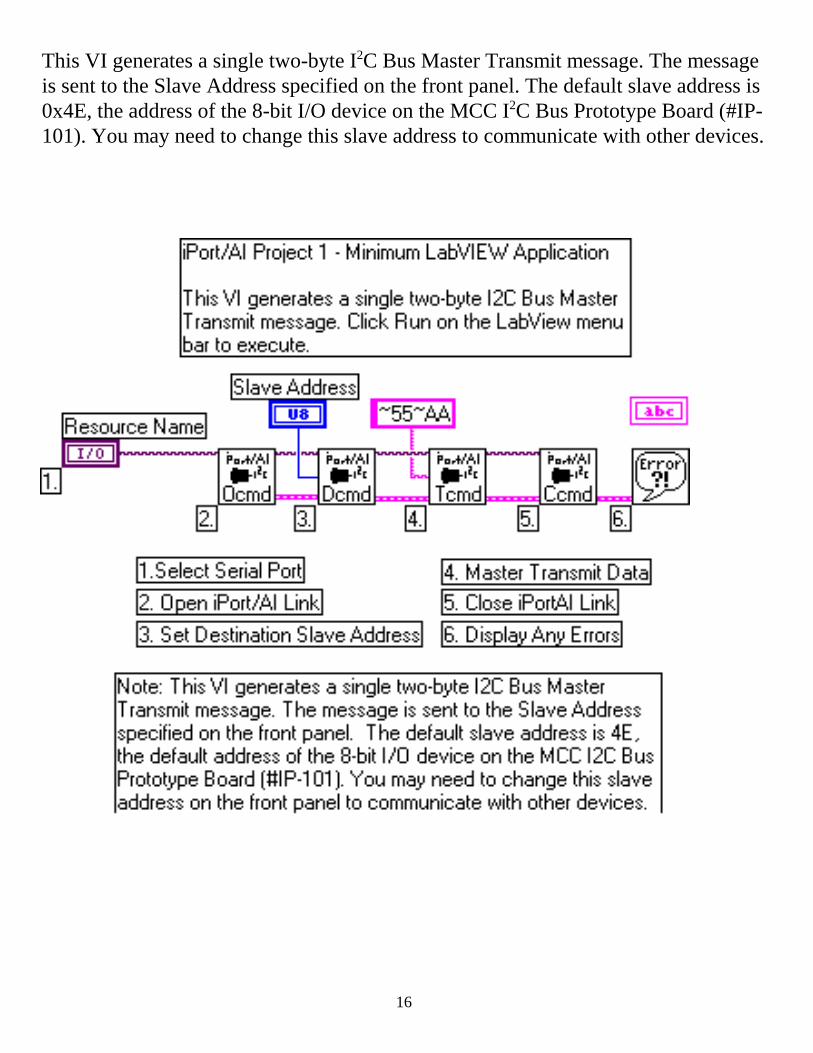
Project 1, A Minimum LabVIEW Application
Project 1, like the previous quick example, also operates in open-loop mode. Buthere we have added the ability to change the I2C Bus destination slave address to thefront panel.
16
This VI generates a single two-byte I2C Bus Master Transmit message. The messageis sent to the Slave Address specified on the front panel. The default slave address is0x4E, the address of the 8-bit I/O device on the MCC I2C Bus Prototype Board (#IP-101). You may need to change this slave address to communicate with other devices.

17
Front Panel
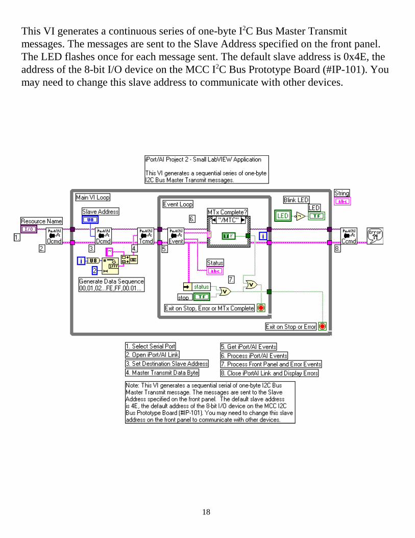
Project 2, A Small LabVIEW Application
Unlike the previous example, this example operates in closed-loop mode. Here, oncethe Master Transmit command is sent to the iPort/AI, the application enters an EventLoop that monitors and processes responses from the iPort/AI Adapter.
The Event Loop calls the iPort/AI Event Handler VI. This VI monitors the RS-232communications port for messages from the iPort/AI host adapter, and returns anEvent Code string that can be used to control a LabVIEW case structure, and anEvent String that includes the Event Code string plus any data received by the hostadapter.
The Event Loop also includes a case structure. This case structure has a diagram foreach iPort/AI Event Code string, and takes appropriate actions when Event Codesare received.
18
This VI generates a continuous series of one-byte I2C Bus Master Transmitmessages. The messages are sent to the Slave Address specified on the front panel.The LED flashes once for each message sent. The default slave address is 0x4E, theaddress of the 8-bit I/O device on the MCC I2C Bus Prototype Board (#IP-101). Youmay need to change this slave address to communicate with other devices.

19
Front Panel
Project 3, A Different Way
This project is similar to Project 2 above, but uses separate while loops to processMaster Transmit and iPort/AI response events.

20
This VI generates a continuous series of one-byte I2C Bus Master Transmitmessages. The messages are sent to the Slave Address specified on the front panel.The LED flashes once for each message sent. This project is similar to Project 2, butit uses a separate parallel loop to process iPort/AI events. The default slave addressis 0x4E, the address of the 8-bit I/O device on the MCC I2C Bus Prototype Board(#IP-101). You may need to change this slave address to communicate with otherdevices.

21
Message Manager Front Panel
LabVIEW Message Manager Project
iPort/AI Message Manager VI is a full-featured LabVIEW VI that supports all fourI2C Bus message modes, including:
1. Master Transmit 2. Master Receive 3. Slave Transmit 4. Slave Receive
Also support are other I2C Bus features, including:
1. General Call 2. Master Transmit/Receive

22
Mes
sage
Man
ager
Blo
ck D
iagr
am
As s
how
n in
it’s
blo
ck d
iagr
am, t
he M
essa
ge M
anag
er V
I firs
t exe
cute
s a st
art-u
p se
quen
ce, t
hen
ente
rs it
sm
ain
loop
. The
mai
n lo
op c
onsi
sts o
f a F
ront
Pan
el H
andl
er, a
nd a
n iP
ort/A
I Eve
nt H
andl
er.
The
Fron
t Pan
el H
andl
er d
etec
ts a
nd p
roce
sses
ope
rato
r int
erac
tions
with
the
fron
t pan
el.
The
iPor
t/AI E
vent
Han
dler
det
ects
and
pro
cess
es re
spon
ses f
rom
the
iPor
t/AI h
ost a
dapt
er.
23
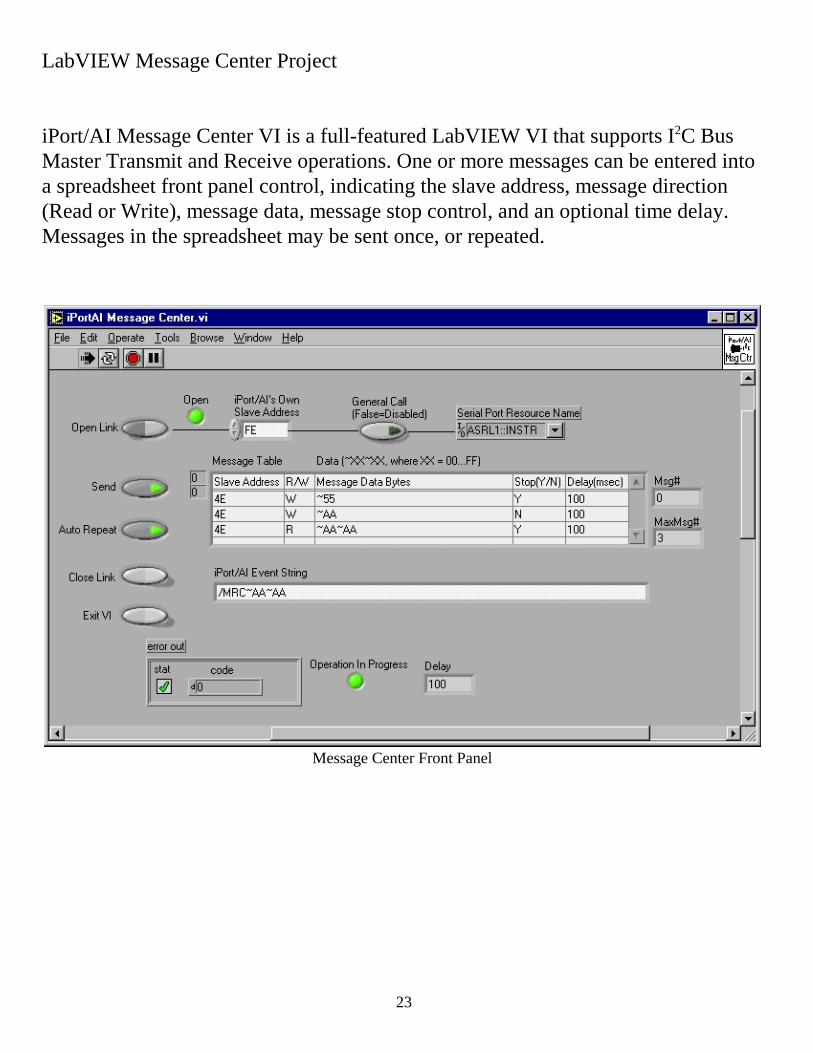
Message Center Front Panel
LabVIEW Message Center Project
iPort/AI Message Center VI is a full-featured LabVIEW VI that supports I2C BusMaster Transmit and Receive operations. One or more messages can be entered intoa spreadsheet front panel control, indicating the slave address, message direction(Read or Write), message data, message stop control, and an optional time delay.Messages in the spreadsheet may be sent once, or repeated.

24
Mes
sage
Cen
ter B
lock
Dia
gram
The
Mes
sage
Cen
ter V
I is s
imila
r to
the
prev
ious
Mes
sage
Man
ager
VI,
exce
pt th
e Fr
ont-P
anel
Han
dler
has
bee
n re
plac
ed w
ith a
Mes
sage
Tab
le P
roce
ssor
.
The
Mes
sage
Tab
le P
roce
ssor
han
dles
ope
rato
r int
erac
tions
with
the
fron
t pan
el, a
nd se
quen
ces
thro
ugh
a se
ries o
f mes
sage
s to
be se
nt a
cros
s the
I2 C B
us.

25
Part 4
LabVIEW iPort/AILibrary Reference

26
This section provides a description of the LabVIEW iPort/AI library command VI’s.
LabVIEW iPort/AI Library VI’s
Command Description
Close I2C Connection (Ccmd) VICauses the adapter to disconnect from the I2C Bus.
Set Destination Slave Address (Dcmd) VISets the I2C Bus destination slave address forsubsequent Master Transmit or Master Receivemessages sent by the adapter.
General Call Enable (Gcmd) VIEnables or disables the adapter's addressed slaveresponse to the General Call (0x00) address.
Hex Only Display (Hcmd) VIControls how the adapter will send master or slavereceive message data to its host computer.
Set Own Slave Address (Icmd) VISets the adapter's own slave address.
Byte Array to Hex-equivalent String.viConvert a single-dimension byte array into acompatible Hex-equivalent string.

27
EventHandler V01.10 VIMonitors the host adapter serial link for responses.
String To Byte Array.viConvert a Hex-equivalent string into a one-dimensional byte array.
Open Connection (Ocmd) VIEstablishes the link between the host computer andthe adapter.
Master Read Message (Rcmd) VIRead the specified number of data bytes from thecurrently selected Destination slave address.
Reset VICauses the adapter to re-boot and revert to its defaultstate.
Slave Transmit Message (Scmd) VICauses the adapter to write specific data bytes to therequesting I2C Bus Master Receiver device.
Master Transmit Message (Tcmd) VIWrite the specified data bytes to the currentlyselected Destination slave address.

28
Connector Pane
LabVIEW iPort/AI Library ReferenceClose I2C Connection (Ccmd) VIThe I2C Connection (Ccmd) VI sends a /C command to the host adapter and closesthe RS-232 serial communication link. A /C command causes the adapter todisconnect from the I2C Bus. The adapter’s normal response to the /C command is"/CCC", Close Connection Complete.
VISA resource name specifies the resource that will be opened. Thiscontrol also specifies the session and class. Refer to VISA ResourceName Control for more information.
Error In describes error conditions that occur before this VI runs. Thedefault input of this cluster is no error. If an error already occurred, thisVI returns the value of error in error out. The VI runs normally only if noincoming error exists. Otherwise, the VI passes the error in value to errorout. The error in cluster contains the following parameters.
Error Out contains error information. If error in indicates an error, errorout contains the same error information. Otherwise, it describes the errorstatus that this VI produces.

29
Connector Pane
Set Destination Slave Address (Dcmd) VIThe Set Destination Slave Address (Dcmd) VI sends a /D command to the iPort/AIhost adapter. The /D command sets the I2C Bus destination slave address forsubsequent Master Transmit or Master Receive messages sent by the iPort/AI. The/D command accepts even numbered slave addresses in the range of 0x00 to 0xFE.The selected slave address remains in effect until changed by another /D command,or the adapter is reset. The default slave address is 0x00. The adapter’s normalresponse to the /D command is "*", which is translated by the adapter’s Event VI to"/RDY".
VISA resource name specifies the resource that will be opened. Thiscontrol also specifies the session and class. Refer to VISA ResourceName Control for more information.Destination Slave Address specifies the slave address for subsequentMaster Transmit or Master Receive messages sent by the adapter. Slaveaddresses may be even numbered in the range of 0x00 to 0xFE.error IO describes error conditions that occur before this VI runs. Thedefault input of this cluster is no error. If an error already occurred, thisVI returns the value of error in error out. The VI runs normally only if noincoming error exists. Otherwise, the VI passes the error in value to errorout. The error in cluster contains the following parameters.Duplicate VISA Resource Name is a copy of the VISA resource namethat is passed out of the VISA functions. Refer to VISA Resource NameControl for more information.error out contains error information. If error in indicates an error, errorout contains the same error information. Otherwise, it describes the errorstatus that this VI produces.

30
Connector Pane
General Call Enable (Gcmd) VIThe Call Enable (Gcmd) VI sends a /G command to the host adapter. The /Gcommand enables or disables the adapter's addressed slave response to the generalcall (0x00) address. The adapter’s normal response is "*", which is translated by theEvent VI to "/RDY".
VISA resource name specifies the resource that will be opened. Thiscontrol also specifies the session and class. Refer to VISA Resource NameControl for more information.
General Call enable specifies that the adapter will respond to the I2C BusGeneral Call address (0x00).
Error In describes error conditions that occur before this VI runs. Thedefault input of this cluster is no error. If an error already occurred, this VIreturns the value of error in error out. The VI runs normally only if noincoming error exists. Otherwise, the VI passes the error in value to errorout. The error in cluster contains the following parameters.
Duplicate VISA Resource Name is a copy of the VISA resource namethat is passed out of the VISA functions. Refer to VISA Resource NameControl for more information.
Error Out contains error information. If error in indicates an error, errorout contains the same error information. Otherwise, it describes the errorstatus that this VI produces

31
Connector Pane
Hex Only Display (Hcmd) VIThe Hex Only Display (Hcmd) VI sends a /H command to the host adapter. The /Hcommand controls how the adapter will send master or slave receive message data toits host computer. When disabled, received I2C Bus message data bytes representingASCII printable characters are sent as their ASCII printable character. Non-ASCIIprintable data bytes are always sent in Hex (~00...~FF) form. When Hex OnlyDisplay enabled, all received message data is sent in Hex (~00...~FF) form. Theadapter’s normal response is "*", which is translated by the Event VI to "/RDY".
VISA resource name specifies the resource that will be opened. Thiscontrol also specifies the session and class. Refer to VISA Resource NameControl for more information.Hex Only Display controls the output of received message data in ASCIIprintable and Hex, or Hex only format.Error In describes error conditions that occur before this VI runs. Thedefault input of this cluster is no error. If an error already occurred, this VIreturns the value of error in error out. The VI runs normally only if noincoming error exists. Otherwise, the VI passes the error in value to errorout. The error in cluster contains the following parameters.
Duplicate VISA Resource Name is a copy of the VISA resource namethat is passed out of the VISA functions. Refer to VISA Resource NameControl for more information.Error Out contains error information. If error in indicates an error, errorout contains the same error information. Otherwise, it describes the errorstatus that this VI produces.

32
Connector Pane
Set iPort/AI's Own Slave Address (Icmd) VI
The Set Own Slave Address (Icmd) VI sends a /I command to the host adapter. The/I command sets the adapter's own slave address to the specified Slave Address. Theadapter responds to slave transmit and slave receive messages sent to this address.The adapter’s normal response to the /I command is "*", which is translated by theEvent VI to "/RDY".
VISA resource name specifies the resource that will be opened. Thiscontrol also specifies the session and class. Refer to VISA ResourceName Control for more information.iPort/AI's Slave Address specifies the slave address the adapter willrespond to in slave transmit and receive operations. The Slave Addressescan be an even numbered in the range of 0x02 to 0xFE.Error In describes error conditions that occur before this VI runs. Thedefault input of this cluster is no error. If an error already occurred, thisVI returns the value of error in error out. The VI runs normally only if noincoming error exists. Otherwise, the VI passes the error in value to errorout. The error in cluster contains the following parameters.Duplicate VISA Resource Name is a copy of the VISA resource namethat is passed out of the VISA functions. Refer to VISA Resource NameControl for more information.Error Out contains error information. If error in indicates an error, errorout contains the same error information. Otherwise, it describes the errorstatus that this VI produces.

33
Connector Pane
Byte Array to Hex-equivalent String.vi
The Byte Array to Hex-equivalent String VI is a helper VI. It can be used to converta single-dimension byte array into a compatible Hex-equivalent string. Hex-equivalent strings are used by Master Transmit, Master TxRx, and Slave TransmitVIs to represent one or more bytes (U8) of any value (00...FF hexadecimal or 0...255decimal) and still maintain the ASCII character interface with the adapter.
A Hex-equivalent string contains sets of three ASCII characters for each data byte.This three ASCII character set uses the form "~xx", where the "~" character is aHex-equivalent marker, and the "xx" represents a string of two ASCII-Hexadecimalcharacters that represent an 8-bit unsigned number in the range of 00 to FFhexadecimal.
Byte Array In a single-dimension byte array to be converted to anadapter compatible Hex-equivalent string.iPort/AI HexEquivalent String Out contains a compatible Hex-equivalent string. Hex-equivalent strings are used by Master Transmit,Master TxRx, and Slave Transmit VIs to represent one or more bytes(U8) of any value (00...FF hexadecimal or 0...255 decimal) and stillmaintain the ASCII character interface with the adapter.
A Hex-equivalent string contains sets of three ASCII characters for eachdata byte. This three ASCII character set uses the form "~xx", where the"~" character is a Hex-equivalent marker, and the "xx" represents a stringof two ASCII-Hexadecimal characters that represent an 8-bit unsignednumber in the range of 00 to FF hexadecimal.

34
Connector Pane
EventHandler V01.10 VI
The Event Handler VI monitors the host adapter serial link for responses. With eachEvent Handler call, any available receive characters are assembled into a string untilthe input stream is exhausted, or a terminating character (CR, or *) is received and aminimum (4 character) response is present. The Event String Out may contain:
a. The complete response string received from the adapter.
b. An "/NDA" if no input stream data is available.
c. A null string ("") if no complete response is present.
d. An Event Handler error string .
The Event Code Out contains the first 4 characters on the Event String, and can beused as input to a case structure to identify the specific adapter event.
VISA resource name specifies the resource that will be opened. Thiscontrol also specifies the session and class. Refer to VISA ResourceName Control for more information.
Error In describes error conditions that occur before this VI runs. Thedefault input of this cluster is no error. If an error already occurred, thisVI returns the value of error in error out. The VI runs normally only if noincoming error exists. Otherwise, the VI passes the error in value to errorout. The error in cluster contains the following parameters.

35
Event Code Out is a null string, or a 4 character string representing anhandler event. An "/NDA" indicates no data is available in the serial portinput stream. A null string indicates the handler is processing a response,but the response is not complete. Other strings include event handlererrors, adapter response codes, or "/RDY" which the event handlergenerates when it receives "*" ready response. This string is suitable forinput to a LabVIEW case structure.
Event String Out contains the complete adapter response string. For aMaster Read operation, this string contains "/MRCxxx". For a SlaveReceive operation, this string contains "/SRCxxx" standard slaveaddressing, or "/GRCxxx" for general call slave addressing. In all threecases, "xxx" represents printable ASCII or Hex-equivalent (~00...~FF)data bytes.
Duplicate VISA Resource Name is a copy of the VISA resource namethat is passed out of the VISA functions. Refer to VISA Resource NameControl for more information.

36
Connector Pane
Hex-equivalent String To Byte Array.vi
The Hex-equivalent String to Byte Array VI is a helper VI. It can be used to converta Hex-equivalent string into a one-dimensional byte array ready for additionalprocessing. Hex-equivalent strings are return by the Event Handler VI in response toMaster Receive, Master TxRx, and Slave Receive messages. A Hex-equivalentstring represent one or more bytes (U8) of any value (00...FF hexadecimal or 0...255decimal) and still maintain the ASCII character interface with the adapter.
To assist in processing the Event String Out terminal on the Event Handler VI, theHex-equivalent String to Byte Array VI provides a default offset of 4 to step past theleading four character Event Code present in the Event String Out.
A Hex-equivalent string contains sets of three ASCII characters for each data byte.This three ASCII character set uses the form "~xx", where the "~" character is aHex-equivalent marker, and the "xx" represents a string of two ASCII-Hexadecimalcharacters that represent an 8-bit unsigned number in the range of 00 to FFhexadecimal.
Offset (4) to the first Hex-equivalent string set. The default value (4)steps past the leading four character Event Code present in the EventString Out.HexEquivalent String Out contains a compatible Hex-equivalent stringto be converted to a single-dimension byte array. Hex-equivalent stringsare used in the Event String Out connector of Master Receive Complete(/MRC), Slave Receive Complete (/SRC) and General Call Receive(/GRC) Events to represent one or more bytes (U8) of any value (00...FFhexadecimal or 0...255 decimal) and still maintain the ASCII characterinterface with the adapter.
A Hex-equivalent string contains sets of three ASCII characters for each

37
data byte. This three ASCII character set uses the form "~xx", where the"~" character is a Hex-equivalent marker, and the "xx" represents a stringof two ASCII-Hexadecimal characters that represent an 8-bit unsignednumber in the range of 00 to FF hexadecimal.Byte Array In a single-dimension byte array representing the data in acompatible Hex-equivalent string.

38
Connector Pane
Open Connection (Ocmd) VI
The Open Connection (Ocmd) VI establishes the link between the host computer andthe adapter. The following steps are performed: 1. Sets serial port communication parameters. 2. Issues an adapter Reset command. 3. Initializes the adapter's own slave address and general call (address 0x00) enable. 4. Sends a /O command to the host adapter. The /O command activates the adapter as an active master or slave device on the I2CBus. The normal response to the /O command is "*", which is translated by theEvent VI to "/RDY".
VISA resource name specifies the resource that will be opened. Thiscontrol also specifies the session and class. Refer to VISA ResourceName Control for more information.iPort/AI's Slave Address specifies the slave address the adapter willrespond to in slave transmit and receive operations. The Slave Addressescan be an even numbered in the range of 0x02 to 0xFE.High Baud Rate enables 115,000 baud communication. Available onlyfor adapters supporting this rate.General Call enable specifies that the adapter will respond to the I2CBus General Call address (0x00).Error In describes error conditions that occur before this VI runs. Thedefault input of this cluster is no error. If an error already occurred, thisVI returns the value of error in error out. The VI runs normally only if noincoming error exists. Otherwise, the VI passes the error in value to error

39
out. The error in cluster contains the following parameters.Duplicate VISA Resource Name is a copy of the VISA resource namethat is passed out of the VISA functions. Refer to VISA Resource NameControl for more information.Error Out contains error information. If error in indicates an error, errorout contains the same error information. Otherwise, it describes the errorstatus that this VI produces.

40
Connector Pane
Master Read Message (Rcmd) VIThe Master Read Message (Rcmd) VI sends a /R command to the host adapter. The/R command causes the adapter to read the specified number of data bytes from thecurrently selected Destination slave address, with or without generating a messageterminating I2C Bus Stop. The Destination slave address is the address specified by the last Set DestinationSlave Address command received by the adapter. The specified number on bytes to read can be in the range of 0 to 32767, with a bytecount of zero indicating a Variable Length message read, where the first bytereceived from the slave device indicates the number of additional trailing bytes toread. The adapter automatically reads the first byte and all additional bytes from theslave. The normal response to the /R command is "/MRC" followed by the data read fromthe slave. All message bytes, including the Length byte are included in the response.Other possible responses are possible depending on the adapter status and I2C Busactivity. See the Event VI, and the adapter’s User's Guide, for a complete list ofresponses. Received text is a representation of the data of the data bytes within the MasterReceive message. The format of this data is controlled by the current value of theHex Only Display setting.
VISA resource name specifies the resource that will be opened. Thiscontrol also specifies the session and class. Refer to VISA ResourceName Control for more information.Bytes To Read specifies the number on bytes to read. This can be in therange of 0 to 32767, with a byte count of zero indicating a VariableLength message read, where the first byte received from the slave deviceindicates the number of additional trailing bytes to read. The adapter

41
automatically reads the first byte and all additional bytes from the slave.doStop specifies if the adapter should generate a message terminatingI2C Bus Stop. Error In describes error conditions that occur before this VI runs. Thedefault input of this cluster is no error. If an error already occurred, thisVI returns the value of error in error out. The VI runs normally only if noincoming error exists. Otherwise, the VI passes the error in value to errorout. The error in cluster contains the following parameters.Duplicate VISA Resource Name is a copy of the VISA resource namethat is passed out of the VISA functions. Refer to VISA Resource NameControl for more information.Error Out contains error information. If error in indicates an error, errorout contains the same error information. Otherwise, it describes the errorstatus that this VI produces.

42
Connector Pane
Reset VI
The VI sends a reset sequence (Ctrl/R, Ctrl/R, Ctrl/R) to the host adapter. A resetsequence causes the adapter to re-boot and revert to its default state. The normalresponse is "*", which is translated by the Event VI to "/RDY".
VISA resource name specifies the resource that will be opened. Thiscontrol also specifies the session and class. Refer to VISA ResourceName Control for more information.
Error In describes error conditions that occur before this VI runs. Thedefault input of this cluster is no error. If an error already occurred, thisVI returns the value of error in error out. The VI runs normally only if noincoming error exists. Otherwise, the VI passes the error in value to errorout. The error in cluster contains the following parameters.
Duplicate VISA Resource Name is a copy of the VISA resource namethat is passed out of the VISA functions. Refer to VISA Resource NameControl for more information.
Error Out contains error information. If error in indicates an error, errorout contains the same error information. Otherwise, it describes the errorstatus that this VI produces.

43
Connector Pane
Slave Transmit Message (Scmd) VI
The Slave Transmit Message (Scmd) VI sends a /S command to the host adapter.The /S command should be issued to the adapter in response to a Slave TransmitRequest "/STR". The /S command causes the adapter to write the specified databytes to the requesting I2C Bus Master Receiver device.
NOTE: Upon receiving a Slave Transmit request from a Master Receiver device onthe I2C Bus, the adapter outputs a Slave Transmit Request "/STR" to its hostcomputer, and initiates an I2C Bus Clock Stretch (SCL line Low) until a /S commandis received from the host. While clock stretching, no other messages can betransmitted on the I2C Bus.
The Slave Transmit Message VI accepts one or more printable ASCII or Hex-equivalent (~00...~FF) data bytes. The special characters tilde (~) and CarriageReturn (CR) have special meaning to the adapter and must be sent in their Hex-equivalent form (~ = ~7E, CR = ~0D).
The normal response to the /S command is Slave Transmit Complete "/STC",although other responses are possible depending on adapter’s status and I2C Busactivity. See the Event VI, and the adapter’s User's Guide, for a complete list ofresponses.
VISA resource name specifies the resource that will be opened. Thiscontrol also specifies the session and class. Refer to VISA ResourceName Control for more information.I2C Message String specifies the message data the adapter transmits tothe requesting I2C Bus Master Receiver device. The Slave Transmit

44
Message VI accepts one or more printable ASCII or Hex-equivalent(~00...~FF) data bytes. The special characters tilde (~) and CarriageReturn (CR) have special meaning to the adapter and must be sent intheir Hex-equivalent form (~ = ~7E, CR = ~0D). Example: To send thethree bytes 00,01, and 02, the message string should be "~00~01~02".Error In describes error conditions that occur before this VI runs. Thedefault input of this cluster is no error. If an error already occurred, thisVI returns the value of error in error out. The VI runs normally only if noincoming error exists. Otherwise, the VI passes the error in value to errorout. The error in cluster contains the following parameters.Duplicate VISA Resource Name is a copy of the VISA resource namethat is passed out of the VISA functions. Refer to VISA Resource NameControl for more information.Error Out contains error information. If error in indicates an error, errorout contains the same error information. Otherwise, it describes the errorstatus that this VI produces.

45
Connector Pane
Master Transmit Message (Tcmd) VI
The iPort/AI Master Transmit Message (Tcmd) VI sends a /T command to theiPort/AI host adapter. The /T command causes the iPort/AI to write the specifieddata bytes to the currently selected Destination slave address, with or withoutgenerating a message terminating I2C Bus Stop.
The Destination slave address is the address specified by the last Set DestinationSlave Address command received by the iPort/AI.
The Master Transmit Message VI accepts zero or more printable ASCII or Hex-equivalent (~00...~FF) data bytes. The special characters tilde (~) and CarriageReturn (CR) have special meaning to the iPort/AI and must be sent in their Hex-equivalent form (~ = ~7E, CR = ~0D).
The iPort/AI normal response to the /T command is "/MTC", although otherresponses are possible depending on iPort/AI status and I2C Bus activity. See theiPort/AI Event VI, and the iPort/AI User's Guide, for a complete list of responses.
VISA resource name specifies the resource that will be opened. Thiscontrol also specifies the session and class. Refer to VISA ResourceName Control for more information.I2C Message String specifies the message data the iPort/AI transmit tothe currently selected slave address. The Master Transmit Message VI accepts zero or more printable ASCIIor Hex-equivalent (~00...~FF) data bytes. The special characters tilde (~)and Carriage Return (CR) have special meaning to the iPort/AI and mustbe sent in their Hex-equivalent form (~ = ~7E, CR = ~0D). Example: Tosend the three bytes 00,01, and 02, the message string should be

46
"~00~01~02".doStop specifies if the iPort/AI should generate a message terminatingI2C Bus Stop. Error In describes error conditions that occur before this VI runs. Thedefault input of this cluster is no error. If an error already occurred, thisVI returns the value of error in error out. The VI runs normally only if noincoming error exists. Otherwise, the VI passes the error in value to errorout. The error in cluster contains the following parameters.Duplicate VISA Resource Name is a copy of the VISA resource namethat is passed out of the VISA functions. Refer to VISA Resource NameControl for more information.Error Out contains error information. If error in indicates an error, errorout contains the same error information. Otherwise, it describes the errorstatus that this VI produces.

47
Micro Computer Control (MCC)
Developer License Agreement
**** NOTICE TO USER: THIS IS A CONTRACT. BY INSTALLING THISSOFTWARE YOU ACCEPT ALL THE TERMS AND CONDITIONS OFTHIS AGREEMENT.****
This Developer License Agreement accompanies an MCC Software product andrelated explanatory materials ("Software"). The term "Software" also shall includeany upgrades, modified versions or updates of the Software licensed to you byMCC.
Please read this Agreement carefully.
Upon your acceptance of this Agreement, MCC grants to you a nonexclusive licenseto use the Software, provided that you agree to the following:
1. Use of the Software.
You may install the Software on a hard disk or other storage device; install and usethe Software on a file server for use on a network for the purposes of (i) permanentinstallation onto hard disks or other storage devices or (ii) use of the Software oversuch network; and make backup copies of the Software.
2. Distribution of Software.
You may make and distribute unlimited copies of the Software, including copies forcommercial distribution, as long as:
a. The Software is not the sole or major component of the distribution.
b. Each copy that you make and distribute contains this Agreement.
c. Each copy that you make and distribute contains the same copyright and other

48
proprietary notices pertaining to this Software that appear in the Software.
If you download the Software from the Internet or similar on-line source, you mustinclude the MCC copyright notice for the Software with any on-line distribution andon any media you distribute that includes the Software.
3. Ownership of Software.
This Software is owned by MCC or its suppliers and is protected by copyright lawand international copyright treaty. Therefore, you must treat this Software like anyother copyrighted material (e.g., a book), except that you may make and distributecopies of the Software as defined in "Distribution of Software", above.
4. Export Restrictions
This Software is subject to U.S. Commerce Department export restrictions, and isintended for use in the country into which MCC distributed it (or in the EEC, ifdistributed into the EEC).
5. Termination
Violation of any of the above provisions automatically terminates this license. Upontermination of this license, you agree to stop any distribution of the Software, anddestroy all copies of the Software in your possession.
Life Support Applications
MCC Products are not designed for use in life support appliances, devices, orsystems where the malfunction of a MCC Product can reasonably be expected toresult in a personal injury.
High Risk Activities
The Software is not fault-tolerant and is not designed, manufactured or intended foruse or resale as on-line control equipment in hazardous environments requiring

49
fail-safe performance, such as in the operation of nuclear facilities, aircraftnavigation or communication systems, air traffic control, direct life supportmachines, or weapons systems, in which the failure of the Software could leaddirectly to death, personal injury, or severe physical or environmental damage("High Risk Activities"). MCC and its suppliers specifically disclaim any express orimplied warranty of fitness for High Risk Activities.
Limited Warranty
MCC warrants, as the sole warranty, that any disks on which the Software isfurnished will be free of defects in materials and workmanship under normal use andconditions for a period of thirty (30) days from the date received. No distributor,dealer, or any other entity or person is authorized to expand or alter this Agreement. MCC does not warrant that the functions contained in the Software will beuninterrupted or error-free. Except as stated above in this paragraph, the Software isprovided as is without warranty of any kind either expressed or implied, included butnot limited to the implied warranties of merchantability and fitness for a particularpurpose. You assume entire risk as it applies to the quality and performance of theSoftware. Should the Software prove defective, the Purchaser (and not MCC,authorized MCC distributors, or dealers) assume the entire cost of all necessaryservicing, repair or correction.
Limitation of Remedies and Damages
MCC's entire liability and remedy will be the replacement of any disks not meetingMCC "Limited Warranty" explained above.
In no event will MCC be liable for any damages direct, indirect, incidental, orconsequential, including damages for lost profits, lost savings, or other incidental orconsequential damage arising out of the use or inability to use such Software, even ifMCC has been advised of the possibility of such damages or for any claim by anyother party. In no event will MCC's liability of damages to the you or any otherperson ever exceed the amount of the license fee you paid to use the Software

50
regardless of the form of the claim.
U.S. GOVERNMENT RESTRICTED RIGHTSThe Software and documentation are provided with RESTRICTED RIGHTS. Use,duplication, or disclosure by the Government is subject to restrictions as set forth insubparagraphs(c)(1)(ii) of the Rights in Technical Data and Computer Softwareclause at DFARS 252.227-7013 or subparagraphs(c)(1) and (2) of the CommercialComputer Software-Restricted Rights at 48 CFR 52.227-19, as applicable.Manufacturer is Micro Computer Control Corporation, 17 ModelAvenue, Hopewell, New Jersey 08525.
GENERAL PROVISIONSThis license may only be modified in writing signed by you and an authorizedofficer of MCC. If any provision of this statement is found void or unenforceable,the remainder will remain valid and enforceable according to its terms. If anyremedy provided is determined to have failed for its essential purpose, all limitationsof liability and exclusions of damages set forth in the Limited Warranty shall remainin effect.
This Agreement is governed by the laws of the State of New Jersey USA (exceptUSA federal law governs copyrights and registered trademarks.) If an provision ofthis Agreement is deemed invalid by any court having jurisdiction, that particularprovision will be deemed deleted and will not affect the validity of any otherprovision of this Agreement. MCC reserves all rights not specifically granted in thisstatement.