Embed Size (px)
Citation preview
®
LabVIEW Driver For NORMA 4000/5000 Power Analyzer
Reference Manual
June 2007 © 2007 Fluke Corporation, All rights reserved. All product names are trademarks of their respective companies.

LIMITED WARRANTY AND LIMITATION OF LIABILITY BY USING THIS SOFTWARE PRODUCT IN ANY MANNER, YOU ARE AGREEING TO ACCEPT THE FOLLOWING TERMS AND CONDITIONS.
Fluke Corporation (Fluke) grants you a non-exclusive right to use Fluke NORMA View software (Product) on a single PC or on multiple PCs. This grant of license does not include the right to copy, modify, rent, lease, sell, transfer or distribute the Product or any portion thereof. You may not reverse engineer, decompile, or disassemble the Product.
Fluke warrants that the Product will perform in its intended environment substantially in accordance with the accompanying written materials for a period of 90 days from the date of license acceptance. Fluke does not warrant any downloading errors or that the Product will be error free or operate without interruption.
FLUKE DISCLAIMS ALL OTHER WARRANTIES, EITHER EXPRESS OR IMPLIED, BUT NOT LIMITED TO IMPLIED WARRANTIES OF MERCHANTABILITY AND FITNESS FOR A PARTICULAR PURPOSE, WITH RESPECT TO THE SOFTWARE AND THE ACCOMPANYING WRITTEN MATERIALS. In no event shall Fluke be liable for any damages whatsoever (including, without limitation, indirect, consequential, or incidental damages, damages for loss of business profits, business interruption, loss of business information, or other pecuniary loss) arising out of the use of or inability to use this Product, even if Fluke has been advised of the possibility of such damages.
Fluke Corporation P.O. Box 9090 Everett, WA 98206-9090 U.S.A.
Fluke Europe B.V. P.O. Box 1186 5602 BD Eindhoven The Netherlands
11/2001
To register your product online, visit register.fluke.com
i
Table of Contents
Title Page Introduction........................................................................................................ 1 Installation ......................................................................................................... 1 Common............................................................................................................. 1
LNOPA01 Getting Started ........................................................................ 1 LNOPA01 Three Phase Measurement Example ....................................... 2
LNOPA01 Initialize ........................................................................................... 2 LNOPA01 Initialize .................................................................................. 2 LNOPA01 Close ....................................................................................... 5
Connection ......................................................................................................... 6 LNOPA01 Connection .............................................................................. 6
Input ................................................................................................................... 7 LNOPA01 Configure Input....................................................................... 7 LNOPA01 Input Coupling ........................................................................ 8 LNOPA01 Input Shunt.............................................................................. 8 LNOPA01 Input Shunt Factor .................................................................. 9 LNOPA01 Input Filter State ..................................................................... 10 LNOPA01 Input Filter Low Pass Frequency ............................................ 10 LNOPA01 Number of Phases ................................................................... 10
Range ................................................................................................................. 11 LNOPA01 Configure Range ..................................................................... 11 LNOPA01 Range Auto ............................................................................. 12 LNOPA01 Range ...................................................................................... 13 LNOPA01 Range List ............................................................................... 13 LNOPA01 Scaling Factor ......................................................................... 14
Sync ................................................................................................................... 15 LNOPA01 Configure Sync ....................................................................... 15 LNOPA01 Configure Sync Source ........................................................... 15 LNOPA01 Sync State ............................................................................... 16 LNOPA01 Sync Source ............................................................................ 17 LNOPA01 Sync Source Auto ................................................................... 17 LNOPA01 Sync Level .............................................................................. 18 LNOPA01 Sync Level Auto ..................................................................... 18 LNOPA01 Sync Level Unit ...................................................................... 19 LNOPA01 Sync Slope .............................................................................. 19 LNOPA01 Sync LP Filter State ................................................................ 20

LabVIEW Driver Reference Manual
ii
LNOPA01 Sync LP Filter Frequency ....................................................... 20 LNOPA01 Sync Timeout .......................................................................... 20 LNOPA01 Sync Output State ................................................................... 21
Timebase............................................................................................................ 22 LNOPA01 Averaging Interval .................................................................. 22 LNOPA01 Sample Rate ............................................................................ 22 LNOPA01 Timer Reset............................................................................. 22 LNOPA01 Timer Reset Auto.................................................................... 22 LNOPA01 Query Timer Reset Time ........................................................ 23
Trigger ............................................................................................................... 23 LNOPA01 Configure Start Time Trigger ................................................. 23 LNOPA01 Configure Function Trigger .................................................... 23 LNOPA01 Initiate Continuous.................................................................. 29 LNOPA01 Trigger .................................................................................... 29 LNOPA01 Initiate Memory Trigger ......................................................... 30 LNOPA01 Trigger Source ........................................................................ 30 LNOPA01 Trigger Function ..................................................................... 31 LNOPA01 Trigger Time ........................................................................... 41 LNOPA01 Trigger Level .......................................................................... 42 LNOPA01 Trigger Slope .......................................................................... 43
Status.................................................................................................................. 43 LNOPA01 Averaging Status..................................................................... 43 LNOPA01 Wait For Operation Status Event ............................................ 44 LNOPA01 Status Registers....................................................................... 44 LNOPA01 Status Register Bit .................................................................. 45
Data Format ....................................................................................................... 46 LNOPA01 Data Format ............................................................................ 46 LNOPA01 Data Format Byte Order.......................................................... 47 LNOPA01 Format Transpose ................................................................... 47
Measurement Function ...................................................................................... 48 LNOPA01 Measurement Functions .......................................................... 48 LNOPA01 Functions All State.................................................................. 53 LNOPA01 Function Count ....................................................................... 54 LNOPA01 Concurrent Functions State..................................................... 54 LNOPA01 Harmonic Order ...................................................................... 54
Calculate Functions............................................................................................ 55 Integration...................................................................................................... 55
LNOPA01 Configure Integration.............................................................. 55 LNOPA01 Integration Functions .............................................................. 56 LNOPA01 Integration State ...................................................................... 57 LNOPA01 Integration Start Source .......................................................... 58 LNOPA01 Integration Start Time............................................................. 58 LNOPA01 Integration Stop Source........................................................... 59 LNOPA01 Integration Stop Time ............................................................. 59 LNOPA01 Integration Interval.................................................................. 60 LNOPA01 Start Integration Immediate .................................................... 60 LNOPA01 Stop Integration Immediate..................................................... 61 LNOPA01 Clear Integration Function ...................................................... 61 LNOPA01 Auto Clear State...................................................................... 61
Memory Record ................................................................................................. 62 LNOPA01 Configure Memory ................................................................. 62 LNOPA01 Record Length......................................................................... 68 LNOPA01 Max Record Length ................................................................ 69 LNOPA01 Pretrigger Length .................................................................... 69 LNOPA01 Total Scan Count .................................................................... 70
Contents (continued)
iii
LNOPA01 Pretrigger Scan Count ............................................................. 70 LNOPA01 Memory State.......................................................................... 70 LNOPA01 Memory Block Count ............................................................. 71 LNOPA01 Sample Factor ......................................................................... 71 LNOPA01 Memory Function List ............................................................ 72 LNOPA01 Delete Memory ....................................................................... 78
Spectrum ............................................................................................................ 78 LNOPA01 Configure Spectrum................................................................ 78 LNOPA01 Initiate Spectrum..................................................................... 79 LNOPA01 Spectrum Function List........................................................... 79 LNOPA01 Spectrum Mode....................................................................... 80 LNOPA01 Spectrum Start Frequency....................................................... 80 LNOPA01 Spectrum Stop Frequency ....................................................... 81
System................................................................................................................ 82 LNOPA01 System Time and Date ............................................................ 82 LNOPA01 System Key Lock.................................................................... 82 LNOPA01 System Version ....................................................................... 82 LNOPA01 System Baud Rate ................................................................... 83 LNOPA01 Display State ........................................................................... 83 LNOPA01 System Key ............................................................................. 83
Hardcopy............................................................................................................ 85 LNOPA01 Read Screen Data.................................................................... 85
Process Interface ................................................................................................ 85 Process Input ................................................................................................. 85
LNOPA01 Process Input Type.................................................................. 85 LNOPA01 Drive Type .............................................................................. 86 LNOPA01 Drive Pole Pair Count ............................................................. 86 LNOPA01 Process Power Reference........................................................ 87 LNOPA01 Configure Torque.................................................................... 88 LNOPA01 Torque Scale Factor ................................................................ 88 LNOPA01 Torque Offset .......................................................................... 89 LNOPA01 Torque Offset Immediate ........................................................ 90 LNOPA01 Configure Speed ..................................................................... 90 LNOPA01 Speed Scale Factor.................................................................. 91 LNOPA01 Speed Offset............................................................................ 92 LNOPA01 Speed Offset Immediate.......................................................... 93
Process Output............................................................................................... 93 LNOPA01 Configure Fixed Output .......................................................... 93 LNOPA01 Configure Variable Output ..................................................... 94 LNOPA01 Process Output Voltage........................................................... 99 LNOPA01 Process Output Mode.............................................................. 100 LNOPA01 Process Output Reference ....................................................... 101 LNOPA01 Process Output Gain ............................................................... 107 LNOPA01 Process Output Zero................................................................ 107
Measurement...................................................................................................... 108 LNOPA01 Query Measurements .............................................................. 108 LNOPA01 Query Measurements with Status Num .................................. 114 LNOPA01 Query Memory........................................................................ 120 LNOPA01 Fetch Memory Data Header.................................................... 120 LNOPA01 Fetch Memory......................................................................... 120 LNOPA01 Fetch Spectrum Data Header .................................................. 122 LNOPA01 Fetch Spectrum ....................................................................... 122 LNOPA01 Actual Memory Block Count.................................................. 123 LNOPA01 Free Memory........................................................................... 123 LNOPA01 Memory Abort ........................................................................ 123

LabVIEW Driver Reference Manual
iv
Utility ................................................................................................................. 123 LNOPA01 Self-Test.................................................................................. 123 LNOPA01 Error Message ......................................................................... 124 LNOPA01 Reset........................................................................................ 124 LNOPA01 Error Query ............................................................................. 124 LNOPA01 Revision Query ....................................................................... 125 LNOPA01 Error Query (Multiple)............................................................ 125 LNOPA01 Instrument Options ................................................................. 125 LNOPA01 Clear Status ............................................................................. 125 LNOPA01 Get Instrument Configuration ................................................. 125 LNOPA01 Write Instrument Configuration.............................................. 126 LNOPA01 Check Status ........................................................................... 126
1
Note This document is compliant with LNOPA01 LabVIEW Instrument Driver version 1.6.1.
Introduction This reference manual documents the instrument driver for the Fluke NORMA 4000/5000 Power Analyzer instruments. The driver contains VIs for opening, configuring, taking measurements from, and closing the instrument. For more information about how to work with instrument drivers in LabVIEW, please refer to your LabVIEW documentation.
Note This instrument driver is designed to work with LabVIEW 7.
Installation The driver files should be placed into your ...LabVIEW\INSTR.LIB\LNOPA01 directory.
Common
LNOPA01 Getting Started This VI is an application performing simple three phase measurement.
LabVIEW Driver Reference Manual
2
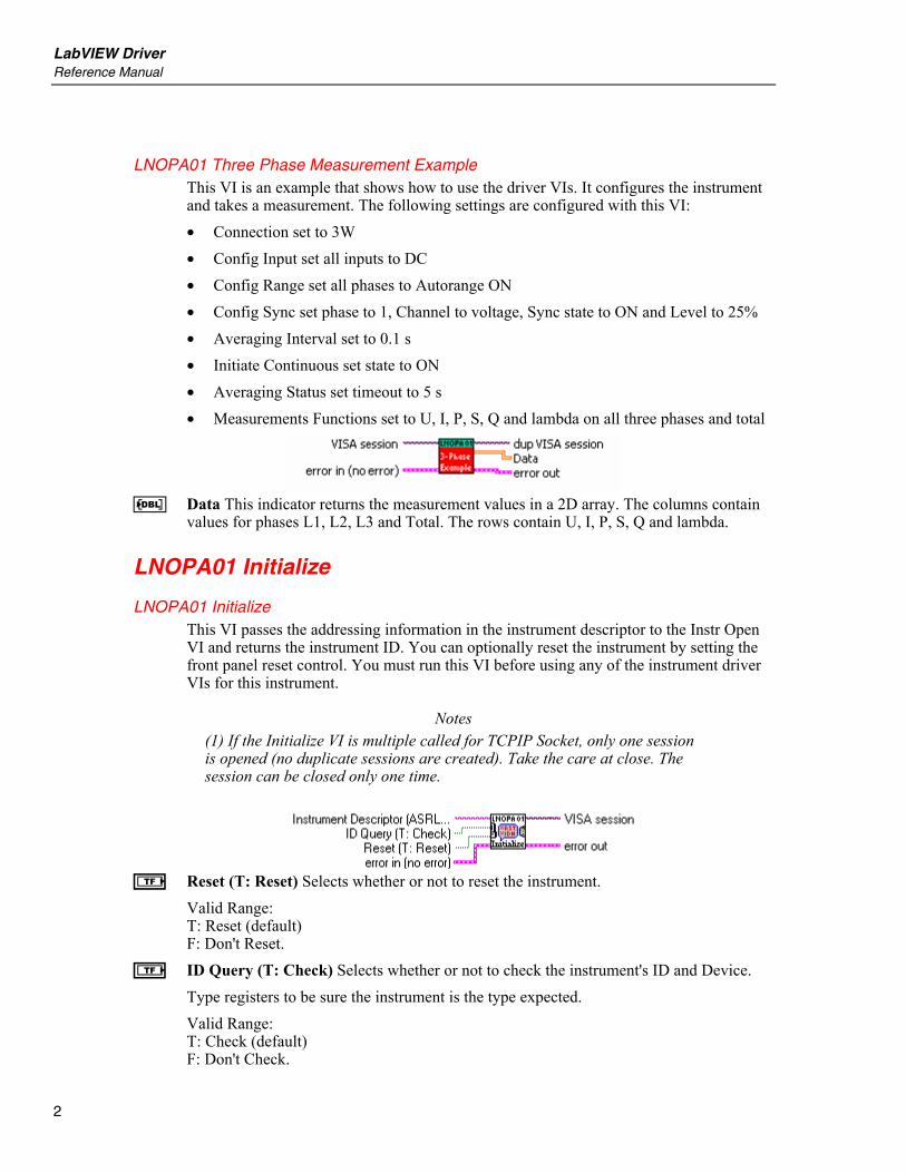
LNOPA01 Three Phase Measurement Example This VI is an example that shows how to use the driver VIs. It configures the instrument and takes a measurement. The following settings are configured with this VI: • Connection set to 3W • Config Input set all inputs to DC • Config Range set all phases to Autorange ON • Config Sync set phase to 1, Channel to voltage, Sync state to ON and Level to 25% • Averaging Interval set to 0.1 s • Initiate Continuous set state to ON • Averaging Status set timeout to 5 s • Measurements Functions set to U, I, P, S, Q and lambda on all three phases and total
G Data This indicator returns the measurement values in a 2D array. The columns contain
values for phases L1, L2, L3 and Total. The rows contain U, I, P, S, Q and lambda.
LNOPA01 Initialize
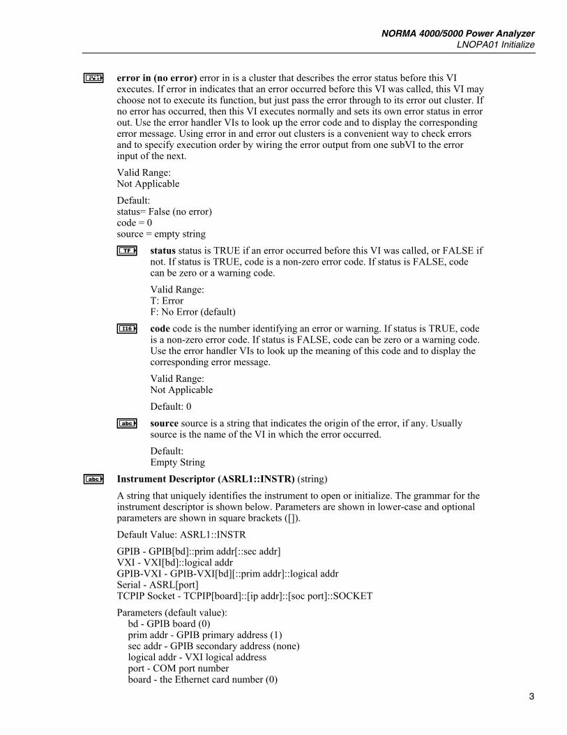
LNOPA01 Initialize This VI passes the addressing information in the instrument descriptor to the Instr Open VI and returns the instrument ID. You can optionally reset the instrument by setting the front panel reset control. You must run this VI before using any of the instrument driver VIs for this instrument.
Notes (1) If the Initialize VI is multiple called for TCPIP Socket, only one session is opened (no duplicate sessions are created). Take the care at close. The session can be closed only one time.
e Reset (T: Reset) Selects whether or not to reset the instrument.
Valid Range: T: Reset (default) F: Don't Reset.
e ID Query (T: Check) Selects whether or not to check the instrument's ID and Device. Type registers to be sure the instrument is the type expected. Valid Range: T: Check (default) F: Don't Check.
NORMA 4000/5000 Power Analyzer LNOPA01 Initialize
3
m error in (no error) error in is a cluster that describes the error status before this VI executes. If error in indicates that an error occurred before this VI was called, this VI may choose not to execute its function, but just pass the error through to its error out cluster. If no error has occurred, then this VI executes normally and sets its own error status in error out. Use the error handler VIs to look up the error code and to display the corresponding error message. Using error in and error out clusters is a convenient way to check errors and to specify execution order by wiring the error output from one subVI to the error input of the next. Valid Range: Not Applicable Default: status= False (no error) code = 0 source = empty string e status status is TRUE if an error occurred before this VI was called, or FALSE if
not. If status is TRUE, code is a non-zero error code. If status is FALSE, code can be zero or a warning code. Valid Range: T: Error F: No Error (default)
M code code is the number identifying an error or warning. If status is TRUE, code is a non-zero error code. If status is FALSE, code can be zero or a warning code. Use the error handler VIs to look up the meaning of this code and to display the corresponding error message. Valid Range: Not Applicable Default: 0
A source source is a string that indicates the origin of the error, if any. Usually source is the name of the VI in which the error occurred. Default: Empty String
A Instrument Descriptor (ASRL1::INSTR) (string) A string that uniquely identifies the instrument to open or initialize. The grammar for the instrument descriptor is shown below. Parameters are shown in lower-case and optional parameters are shown in square brackets ([]). Default Value: ASRL1::INSTR GPIB - GPIB[bd]::prim addr[::sec addr] VXI - VXI[bd]::logical addr GPIB-VXI - GPIB-VXI[bd][::prim addr]::logical addr Serial - ASRL[port] TCPIP Socket - TCPIP[board]::[ip addr]::[soc port]::SOCKET Parameters (default value):
bd - GPIB board (0) prim addr - GPIB primary address (1) sec addr - GPIB secondary address (none) logical addr - VXI logical address port - COM port number board - the Ethernet card number (0)

LabVIEW Driver Reference Manual
4
ip addr - ip address soc port - the socket port number
EXAMPLES: A GPIB instrument on GPIB board 0, at primary address 5, and no secondary addressing.
GPIB::5 A RS-232 instrument on COM port 1.
ASRL1 A TCPIP instrument on the LAN (one ethernet card number in the PC). The instrument IP address is 192.168.2.250, SOCKET is 23 (default value).
TCPIP0::192.168.2.250::23::SOCKET n error out error out is a cluster that describes the error status after this VI executes. If an
error occurred before this VI was called, error out is the same as error in. Otherwise, error out shows the error, if any, that occurred in this VI. Use the error handler VIs to look up the error code and to display the corresponding error message. Using error in and error out clusters is a convenient way to check errors and to specify execution order by wiring the error output from one subVI to the error input of the next. Valid Range: Not Applicable Default: status= False (no error) code = 0 source = empty string
f status status is TRUE if an error occurred, or FALSE if not. If status is TRUE, code is a non-zero error code. If status is FALSE, code can be zero or a warning code. Valid Range: T: Error F: No Error (default)
J code code is the number identifying an error or warning. If status is TRUE, code is a non-zero error code. If status is FALSE, code can be zero or a warning code. Use the error handler VIs to look up the meaning of this code and to display the corresponding error message. Valid Range: Not Applicable Default: 0
B source source is a string that indicates the origin of the error, if any. Usually source is the name of the VI in which the error occurred. Default: Empty String
j VISA session A unique reference to an instrument I/O session. It identifies which device to communicate with and all configuration information to perform the I/O. See the initialize VI for more information. Valid Range: Not Applicable
NORMA 4000/5000 Power Analyzer LNOPA01 Initialize
5
Default: Not Applicable
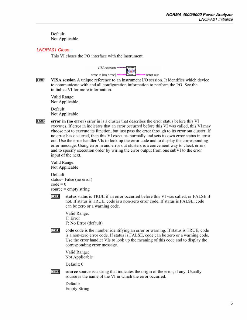
LNOPA01 Close This VI closes the I/O interface with the instrument.
i VISA session A unique reference to an instrument I/O session. It identifies which device
to communicate with and all configuration information to perform the I/O. See the initialize VI for more information. Valid Range: Not Applicable
Default: Not Applicable
m error in (no error) error in is a cluster that describes the error status before this VI executes. If error in indicates that an error occurred before this VI was called, this VI may choose not to execute its function, but just pass the error through to its error out cluster. If no error has occurred, then this VI executes normally and sets its own error status in error out. Use the error handler VIs to look up the error code and to display the corresponding error message. Using error in and error out clusters is a convenient way to check errors and to specify execution order by wiring the error output from one subVI to the error input of the next. Valid Range: Not Applicable Default: status= False (no error) code = 0 source = empty string e status status is TRUE if an error occurred before this VI was called, or FALSE if
not. If status is TRUE, code is a non-zero error code. If status is FALSE, code can be zero or a warning code. Valid Range: T: Error F: No Error (default)
I code code is the number identifying an error or warning. If status is TRUE, code is a non-zero error code. If status is FALSE, code can be zero or a warning code. Use the error handler VIs to look up the meaning of this code and to display the corresponding error message. Valid Range: Not Applicable Default: 0
A source source is a string that indicates the origin of the error, if any. Usually source is the name of the VI in which the error occurred. Default: Empty String

LabVIEW Driver Reference Manual
6
n error out error out is a cluster that describes the error status after this VI executes. If an error occurred before this VI was called, error out is the same as error in. Otherwise, error out shows the error, if any, that occurred in this VI. Use the error handler VIs to look up the error code and to display the corresponding error message. Using error in and error out clusters is a convenient way to check errors and to specify execution order by wiring the error output from one subVI to the error input of the next. Valid Range: Not Applicable Default: status= False (no error) code = 0 source = empty string f status status is TRUE if an error occurred, or FALSE if not. If status is TRUE,
code is a non-zero error code. If status is FALSE, code can be zero or a warning code. Valid Range: T: Error F: No Error (default)
J code code is the number identifying an error or warning. If status is TRUE, code is a non-zero error code. If status is FALSE, code can be zero or a warning code. Use the error handler VIs to look up the meaning of this code and to display the corresponding error message. Valid Range: Not Applicable Default: 0
B source source is a string that indicates the origin of the error, if any. Usually source is the name of the VI in which the error occurred. Default: Empty String
Connection
LNOPA01 Connection This VI sets/gets the type of connection the instrument uses to perform the measurement.
I Operation This control specifies whether this VI either sets or gets the instrument
setting(s). Valid Range: 0 − Set (Default Value) 1 − Get
I Connection This control sets the type of connection. Valid Range: 0 − 3W (Default Value) 1 − 2W
NORMA 4000/5000 Power Analyzer Input
7
J Connection This control returns the connection type.
Input
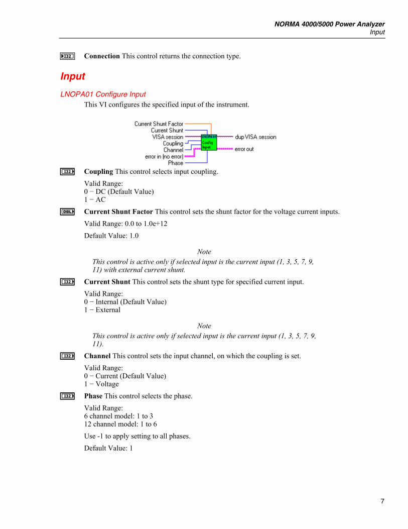
LNOPA01 Configure Input This VI configures the specified input of the instrument.
I Coupling This control selects input coupling.
Valid Range: 0 − DC (Default Value) 1 − AC
E Current Shunt Factor This control sets the shunt factor for the voltage current inputs. Valid Range: 0.0 to 1.0e+12 Default Value: 1.0
Note This control is active only if selected input is the current input (1, 3, 5, 7, 9, 11) with external current shunt.
I Current Shunt This control sets the shunt type for specified current input. Valid Range: 0 − Internal (Default Value) 1 − External
Note This control is active only if selected input is the current input (1, 3, 5, 7, 9, 11).
I Channel This control sets the input channel, on which the coupling is set. Valid Range: 0 − Current (Default Value) 1 − Voltage
I Phase This control selects the phase. Valid Range: 6 channel model: 1 to 3 12 channel model: 1 to 6 Use -1 to apply setting to all phases. Default Value: 1
LabVIEW Driver Reference Manual
8
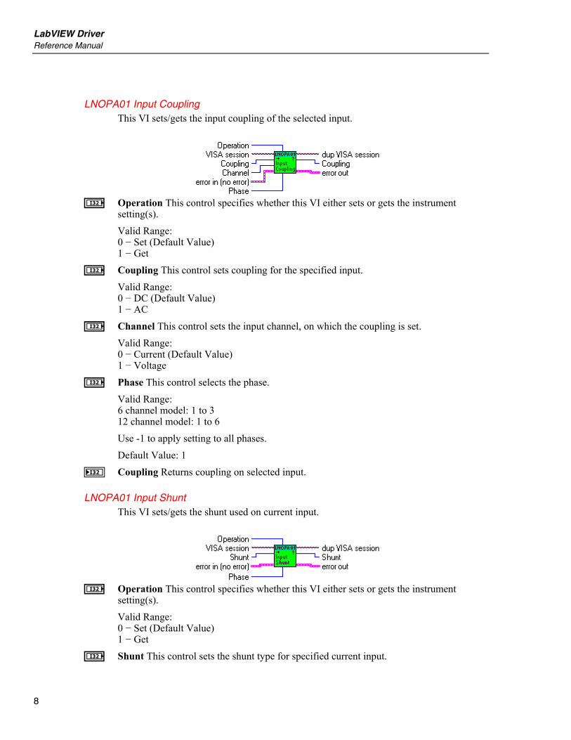
LNOPA01 Input Coupling This VI sets/gets the input coupling of the selected input.
I Operation This control specifies whether this VI either sets or gets the instrument
setting(s). Valid Range: 0 − Set (Default Value) 1 − Get
I Coupling This control sets coupling for the specified input. Valid Range: 0 − DC (Default Value) 1 − AC
I Channel This control sets the input channel, on which the coupling is set. Valid Range: 0 − Current (Default Value) 1 − Voltage
I Phase This control selects the phase. Valid Range: 6 channel model: 1 to 3 12 channel model: 1 to 6 Use -1 to apply setting to all phases. Default Value: 1
J Coupling Returns coupling on selected input.
LNOPA01 Input Shunt This VI sets/gets the shunt used on current input.
I Operation This control specifies whether this VI either sets or gets the instrument
setting(s). Valid Range: 0 − Set (Default Value) 1 − Get
I Shunt This control sets the shunt type for specified current input.
NORMA 4000/5000 Power Analyzer Input
9
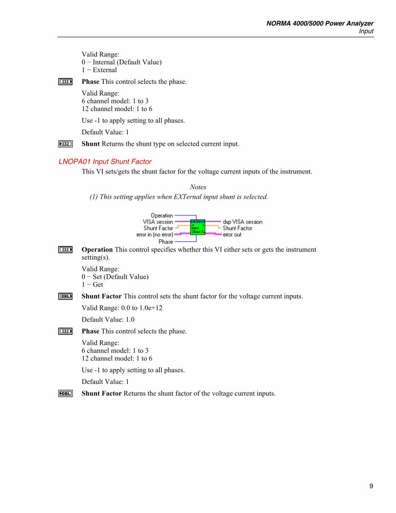
Valid Range: 0 − Internal (Default Value) 1 − External
I Phase This control selects the phase. Valid Range: 6 channel model: 1 to 3 12 channel model: 1 to 6 Use -1 to apply setting to all phases. Default Value: 1
J Shunt Returns the shunt type on selected current input.
LNOPA01 Input Shunt Factor This VI sets/gets the shunt factor for the voltage current inputs of the instrument.
Notes (1) This setting applies when EXTernal input shunt is selected.
I Operation This control specifies whether this VI either sets or gets the instrument
setting(s). Valid Range: 0 − Set (Default Value) 1 − Get
E Shunt Factor This control sets the shunt factor for the voltage current inputs. Valid Range: 0.0 to 1.0e+12 Default Value: 1.0
I Phase This control selects the phase. Valid Range: 6 channel model: 1 to 3 12 channel model: 1 to 6 Use -1 to apply setting to all phases. Default Value: 1
F Shunt Factor Returns the shunt factor of the voltage current inputs.
LabVIEW Driver Reference Manual
10
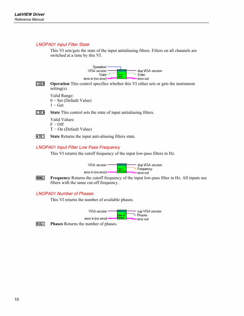
LNOPA01 Input Filter State This VI sets/gets the state of the input antialiasing filters. Filters on all channels are switched at a time by this VI.
I Operation This control specifies whether this VI either sets or gets the instrument
setting(s). Valid Range: 0 − Set (Default Value) 1 − Get
e State This control sets the state of input antialiasing filters. Valid Values: F − Off T − On (Default Value)
f State Returns the input anti-aliasing filters state.
LNOPA01 Input Filter Low Pass Frequency This VI returns the cutoff frequency of the input low-pass filters in Hz.
F Frequency Returns the cutoff frequency of the input low-pass filter in Hz. All inputs use
filters with the same cut-off frequency.
LNOPA01 Number of Phases This VI returns the number of available phases.
J Phases Returns the number of phases.
NORMA 4000/5000 Power Analyzer Range
11
Range
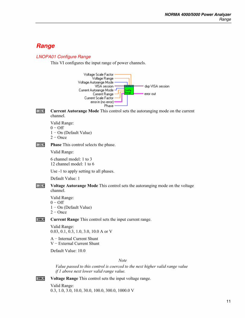
LNOPA01 Configure Range This VI configures the input range of power channels.
I Current Autorange Mode This control sets the autoranging mode on the current
channel. Valid Range: 0 − Off 1 − On (Default Value) 2 − Once
I Phase This control selects the phase. Valid Range: 6 channel model: 1 to 3 12 channel model: 1 to 6 Use -1 to apply setting to all phases. Default Value: 1
I Voltage Autorange Mode This control sets the autoranging mode on the voltage channel. Valid Range: 0 − Off 1 − On (Default Value) 2 − Once
E Current Range This control sets the input current range. Valid Range: 0.03, 0.1, 0.3, 1.0, 3.0, 10.0 A or V A − Internal Current Shunt V − External Current Shunt Default Value: 10.0
Note Value passed to this control is coerced to the next higher valid range value if 1 above next lower valid range value.
E Voltage Range This control sets the input voltage range. Valid Range: 0.3, 1.0, 3.0, 10.0, 30.0, 100.0, 300.0, 1000.0 V
LabVIEW Driver Reference Manual
12
Default Value: 1000.0
Note Value passed to this control is coerced to the next higher valid range value if 1% above next lower valid range value.
E Current Scale Factor This control sets the current scaling factor. Valid Range: 0.0 to 1.0e12 Default Value: 1.0
E Voltage Scale Factor This control sets the voltage scaling factor. Valid Range: 0.0 to 1.0e12 Default Value: 1.0
LNOPA01 Range Auto This VI sets/gets auto ranging mode of selected input channel.
I Operation This control specifies whether this VI either sets or gets the instrument setting(s). Valid Range: 0 − Set (Default Value) 1 − Get
I Mode This control sets the autoranging mode on the selected channel. Valid Range: 0 − Off 1 − On (Default Value) 2 − Once
I Channel This control sets the input channel, on which the range is set. Valid Range: 0 − Current (Default Value) 1 − Voltage
I Phase This control selects the phase. Valid Range: 6 channel model: 1 to 3 12 channel model: 1 to 6 Use -1 to apply setting to all phases. Default Value: 1
J Mode Returns the autoranging mode.
NORMA 4000/5000 Power Analyzer Range
13
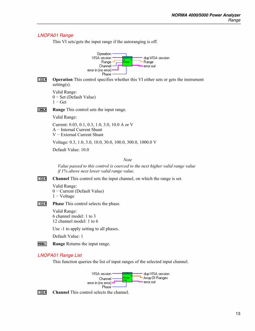
LNOPA01 Range This VI sets/gets the input range if the autoranging is off.
I Operation This control specifies whether this VI either sets or gets the instrument
setting(s). Valid Range: 0 − Set (Default Value) 1 − Get
E Range This control sets the input range. Valid Range: Current: 0.03, 0.1, 0.3, 1.0, 3.0, 10.0 A or V A − Internal Current Shunt V − External Current Shunt Voltage: 0.3, 1.0, 3.0, 10.0, 30.0, 100.0, 300.0, 1000.0 V Default Value: 10.0
Note Value passed to this control is coerced to the next higher valid range value if 1% above next lower valid range value.
I Channel This control sets the input channel, on which the range is set. Valid Range: 0 − Current (Default Value) 1 − Voltage
I Phase This control selects the phase. Valid Range: 6 channel model: 1 to 3 12 channel model: 1 to 6 Use -1 to apply setting to all phases. Default Value: 1
F Range Returns the input range.
LNOPA01 Range List This function queries the list of input ranges of the selected input channel.
I Channel This control selects the channel.
LabVIEW Driver Reference Manual
14
Valid Range: 0 - Current (Default Value) 1 - Voltage
I Phase This control selects the phase. Valid Range: 6 channel model: 1 to 3 12 channel model: 1 to 6 Default Value: 1
G Array Of Ranges Returns an array of valid ranges for selected channel in basic units (A or V). F Range This indicator returns the input range.
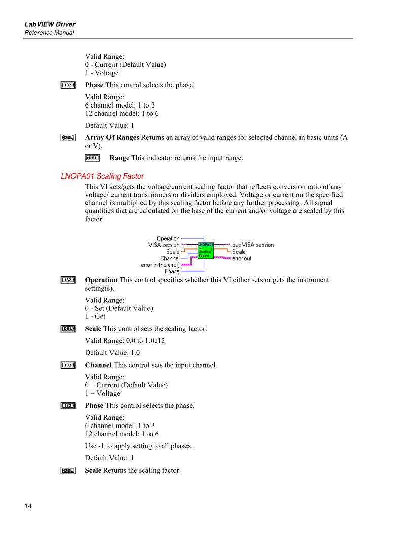
LNOPA01 Scaling Factor This VI sets/gets the voltage/current scaling factor that reflects conversion ratio of any voltage/ current transformers or dividers employed. Voltage or current on the specified channel is multiplied by this scaling factor before any further processing. All signal quantities that are calculated on the base of the current and/or voltage are scaled by this factor.
I Operation This control specifies whether this VI either sets or gets the instrument
setting(s). Valid Range: 0 - Set (Default Value) 1 - Get
E Scale This control sets the scaling factor. Valid Range: 0.0 to 1.0e12 Default Value: 1.0
I Channel This control sets the input channel. Valid Range: 0 − Current (Default Value) 1 − Voltage
I Phase This control selects the phase. Valid Range: 6 channel model: 1 to 3 12 channel model: 1 to 6 Use -1 to apply setting to all phases. Default Value: 1
F Scale Returns the scaling factor.

NORMA 4000/5000 Power Analyzer Sync
15
Sync
LNOPA01 Configure Sync This VI configures the instrument synchronization system.
e State This control sets the synchronization state.
Valid Range: F − Off T − On (Default Value)
I Channel This control sets the input channel, on which the source filter frequency is set. Valid Range: 0 – Current 1 − Voltage (Default Value) 2 − External
I Phase This control selects the phase. Valid Range: 6 channel model: 1 to 3 12 channel model: 1 to 6 Default Value: 1
I Auto Search This control sets the synchronization mode. Valid Range: 0 − Off (Default Value) 1 − On 2 − Once
Note Off - Automatic sensing of synchronization source is off.
On - Instrument is continuously sensing the best synchronization source. Once - Instrument sets the best synchronization source when this function is called.
LNOPA01 Configure Sync Source This VI configures the instrument synchronization system.
E Level This control sets the synchronization level.
Valid Range: −150% to 150% of input range Default Value: 0.0%

LabVIEW Driver Reference Manual
16
I Slope This control sets the active slope of the synchronization signal. Valid Range: 0 − Positive (Default Value) 1 − Negative
e Filter State This control sets the filter state. Valid Range: F − Off (Default Value) T − On
E Filter LP Frequency This control sets the synchronization source low-pass filter cutoff frequency. Valid Range: 10.0e3 Hz (Default Value) 1.0e3 Hz 100.0 Hz
Note Passed value is coerced to the next higher valid value if 10% above the next lower valid value.
LNOPA01 Sync State This VI sets/gets whether the averaging interval is controlled by signal frequency on selected input or not. If synchronization is turned on, the actual averaging period is kept to be a first integer multiple of the sync signal period greater than user-specified nominal averaging period. If synchronization is turned off, the actual averaging period is equal to the user-specified nominal averaging period rounded to integer multiple of sample periods.
I Operation This control specifies whether this VI either sets or gets the instrument
setting(s). Valid Range: 0 − Set (Default Value) 1 − Get
e State This control sets the synchronization state. Valid Range: F − Off T − On (Default Value)
f State Returns the synchronization state.
NORMA 4000/5000 Power Analyzer Sync
17
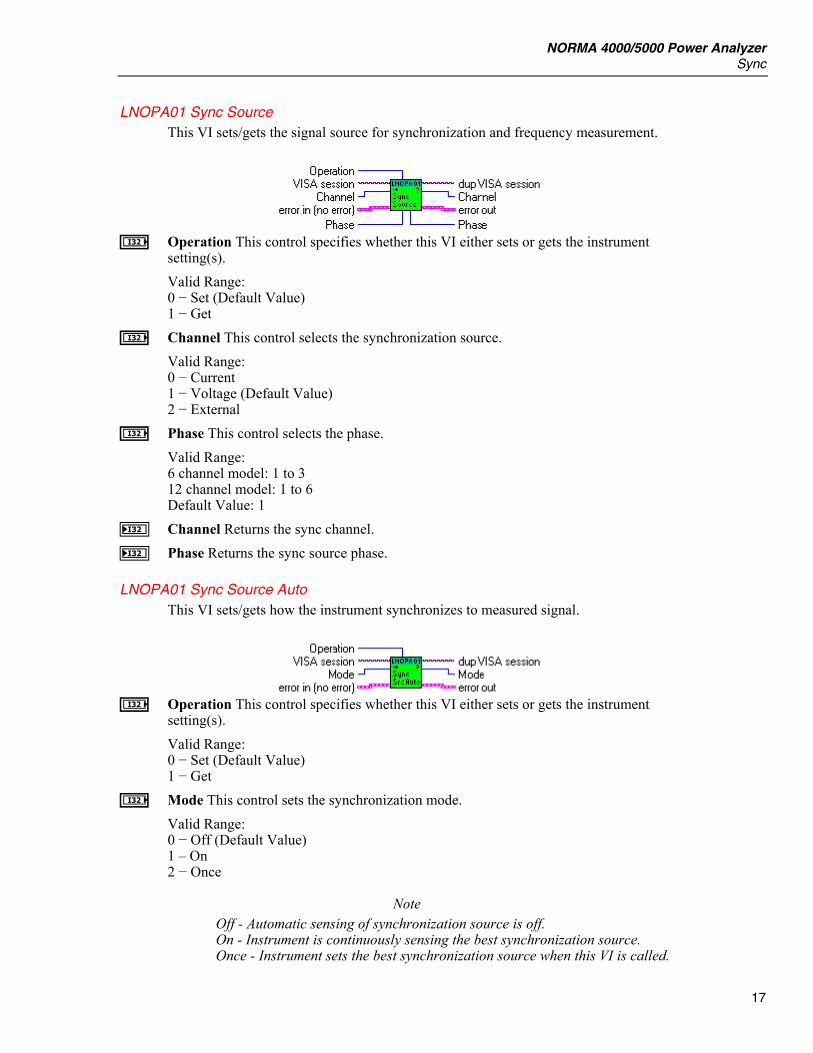
LNOPA01 Sync Source This VI sets/gets the signal source for synchronization and frequency measurement.
I Operation This control specifies whether this VI either sets or gets the instrument
setting(s). Valid Range: 0 − Set (Default Value) 1 − Get
I Channel This control selects the synchronization source. Valid Range: 0 − Current 1 − Voltage (Default Value) 2 − External
I Phase This control selects the phase. Valid Range: 6 channel model: 1 to 3 12 channel model: 1 to 6 Default Value: 1
J Channel Returns the sync channel. J Phase Returns the sync source phase.
LNOPA01 Sync Source Auto This VI sets/gets how the instrument synchronizes to measured signal.
I Operation This control specifies whether this VI either sets or gets the instrument
setting(s). Valid Range: 0 − Set (Default Value) 1 − Get
I Mode This control sets the synchronization mode. Valid Range: 0 − Off (Default Value) 1 – On 2 − Once
Note Off - Automatic sensing of synchronization source is off.
On - Instrument is continuously sensing the best synchronization source. Once - Instrument sets the best synchronization source when this VI is called.

LabVIEW Driver Reference Manual
18
J Mode Returns the synchronization mode.
LNOPA01 Sync Level This VI sets/gets the synchronization level at which the selected input signal period is measured by the synchronization circuitry of the instrument. Each input channel has its own synchronization level.
I Operation This control specifies whether this VI either sets or gets the instrument
setting(s). Valid Range: 0 − Set (Default Value) 1 − Get
E Level This control sets the synchronization level. Valid Range: -150% to 150% of input range Default Value: 0.0%
Note Depending on the selected sync level unit, this parameter can be set either as relative (in %) or absolute (in volts or amps). For relative unit, the range is -150.0 to 150.0. For absolute unit, the range is from -150% to 150% of the actual input range on the sync source channel.
F Level Returns the synchronization level.
LNOPA01 Sync Level Auto This VI sets/gets the automatic setting of the sync level. Each input channel has its own synchronization level mode setting.
I Operation This control specifies whether this VI either sets or gets the instrument
setting(s). Valid Range: 0 − Set (Default Value) 1 − Get
I Mode This control sets the sync level mode. Valid Range: 0 − Off (Default Value) 1 − On 2 − Once
NORMA 4000/5000 Power Analyzer Sync
19
Note Off − The sync level is fixed. On − The sync level is continuously adapted to signal. Once − When received, the instrument finds the best sync level and sets the automatic sync leveling to OFF.
J Mode Returns the sync level mode.
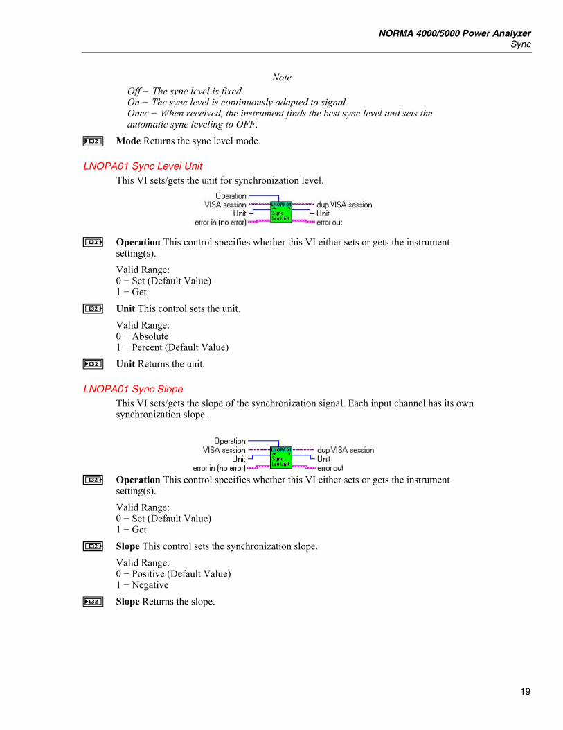
LNOPA01 Sync Level Unit This VI sets/gets the unit for synchronization level.
I Operation This control specifies whether this VI either sets or gets the instrument setting(s). Valid Range: 0 − Set (Default Value) 1 − Get
I Unit This control sets the unit. Valid Range: 0 − Absolute 1 − Percent (Default Value)
J Unit Returns the unit.
LNOPA01 Sync Slope This VI sets/gets the slope of the synchronization signal. Each input channel has its own synchronization slope.
I Operation This control specifies whether this VI either sets or gets the instrument
setting(s). Valid Range: 0 − Set (Default Value) 1 − Get
I Slope This control sets the synchronization slope. Valid Range: 0 − Positive (Default Value) 1 − Negative
J Slope Returns the slope.
LabVIEW Driver Reference Manual
20
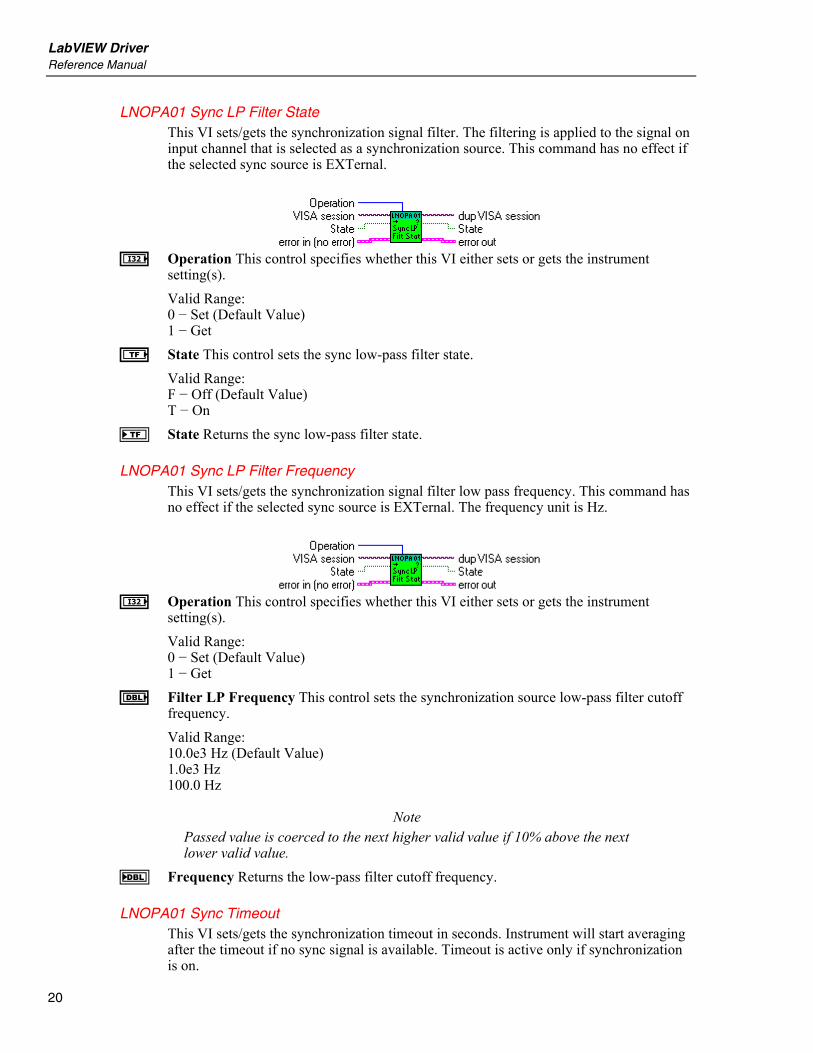
LNOPA01 Sync LP Filter State This VI sets/gets the synchronization signal filter. The filtering is applied to the signal on input channel that is selected as a synchronization source. This command has no effect if the selected sync source is EXTernal.
I Operation This control specifies whether this VI either sets or gets the instrument
setting(s). Valid Range: 0 − Set (Default Value) 1 − Get
e State This control sets the sync low-pass filter state. Valid Range: F − Off (Default Value) T − On
f State Returns the sync low-pass filter state.
LNOPA01 Sync LP Filter Frequency This VI sets/gets the synchronization signal filter low pass frequency. This command has no effect if the selected sync source is EXTernal. The frequency unit is Hz.
I Operation This control specifies whether this VI either sets or gets the instrument
setting(s). Valid Range: 0 − Set (Default Value) 1 − Get
E Filter LP Frequency This control sets the synchronization source low-pass filter cutoff frequency. Valid Range: 10.0e3 Hz (Default Value) 1.0e3 Hz 100.0 Hz
Note Passed value is coerced to the next higher valid value if 10% above the next lower valid value.
F Frequency Returns the low-pass filter cutoff frequency.
LNOPA01 Sync Timeout This VI sets/gets the synchronization timeout in seconds. Instrument will start averaging after the timeout if no sync signal is available. Timeout is active only if synchronization is on.
NORMA 4000/5000 Power Analyzer Sync
21
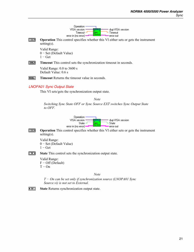
I Operation This control specifies whether this VI either sets or gets the instrument
setting(s). Valid Range: 0 − Set (Default Value) 1 − Get
E Timeout This control sets the synchronization timeout in seconds. Valid Range: 0.0 to 3600 s Default Value: 0.6 s
F Timeout Returns the timeout value in seconds.
LNOPA01 Sync Output State This VI sets/gets the synchronization output state.
Note Switching Sync State OFF or Sync Source EXT switches Sync Output State to OFF.
I Operation This control specifies whether this VI either sets or gets the instrument
setting(s). Valid Range: 0 − Set (Default Value) 1 − Get
e State This control sets the synchronization output state. Valid Range: F − Off (Default) T − On
Note T − On can be set only if synchronization source (LNOPA01 Sync Source.vi) is not set to External.
f State Returns synchronization output state.
LabVIEW Driver Reference Manual
22
Timebase
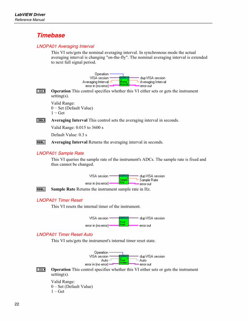
LNOPA01 Averaging Interval This VI sets/gets the nominal averaging interval. In synchronous mode the actual averaging interval is changing "on-the-fly". The nominal averaging interval is extended to next full signal period.
I Operation This control specifies whether this VI either sets or gets the instrument
setting(s). Valid Range: 0 − Set (Default Value) 1 − Get
E Averaging Interval This control sets the averaging interval in seconds. Valid Range: 0.015 to 3600 s Default Value: 0.3 s
F Averaging Interval Returns the averaging interval in seconds.
LNOPA01 Sample Rate This VI queries the sample rate of the instrument's ADCs. The sample rate is fixed and thus cannot be changed.
F Sample Rate Returns the instrument sample rate in Hz.
LNOPA01 Timer Reset This VI resets the internal timer of the instrument.
LNOPA01 Timer Reset Auto This VI sets/gets the instrument's internal timer reset state.
I Operation This control specifies whether this VI either sets or gets the instrument
setting(s). Valid Range: 0 – Set (Default Value) 1 – Get
NORMA 4000/5000 Power Analyzer Trigger
23
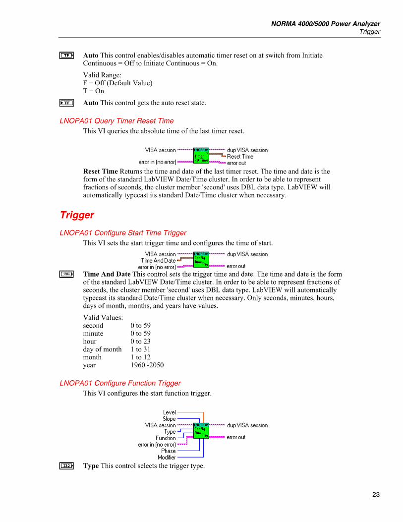
e Auto This control enables/disables automatic timer reset on at switch from Initiate Continuous = Off to Initiate Continuous = On. Valid Range: F − Off (Default Value) T − On
f Auto This control gets the auto reset state.
LNOPA01 Query Timer Reset Time This VI queries the absolute time of the last timer reset.
Reset Time Returns the time and date of the last timer reset. The time and date is the form of the standard LabVIEW Date/Time cluster. In order to be able to represent fractions of seconds, the cluster member 'second' uses DBL data type. LabVIEW will automatically typecast its standard Date/Time cluster when necessary.
Trigger
LNOPA01 Configure Start Time Trigger This VI sets the start trigger time and configures the time of start.
a Time And Date This control sets the trigger time and date. The time and date is the form
of the standard LabVIEW Date/Time cluster. In order to be able to represent fractions of seconds, the cluster member 'second' uses DBL data type. LabVIEW will automatically typecast its standard Date/Time cluster when necessary. Only seconds, minutes, hours, days of month, months, and years have values. Valid Values: second 0 to 59 minute 0 to 59 hour 0 to 23 day of month 1 to 31 month 1 to 12 year 1960 -2050
LNOPA01 Configure Function Trigger This VI configures the start function trigger.
I Type This control selects the trigger type.
LabVIEW Driver Reference Manual
24
Valid Values: 0 − Stop trigger 1 − Start trigger (Default Value)
I Function This control sets the type of voltage measurement function. Valid Range: 0 − Voltage True RMS (True RMS Voltage) 1 − Voltage Mean (Mean value of Voltage) 2 − Voltage Rectified Mean (Rectified Mean Voltage) 3 − Voltage Peak-To-Peak (Peak-to-peak Voltage) 4 − Voltage Highest Value (Highest value within averaging interval) 5 − Voltage Lowest Value (Lowest value within averaging interval) 6 − Voltage Crest Factor (Voltage Crest Factor) 7 − Voltage Absolute Phase (Voltage Absolute Phase) 8 − Voltage True RMS Phase-To-Phase (True RMS phase-to-phase Voltage) 9 − Voltage Harmonic 10 − Voltage TRMS Phase-To-Phase Harmonic 11 − Voltage Form Factor 12 − Voltage Harmonic Content 13 − Voltage Fundamental Content 14 − Voltage THD 15 − Current True RMS (True RMS Current) 16 − Current Mean (Mean value of Current) 17 − Current Rectified Mean (Rectified Mean Current) 18 − Current Peak-To-Peak (Peak-to-peak Current) 19 − Current Highest Value (Highest value within averaging interval) 20 − Current Lowest Value (Lowest value within averaging interval) 21 − Current Crest Factor 22 − Current Absolute Phase (Current Absolute Phase) 23 − Current Harmonic 24 − Current Form Factor 25 − Current Harmonic Content 26 − Current Fundamental Content 27 − Current THD 28 -Power Active (Active Power) 29 − Power Apparent (Apparent Power) 30 − Power Reactive (Reactive Power) 31 − Power Factor (Power Factor) 32 − Power Active Harmonic 33 − Power Apparent Harmonic 34 − Power Reactive Harmonic 35 − Power Factor Harmonic 36 − Power Corrected (Corrected Power) 37 − Phase 38 − Phase Harmonic 39 − Impedance 40 − Resistance Serial 41 − Resistance Parallel 42 − Reactance Serial 43 − Reactance Parallel 44 − Impedance Harmonic 45 − Resistance Serial Harmonic 46 − Resistance Parallel Harmonic 47 − Reactance Serial Harmonic 48 − Reactance Parallel Harmonic 49 − Frequency
NORMA 4000/5000 Power Analyzer Trigger
25
50 − Averaging Interval 51 − Shaft Torque [Nm] 52 − Rotational Speed [rpm] 53 − Mechanical Power [W] 54 − Rotational Asynchronousity [%] 55 − Motor Efficiency [%] 56 − Raw Process Input Value [V/Hz] 57 − Voltage Mean Phase-To-Phase 58 − Voltage Rectified Mean Phase-To-Phase 59 − Voltage Form Factor Phase-To-Phase 60 − Averaging Interval Relative Timestamp 61 − Electrical Efficiency 62 − Electrical Efficiency Harmonic 63 − True RMS Voltage Without DC 64 − True RMS Current Without DC 65 − Voltage THD Phase-To-Phase 66 − Voltage Harmonic Content Phase-To-Phase 67 − Voltage Fundamental Content Phase-To-Phase
Note Values 51 to 56 are available only with option Process Interface.
I Phase This control specifies the phase number. Valid Range: For Measurement: 0 − Voltage True RMS (True RMS Voltage) 1 − Voltage Mean (Mean value of Voltage) 2 − Voltage Rectified Mean (Rectified Mean Voltage) 3 − Voltage Peak-To-Peak (Peak-to-peak Voltage) 4 − Voltage Highest Value (Highest value within averaging interval) 5 − Voltage Lowest Value (Lowest value within averaging interval) 6 − Voltage Crest Factor (Voltage Crest Factor) 7 − Voltage Absolute Phase (Voltage Absolute Phase) 9 − Voltage Harmonic 15 − Current True RMS (True RMS Current) 16 − Current Mean (Mean value of Current) 17 − Current Rectified Mean (Rectified Mean Current) 18 − Current Peak-To-Peak (Peak-to-peak Current) 19 − Current Highest Value (Highest value within averaging interval) 20 − Current Lowest Value (Lowest value within averaging interval) 21 − Current Crest Factor 22 − Current Absolute Phase (Current Absolute Phase) 23 − Current Harmonic 28 − Power Active (Active Power) 29 − Power Apparent (Apparent Power) 30 − Power Reactive (Reactive Power) 31 − Power Factor (Power Factor) 32 − Power Active Harmonic 33 − Power Apparent Harmonic 34 − Power Reactive Harmonic 35 − Power Factor Harmonic 36 − Power Corrected (Corrected Power) 37 − Phase 38 − Phase Harmonic

LabVIEW Driver Reference Manual
26
39 − Impedance 40 − Resistance Serial 41 − Resistance Parallel 42 − Reactance Serial 43 − Reactance Parallel 44 − Impedance Harmonic 45 − Resistance Serial Harmonic 46 − Resistance Parallel Harmonic 47 − Reactance Serial Harmonic 48 − Reactance Parallel Harmonic 63 − True RMS Voltage Without DC 64 − True RMS Current Without DC
are Valid Values -1 : Sum of 1st 3-phase system (phase 1 … phase 3) 460: Sum of 2nd 3-phase system (phase 4 … phase 6) 1 to 3: for three channel model 1 to 6: for six channel model For Measurement: 11 − Voltage Form Factor 12 − Voltage Harmonic Content 13 − Voltage Fundamental Content 14 − Voltage THD 24 − Current Form Factor 25 − Current Harmonic Content 26 − Current Fundamental Content 27 − Current THD are Valid Values: 1 to 3: for three channel model 1 to 6: for six channel model For Measurement: 8 − Voltage True RMS Phase-To-Phase (True RMS phase-to-phase Voltage) 10 − Voltage TRMS Phase-To-Phase Harmonic 57 − Voltage Mean Phase-To-Phase 58 − Voltage Rectified Mean Phase-To-Phase 59 − Voltage Form Factor Phase-To-Phase are Valid Values: 12, 23, 31, 123: for three channel model 12, 23, 31, 45, 56, 64, 123, 456: for six channel model For Measurement: 49 -Frequency 50 − Averaging Interval 60 − Averaging Interval Relative Timestamp is valid -1 only For Measurements: 51 − Shaft Torque [Nm] 52 − Rotational Speed [rpm] 53 − Mechanical Power [W] 54 − Rotational Asynchronousity [%] 55 − Motor Efficiency [%] are valid values: 1 to 4, the values are independent of number of phases
NORMA 4000/5000 Power Analyzer Trigger
27
For Measurement: 56 -Raw Process Input Value [V/Hz] are valid values: 1 to 8, the values are independent of number of phases For Measurements: 61 − Electrical Efficiency 62 − Electrical Efficiency Harmonic are Valid Values: -1 : Sum of 1st 3-phase system (phase 1 … phase 3) 460: Sum of 2nd 3-phase system (phase 4 … phase 6) For Measurements: 65 − Voltage THD Phase-To-Phase 66 − Voltage Harmonic Content Phase-To-Phase 67 − Voltage Fundamental Content Phase-To-Phase are Valid Values: 12, 23, 31: for three channel model 12, 23, 31, 45, 56, 64: for six channel model
I Modifier This control specifies the modifier of voltage measurement function.
Note Only None, Positive Integral and Negative Integral are available now.
Valid Range: For Measurement: 1 − Voltage Mean (Mean value of Voltage) 16 − Current Mean (Mean value of Current) 28 − Power Active (Active Power) 29 − Power Apparent (Apparent Power) 30 − Power Reactive (Reactive Power) 32 − Power Active Harmonic 33 − Power Apparent Harmonic 34 − Power Reactive Harmonic are Valid Values 0 − None 1 − Minimum 2 − Maximum 3 − Integral Positive 4 − Integral Negative 5 − Integral For Measurement: 0 − Voltage True RMS (True RMS Voltage) 2 − Voltage Rectified Mean (Rectified Mean Voltage) 3 − Voltage Peak-To-Peak (Peak-to-peak Voltage) 4 − Voltage Highest Value (Highest value within averaging interval) 5 − Voltage Lowest Value (Lowest value within averaging interval) 6 − Voltage Crest Factor (Voltage Crest Factor) 7 − Voltage Absolute Phase (Voltage Absolute Phase) 8 − Voltage True RMS Phase-To-Phase (True RMS phase-to-phase Voltage) 9 − Voltage Harmonic 10 − Voltage TRMS Phase-To-Phase Harmonic 11 − Voltage Form Factor

LabVIEW Driver Reference Manual
28
12 − Voltage Harmonic Content 13 − Voltage Fundamental Content 14 − Voltage THD 15 − Current True RMS (True RMS Current) 17 − Current Rectified Mean (Rectified Mean Current) 18 − Current Peak-To-Peak (Peak-to-peak Current) 19 − Current Highest Value (Highest value within averaging interval) 20 − Current Lowest Value (Lowest value within averaging interval) 21 − Current Crest Factor 22 − Current Absolute Phase (Current Absolute Phase) 23 − Current Harmonic 24 − Current Form Factor 25 − Current Harmonic Content 26 − Current Fundamental Content 27 − Current THD 31 − Power Factor (Power Factor) 35 − Power Factor Harmonic 36 − Power Corrected (Corrected Power) 37 − Phase 38 − Phase Harmonic 39 − Impedance 40 − Resistance Serial 41 − Resistance Parallel 42 − Reactance Serial 43 − Reactance Parallel 44 − Impedance Harmonic 45 − Resistance Serial Harmonic 46 − Resistance Parallel Harmonic 47 − Reactance Serial Harmonic 48 − Reactance Parallel Harmonic 49 − Frequency 51 -Shaft Torque [Nm] 52 − Rotational Speed [rpm] 53 − Mechanical Power [W] 54 − Rotational Asynchronousity [%] 55 − Motor Efficiency [%] 56 − Raw Process Input Value [V/Hz] 57 − Voltage Mean Phase-To-Phase 58 − Voltage Rectified Mean Phase-To-Phase 59 − Voltage Form Factor Phase-To-Phase 61 − Electrical Efficiency 62 − Electrical Efficiency Harmonic 63 − True RMS Voltage Without DC 64 − True RMS Current Without DC 65 − Voltage THD Phase-To-Phase 66 − Voltage Harmonic Content Phase-To-Phase 67 − Voltage Fundamental Content Phase-To-Phase are Valid Values: 0 − None 1 − Minimum 2 − Maximum For Measurement: 50 − Averaging Intervals 60 − Averaging Interval Relative Timestamp
NORMA 4000/5000 Power Analyzer Trigger
29
is Valid Value: 0 − None
Note The integral modifiers are available only if integration is enabled.
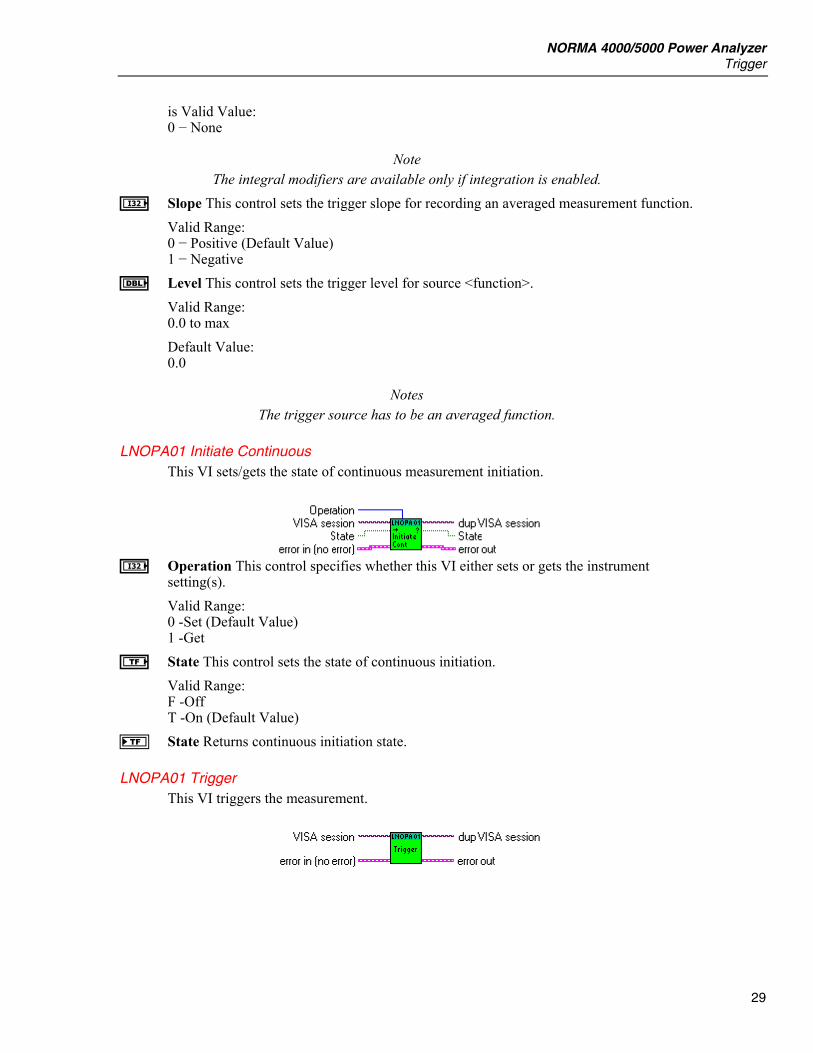
I Slope This control sets the trigger slope for recording an averaged measurement function. Valid Range: 0 − Positive (Default Value) 1 − Negative
E Level This control sets the trigger level for source <function>. Valid Range: 0.0 to max Default Value: 0.0
Notes The trigger source has to be an averaged function.
LNOPA01 Initiate Continuous This VI sets/gets the state of continuous measurement initiation.
I Operation This control specifies whether this VI either sets or gets the instrument
setting(s). Valid Range: 0 -Set (Default Value) 1 -Get
e State This control sets the state of continuous initiation. Valid Range: F -Off T -On (Default Value)
f State Returns continuous initiation state.
LNOPA01 Trigger This VI triggers the measurement.
LabVIEW Driver Reference Manual
30
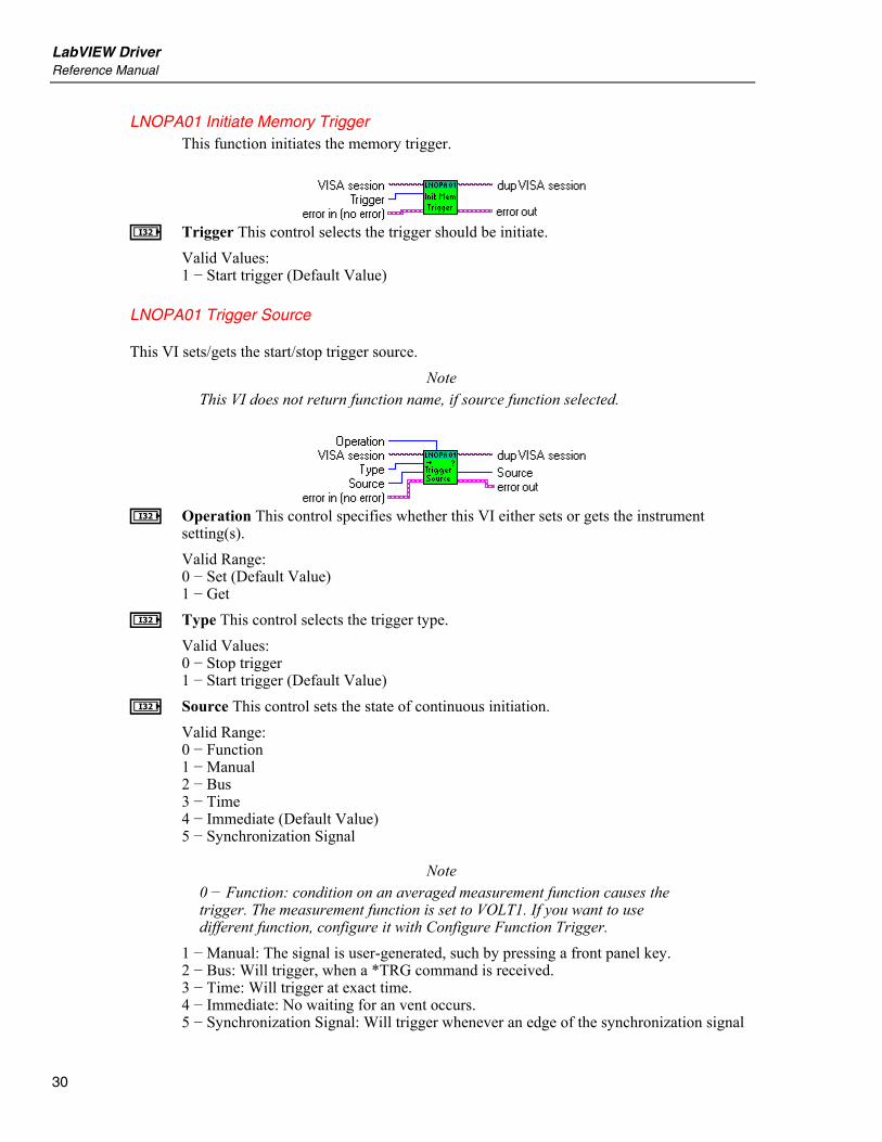
LNOPA01 Initiate Memory Trigger This function initiates the memory trigger.
I Trigger This control selects the trigger should be initiate.
Valid Values: 1 − Start trigger (Default Value)
LNOPA01 Trigger Source
This VI sets/gets the start/stop trigger source.
Note This VI does not return function name, if source function selected.
I Operation This control specifies whether this VI either sets or gets the instrument
setting(s). Valid Range: 0 − Set (Default Value) 1 − Get
I Type This control selects the trigger type. Valid Values: 0 − Stop trigger 1 − Start trigger (Default Value)
I Source This control sets the state of continuous initiation. Valid Range: 0 − Function 1 − Manual 2 − Bus 3 − Time 4 − Immediate (Default Value) 5 − Synchronization Signal
Note 0 − Function: condition on an averaged measurement function causes the trigger. The measurement function is set to VOLT1. If you want to use different function, configure it with Configure Function Trigger.
1 − Manual: The signal is user-generated, such by pressing a front panel key. 2 − Bus: Will trigger, when a *TRG command is received. 3 − Time: Will trigger at exact time. 4 − Immediate: No waiting for an vent occurs. 5 − Synchronization Signal: Will trigger whenever an edge of the synchronization signal
NORMA 4000/5000 Power Analyzer Trigger
31
is detected. This source is valid only for REALtime sweep (to use the EXTernal signal jack as a trigger the SYNC source have to be set to EXTernal).
J Source Returns the state of continuous initiation.
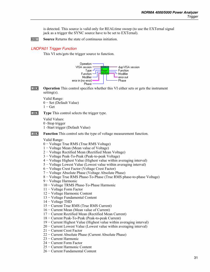
LNOPA01 Trigger Function This VI sets/gets the trigger source to function.
I Operation This control specifies whether this VI either sets or gets the instrument
setting(s). Valid Range: 0 − Set (Default Value) 1 − Get
I Type This control selects the trigger type. Valid Values: 0 -Stop trigger 1 -Start trigger (Default Value)
I Function This control sets the type of voltage measurement function. Valid Range: 0 − Voltage True RMS (True RMS Voltage) 1 − Voltage Mean (Mean value of Voltage) 2 − Voltage Rectified Mean (Rectified Mean Voltage) 3 − Voltage Peak-To-Peak (Peak-to-peak Voltage) 4 − Voltage Highest Value (Highest value within averaging interval) 5 − Voltage Lowest Value (Lowest value within averaging interval) 6 − Voltage Crest Factor (Voltage Crest Factor) 7 − Voltage Absolute Phase (Voltage Absolute Phase) 8 − Voltage True RMS Phase-To-Phase (True RMS phase-to-phase Voltage) 9 − Voltage Harmonic 10 − Voltage TRMS Phase-To-Phase Harmonic 11 − Voltage Form Factor 12 − Voltage Harmonic Content 13 − Voltage Fundamental Content 14 − Voltage THD 15 − Current True RMS (True RMS Current) 16 − Current Mean (Mean value of Current) 17 − Current Rectified Mean (Rectified Mean Current) 18 − Current Peak-To-Peak (Peak-to-peak Current) 19 − Current Highest Value (Highest value within averaging interval) 20 − Current Lowest Value (Lowest value within averaging interval) 21 − Current Crest Factor 22 − Current Absolute Phase (Current Absolute Phase) 23 − Current Harmonic 24 − Current Form Factor 25 − Current Harmonic Content 26 − Current Fundamental Content
LabVIEW Driver Reference Manual
32
27 − Current TH 28 − Power Active (Active Power) 29 − Power Apparent (Apparent Power) 30 − Power Reactive (Reactive Power) 31 − Power Factor (Power Factor) 32 − Power Active Harmonic 33 − Power Apparent Harmonic 34 − Power Reactive Harmonic 35 − Power Factor Harmonic 36 − Power Corrected (Corrected Power) 37 − Phase 38 − Phase Harmonic 39 − Impedance 40 − Resistance Serial 41 − Resistance Parallel 42 − Reactance Serial 43 − Reactance Parallel 44 − Impedance Harmonic 45 − Resistance Serial Harmonic 46 − Resistance Parallel Harmonic 47 − Reactance Serial Harmonic 48 − Reactance Parallel Harmonic 49 − Frequency 50 − Averaging Interval 51 − Shaft Torque [Nm] 52 − Rotational Speed [rpm] 53 − Mechanical Power [W] 54 − Rotational Asynchronousity [%] 55 − Motor Efficiency [%] 56 − Raw Process Input Value [V/Hz] 57 − Voltage Mean Phase-To-Phase 58 − Voltage Rectified Mean Phase-To-Phase 59 − Voltage Form Factor Phase-To-Phase 60 − Averaging Interval Relative Timestamp 61 − Electrical Efficiency 62 -Electrical Efficiency Harmonic 63 − True RMS Voltage Without DC 64 − True RMS Current Without DC 65 − Voltage THD Phase-To-Phase 66 − Voltage Harmonic Content Phase-To-Phase 67 − Voltage Fundamental Content Phase-To-Phase
Note Values 51 to 56 are available only with option Process Interface.
I Phase This control specifies the phase number. Valid Range: For Measurement: 0 − Voltage True RMS (True RMS Voltage) 1 − Voltage Mean (Mean value of Voltage) 2 − Voltage Rectified Mean (Rectified Mean Voltage) 3 − Voltage Peak-To-Peak (Peak-to-peak Voltage) 4 − Voltage Highest Value (Highest value within averaging interval) 5 − Voltage Lowest Value (Lowest value within averaging interval) 6 − Voltage Crest Factor (Voltage Crest Factor) 7 − Voltage Absolute Phase (Voltage Absolute Phase)

NORMA 4000/5000 Power Analyzer Trigger
33
9 − Voltage Harmonic 15 − Current True RMS (True RMS Current) 16 − Current Mean (Mean value of Current) 17 − Current Rectified Mean (Rectified Mean Current) 18 − Current Peak-To-Peak (Peak-to-peak Current) 19 − Current Highest Value (Highest value within averaging interval) 20 − Current Lowest Value (Lowest value within averaging interval) 21 − Current Crest Factor 22 − Current Absolute Phase (Current Absolute Phase) 23 − Current Harmonic 28 − Power Active (Active Power) 29 − Power Apparent (Apparent Power) 30 − Power Reactive (Reactive Power) 31 − Power Factor (Power Factor) 32 − Power Active Harmonic 33 − Power Apparent Harmonic 34 − Power Reactive Harmonic 35 − Power Factor Harmonic 36 − Power Corrected (Corrected Power) 37 − Phase 38 − Phase Harmonic 39 − Impedance 40 − Resistance Serial 41 − Resistance Parallel 42 − Reactance Serial 43 − Reactance Parallel 44 − Impedance Harmonic 45 − Resistance Serial Harmonic 46 − Resistance Parallel Harmonic 47 − Reactance Serial Harmonic 48 − Reactance Parallel Harmonic 63 − True RMS Voltage Without DC 64 − True RMS Current Without DC are Valid Values -1 : Sum of 1st 3-phase system (phase 1 … phase 3) 460: Sum of 2nd 3-phase system (phase 4 … phase 6) 1 to 3: for three channel model 1 to 6: for six channel model For Measurement: 11 − Voltage Form Factor 12 − Voltage Harmonic Content 13 − Voltage Fundamental Content 14 − Voltage THD 24 − Current Form Factor 25 − Current Harmonic Content 26 − Current Fundamental Content 27 − Current THD are Valid Values: 1 to 3: for three channel model 1 to 6: for six channel model For Measurement: 8 − Voltage True RMS Phase-To-Phase (True RMS phase-to-phase Voltage) 10 − Voltage TRMS Phase-To-Phase Harmonic
LabVIEW Driver Reference Manual
34
57 − Voltage Mean Phase-To-Phase 58 − Voltage Rectified Mean Phase-To-Phase 59 − Voltage Form Factor Phase-To-Phase are Valid Values: 12, 23, 31, 123: for three channel model 12, 23, 31, 45, 56, 64, 123, 456: for six channel model For Measurement: 49 − Frequency 50 − Averaging Interval 60 − Averaging Interval Relative Timestamp is valid -1 only For Measurements: 51 − Shaft Torque [Nm] 52 − Rotational Speed [rpm] 53 − Mechanical Power [W] 54 − Rotational Asynchronousity [%] 55 − Motor Efficiency [%] are valid values: 1 to 4, the values are independent of number of phases For Measurement: 56 -Raw Process Input Value [V/Hz] are valid values: 1 to 8, the values are independent of number of phases For Measurements: 61 − Electrical Efficiency 62 − Electrical Efficiency Harmonic are Valid Values: -1 : Sum of 1st 3-phase system (phase 1 … phase 3) 460: Sum of 2nd 3-phase system (phase 4 … phase 6) For Measurements: 65 -Voltage THD Phase-To-Phase 66 -Voltage Harmonic Content Phase-To-Phase 67 -Voltage Fundamental Content Phase-To-Phase are Valid Values: 12, 23, 31: for three channel model 12, 23, 31, 45, 56, 64: for six channel model
I Modifier This control specifies the modifier of voltage measurement function.
Note Only None, Positive Integral and Negative Integral are available now.
Valid Range: For Measurement: 1 − Voltage Mean (Mean value of Voltage) 16 − Current Mean (Mean value of Current) 28 − Power Active (Active Power) 29 − Power Apparent (Apparent Power) 30 − Power Reactive (Reactive Power) 32 − Power Active Harmonic
NORMA 4000/5000 Power Analyzer Trigger
35
33 − Power Apparent Harmonic 34 − Power Reactive Harmonic are Valid Values 0 − None 1 − Minimum 2 − Maximum 3 − Integral Positive 4 − Integral Negative 5 − Integral For Measurement: 0 − Voltage True RMS (True RMS Voltage) 2 − Voltage Rectified Mean (Rectified Mean Voltage) 3 − Voltage Peak-To-Peak (Peak-to-peak Voltage) 4 − Voltage Highest Value (Highest value within averaging interval) 5 − Voltage Lowest Value (Lowest value within averaging interval) 6 − Voltage Crest Factor (Voltage Crest Factor) 7 − Voltage Absolute Phase (Voltage Absolute Phase) 8 − Voltage True RMS Phase-To-Phase (True RMS phase-to-phase Voltage) 9 − Voltage Harmonic 10 − Voltage TRMS Phase-To-Phase Harmonic 11 − Voltage Form Factor 12 − Voltage Harmonic Content 13 − Voltage Fundamental Content 14 − Voltage THD 15 − Current True RMS (True RMS Current) 17 − Current Rectified Mean (Rectified Mean Current) 18 − Current Peak-To-Peak (Peak-to-peak Current) 19 − Current Highest Value (Highest value within averaging interval) 20 − Current Lowest Value (Lowest value within averaging interval) 21 − Current Crest Factor 22 − Current Absolute Phase (Current Absolute Phase) 23 − Current Harmonic 24 − Current Form Factor 25 − Current Harmonic Content 26 − Current Fundamental Content 27 − Current THD 31 − Power Factor (Power Factor) 35 − Power Factor Harmonic 36 − Power Corrected (Corrected Power) 37 − Phase 38 − Phase Harmonic 39 − Impedance 40 − Resistance Serial 41 − Resistance Parallel 42 − Reactance Serial 43 − Reactance Parallel 44 − -Impedance Harmonic 45 − Resistance Serial Harmonic 46 − Resistance Parallel Harmonic 47 − Reactance Serial Harmonic 48 − Reactance Parallel Harmonic 49 − Frequency 51 − Shaft Torque [Nm] 52 − Rotational Speed [rpm]
LabVIEW Driver Reference Manual
36
53 − Mechanical Power [W] 54 − Rotational Asynchronousity [%] 55 − Motor Efficiency [%] 56 − Raw Process Input Value [V/Hz] 57 − Voltage Mean Phase-To-Phase 58 − Voltage Rectified Mean Phase-To-Phase 59 − Voltage Form Factor Phase-To-Phase 61 − Electrical Efficiency 62 − Electrical Efficiency Harmonic 63 − True RMS Voltage Without DC 64 − True RMS Current Without DC 65 − Voltage THD Phase-To-Phase 66 − Voltage Harmonic Content Phase-To-Phase 67 − Voltage Fundamental Content Phase-To-Phase are Valid Values: 0 − None 1 − Minimum 2 − Maximum For Measurement: 50 − Averaging Intervals 60 − Averaging Interval Relative Timestamp is Valid Value: 0 − None
Note The integral modifiers are available only if integration is enabled.
J Function This control sets the type of voltage measurement function. Valid Range: 0 − Voltage True RMS (True RMS Voltage) 1 − Voltage Mean (Mean value of Voltage) 2 − Voltage Rectified Mean (Rectified Mean Voltage) 3 − Voltage Peak-To-Peak (Peak-to-peak Voltage) 4 − Voltage Highest Value (Highest value within averaging interval) 5 − Voltage Lowest Value (Lowest value within averaging interval) 6 − Voltage Crest Factor (Voltage Crest Factor) 7 − Voltage Absolute Phase (Voltage Absolute Phase) 8 − Voltage True RMS Phase-To-Phase (True RMS phase-to-phase Voltage) 9 − Voltage Harmonic 10 − Voltage TRMS Phase-To-Phase Harmonic 11 − Voltage Form Factor 12 − Voltage Harmonic Content 13 − Voltage Fundamental Content 14 − Voltage THD 15 − Current True RMS (True RMS Current) 16 − Current Mean (Mean value of Current) 17 − Current Rectified Mean (Rectified Mean Current) 18 − Current Peak-To-Peak (Peak-to-peak Current) 19 − Current Highest Value (Highest value within averaging interval) 20 − Current Lowest Value (Lowest value within averaging interval) 21 − Current Crest Factor 22 − Current Absolute Phase (Current Absolute Phase) 23 − Current Harmonic
NORMA 4000/5000 Power Analyzer Trigger
37
24 − Current Form Factor 25 − Current Harmonic Content 26 − Current Fundamental Content 27 − Current THD 28 − Power Active (Active Power) 29 − Power Apparent (Apparent Power) 30 − Power Reactive (Reactive Power) 31 − Power Factor (Power Factor) 32 − Power Active Harmonic 33 − Power Apparent Harmonic 34 − Power Reactive Harmonic 35 − Power Factor Harmonic 36 − Power Corrected (Corrected Power) 37 − Phase 38 − Phase Harmonic 39 − Impedance 40 − Resistance Serial 41 − Resistance Parallel 42 − Reactance Serial 43 − Reactance Parallel 44 − Impedance Harmonic 45 − Resistance Serial Harmonic 46 − Resistance Parallel Harmonic 47 − Reactance Serial Harmonic 48 − Reactance Parallel Harmonic 49 − Frequency 50 − Averaging Interval 51 − Shaft Torque [Nm] 52 − Rotational Speed [rpm] 53 − Mechanical Power [W] 54 − Rotational Asynchronousity [%] 55 − Motor Efficiency [%] 56 − Raw Process Input Value [V/Hz] 57 − Voltage Mean Phase-To-Phase 58 − Voltage Rectified Mean Phase-To-Phase 59 − Voltage Form Factor Phase-To-Phase 60 − Averaging Interval Relative Timestamp 61 − Electrical Efficiency 62 − Electrical Efficiency Harmonic 63 − True RMS Voltage Without DC 64 − True RMS Current Without DC 65 − Voltage THD Phase-To-Phase 66 − Voltage Harmonic Content Phase-To-Phase 67 − Voltage Fundamental Content Phase-To-Phase
Note Values 51 to 56 are available only with option Process Interface.
J Phase This control specifies the phase number. Valid Range: For Measurement: 0 − Voltage True RMS (True RMS Voltage) 1 − Voltage Mean (Mean value of Voltage) 2 − Voltage Rectified Mean (Rectified Mean Voltage) 3 − Voltage Peak-To-Peak (Peak-to-peak Voltage)

LabVIEW Driver Reference Manual
38
4 − Voltage Highest Value (Highest value within averaging interval) 5 − Voltage Lowest Value (Lowest value within averaging interval) 6 − Voltage Crest Factor (Voltage Crest Factor) 7 − Voltage Absolute Phase (Voltage Absolute Phase) 9 − Voltage Harmonic 15 − Current True RMS (True RMS Current) 16 − Current Mean (Mean value of Current) 17 − Current Rectified Mean (Rectified Mean Current) 18 − Current Peak-To-Peak (Peak-to-peak Current) 19 − Current Highest Value (Highest value within averaging interval) 20 − Current Lowest Value (Lowest value within averaging interval) 21 − Current Crest Factor 22 − Current Absolute Phase (Current Absolute Phase) 23 − Current Harmonic 28 − Power Active (Active Power) 29 − Power Apparent (Apparent Power) 30 − Power Reactive (Reactive Power) 31 − Power Factor (Power Factor) 32 − Power Active Harmonic 33 − Power Apparent Harmonic 34 − Power Reactive Harmonic 35 − Power Factor Harmonic 36 − Power Corrected (Corrected Power) 37 − Phase 38 − Phase Harmonic 39 − Impedance 40 − Resistance Serial 41 − Resistance Parallel 42 − Reactance Serial 43 − Reactance Parallel 44 − Impedance Harmonic 45 − Resistance Serial Harmonic 46 − Resistance Parallel Harmonic 47 − Reactance Serial Harmonic 48 − Reactance Parallel Harmonic 63 − True RMS Voltage Without DC 64 − True RMS Current Without DC are Valid Values -1 : Sum of 1st 3-phase system (phase 1 … phase 3) 460: Sum of 2nd 3-phase system (phase 4 … phase 6) 1 to 3: for three channel model 1 to 6: for six channel model For Measurement: 11 − Voltage Form Factor 12 − Voltage Harmonic Content 13 − Voltage Fundamental Content 14 − Voltage THD 24 − Current Form Factor 25 − Current Harmonic Content 26 − Current Fundamental Content 27 − Current THD

NORMA 4000/5000 Power Analyzer Trigger
39
are Valid Values: 1 to 3: for three channel model 1 to 6: for six channel model For Measurement: 8 − Voltage True RMS Phase-To-Phase (True RMS phase-to-phase Voltage) 10 − Voltage TRMS Phase-To-Phase Harmonic 57 − Voltage Mean Phase-To-Phase 58 − Voltage Rectified Mean Phase-To-Phase 59 − Voltage Form Factor Phase-To-Phase are Valid Values: 12, 23, 31, 123: for three channel model 12, 23, 31, 45, 56, 64, 123, 456: for six channel model For Measurement: 49 − Frequency 50 − Averaging Interval 60 − Averaging Interval Relative Timestamp is valid -1 only For Measurements: 51 − Shaft Torque [Nm] 52 − Rotational Speed [rpm] 53 − Mechanical Power [W] 54 − -Rotational Asynchronousity [%] 55 − Motor Efficiency [%] are valid values: 1 to 4, the values are independent of number of phases For Measurement: 56 − Raw Process Input Value [V/Hz] are valid values: 1 to 8, the values are independent of number of phases For Measurements: 61 − Electrical Efficiency 62 − Electrical Efficiency Harmonic are Valid Values: -1 : Sum of 1st 3-phase system (phase 1 … phase 3) 460: Sum of 2nd 3-phase system (phase 4 … phase 6) For Measurements: 65 − Voltage THD Phase-To-Phase 66 − Voltage Harmonic Content Phase-To-Phase 67 − Voltage Fundamental Content Phase-To-Phase are Valid Values: 12, 23, 31: for three channel model 12, 23, 31, 45, 56, 64: for six channel model
J Modifier This control specifies the modifier of voltage measurement function.
Note Only None, Positive Integral and Negative Integral are available now.
Valid Range: For Measurement:
LabVIEW Driver Reference Manual
40
1 − Voltage Mean (Mean value of Voltage) 16 − Current Mean (Mean value of Current) 28 − Power Active (Active Power) 29 − Power Apparent (Apparent Power) 30 − Power Reactive (Reactive Power) 32 − Power Active Harmonic 33 − Power Apparent Harmonic 34 − Power Reactive Harmonic are Valid Values 0 − None 1 − Minimum 2 − Maximum 3 − Integral Positive 4 − Integral Negative 5 − Integral For Measurement: 0 − Voltage True RMS (True RMS Voltage) 2 − Voltage Rectified Mean (Rectified Mean Voltage) 3 − Voltage Peak-To-Peak (Peak-to-peak Voltage) 4 − Voltage Highest Value (Highest value within averaging interval) 5 − Voltage Lowest Value (Lowest value within averaging interval) 6 − Voltage Crest Factor (Voltage Crest Factor) 7 − Voltage Absolute Phase (Voltage Absolute Phase) 8 − Voltage True RMS Phase-To-Phase (True RMS phase-to-phase Voltage) 9 − Voltage Harmonic 10 − Voltage TRMS Phase-To-Phase Harmonic 11 − Voltage Form Factor 12 − Voltage Harmonic Content 13 − Voltage Fundamental Content 14 − Voltage THD 15 − Current True RMS (True RMS Current) 17 − Current Rectified Mean (Rectified Mean Current) 18 − Current Peak-To-Peak (Peak-to-peak Current) 19 − Current Highest Value (Highest value within averaging interval) 20 − Current Lowest Value (Lowest value within averaging interval) 21 − Current Crest Factor 22 − Current Absolute Phase (Current Absolute Phase) 23 − Current Harmonic 24 − Current Form Factor 25 − Current Harmonic Content 26 − Current Fundamental Content 27 − Current THD 31 − Power Factor (Power Factor) 35 − Power Factor Harmonic 36 − Power Corrected (Corrected Power) 37 − Phase 38 − Phase Harmonic 39 − Impedance 40 − Resistance Serial 41 − Resistance Parallel 42 − Reactance Serial 43 − Reactance Parallel 44 − Impedance Harmonic 45 − Resistance Serial Harmonic
NORMA 4000/5000 Power Analyzer Trigger
41
46 − Resistance Parallel Harmonic 47 − Reactance Serial Harmonic 48 − Reactance Parallel Harmonic 49 − Frequency 51 − Shaft Torque [Nm] 52 − Rotational Speed [rpm] 53 − Mechanical Power [W] 54 − Rotational Asynchronousity [%] 55 − Motor Efficiency [%] 56 − Raw Process Input Value [V/Hz] 57 − Voltage Mean Phase-To-Phase 58 − Voltage Rectified Mean Phase-To-Phase 59 − Voltage Form Factor Phase-To-Phase 61 − Electrical Efficiency 62 − Electrical Efficiency Harmonic 63 − True RMS Voltage Without DC 64 − True RMS Current Without DC 65 − Voltage THD Phase-To-Phase 66 − Voltage Harmonic Content Phase-To-Phase 67 − Voltage Fundamental Content Phase-To-Phase are Valid Values: 0 − None 1 − Minimum 2 − Maximum For Measurement: 50 − Averaging Intervals 60 − Averaging Interval Relative Timestamp is Valid Value: 0 − None
Note The integral modifiers are available only if integration is enabled.
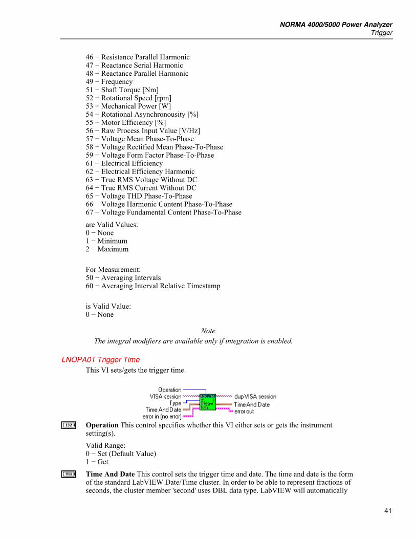
LNOPA01 Trigger Time This VI sets/gets the trigger time.
I Operation This control specifies whether this VI either sets or gets the instrument
setting(s). Valid Range: 0 − Set (Default Value) 1 − Get
a Time And Date This control sets the trigger time and date. The time and date is the form of the standard LabVIEW Date/Time cluster. In order to be able to represent fractions of seconds, the cluster member 'second' uses DBL data type. LabVIEW will automatically

LabVIEW Driver Reference Manual
42
typecast its standard Date/Time cluster when necessary. Only values second, minute, hour, day of month, month and year have Valid Values: seconds − 0 to 59 minute − 0 to 59 hour − 0to23 day of month − 1 to 31 month − 1to12 year − 1960 - 2050
I Type This control selects the trigger type. Valid Values: 1 − Start trigger (Default Value)
Note Only for start trigger can be set time.
b Time And Date Returns the trigger time and date. The time and date is the form of the standard LabVIEW Date/Time cluster. In order to be able to represent fractions of seconds, the cluster member 'second' uses DBL data type. LabVIEW will automatically typecast its standard Date/Time cluster when necessary.
LNOPA01 Trigger Level This VI sets/gets the trigger level.
I Operation This control specifies whether this VI either sets or gets the instrument
setting(s). Valid Range: 0 − Set (Default Value) 1 − Get
I Type This control selects the trigger type. Valid Values: 0 − Stop trigger 1 − Start trigger (Default Value)
E Level This control sets the trigger level for source <function>. Valid Range: 0.0 to max Default Value: 0.0
Note The trigger source has to be an averaged function.
F Level Returns the level for source <function>.

NORMA 4000/5000 Power Analyzer Status
43
Note The trigger source has to be an averaged function.
LNOPA01 Trigger Slope This VI sets/gets the trigger slope.
I Operation This control specifies whether this VI either sets or gets the instrument
setting(s). Valid Range: 0 − Set (Default Value) 1 − Get
I Type This control selects the trigger type. Valid Values: 0 − Stop trigger 1 − Start trigger (Default Value)
I Slope This control sets the trigger slope for recording an averaged measurement function. Valid Range: 0 − Positive (Default Value) 1 − Negative
J Slope Returns the trigger slope for recording an averaged measurement function.
Status
LNOPA01 Averaging Status This VI queries the averaging status synchronously or asynchronously. In synchronous mode, this VI waits for the averaging to complete.
E Timeout Specifies the timeout for averaging status query. If zero is passed, this function
does not wait for the averaging to complete. Non-zero value specifies the time this VI waits for the averaging to complete. The unit is seconds. If the averaging does not complete within this time, error 0xBFFC09F2 is generated.
J State Returns the averaging state.
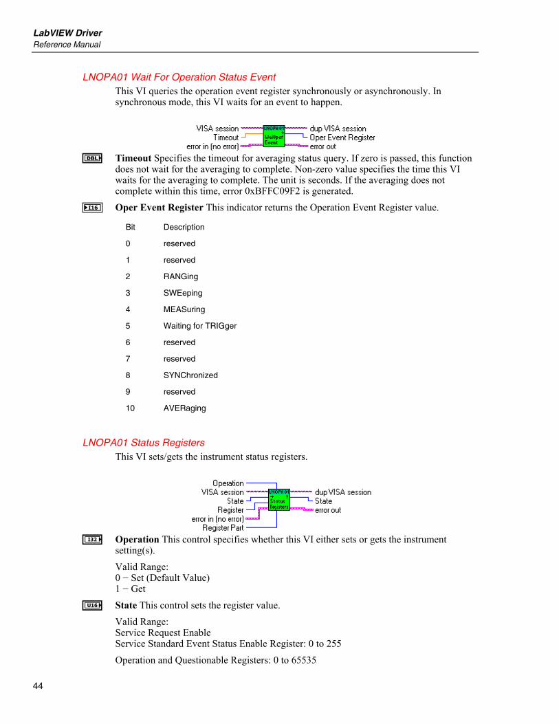
LabVIEW Driver Reference Manual
44
LNOPA01 Wait For Operation Status Event This VI queries the operation event register synchronously or asynchronously. In synchronous mode, this VI waits for an event to happen.
E Timeout Specifies the timeout for averaging status query. If zero is passed, this function
does not wait for the averaging to complete. Non-zero value specifies the time this VI waits for the averaging to complete. The unit is seconds. If the averaging does not complete within this time, error 0xBFFC09F2 is generated.
N Oper Event Register This indicator returns the Operation Event Register value.
Bit Description
0 reserved
1 reserved
2 RANGing
3 SWEeping
4 MEASuring
5 Waiting for TRIGger
6 reserved
7 reserved
8 SYNChronized
9 reserved
10 AVERaging
LNOPA01 Status Registers This VI sets/gets the instrument status registers.
I Operation This control specifies whether this VI either sets or gets the instrument
setting(s). Valid Range: 0 − Set (Default Value) 1 − Get
U State This control sets the register value. Valid Range: Service Request Enable Service Standard Event Status Enable Register: 0 to 255 Operation and Questionable Registers: 0 to 65535

NORMA 4000/5000 Power Analyzer Status
45
Note Condition and Event parts of cannot be set.
I Register This control sets the register. Valid Range: 0 − Status Byte 1 − Service Request Enable Service 2 − Standard Event Status Register 3 − Standard Event Status Enable Register 4 − Operation Status Register (Default Value) 5 − Questionable Status Register 6 − Questionable Voltage Status Register 7 − Questionable Current Status Register
Note Status Byte and Standard Event Status Register cannot be set.
I Register Part This control sets the register part. Valid Range: 0 − Condition 1 − Positive Transition 2 − Negative Transition 3 − Event 4 − Enable (Default Value)
Note (1) This control does not apply to STB, SRE, ESR and ESE registers. (2) Condition and Event parts cannot be set.
V State Returns the register value.
LNOPA01 Status Register Bit This VI sets one bit of status register and returns new register value.
U Bit This control sets the register bit.
Valid Range: Service Request Enable Service Standard Event Status Enable Register: 0 to 7 Operation and Questionable Registers: 0 to 15
I Register This control sets the register. Valid Range: 0 − Status Byte 1 − Service Request Enable Service 2 − Standard Event Status Register 3 − Standard Event Status Enable Register 4 − Operation Status Register (Default Value)

LabVIEW Driver Reference Manual
46
5 − Questionable Status Register 6 − Questionable Voltage Status Register 7 − Questionable Current Status Register
Note Status Byte and Standard Event Status Register can not be set.
I Register Part This control sets the register part. Valid Range: 0 − Condition 1 − Positive Transition 2 − Negative Transition 3 − Event 4 − Enable (Default Value)
Note This control does not apply to STB, SRE, ESR and ESE registers. Condition and Event parts cannot be set. Condition and Event parts cannot be set.
e Bit State V State Returns the register value.
Data Format
LNOPA01 Data Format This VI sets/gets the format of the measured data transferred from the instrument.
I Operation This control specifies whether this VI either sets or gets the instrument
setting(s). Valid Range: 0 − Set (Default Value) 1 − Get
I Format This control specifies the data type for data transfers. Valid Range: 0 − ASCII (Default Value) 1 − Binary
I Data Length This control specifies the length of data. Valid Range: ASCII: 0 to 8 decimal places in exponential notation Binary: 32 or 64 bits in FP format Default Value: 6
I Status Length This control specifies the data status information length.
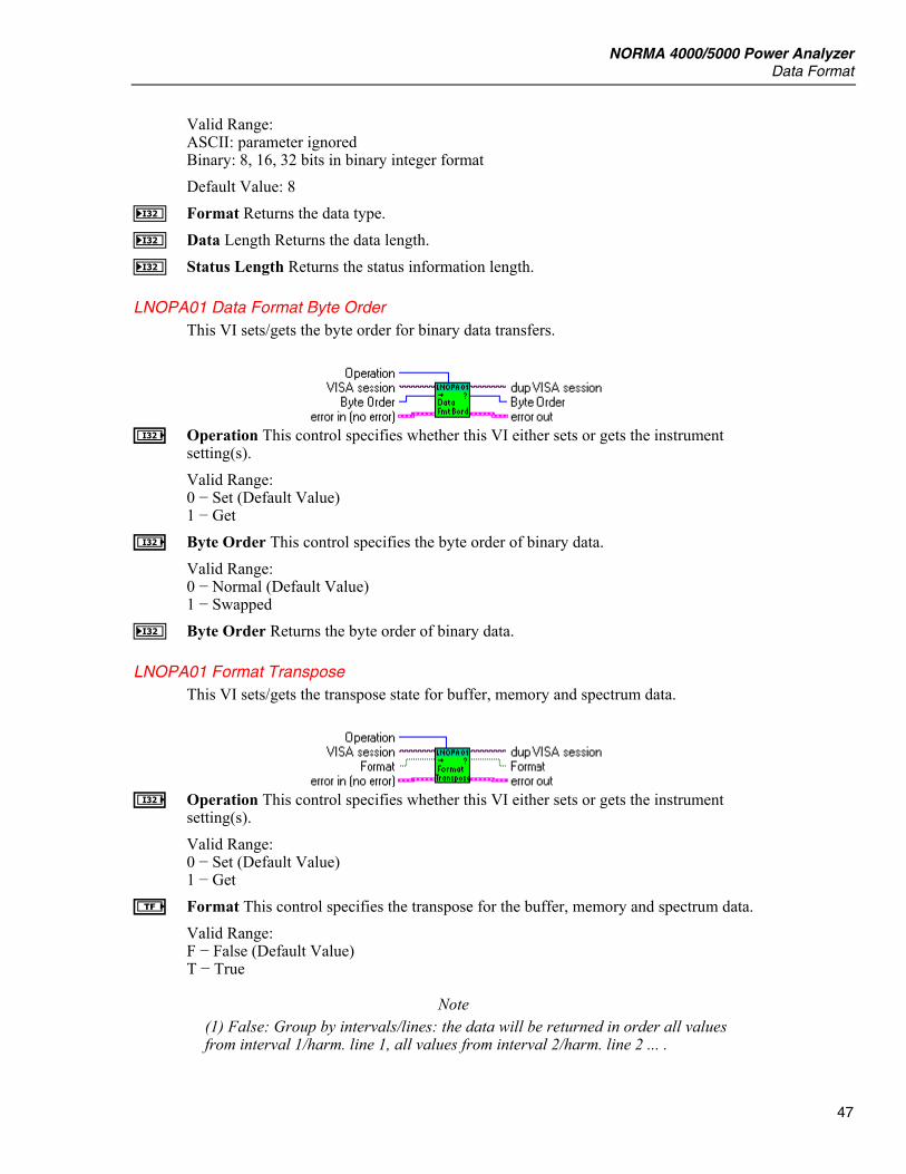
NORMA 4000/5000 Power Analyzer Data Format
47
Valid Range: ASCII: parameter ignored Binary: 8, 16, 32 bits in binary integer format Default Value: 8
J Format Returns the data type. J Data Length Returns the data length. J Status Length Returns the status information length.
LNOPA01 Data Format Byte Order This VI sets/gets the byte order for binary data transfers.
I Operation This control specifies whether this VI either sets or gets the instrument
setting(s). Valid Range: 0 − Set (Default Value) 1 − Get
I Byte Order This control specifies the byte order of binary data. Valid Range: 0 − Normal (Default Value) 1 − Swapped
J Byte Order Returns the byte order of binary data.
LNOPA01 Format Transpose This VI sets/gets the transpose state for buffer, memory and spectrum data.
I Operation This control specifies whether this VI either sets or gets the instrument
setting(s). Valid Range: 0 − Set (Default Value) 1 − Get
e Format This control specifies the transpose for the buffer, memory and spectrum data. Valid Range: F − False (Default Value) T − True
Note (1) False: Group by intervals/lines: the data will be returned in order all values from interval 1/harm. line 1, all values from interval 2/harm. line 2 ... .

LabVIEW Driver Reference Manual
48
(2) True: Group by measurement functions: the data will be returned in order all values/harm. lines of function 1, all values/harm. lines of function 2 ... .
f Format Returns the format setting. F − grouped by interval/harm. lines T − grouped by measurement functions
Measurement Function
LNOPA01 Measurement Functions This VI sets/gets the active measurement functions. Concurrent functions must be enabled if multiple functions are selected.
Note All input arrays to this VI must be of the same size.
L Measurement This control sets the array of voltage measurement function.
Valid Range: 0 − Voltage True RMS (True RMS Voltage) 1 − Voltage Mean (Mean value of Voltage) 2 − Voltage Rectified Mean (Rectified Mean Voltage) 3 − Voltage Peak-To-Peak (Peak-to-peak Voltage) 4 − Voltage Highest Value (Highest value within averaging interval) 5 − Voltage Lowest Value (Lowest value within averaging interval) 6 − Voltage Crest Factor (Voltage Crest Factor) 7 − Voltage Absolute Phase (Voltage Absolute Phase) 8 − Voltage True RMS Phase-To-Phase (True RMS phase-to-phase Voltage) 9 − Voltage Harmonic 10 − Voltage TRMS Phase-To-Phase Harmonic 11 − Voltage Form Factor 12 − Voltage Harmonic Content 13 − Voltage Fundamental Content 14 − Voltage THD 15 − Current True RMS (True RMS Current) 16 − Current Mean (Mean value of Current) 17 − Current Rectified Mean (Rectified Mean Current) 18 − Current Peak-To-Peak (Peak-to-peak Current) 19 − Current Highest Value (Highest value within averaging interval) 20 − Current Lowest Value (Lowest value within averaging interval) 21 − Current Crest Factor 22 − Current Absolute Phase (Current Absolute Phase) 23 − Current Harmonic 24 − Current Form Factor 25 − Current Harmonic Content 26 − Current Fundamental Content 27 − Current THD 28 − Power Active (Active Power)

NORMA 4000/5000 Power Analyzer Measurement Function
49
29 − Power Apparent (Apparent Power) 30 − Power Reactive (Reactive Power) 31 − Power Factor (Power Factor) 32 − Power Active Harmonic 33 − Power Apparent Harmonic 34 − Power Reactive Harmonic 35 − Power Factor Harmonic 36 − Power Corrected (Corrected Power) 37 − Phase 38 − Phase Harmonic 39 − Impedance 40 − Resistance Serial 41 − Resistance Parallel 42 − Reactance Serial 43 − Reactance Parallel 44 − Impedance Harmonic 45 − Resistance Serial Harmonic 46 − Resistance Parallel Harmonic 47 − Reactance Serial Harmonic 48 − Reactance Parallel Harmonic 49 − Frequency 50 − Averaging Interval 51 − Shaft Torque [Nm] 52 − Rotational Speed [rpm] 53 − Mechanical Power [W] 54 − Rotational Asynchronousity [%] 55 − Motor Efficiency [%] 56 − Raw Process Input Value [V/Hz] 57 − Voltage Mean Phase-To-Phase 58 − Voltage Rectified Mean Phase-To-Phase 59 − Voltage Form Factor Phase-To-Phase 60 − Averaging Interval Relative Timestamp 61 − Electrical Efficiency 62 − Electrical Efficiency Harmonic 63 − True RMS Voltage Without DC 64 − True RMS Current Without DC 65 − Voltage THD Phase-To-Phase 66 − Voltage Harmonic Content Phase-To-Phase 67 − Voltage Fundamental Content Phase-To-Phase
Note Values 51 to 56 are available only with option Process Interface.
L Phase This control specifies the array of phase numbers. Valid Range: For Measurement: 0 − Voltage True RMS (True RMS Voltage) 1 − Voltage Mean (Mean value of Voltage) 2 − Voltage Rectified Mean (Rectified Mean Voltage) 3 − Voltage Peak-To-Peak (Peak-to-peak Voltage) 4 − Voltage Highest Value (Highest value within averaging interval) 5 − Voltage Lowest Value (Lowest value within averaging interval) 6 − Voltage Crest Factor (Voltage Crest Factor) 7 − Voltage Absolute Phase (Voltage Absolute Phase)

LabVIEW Driver Reference Manual
50
9 − Voltage Harmonic 15 − Current True RMS (True RMS Current) 16 − Current Mean (Mean value of Current) 17 − Current Rectified Mean (Rectified Mean Current) 18 − Current Peak-To-Peak (Peak-to-peak Current) 19 − Current Highest Value (Highest value within averaging interval) 20 − Current Lowest Value (Lowest value within averaging interval) 21 − Current Crest Factor 22 − Current Absolute Phase (Current Absolute Phase) 23 − Current Harmonic 28 − Power Active (Active Power) 29 − Power Apparent (Apparent Power) 30 − Power Reactive (Reactive Power) 31 − Power Factor (Power Factor) 32 − Power Active Harmonic 33 − Power Apparent Harmonic 34 − Power Reactive Harmonic 35 − Power Factor Harmonic 36 − Power Corrected (Corrected Power) 37 − Phase 38 − Phase Harmonic 39 − Impedance 40 − Resistance Serial 41 − Resistance Parallel 42 − Reactance Serial 43 − Reactance Parallel 44 − Impedance Harmonic 45 − Resistance Serial Harmonic 46 − Resistance Parallel Harmonic 47 − Reactance Serial Harmonic 48 − Reactance Parallel Harmonic 63 − True RMS Voltage Without DC 64 − True RMS Current Without DC are Valid Values -1: Sum of 1st 3-phase system (phase 1 … phase 3) 460: Sum of 2nd 3-phase system (phase 4 … phase 6) 1 to 3: for three channel model 1 to 6: for six channel model For Measurement: 11 − Voltage Form Factor 12 − Voltage Harmonic Content 13 − Voltage Fundamental Content 14 − Voltage THD 24 − Current Form Factor 25 − Current Harmonic Content 26 − Current Fundamental Content 27 − Current THD are Valid Values: 1 to 3: for three channel model 1 to 6: for six channel model
NORMA 4000/5000 Power Analyzer Measurement Function
51
For Measurement: 8 − Voltage True RMS Phase-To-Phase (True RMS phase-to-phase Voltage) 10 − Voltage TRMS Phase-To-Phase Harmonic 57 − Voltage Mean Phase-To-Phase 58 − Voltage Rectified Mean Phase-To-Phase 59 − Voltage Form Factor Phase-To-Phase are Valid Values: 12, 23, 31, 123: for three channel model 12, 23, 31, 45, 56, 64, 123, 456: for six channel model For Measurement: 49 − Frequency 50 − Averaging Interval 60 − Averaging Interval Relative Timestamp is valid -1 only For Measurements: 51 − Shaft Torque [Nm] 52 − Rotational Speed [rpm] 53 − Mechanical Power [W] 54 − Rotational Asynchronousity [%] 55 − Motor Efficiency [%] are valid values: 1 to 4, the values are independent of number of phases For Measurement: 56 − Raw Process Input Value [V/Hz] are valid values: 1 to 8, the values are independent of number of phases For Measurements: 61 − Electrical Efficiency 62 − Electrical Efficiency Harmonic are Valid Values: -1: Sum of 1st 3-phase system (phase 1 … phase 3) 460: Sum of 2nd 3-phase system (phase 4 … phase 6) For Measurements: 65 − Voltage THD Phase-To-Phase 66 − Voltage Harmonic Content Phase-To-Phase 67 − Voltage Fundamental Content Phase-To-Phase are Valid Values: 12, 23, 31: for three channel model 12, 23, 31, 45, 56, 64: for six channel model
L Modifier This control specifies the array of modifiers of voltage measurement function.
Note Only None, Positive Integral and Negative Integral are available now.
Valid Range: For Measurement: 1 − Voltage Mean (Mean value of Voltage) 16 − Current Mean (Mean value of Current) 28 − Power Active (Active Power) 29 − Power Apparent (Apparent Power)
LabVIEW Driver Reference Manual
52
30 − Power Reactive (Reactive Power) 32 − Power Active Harmonic 33 − Power Apparent Harmonic 34 − Power Reactive Harmonic are Valid Values 0 − None 1 − Minimum 2 − Maximum 3 − Integral Positive 4 − Integral Negative 5 − Integral For Measurement: 0 − Voltage True RMS (True RMS Voltage) 2 − Voltage Rectified Mean (Rectified Mean Voltage) 3 − Voltage Peak-To-Peak (Peak-to-peak Voltage) 4 − Voltage Highest Value (Highest value within averaging interval) 5 − Voltage Lowest Value (Lowest value within averaging interval) 6 − Voltage Crest Factor (Voltage Crest Factor) 7 − Voltage Absolute Phase (Voltage Absolute Phase) 8 − Voltage True RMS Phase-To-Phase (True RMS phase-to-phase Voltage) 9 − Voltage Harmonic 10 − Voltage TRMS Phase-To-Phase Harmonic 11 − Voltage Form Factor 12 − Voltage Harmonic Content 13 − Voltage Fundamental Content 14 − Voltage THD 15 − Current True RMS (True RMS Current) 17 − Current Rectified Mean (Rectified Mean Current) 18 − Current Peak-To-Peak (Peak-to-peak Current) 19 − Current Highest Value (Highest value within averaging interval) 20 − Current Lowest Value (Lowest value within averaging interval) 21 − Current Crest Factor 22 − Current Absolute Phase (Current Absolute Phase) 23 − Current Harmonic 24 − Current Form Factor 25 − Current Harmonic Content 26 − Current Fundamental Content 27 − Current THD 31 − Power Factor (Power Factor) 35 − Power Factor Harmonic 36 – Power Corrected (Corrected Power) 37 − Phase 38 − Phase Harmonic 39 − Impedance 40 − Resistance Serial 41 − Resistance Parallel 42 − Reactance Serial 43 − Reactance Parallel 44 − Impedance Harmonic 45 − Resistance Serial Harmonic 46 − Resistance Parallel Harmonic 47 − Reactance Serial Harmonic 48 − Reactance Parallel Harmonic 49 − Frequency
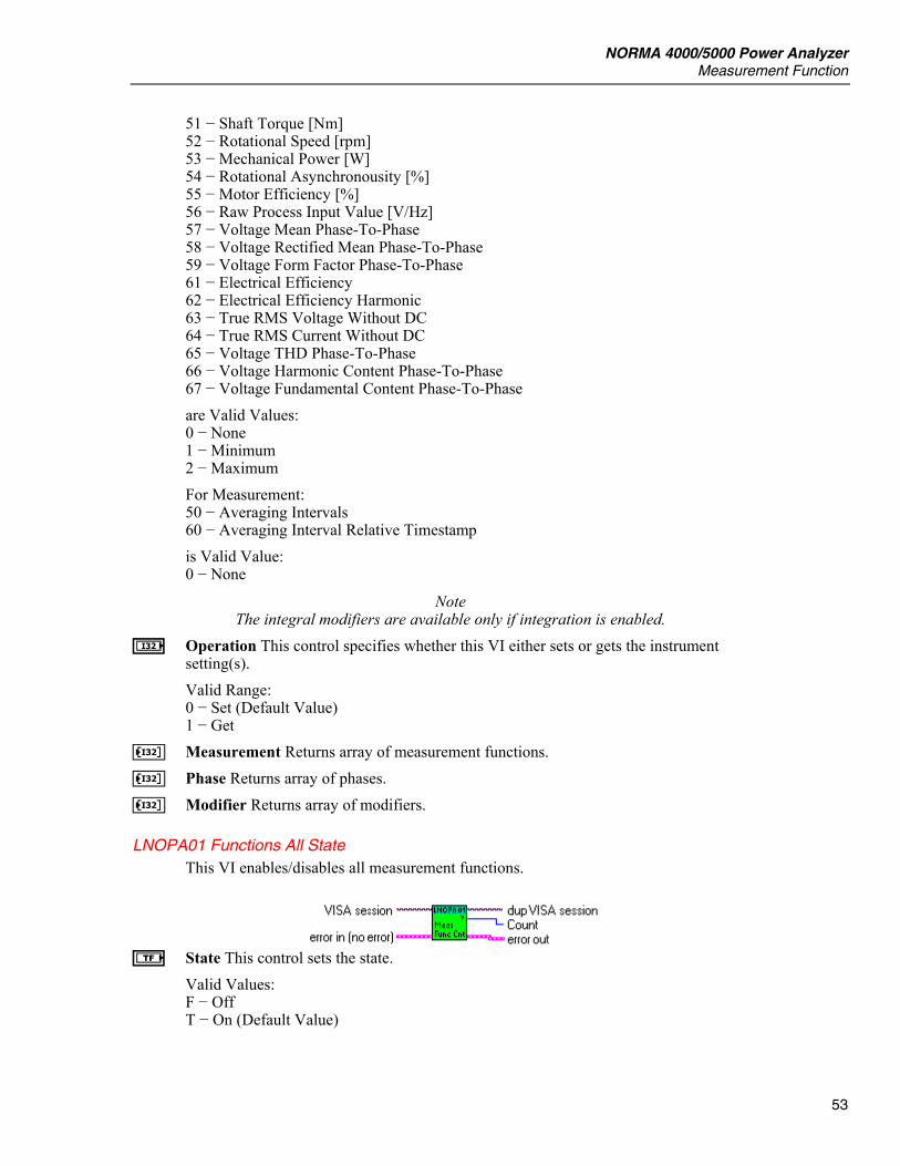
NORMA 4000/5000 Power Analyzer Measurement Function
53
51 − Shaft Torque [Nm] 52 − Rotational Speed [rpm] 53 − Mechanical Power [W] 54 − Rotational Asynchronousity [%] 55 − Motor Efficiency [%] 56 − Raw Process Input Value [V/Hz] 57 − Voltage Mean Phase-To-Phase 58 − Voltage Rectified Mean Phase-To-Phase 59 − Voltage Form Factor Phase-To-Phase 61 − Electrical Efficiency 62 − Electrical Efficiency Harmonic 63 − True RMS Voltage Without DC 64 − True RMS Current Without DC 65 − Voltage THD Phase-To-Phase 66 − Voltage Harmonic Content Phase-To-Phase 67 − Voltage Fundamental Content Phase-To-Phase are Valid Values: 0 − None 1 − Minimum 2 − Maximum For Measurement: 50 − Averaging Intervals 60 − Averaging Interval Relative Timestamp is Valid Value: 0 − None
Note The integral modifiers are available only if integration is enabled.
I Operation This control specifies whether this VI either sets or gets the instrument setting(s). Valid Range: 0 − Set (Default Value) 1 − Get
K Measurement Returns array of measurement functions. K Phase Returns array of phases. K Modifier Returns array of modifiers.
LNOPA01 Functions All State This VI enables/disables all measurement functions.
e State This control sets the state.
Valid Values: F − Off T − On (Default Value)

LabVIEW Driver Reference Manual
54
LNOPA01 Function Count This VI queries the number of measurement functions that are ON.
I Count Returns the number of measurement functions that are ON.
LNOPA01 Concurrent Functions State This VI sets/gets the concurrent functions state. The state must be On in order to be able to specify multiple measurement functions for readout from the instrument.
Note This VI configures whether the SENSor block should be configured to SENSe one function at a time or SENSe more than one function at a time (concurrently).
I Operation This control specifies whether this VI either sets or gets the instrument
setting(s). Valid Range: 0 − Set (Default Value) 1 − Get
e State This control sets the concurrent functions state. Valid Range: F − Off T − On (Default Value)
Note (1) On -the function(s) specified as parameter(s) to the LNOPA01 Measurement Functions.vi are turned on, while the state of other functions is set to off. (2) Off -the LNOPA01 Measurement Functions.vi acts as a one-of-n switch selecting the indicated function to be the only sensed function.
f State Returns the state of concurrent functions.
LNOPA01 Harmonic Order This VI sets/gets the harmonic order.
I Operation This control specifies whether this VI either sets or gets the instrument
setting(s).
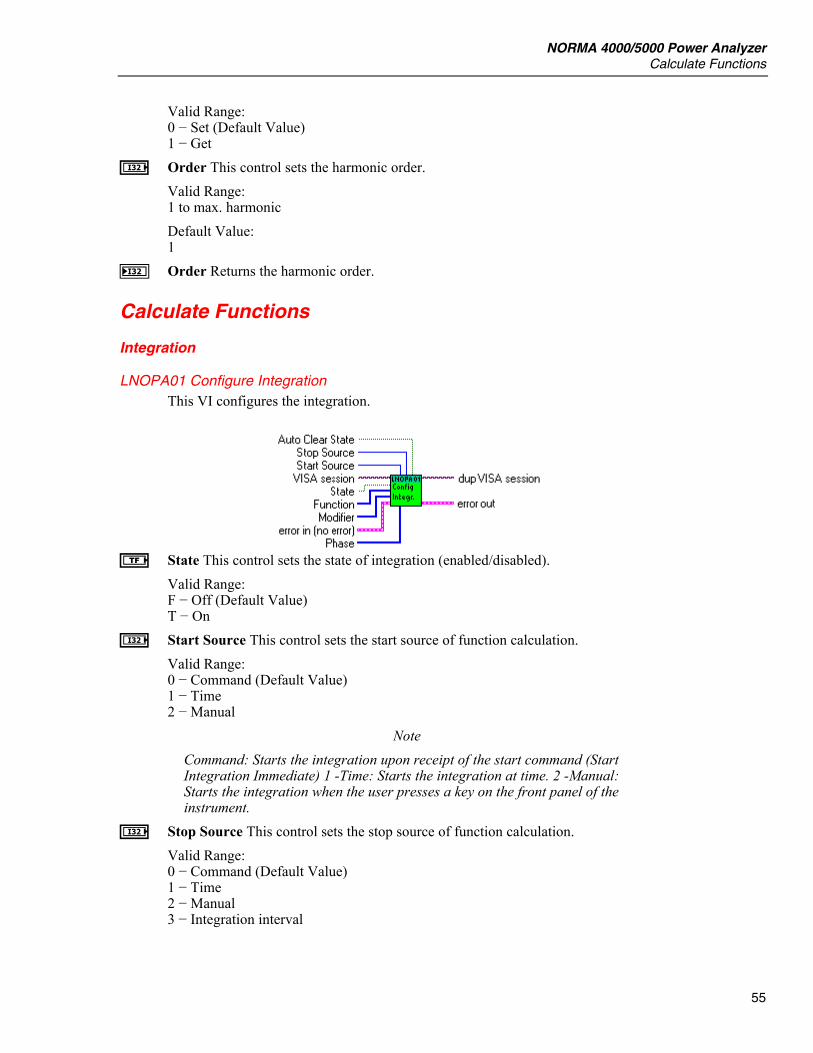
NORMA 4000/5000 Power Analyzer Calculate Functions
55
Valid Range: 0 − Set (Default Value) 1 − Get
I Order This control sets the harmonic order. Valid Range: 1 to max. harmonic Default Value: 1
J Order Returns the harmonic order.
Calculate Functions
Integration
LNOPA01 Configure Integration This VI configures the integration.
e State This control sets the state of integration (enabled/disabled).
Valid Range: F − Off (Default Value) T − On
I Start Source This control sets the start source of function calculation. Valid Range: 0 − Command (Default Value) 1 − Time 2 − Manual
Note Command: Starts the integration upon receipt of the start command (Start Integration Immediate) 1 -Time: Starts the integration at time. 2 -Manual: Starts the integration when the user presses a key on the front panel of the instrument.
I Stop Source This control sets the stop source of function calculation. Valid Range: 0 − Command (Default Value) 1 − Time 2 − Manual 3 − Integration interval

LabVIEW Driver Reference Manual
56
Note 0 − Command: Stops the integration upon receipt of the start command (Stop Integration Immediate). 1 − Time: Stops the integration at time. 2 − Manual: Stops the integration when the user presses a key on the front panel of the instrument. 3 − Integration interval: Stops the integration after interval.
e Auto Clear State This control sets the auto clear state. Valid Range: F − Off (Default Value) T − On
Note If On is set, the values are cleared at the start.
L Function This control specifies the array of measurement functions. Each element in the passed array should represent one measurement function. Valid Range: 1 − Mean Value Of Voltage 16 − Mean Value Of Current 28 − Active Power 29 − Apparent Power 30 − Reactive Power 32 − Active Power Harmonic 33 − Apparent Power Harmonic 34 − Reactive Power Harmonic
L Phase This control specifies the array of phases. Valid Values: -1: Sum of 1st 3-phase system (phase 1 … phase 3) 460: Sum of 2nd 3-phase system (phase 4 … phase 6) 1 to 3: for three channel model 1 to 6: for six channel model
L Modifier Not used now. For future use.
LNOPA01 Integration Functions This VI sets/gets the function list for the integral calculation.
Note All input arrays to this VI must be of the same size.
L Function This control specifies the array of measurement functions. Each element in the
passed array should represent one measurement function. Valid Range:

NORMA 4000/5000 Power Analyzer Calculate Functions
57
1 − Mean Value of Voltage 16 − Mean Value of Current 28 − Active Power 29 − Apparent Power 30 − Reactive Power 32 − Active Power Harmonic 33 − Apparent Power Harmonic 34 − Reactive Power Harmonic
L Phase This control specifies the array of phases. Valid Values: -1 : Sum of 1st 3-phase system (phase 1 … phase 3) 460: Sum of 2nd 3-phase system (phase 4 … phase 6) 1 to 3: for three channel model 1 to 6: for six channel model
L Modifier Not used now. For future use. I Operation This control specifies whether this VI either sets or gets the instrument
setting(s). Valid Range: 0 − Set (Default Value) 1 − Get
K Function Returns array of integration functions. K Phase Returns array of phases. K Modifier Returns array of modifiers.
LNOPA01 Integration State This VI sets/gets the state of integration.
I Operation This control specifies whether this VI either sets or gets the instrument
setting(s). Valid Range: 0 − Set (Default Value) 1 − Get
e State This control sets the state of integration (enabled/disabled). Valid Range: F − Off (Default Value) T − On
f State Returns the state of integration.
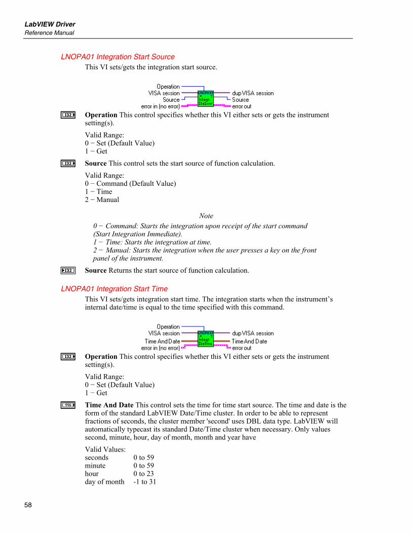
LabVIEW Driver Reference Manual
58
LNOPA01 Integration Start Source This VI sets/gets the integration start source.
I Operation This control specifies whether this VI either sets or gets the instrument
setting(s). Valid Range: 0 − Set (Default Value) 1 − Get
I Source This control sets the start source of function calculation. Valid Range: 0 − Command (Default Value) 1 − Time 2 − Manual
Note 0 − Command: Starts the integration upon receipt of the start command (Start Integration Immediate). 1 − Time: Starts the integration at time. 2 − Manual: Starts the integration when the user presses a key on the front panel of the instrument.
J Source Returns the start source of function calculation.
LNOPA01 Integration Start Time This VI sets/gets integration start time. The integration starts when the instrument’s internal date/time is equal to the time specified with this command.
I Operation This control specifies whether this VI either sets or gets the instrument
setting(s). Valid Range: 0 − Set (Default Value) 1 − Get
a Time And Date This control sets the time for time start source. The time and date is the form of the standard LabVIEW Date/Time cluster. In order to be able to represent fractions of seconds, the cluster member 'second' uses DBL data type. LabVIEW will automatically typecast its standard Date/Time cluster when necessary. Only values second, minute, hour, day of month, month and year have Valid Values: seconds 0 to 59 minute 0 to 59 hour 0 to 23 day of month -1 to 31

NORMA 4000/5000 Power Analyzer Calculate Functions
59
month 1 to 12 year 1960 to 2050
b Time And Date Returns the time for time start source. The time and date is the form of the standard LabVIEW Date/Time cluster. In order to be able to represent fractions of seconds, the cluster member 'second' uses DBL data type. LabVIEW will automatically typecast its standard Date/Time cluster when necessary.
LNOPA01 Integration Stop Source This VI sets/gets the integration stop source.
Note Stopping integration does not reset the integrated values to zero.
I Operation This control specifies whether this VI either sets or gets the instrument
setting(s). Valid Range: 0 − Set (Default Value) 1 − Get
I Source This control sets the stop source of function calculation. Valid Range: 0 − Command (Default Value) 1 − Time 2 − Manual 3 − Integration interval
Note 0 − Command: Stops the integration upon receipt of the start command (Stop Integration Immediate). 1 − Time: Stops the integration at time. 2 − Manual: Stops the integration when the user presses a key on the front panel of the instrument. 3 − Integration interval: Stops the integration after interval.
J Source Returns the stop source of function calculation.
LNOPA01 Integration Stop Time This VI sets/gets sets the integration stop time. The integration stops when the instrument’s internal date/time is equal to the time specified with this command.
I Operation This control specifies whether this VI either sets or gets the instrument
setting(s).
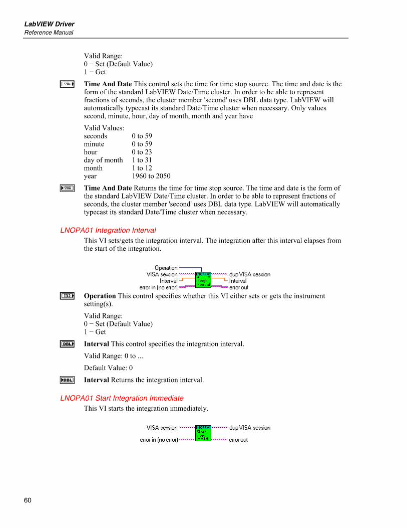
LabVIEW Driver Reference Manual
60
Valid Range: 0 − Set (Default Value) 1 − Get
a Time And Date This control sets the time for time stop source. The time and date is the form of the standard LabVIEW Date/Time cluster. In order to be able to represent fractions of seconds, the cluster member 'second' uses DBL data type. LabVIEW will automatically typecast its standard Date/Time cluster when necessary. Only values second, minute, hour, day of month, month and year have Valid Values: seconds 0 to 59 minute 0 to 59 hour 0 to 23 day of month 1 to 31 month 1 to 12 year 1960 to 2050
b Time And Date Returns the time for time stop source. The time and date is the form of the standard LabVIEW Date/Time cluster. In order to be able to represent fractions of seconds, the cluster member 'second' uses DBL data type. LabVIEW will automatically typecast its standard Date/Time cluster when necessary.
LNOPA01 Integration Interval This VI sets/gets the integration interval. The integration after this interval elapses from the start of the integration.
I Operation This control specifies whether this VI either sets or gets the instrument
setting(s). Valid Range: 0 − Set (Default Value) 1 − Get
E Interval This control specifies the integration interval. Valid Range: 0 to ... Default Value: 0
F Interval Returns the integration interval.
LNOPA01 Start Integration Immediate This VI starts the integration immediately.
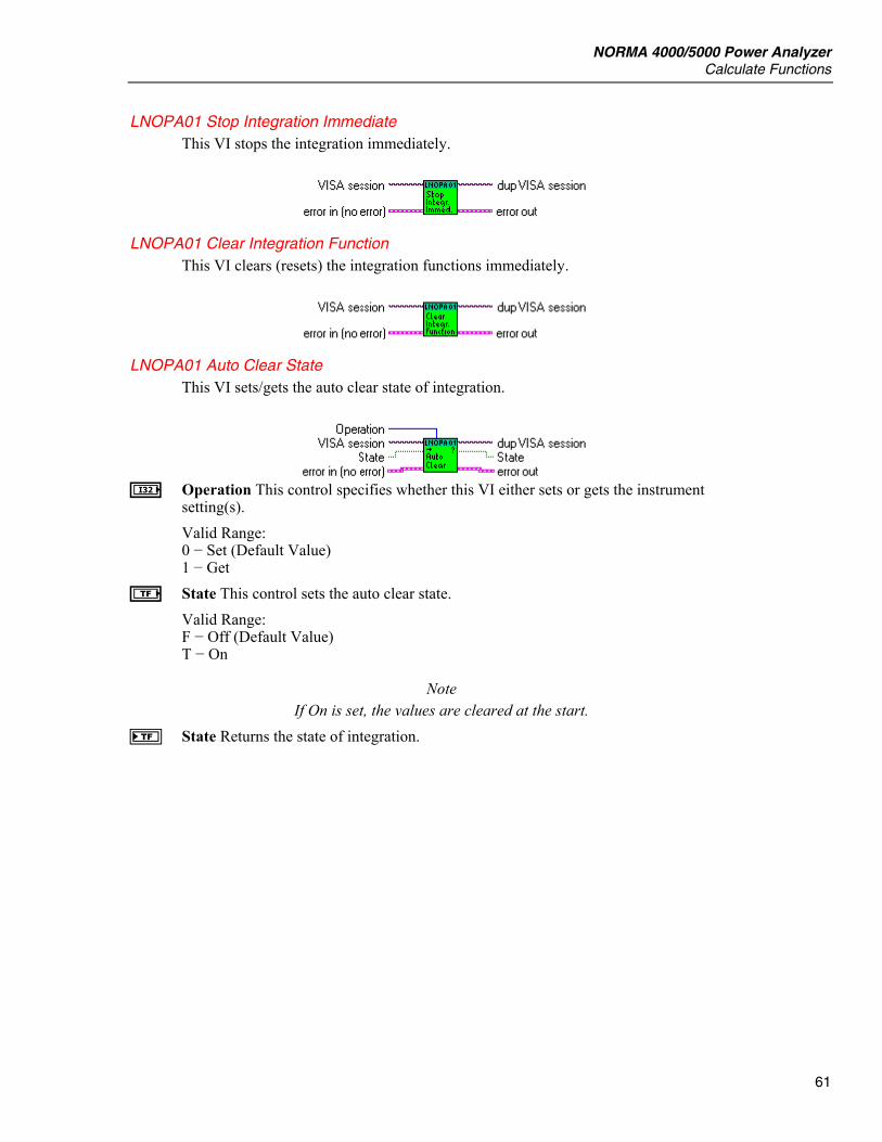
NORMA 4000/5000 Power Analyzer Calculate Functions
61
LNOPA01 Stop Integration Immediate This VI stops the integration immediately.
LNOPA01 Clear Integration Function This VI clears (resets) the integration functions immediately.
LNOPA01 Auto Clear State This VI sets/gets the auto clear state of integration.
I Operation This control specifies whether this VI either sets or gets the instrument
setting(s). Valid Range: 0 − Set (Default Value) 1 − Get
e State This control sets the auto clear state. Valid Range: F − Off (Default Value) T − On
Note If On is set, the values are cleared at the start.
f State Returns the state of integration.

LabVIEW Driver Reference Manual
62
Memory Record
LNOPA01 Configure Memory This VI configures the memory recording.
Note (1) All input arrays to this function must be of the same size. (2) This VI sets the Record Length and Pretrigger Length to 0.0 first to prevent Instrument Error. Then the parameter values will be set.
e State This control sets the state of given sweep.
Valid Range: F − Off (Default Value) T − On
I Sweep This control sets the type of sweep. Valid Range: 0 − Realtime (Default Value)
Note Average will be used in future.
I Count This control sets the count of given sweep. Valid Range: 0 to 1000 Default Value: 1
E Pretrigger Length This control sets the pretrigger length in second. Valid Range: 0.0 to MEM_RECORD_MAX Default Value: 0.0
E Record Length This control sets the record length in second. Valid Range: 0.0 to MEM_RECORD_MAX Default Value: 100.0
NORMA 4000/5000 Power Analyzer Memory Record
63
Note This record length includes pretrigger length.
I Factor Sets the sample factor. Valid Range: 1 to 65535 Default Value: 1
Note The value has to be smaller then record length (setRecordLength) and pretrigger record length (setPretriggerLength).
L Function This control specifies the array of measurement functions. Each element in the passed array should represent one measurement function. Valid Range for Sweep Realtime: 0 − True RMS Voltage 15 − True RMS Current 28 − Active Power 51 − Shaft torque [Nm] 52 − Rotational speed [rpm] 53 − Mechanical power [W] Valid Range for Sweep Average: 0 − Voltage True RMS (True RMS Voltage) 1 − Voltage Mean (Mean value of Voltage) 2 − Voltage Rectified Mean (Rectified Mean Voltage) 3 − Voltage Peak-To-Peak (Peak-to-peak Voltage) 4 − Voltage Highest Value (Highest value within averaging interval) 5 − Voltage Lowest Value (Lowest value within averaging interval) 6 − Voltage Crest Factor (Voltage Crest Factor) 7 − Voltage Absolute Phase (Voltage Absolute Phase) 8 − Voltage True RMS Phase-To-Phase (True RMS phase-to-phase Voltage) 9 − Voltage Harmonic 10 − Voltage TRMS Phase-To-Phase Harmonic 11 − Voltage Form Factor 12 − Voltage Harmonic Content 13 − Voltage Fundamental Content 14 − Voltage THD 15 − Current True RMS (True RMS Current) 16 − Current Mean (Mean value of Current) 17 − Current Rectified Mean (Rectified Mean Current) 18 − -Current Peak-To-Peak (Peak-to-peak Current) 19 − Current Highest Value (Highest value within averaging interval) 20 − Current Lowest Value (Lowest value within averaging interval) 21 − Current Crest Factor 22 − Current Absolute Phase (Current Absolute Phase) 23 − Current Harmonic 24 − Current Form Factor 25 − Current Harmonic Content 26 − Current Fundamental Content 27 − Current THD 28 − Power Active (Active Power) 29 − Power Apparent (Apparent Power)

LabVIEW Driver Reference Manual
64
30 − Power Reactive (Reactive Power) 31 − Power Factor (Power Factor) 32 − Power Active Harmonic 33 − Power Apparent Harmonic 34 − Power Reactive Harmonic 35 − Power Factor Harmonic 36 − Power Corrected (Corrected Power) 37 − Phase 38 − Phase Harmonic 39 − Impedance 40 − Resistance Serial 41 − Resistance Parallel 42 − Reactance Serial 43 − Reactance Parallel 44 − Impedance Harmonic 45 − Resistance Serial Harmonic 46 − Resistance Parallel Harmonic 47 − Reactance Serial Harmonic 48 − Reactance Parallel Harmonic 49 − Frequency 50 − Averaging Interval 51 − Shaft Torque [Nm] 52 − Rotational Speed [rpm] 53 − Mechanical Power [W] 54 − Rotational Asynchronousity [%] 55 − Motor Efficiency [%] 56 − Raw Process Input Value [V/Hz] 57 − Voltage Mean Phase-To-Phase 58 − Voltage Rectified Mean Phase-To-Phase 59 − Voltage Form Factor Phase-To-Phase 60 − Averaging Interval Relative Timestamp 61 − Electrical Efficiency 62 − Electrical Efficiency Harmonic 63 − True RMS Voltage Without DC 64 − True RMS Current Without DC 65 − Voltage THD Phase-To-Phase 66 − Voltage Harmonic Content Phase-To-Phase 67 − Voltage Fundamental Content Phase-To-Phase
Note Values 51 to 56 are available only with option Process Interface.
L Phase This control specifies the array of phase numbers. Valid Range: For Measurement: 0 − Voltage True RMS (True RMS Voltage) 1 − Voltage Mean (Mean value of Voltage) 2 − Voltage Rectified Mean (Rectified Mean Voltage) 3 − Voltage Peak-To-Peak (Peak-to-peak Voltage) 4 − Voltage Highest Value (Highest value within averaging interval) 5 − Voltage Lowest Value (Lowest value within averaging interval) 6 − Voltage Crest Factor (Voltage Crest Factor) 7 − Voltage Absolute Phase (Voltage Absolute Phase) 9 − Voltage Harmonic

NORMA 4000/5000 Power Analyzer Memory Record
65
15 − Current True RMS (True RMS Current) 16 − Current Mean (Mean value of Current) 17 − Current Rectified Mean (Rectified Mean Current) 18 − Current Peak-To-Peak (Peak-to-peak Current) 19 − Current Highest Value (Highest value within averaging interval) 20 − Current Lowest Value (Lowest value within averaging interval) 21 − Current Crest Factor 22 − Current Absolute Phase (Current Absolute Phase) 23 − Current Harmonic 28 − Power Active (Active Power) 29 − Power Apparent (Apparent Power) 30 − Power Reactive (Reactive Power) 31 − Power Factor (Power Factor) 32 − Power Active Harmonic 33 − Power Apparent Harmonic 34 − Power Reactive Harmonic 35 − Power Factor Harmonic 36 − Power Corrected (Corrected Power) 37 − Phase 38 − Phase Harmonic 39 − Impedance 40 − Resistance Serial 41 − Resistance Parallel 42 − Reactance Serial 43 − Reactance Parallel 44 − Impedance Harmonic 45 − Resistance Serial Harmonic 46 − Resistance Parallel Harmonic 47 − Reactance Serial Harmonic 48 − Reactance Parallel Harmonic 63 − True RMS Voltage Without DC 64 − True RMS Current Without DC are Valid Values -1: Sum of 1st 3-phase system (phase 1 … phase 3) 460: Sum of 2nd 3-phase system (phase 4 … phase 6) 1 to 3: for three channel model 1 to 6: for six channel model For Measurement: 11 − Voltage Form Factor 12 − Voltage Harmonic Content 13 − Voltage Fundamental Content 14 − Voltage THD 24 − Current Form Factor 25 − Current Harmonic Content 26 − Current Fundamental Content 27 − Current THD are Valid Values: 1 to 3: for three channel model 1 to 6: for six channel model For Measurement: 8 − Voltage True RMS Phase-To-Phase (True RMS phase-to-phase Voltage) 10 − Voltage TRMS Phase-To-Phase Harmonic 57 − Voltage Mean Phase-To-Phase
LabVIEW Driver Reference Manual
66
58 − Voltage Rectified Mean Phase-To-Phase 59 − Voltage Form Factor Phase-To-Phase are Valid Values: 12, 23, 31,123: for three channel model 12, 23, 31, 45, 56, 64, 123, 456: for six channel model For Measurement: 49 − Frequency 50 − Averaging Interval 60 − Averaging Interval Relative Timestamp is valid -1 only For Measurements: 51 − Shaft Torque [Nm] 52 − Rotational Speed [rpm] 53 − Mechanical Power [W] 54 − Rotational Asynchronousity [%] 55 − Motor Efficiency [%] are valid values: 1 to 4, the values are independent of number of phases For Measurement: 56 − Raw Process Input Value [V/Hz] are valid values: 1 to 8, the values are independent of number of phases For Measurements: 61 − Electrical Efficiency 62 − Electrical Efficiency Harmonic are Valid Values: -1: Sum of 1st 3-phase system (phase 1 … phase 3) 460: Sum of 2nd 3-phase system (phase 4 … phase 6) For Measurements: 65 − Voltage THD Phase-To-Phase 66 − Voltage Harmonic Content Phase-To-Phase 67 − Voltage Fundamental Content Phase-To-Phase are Valid Values: 12, 23, 31: for three channel model 12, 23, 31, 45, 56, 64: for six channel model
L Modifier This control specifies the array of modifiers of voltage measurement function.
Note Only None, Positive Integral and Negative Integral are available now.
Valid Range: For Measurement: 1 − Voltage Mean (Mean value of Voltage) 16 − Current Mean (Mean value of Current) 28 − Power Active (Active Power) 29 − Power Apparent (Apparent Power) 30 − Power Reactive (Reactive Power) 32 − Power Active Harmonic 33 − Power Apparent Harmonic 34 − Power Reactive Harmonic

NORMA 4000/5000 Power Analyzer Memory Record
67
are Valid Values 0 − None 1 − Minimum 2 − Maximum 3 − Integral Positive 4 − Integral Negative 5 − Integral For Measurement: 0 − Voltage True RMS (True RMS Voltage) 2 − Voltage Rectified Mean (Rectified Mean Voltage) 3 − Voltage Peak-To-Peak (Peak-to-peak Voltage) 4 − Voltage Highest Value (Highest value within averaging interval) 5 − Voltage Lowest Value (Lowest value within averaging interval) 6 − Voltage Crest Factor (Voltage Crest Factor) 7 − Voltage Absolute Phase (Voltage Absolute Phase) 8 − Voltage True RMS Phase-To-Phase (True RMS phase-to-phase Voltage) 9 − Voltage Harmonic 10 − Voltage TRMS Phase-To-Phase Harmonic 11 − Voltage Form Factor 12 − Voltage Harmonic Content 13 − Voltage Fundamental Content 14 − Voltage THD 15 − Current True RMS (True RMS Current) 17 − Current Rectified Mean (Rectified Mean Current) 18 − Current Peak-To-Peak (Peak-to-peak Current) 19 − Current Highest Value (Highest value within averaging interval) 20 − Current Lowest Value (Lowest value within averaging interval) 21 − Current Crest Factor 22 − Current Absolute Phase (Current Absolute Phase) 23 − Current Harmonic 24 − Current Form Factor 25 − Current Harmonic Content 26 − Current Fundamental Content 27 − Current THD 31 − Power Factor (Power Factor) 35 − Power Factor Harmonic 36 − Power Corrected (Corrected Power) 37 − Phase 38 − Phase Harmonic 39 − Impedance 40 − Resistance Serial 41 − Resistance Parallel 42 − Reactance Serial 43 − Reactance Parallel 44 − Impedance Harmonic 45 − Resistance Serial Harmonic 46 − Resistance Parallel Harmonic 47 − Reactance Serial Harmonic 48 − Reactance Parallel Harmonic 49 − Frequency 51 − Shaft Torque [Nm] 52 − Rotational Speed [rpm] 53 − Mechanical Power [W] 54 − Rotational Asynchronousity [%]
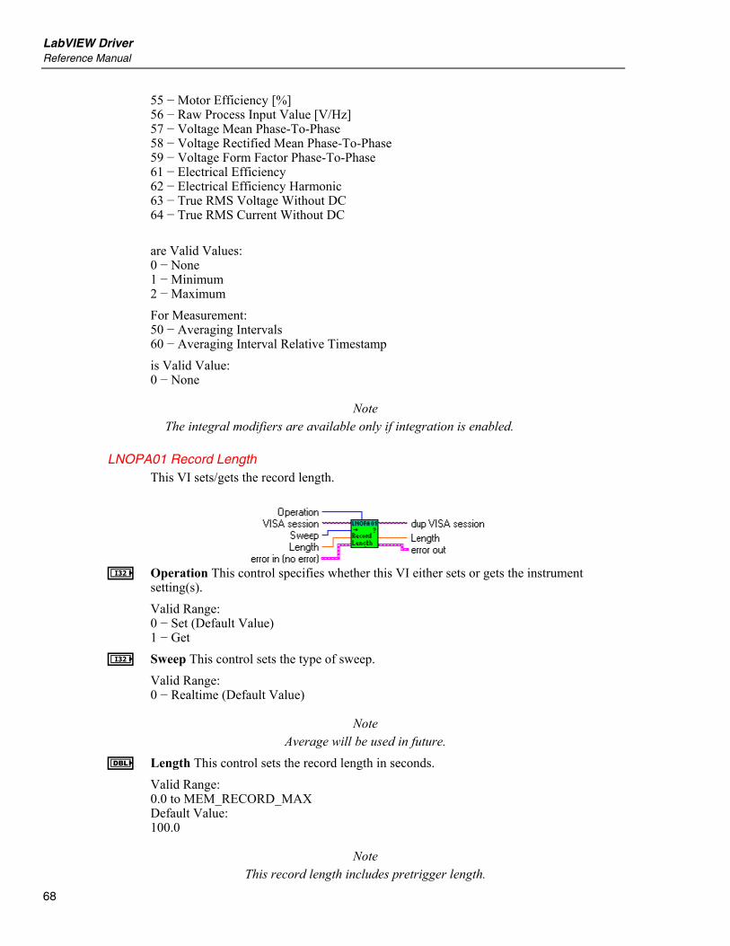
LabVIEW Driver Reference Manual
68
55 − Motor Efficiency [%] 56 − Raw Process Input Value [V/Hz] 57 − Voltage Mean Phase-To-Phase 58 − Voltage Rectified Mean Phase-To-Phase 59 − Voltage Form Factor Phase-To-Phase 61 − Electrical Efficiency 62 − Electrical Efficiency Harmonic 63 − True RMS Voltage Without DC 64 − True RMS Current Without DC are Valid Values: 0 − None 1 − Minimum 2 − Maximum For Measurement: 50 − Averaging Intervals 60 − Averaging Interval Relative Timestamp is Valid Value: 0 − None
Note The integral modifiers are available only if integration is enabled.
LNOPA01 Record Length This VI sets/gets the record length.
I Operation This control specifies whether this VI either sets or gets the instrument
setting(s). Valid Range: 0 − Set (Default Value) 1 − Get
I Sweep This control sets the type of sweep. Valid Range: 0 − Realtime (Default Value)
Note Average will be used in future.
E Length This control sets the record length in seconds. Valid Range: 0.0 to MEM_RECORD_MAX Default Value: 100.0
Note This record length includes pretrigger length.

NORMA 4000/5000 Power Analyzer Memory Record
69
F Length Returns the record length in seconds.
LNOPA01 Max Record Length This VI sets the record length to maximum. The whole free memory is used for data recording.
I Sweep This control sets the type of sweep.
Valid Range: 0 − Realtime (Default Value)
Note Average will be used in future.
LNOPA01 Pretrigger Length This VI sets/gets the pretrigger length.
I Operation This control specifies whether this VI either sets or gets the instrument
setting(s). Valid Range: 0 − Set (Default Value) 1 − Get
I Sweep This control sets the type of sweep. Valid Range: 0 − Realtime (Default Value)
Note Average will be used in future.
E Length This control sets the pretrigger length in seconds. Valid Range: 0.0 to MEM_RECORD_MAX Default Value: 0.0
F Length Returns the pretrigger length in seconds.
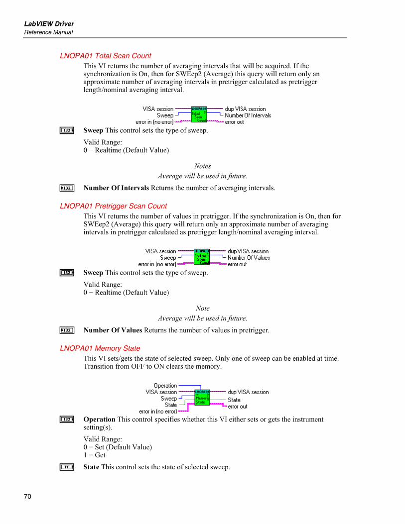
LabVIEW Driver Reference Manual
70
LNOPA01 Total Scan Count This VI returns the number of averaging intervals that will be acquired. If the synchronization is On, then for SWEep2 (Average) this query will return only an approximate number of averaging intervals in pretrigger calculated as pretrigger length/nominal averaging interval.
I Sweep This control sets the type of sweep.
Valid Range: 0 − Realtime (Default Value)
Notes Average will be used in future.
J Number Of Intervals Returns the number of averaging intervals.
LNOPA01 Pretrigger Scan Count This VI returns the number of values in pretrigger. If the synchronization is On, then for SWEep2 (Average) this query will return only an approximate number of averaging intervals in pretrigger calculated as pretrigger length/nominal averaging interval.
I Sweep This control sets the type of sweep.
Valid Range: 0 − Realtime (Default Value)
Note Average will be used in future.
J Number Of Values Returns the number of values in pretrigger.
LNOPA01 Memory State This VI sets/gets the state of selected sweep. Only one of sweep can be enabled at time. Transition from OFF to ON clears the memory.
I Operation This control specifies whether this VI either sets or gets the instrument
setting(s). Valid Range: 0 − Set (Default Value) 1 − Get
e State This control sets the state of selected sweep.
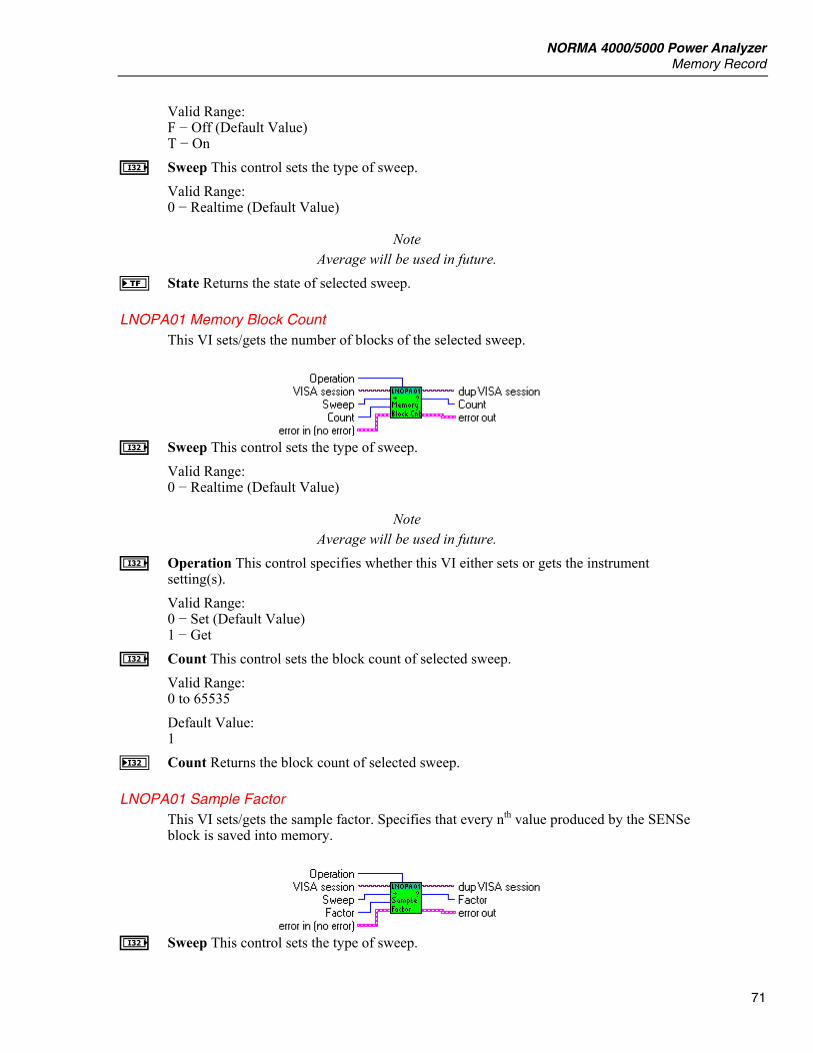
NORMA 4000/5000 Power Analyzer Memory Record
71
Valid Range: F − Off (Default Value) T − On
I Sweep This control sets the type of sweep. Valid Range: 0 − Realtime (Default Value)
Note Average will be used in future.
f State Returns the state of selected sweep.
LNOPA01 Memory Block Count This VI sets/gets the number of blocks of the selected sweep.
I Sweep This control sets the type of sweep.
Valid Range: 0 − Realtime (Default Value)
Note Average will be used in future.
I Operation This control specifies whether this VI either sets or gets the instrument setting(s). Valid Range: 0 − Set (Default Value) 1 − Get
I Count This control sets the block count of selected sweep. Valid Range: 0 to 65535 Default Value: 1
J Count Returns the block count of selected sweep.
LNOPA01 Sample Factor This VI sets/gets the sample factor. Specifies that every nth value produced by the SENSe block is saved into memory.
I Sweep This control sets the type of sweep.
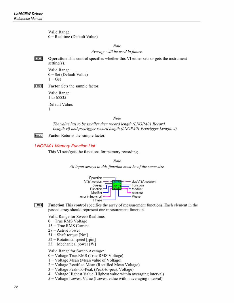
LabVIEW Driver Reference Manual
72
Valid Range: 0 − Realtime (Default Value)
Note Average will be used in future.
I Operation This control specifies whether this VI either sets or gets the instrument setting(s). Valid Range: 0 − Set (Default Value) 1 − Get
I Factor Sets the sample factor. Valid Range: 1 to 65535 Default Value: 1
Note The value has to be smaller then record length (LNOPA01 Record Length.vi) and pretrigger record length (LNOPA01 Pretrigger Length.vi).
J Factor Returns the sample factor.
LNOPA01 Memory Function List This VI sets/gets the functions for memory recording.
Note All input arrays to this function must be of the same size.
L Function This control specifies the array of measurement functions. Each element in the
passed array should represent one measurement function. Valid Range for Sweep Realtime: 0 − True RMS Voltage 15 − True RMS Current 28 − Active Power 51 − Shaft torque [Nm] 52 − Rotational speed [rpm] 53 − Mechanical power [W] Valid Range for Sweep Average: 0 − Voltage True RMS (True RMS Voltage) 1 − Voltage Mean (Mean value of Voltage) 2 − Voltage Rectified Mean (Rectified Mean Voltage) 3 − Voltage Peak-To-Peak (Peak-to-peak Voltage) 4 − Voltage Highest Value (Highest value within averaging interval) 5 − Voltage Lowest Value (Lowest value within averaging interval)
NORMA 4000/5000 Power Analyzer Memory Record
73
6 − Voltage Crest Factor (Voltage Crest Factor) 7 − Voltage Absolute Phase (Voltage Absolute Phase) 8 − Voltage True RMS Phase-To-Phase (True RMS phase-to-phase Voltage) 9 − Voltage Harmonic 10 − Voltage TRMS Phase-To-Phase Harmonic 11 − Voltage Form Factor 12 − Voltage Harmonic Content 13 − Voltage Fundamental Content 14 − Voltage THD 15 − Current True RMS (True RMS Current) 16 − Current Mean (Mean value of Current) 17 − Current Rectified Mean (Rectified Mean Current) 18 − Current Peak-To-Peak (Peak-to-peak Current) 19 − Current Highest Value (Highest value within averaging interval) 20 − Current Lowest Value (Lowest value within averaging interval) 21 − Current Crest Factor 22 − Current Absolute Phase (Current Absolute Phase) 23 − Current Harmonic 24 − Current Form Factor 25 − Current Harmonic Content 26 − Current Fundamental Content 27 − Current THD 28 − Power Active (Active Power) 29 − Power Apparent (Apparent Power) 30 − Power Reactive (Reactive Power) 31 − Power Factor (Power Factor) 32 − Power Active Harmonic 33 − Power Apparent Harmonic 34 − Power Reactive Harmonic 35 − Power Factor Harmonic 36 − Power Corrected (Corrected Power) 37 − Phase 38 − Phase Harmonic 39 − Impedance 40 − Resistance Serial 41 − Resistance Parallel 42 − Reactance Serial 43 − Reactance Parallel 44 − Impedance Harmonic 45 − Resistance Serial Harmonic 46 − Resistance Parallel Harmonic 47 − Reactance Serial Harmonic 48 − Reactance Parallel Harmonic 49 − Frequency 50 − Averaging Interval 51 − Shaft Torque [Nm] 52 − Rotational Speed [rpm] 53 − Mechanical Power [W] 54 − Rotational Asynchronousity [%] 55 − Motor Efficiency [%] 56 − Raw Process Input Value [V/Hz] 57 − Voltage Mean Phase-To-Phase 58 − Voltage Rectified Mean Phase-To-Phase 59 − Voltage Form Factor Phase-To-Phase 60 − Averaging Interval Relative Timestamp
LabVIEW Driver Reference Manual
74
61 − Electrical Efficiency 62 − Electrical Efficiency Harmonic 63 − True RMS Voltage Without DC 64 − True RMS Current Without DC 65 − Voltage THD Phase-To-Phase 66 − Voltage Harmonic Content Phase-To-Phase 67 − Voltage Fundamental Content Phase-To-Phase
Note Values 51 to 56 are available only with option Process Interface.
L Phase This control specifies the array of phase numbers. Valid Range: For Measurement: 0 − Voltage True RMS (True RMS Voltage) 1 − Voltage Mean (Mean value of Voltage) 2 − Voltage Rectified Mean (Rectified Mean Voltage) 3 − Voltage Peak-To-Peak (Peak-to-peak Voltage) 4 − Voltage Highest Value (Highest value within averaging interval) 5 − Voltage Lowest Value (Lowest value within averaging interval) 6 − Voltage Crest Factor (Voltage Crest Factor) 7 − Voltage Absolute Phase (Voltage Absolute Phase) 9 − Voltage Harmonic 15 − Current True RMS (True RMS Current) 16 − Current Mean (Mean value of Current) 17 − Current Rectified Mean (Rectified Mean Current) 18 − Current Peak-To-Peak (Peak-to-peak Current) 19 − Current Highest Value (Highest value within averaging interval) 20 − Current Lowest Value (Lowest value within averaging interval) 21 − Current Crest Factor 22 − Current Absolute Phase (Current Absolute Phase) 23 − Current Harmonic 28 − Power Active (Active Power) 29 − Power Apparent (Apparent Power) 30 − Power Reactive (Reactive Power) 31 − Power Factor (Power Factor) 32 − Power Active Harmonic 33 − Power Apparent Harmonic 34 − Power Reactive Harmonic 35 − Power Factor Harmonic 36 − Power Corrected (Corrected Power) 37 − Phase 38 − Phase Harmonic 39 − Impedance 40 − Resistance Serial 41 − Resistance Parallel 42 − Reactance Serial 43 − Reactance Parallel 44 − Impedance Harmonic 45 − Resistance Serial Harmonic 46 − Resistance Parallel Harmonic 47 − Reactance Serial Harmonic 48 − Reactance Parallel Harmonic

NORMA 4000/5000 Power Analyzer Memory Record
75
63 − True RMS Voltage Without DC 64 − True RMS Current Without DC are Valid Values -1 : Sum of 1st 3-phase system (phase 1 … phase 3) 460: Sum of 2nd 3-phase system (phase 4 … phase 6) 1 to 3: for three channel model 1 to 6: for six channel model For Measurement: 11 − Voltage Form Factor 12 − Voltage Harmonic Content 13 − Voltage Fundamental Content 14 − Voltage THD 24 − Current Form Factor 25 − Current Harmonic Content 26 − Current Fundamental Content 27 − Current THD are Valid Values: 1 to 3: for three channel model 1 to 6: for six channel model For Measurement: 8 − Voltage True RMS Phase-To-Phase (True RMS phase-to-phase Voltage) 10 − Voltage TRMS Phase-To-Phase Harmonic 57 − Voltage Mean Phase-To-Phase 58 − Voltage Rectified Mean Phase-To-Phase 59 − Voltage Form Factor Phase-To-Phase are Valid Values: 12, 23, 31, 123: for three channel model 12, 23, 31, 45, 56, 64, 123, 456: for six channel model For Measurement: 49 − Frequency 50 − Averaging Interval 60 − Averaging Interval Relative Timestamp is valid -1 only For Measurements: 51 − Shaft Torque [Nm] 52 − Rotational Speed [rpm] 53 − Mechanical Power [W] 54 − Rotational Asynchronousity [%] 55 − Motor Efficiency [%] are valid values: 1 to 4, the values are independent of number of phases For Measurement: 56 − Raw Process Input Value [V/Hz] are valid values: 1 to 8, the values are independent of number of phases For Measurements: 61 − Electrical Efficiency 62 − Electrical Efficiency Harmonic

LabVIEW Driver Reference Manual
76
are Valid Values: -1 : Sum of 1st 3-phase system (phase 1 … phase 3) 460: Sum of 2nd 3-phase system (phase 4 … phase 6) For Measurements: 65 − Voltage THD Phase-To-Phase 66 − Voltage Harmonic Content Phase-To-Phase 67 − Voltage Fundamental Content Phase-To-Phase are Valid Values: 12, 23, 31: for three channel model 12, 23, 31, 45, 56, 64: for six channel model
L Modifier This control specifies the array of modifiers of voltage measurement function.
Note Only None, Positive Integral and Negative Integral are available now.
Valid Range: For Measurement: 1 − Voltage Mean (Mean value of Voltage) 16 − Current Mean (Mean value of Current) 28 − Power Active (Active Power) 29 − Power Apparent (Apparent Power) 30 − Power Reactive (Reactive Power) 32 − Power Active Harmonic 33 − Power Apparent Harmonic 34 − Power Reactive Harmonic are Valid Values 0 − None 1 − Minimum 2 − Maximum 3 − Integral Positive 4 − Integral Negative 5 − Integral For Measurement: 0 − Voltage True RMS (True RMS Voltage) 2 − Voltage Rectified Mean (Rectified Mean Voltage) 3 − Voltage Peak-To-Peak (Peak-to-peak Voltage) 4 − Voltage Highest Value (Highest value within averaging interval) 5 − Voltage Lowest Value (Lowest value within averaging interval) 6 − Voltage Crest Factor (Voltage Crest Factor) 7 − Voltage Absolute Phase (Voltage Absolute Phase) 8 − Voltage True RMS Phase-To-Phase (True RMS phase-to-phase Voltage) 9 − Voltage Harmonic 10 − Voltage TRMS Phase-To-Phase Harmonic 11 − Voltage Form Factor 12 − Voltage Harmonic Content 13 − Voltage Fundamental Content 14 − Voltage THD 15 − Current True RMS (True RMS Current) 17 − Current Rectified Mean (Rectified Mean Current) 18 − Current Peak-To-Peak (Peak-to-peak Current) 19 − Current Highest Value (Highest value within averaging interval) 20 − Current Lowest Value (Lowest value within averaging interval)

NORMA 4000/5000 Power Analyzer Memory Record
77
21 − Current Crest Factor 22 − Current Absolute Phase (Current Absolute Phase) 23 − Current Harmonic 24 − Current Form Factor 25 − Current Harmonic Content 26 − Current Fundamental Content 27 − Current THD 31 − Power Factor (Power Factor) 35 − Power Factor Harmonic 36 − Power Corrected (Corrected Power) 37 − Phase 38 − Phase Harmonic 39 − Impedance 40 − Resistance Serial 41 − Resistance Parallel 42 − Reactance Serial 43 − Reactance Parallel 44 − Impedance Harmonic 45 − Resistance Serial Harmonic 46 − Resistance Parallel Harmonic 47 − Reactance Serial Harmonic 48 − Reactance Parallel Harmonic 49 − Frequency 51 − Shaft Torque [Nm] 52 − Rotational Speed [rpm] 53 − Mechanical Power [W] 54 − Rotational Asynchronousity [%] 55 − Motor Efficiency [%] 56 − Raw Process Input Value [V/Hz] 57 − Voltage Mean Phase-To-Phase 58 − Voltage Rectified Mean Phase-To-Phase 59 − Voltage Form Factor Phase-To-Phase 61 − Electrical Efficiency 62 − Electrical Efficiency Harmonic 63 − True RMS Voltage Without DC 64 − True RMS Current Without DC 65 − Voltage THD Phase-To-Phase 66 − Voltage Harmonic Content Phase-To-Phase 67 − Voltage Fundamental Content Phase-To-Phase are Valid Values: 0 − None 1 − Minimum 2 − Maximum For Measurement: 50 − Averaging Intervals 60 − Averaging Interval Relative Timestamp is Valid Value: 0 − None
Note The integral modifiers are available only if integration is enabled.

LabVIEW Driver Reference Manual
78
I Operation This control specifies whether this VI either sets or gets the instrument setting(s). Valid Range: 0 − Set (Default Value) 1 − Get
I Sweep This control sets the type of sweep. Valid Range: 0 − Realtime (Default Value)
Note Average will be used in future.
K Function Returns the array of memory functions. K Phase Returns the array of phase numbers. K Modifier Returns the array of modifiers.
LNOPA01 Delete Memory This VI deletes all memory.
Spectrum
LNOPA01 Configure Spectrum This VI configures the spectrum measurement.
I Mode This control sets the harmonics calculation method.
Valid Range: 0 − FFT (Default Value) 1 − DFT
E Start Frequency This control sets the start frequency of the harmonics calculation. Valid Range: 0.0 (Default Value)
Note This function will accept only 0. Implemented only for compatibility reasons.
E Stop Frequency This control sets the stop frequency of the harmonics calculation. Valid Range: 10.0 to sample rate/2

NORMA 4000/5000 Power Analyzer Spectrum
79
Default Value: 10.0
L Function This control specifies the array of measurement functions for spectrum calculation. Each element in the passed array should represent one measurement function. Valid Range: 0 − True RMS Voltage 15 − True RMS Current 28 − Active Power
Note Only sampled values can be a part of the list.
L Phase This control specifies the array of phases. Valid Range: for 6 channel model: 1 to 3 for 12 channel model: 1 to 6 -1: Sum of all phases
LNOPA01 Initiate Spectrum This VI initiates a single frequency transform measurement.
Note The SENS:SWE1:STAT (Set Sweep State -memory storage samples) have to be OFF, otherwise the error -221, Settings conflict, will be generated.
LNOPA01 Spectrum Function List This VI sets/gets the frequency function list. Only sampled values can be a part of this list.
Note All input arrays to this function must be of the same size.
L Function This control specifies the array of measurement functions for spectrum
calculation. Each element in the passed array should represent one measurement function. Valid Range: 0 − True RMS Voltage 15 − True RMS Current 28 − Active Power
Note Only sampled values can be a part of the list.
L Phase This control specifies the array of phases.
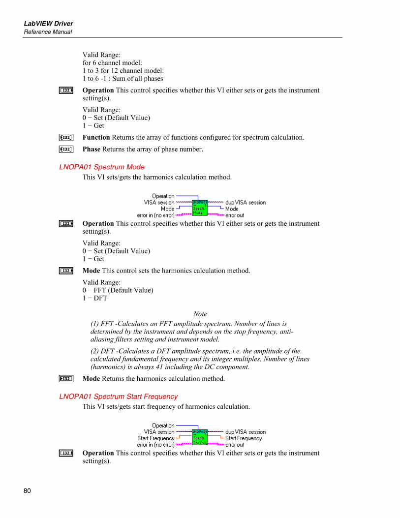
LabVIEW Driver Reference Manual
80
Valid Range: for 6 channel model: 1 to 3 for 12 channel model: 1 to 6 -1 : Sum of all phases
I Operation This control specifies whether this VI either sets or gets the instrument setting(s). Valid Range: 0 − Set (Default Value) 1 − Get
K Function Returns the array of functions configured for spectrum calculation. K Phase Returns the array of phase number.
LNOPA01 Spectrum Mode This VI sets/gets the harmonics calculation method.
I Operation This control specifies whether this VI either sets or gets the instrument
setting(s). Valid Range: 0 − Set (Default Value) 1 − Get
I Mode This control sets the harmonics calculation method. Valid Range: 0 − FFT (Default Value) 1 − DFT
Note (1) FFT -Calculates an FFT amplitude spectrum. Number of lines is determined by the instrument and depends on the stop frequency, anti-aliasing filters setting and instrument model. (2) DFT -Calculates a DFT amplitude spectrum, i.e. the amplitude of the calculated fundamental frequency and its integer multiples. Number of lines (harmonics) is always 41 including the DC component.
J Mode Returns the harmonics calculation method.
LNOPA01 Spectrum Start Frequency This VI sets/gets start frequency of harmonics calculation.
I Operation This control specifies whether this VI either sets or gets the instrument
setting(s).

NORMA 4000/5000 Power Analyzer Spectrum
81
Valid Range: 0 − Set (Default Value) 1 − Get
E Start Frequency This control sets the start frequency of the harmonics calculation. Valid Range: 0.0 (Default Value)
Note This function will accept only 0. Implemented only for compatibility reasons.
F Start Frequency Returns the start frequency of harmonics calculation.
Note This function will return only 0. Implemented only for compatibility reasons.
LNOPA01 Spectrum Stop Frequency This VI sets/getsstop frequency of the harmonics calculation.
I Operation This control specifies whether this VI either sets or gets the instrument
setting(s). Valid Range: 0 − Set (Default Value) 1 − Get
E Stop Frequency This control sets the upper frequency of the harmonics calculation (frequency of the rightmost FFT or DFT spectrum line). Valid Range: 10.0 to sample rate/2 Default Value: 10.0
F Stop Frequency Returns the upper frequency of the harmonics calculation.
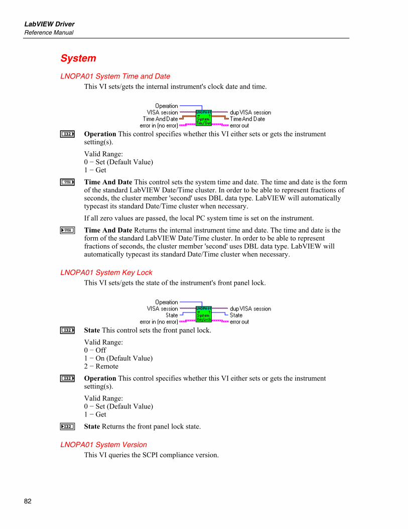
LabVIEW Driver Reference Manual
82
System
LNOPA01 System Time and Date This VI sets/gets the internal instrument's clock date and time.
I Operation This control specifies whether this VI either sets or gets the instrument
setting(s). Valid Range: 0 − Set (Default Value) 1 − Get
a Time And Date This control sets the system time and date. The time and date is the form of the standard LabVIEW Date/Time cluster. In order to be able to represent fractions of seconds, the cluster member 'second' uses DBL data type. LabVIEW will automatically typecast its standard Date/Time cluster when necessary. If all zero values are passed, the local PC system time is set on the instrument.
b Time And Date Returns the internal instrument time and date. The time and date is the form of the standard LabVIEW Date/Time cluster. In order to be able to represent fractions of seconds, the cluster member 'second' uses DBL data type. LabVIEW will automatically typecast its standard Date/Time cluster when necessary.
LNOPA01 System Key Lock This VI sets/gets the state of the instrument's front panel lock.
I State This control sets the front panel lock.
Valid Range: 0 − Off 1 − On (Default Value) 2 − Remote
I Operation This control specifies whether this VI either sets or gets the instrument setting(s). Valid Range: 0 − Set (Default Value) 1 − Get
J State Returns the front panel lock state.
LNOPA01 System Version This VI queries the SCPI compliance version.

NORMA 4000/5000 Power Analyzer System
83
Version Returns the SCPI compliance version.
LNOPA01 System Baud Rate This VI sets/gets the RS-232 communication baud rate.
I Baud Rate This control sets the RS-232 communication baud rate on the instrument.
Valid Values: 1200, 2400, 4800, 9600, 19200, 38400, 57600, 115200 baud Default Value: 115200 baud
I Operation This control specifies whether this VI either sets or gets the instrument setting(s). Valid Range: 0 − Set (Default Value) 1 − Get
J Baud Rate Returns the RS-232 baud rate the instrument uses.
LNOPA01 Display State This VI sets/gets the state of the instrument's main window.
e State This control sets the state of instrument's main window.
Valid Values: F − Off (Default Value) T − On
I Operation This control specifies whether this VI either sets or gets the instrument setting(s). Valid Range: 0 − Set (Default Value) 1 − Get
f State Returns the state of instrument's main window.
LNOPA01 System Key This VI simulates/returns the pressing of given key on the front panel keyboard.
I Key This control sets the simulated key.
LabVIEW Driver Reference Manual
84
Valid Range: 0 − None 1 − Enter (Default Value) 2 − Esc 3 − Up 4 − Down 5 − Left 6 − Right 7 − Sum 8 − PHA 9 − Wav 10 − Num 11 − Rec 12 − DSO 13 − VEC 14 − HAM 15 − Prn 16 − Mem 17 − Hold 18 − F1 19 − F2 20 − F3 21 − F4 22 − F5 23 − F6
Note 0 -None : No key is sent to the instrument.
I Operation This control specifies whether this VI either sets or gets the instrument setting(s). Valid Range: 0 − Set (Default Value) 1 − Get
J Key Returns the pressed key. Returned Values: 0 − None 1 − Enter 2 − Esc 3 − Up 4 − Down 5 − Left 6 − Right 7 − Sum 8 − PHA 9 − Wav 10 − Num 11 − Rec 12 − DSO 13 − VEC 14 − HAM 15 − Prn 16 − Mem
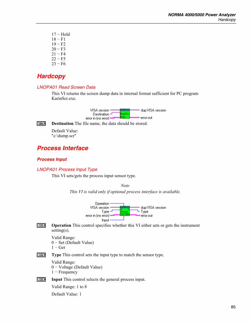
NORMA 4000/5000 Power Analyzer Hardcopy
85
17 − Hold 18 − F1 19 − F2 20 − F3 21 − F4 22 − F5 23 − F6
Hardcopy
LNOPA01 Read Screen Data This VI returns the screen dump data in internal format sufficient for PC program KarinScr.exe.
A Destination The file name, the data should be stored.
Default Value: "c:\dump.scr"
Process Interface
Process Input
LNOPA01 Process Input Type This VI sets/gets the process input sensor type.
Note This VI is valid only if optional process interface is available.
I Operation This control specifies whether this VI either sets or gets the instrument
setting(s). Valid Range: 0 − Set (Default Value) 1 − Get
I Type This control sets the input type to match the sensor type. Valid Range: 0 − Voltage (Default Value) 1 − Frequency
I Input This control selects the general process input. Valid Range: 1 to 8 Default Value: 1
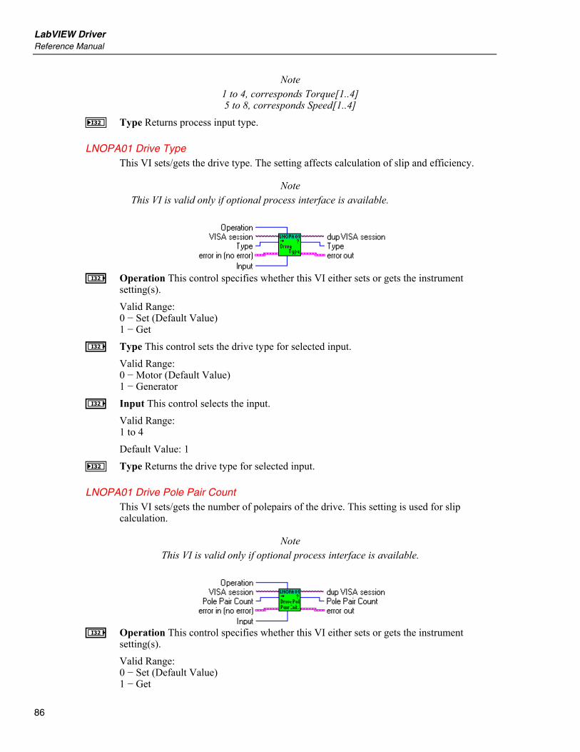
LabVIEW Driver Reference Manual
86
Note 1 to 4, corresponds Torque[1..4] 5 to 8, corresponds Speed[1..4]
J Type Returns process input type.
LNOPA01 Drive Type This VI sets/gets the drive type. The setting affects calculation of slip and efficiency.
Note This VI is valid only if optional process interface is available.
I Operation This control specifies whether this VI either sets or gets the instrument
setting(s). Valid Range: 0 − Set (Default Value) 1 − Get
I Type This control sets the drive type for selected input. Valid Range: 0 − Motor (Default Value) 1 − Generator
I Input This control selects the input. Valid Range: 1 to 4 Default Value: 1
J Type Returns the drive type for selected input.
LNOPA01 Drive Pole Pair Count This VI sets/gets the number of polepairs of the drive. This setting is used for slip calculation.
Note This VI is valid only if optional process interface is available.
I Operation This control specifies whether this VI either sets or gets the instrument
setting(s). Valid Range: 0 − Set (Default Value) 1 − Get
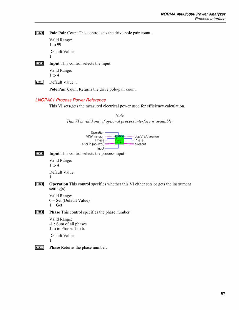
NORMA 4000/5000 Power Analyzer Process Interface
87
I Pole Pair Count This control sets the drive pole pair count. Valid Range: 1 to 99 Default Value: 1
I Input This control selects the input. Valid Range: 1 to 4
J Default Value: 1 Pole Pair Count Returns the drive pole-pair count.
LNOPA01 Process Power Reference This VI sets/gets the measured electrical power used for efficiency calculation.
Note This VI is valid only if optional process interface is available.
I Input This control selects the process input.
Valid Range: 1 to 4 Default Value: 1
I Operation This control specifies whether this VI either sets or gets the instrument setting(s). Valid Range: 0 − Set (Default Value) 1 − Get
I Phase This control specifies the phase number. Valid Range: -1 : Sum of all phases 1 to 6: Phases 1 to 6. Default Value: 1
J Phase Returns the phase number.

LabVIEW Driver Reference Manual
88
LNOPA01 Configure Torque This VI configures the torque input.
Note This VI is valid only if optional process interface is available.
I Input This control selects the torque input.
Valid Range: 1 to 4 Default Value: 1
E Scale Factor Sets the scaling factor. Valid Range: -1.0E+6 to 1.0E+6 Default Value: 1.0 [Nm/V]
E Offset Sets the offset. Valid Range: -1.0E+6 to 1.0E+6 Default Value: 0.0 V
I Input Type This control sets the shunt type for specified current input. Valid Range: 0 − Internal (Default Value) 1 − External
LNOPA01 Torque Scale Factor This VI sets/gets the torque scaling factor for the input that reflects conversion ratio of torque sensors employed. The difference between the value on the respective input and the specified offset is multiplied by this scaling factor before any further processing.
Note This VI is valid only if optional process interface is available.
I Operation This control specifies whether this VI either sets or gets the instrument
setting(s).
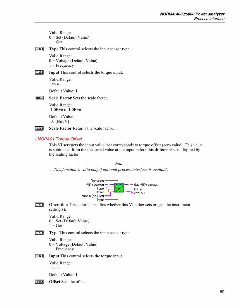
NORMA 4000/5000 Power Analyzer Process Interface
89
Valid Range: 0 − Set (Default Value) 1 − Get
I Type This control selects the input sensor type. Valid Range: 0 − Voltage (Default Value) 1 − Frequency
I Input This control selects the torque input. Valid Range: 1 to 4 Default Value: 1
F Scale Factor Sets the scale factor. Valid Range: -1.0E+6 to 1.0E+6 Default Value: 1.0 [Nm/V]
E Scale Factor Returns the scale factor.
LNOPA01 Torque Offset This VI sets/gets the input value that corresponds to torque offset (zero value). This value is subtracted from the measured value at the input before this difference is multiplied by the scaling factor.
Note This function is valid only if optional process interface is available.
I Operation This control specifies whether this VI either sets or gets the instrument
setting(s). Valid Range: 0 − Set (Default Value) 1 − Get
I Type This control selects the input sensor type. Valid Range: 0 − Voltage (Default Value) 1 − Frequency
I Input This control selects the torque input. Valid Range: 1 to 4 Default Value: 1
E Offset Sets the offset.
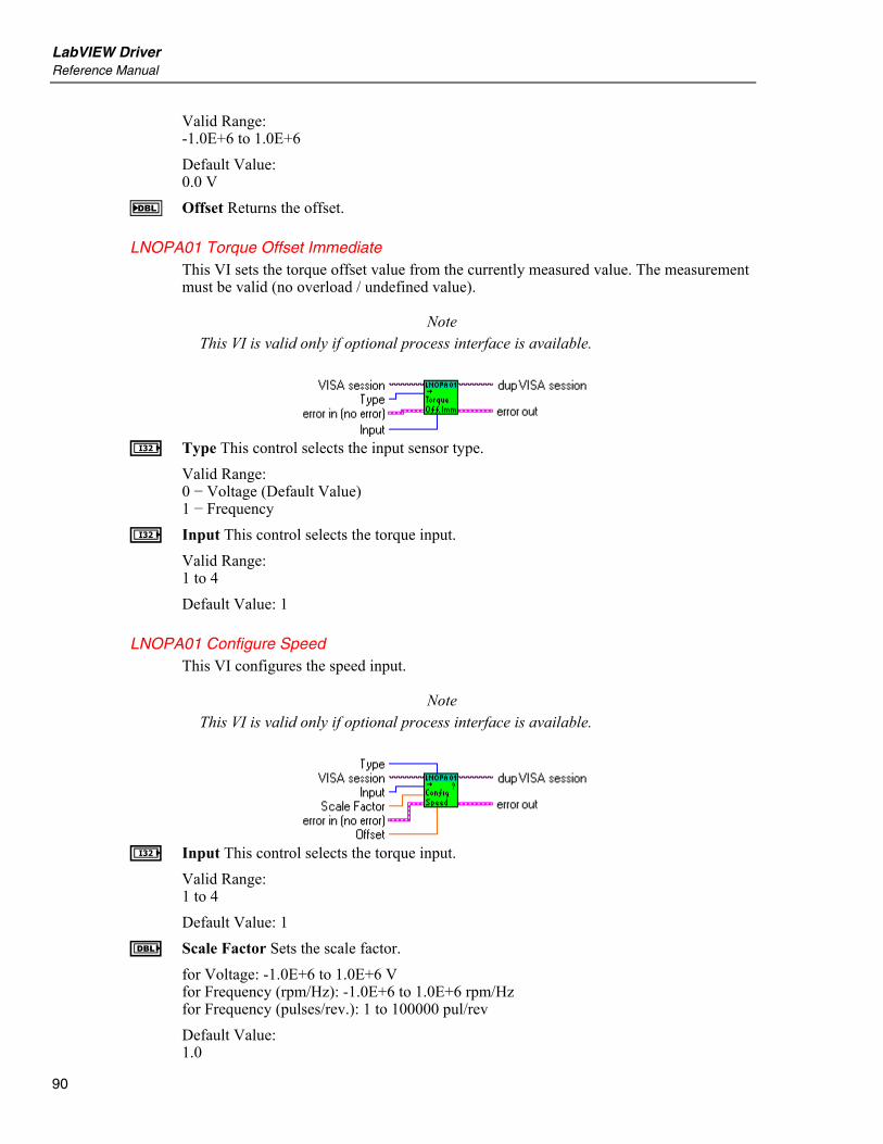
LabVIEW Driver Reference Manual
90
Valid Range: -1.0E+6 to 1.0E+6 Default Value: 0.0 V
F Offset Returns the offset.
LNOPA01 Torque Offset Immediate This VI sets the torque offset value from the currently measured value. The measurement must be valid (no overload / undefined value).
Note This VI is valid only if optional process interface is available.
I Type This control selects the input sensor type.
Valid Range: 0 − Voltage (Default Value) 1 − Frequency
I Input This control selects the torque input. Valid Range: 1 to 4 Default Value: 1
LNOPA01 Configure Speed This VI configures the speed input.
Note This VI is valid only if optional process interface is available.
I Input This control selects the torque input.
Valid Range: 1 to 4 Default Value: 1
E Scale Factor Sets the scale factor. for Voltage: -1.0E+6 to 1.0E+6 V for Frequency (rpm/Hz): -1.0E+6 to 1.0E+6 rpm/Hz for Frequency (pulses/rev.): 1 to 100000 pul/rev Default Value: 1.0
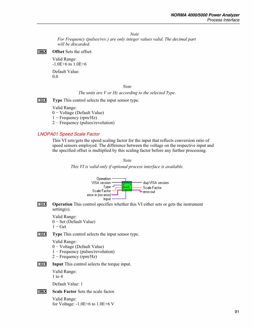
NORMA 4000/5000 Power Analyzer Process Interface
91
Note For Frequency (pulses/rev.) are only integer values valid. The decimal part will be discarded.
E Offset Sets the offset. Valid Range: -1.0E+6 to 1.0E+6 Default Value: 0.0
Note The units are V or Hz according to the selected Type.
I Type This control selects the input sensor type. Valid Range: 0 − Voltage (Default Value) 1 − Frequency (rpm/Hz) 2 − Frequency (pulses/revolution)
LNOPA01 Speed Scale Factor This VI sets/gets the speed scaling factor for the input that reflects conversion ratio of speed sensors employed. The difference between the voltage on the respective input and the specified offset is multiplied by this scaling factor before any further processing.
Note This VI is valid only if optional process interface is available.
I Operation This control specifies whether this VI either sets or gets the instrument
setting(s). Valid Range: 0 − Set (Default Value) 1 − Get
I Type This control selects the input sensor type. Valid Range: 0 − Voltage (Default Value) 1 − Frequency (pulses/revolution) 2 − Frequency (rpm/Hz)
I Input This control selects the torque input. Valid Range: 1 to 4 Default Value: 1
E Scale Factor Sets the scale factor. Valid Range: for Voltage: -1.0E+6 to 1.0E+6 V
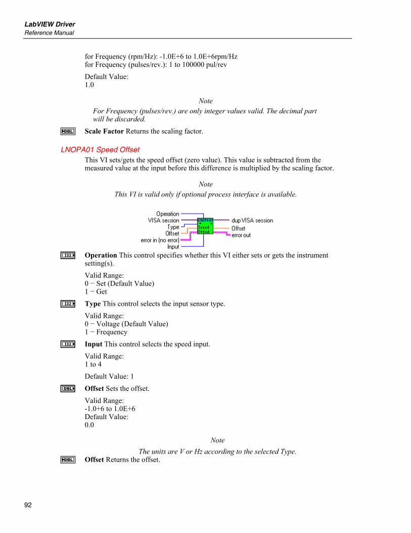
LabVIEW Driver Reference Manual
92
for Frequency (rpm/Hz): -1.0E+6 to 1.0E+6rpm/Hz for Frequency (pulses/rev.): 1 to 100000 pul/rev Default Value: 1.0
Note For Frequency (pulses/rev.) are only integer values valid. The decimal part will be discarded.
F Scale Factor Returns the scaling factor.
LNOPA01 Speed Offset This VI sets/gets the speed offset (zero value). This value is subtracted from the measured value at the input before this difference is multiplied by the scaling factor.
Note This VI is valid only if optional process interface is available.
I Operation This control specifies whether this VI either sets or gets the instrument
setting(s). Valid Range: 0 − Set (Default Value) 1 − Get
I Type This control selects the input sensor type. Valid Range: 0 − Voltage (Default Value) 1 − Frequency
I Input This control selects the speed input. Valid Range: 1 to 4 Default Value: 1
E Offset Sets the offset. Valid Range: -1.0+6 to 1.0E+6 Default Value: 0.0
Note The units are V or Hz according to the selected Type.
F Offset Returns the offset.

NORMA 4000/5000 Power Analyzer Process Interface
93
LNOPA01 Speed Offset Immediate This VI sets the speed offset value from the currently measured value. The measurement must be valid (no overload).
Note This VI is valid only if optional process interface is available.
I Type This control selects the input sensor type.
Valid Range: 0 − Voltage (Default Value) 1 − Frequency
I Input This control selects the speed input. Valid Range: 1 to 4 Default Value: 1
Process Output
LNOPA01 Configure Fixed Output This VI configures the fixed process output.
Note
This VI is valid only if optional process interface is available.
E Voltage This control sets the process output voltage.
Valid Range: -10.3 to 10.3 Default Value: 0.0
I Output This control selects the process output. Valid Range: 1 to 4 Default Value: 1
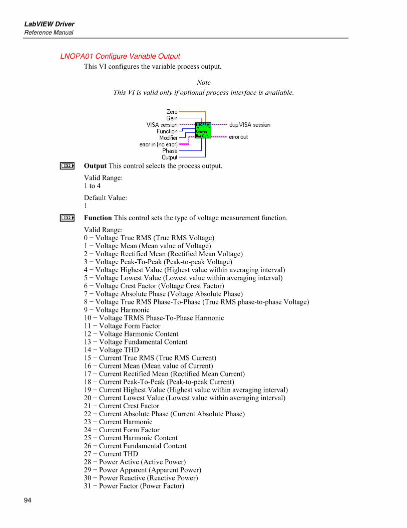
LabVIEW Driver Reference Manual
94
LNOPA01 Configure Variable Output This VI configures the variable process output.
Note This VI is valid only if optional process interface is available.
I Output This control selects the process output.
Valid Range: 1 to 4 Default Value: 1
I Function This control sets the type of voltage measurement function. Valid Range: 0 − Voltage True RMS (True RMS Voltage) 1 − Voltage Mean (Mean value of Voltage) 2 − Voltage Rectified Mean (Rectified Mean Voltage) 3 − Voltage Peak-To-Peak (Peak-to-peak Voltage) 4 − Voltage Highest Value (Highest value within averaging interval) 5 − Voltage Lowest Value (Lowest value within averaging interval) 6 − Voltage Crest Factor (Voltage Crest Factor) 7 − Voltage Absolute Phase (Voltage Absolute Phase) 8 − Voltage True RMS Phase-To-Phase (True RMS phase-to-phase Voltage) 9 − Voltage Harmonic 10 − Voltage TRMS Phase-To-Phase Harmonic 11 − Voltage Form Factor 12 − Voltage Harmonic Content 13 − Voltage Fundamental Content 14 − Voltage THD 15 − Current True RMS (True RMS Current) 16 − Current Mean (Mean value of Current) 17 − Current Rectified Mean (Rectified Mean Current) 18 − Current Peak-To-Peak (Peak-to-peak Current) 19 − Current Highest Value (Highest value within averaging interval) 20 − Current Lowest Value (Lowest value within averaging interval) 21 − Current Crest Factor 22 − Current Absolute Phase (Current Absolute Phase) 23 − Current Harmonic 24 − Current Form Factor 25 − Current Harmonic Content 26 − Current Fundamental Content 27 − Current THD 28 − Power Active (Active Power) 29 − Power Apparent (Apparent Power) 30 − Power Reactive (Reactive Power) 31 − Power Factor (Power Factor)
NORMA 4000/5000 Power Analyzer Process Interface
95
32 − Power Active Harmonic 33 − Power Apparent Harmonic 34 − Power Reactive Harmonic 35 − Power Factor Harmonic 36 − Power Corrected (Corrected Power) 37 − Phase 38 − Phase Harmonic 39 − Impedance 40 − Resistance Serial 41 − Resistance Parallel 42 − Reactance Serial 43 − Reactance Parallel 44 − Impedance Harmonic 45 − Resistance Serial Harmonic 46 − Resistance Parallel Harmonic 47 − Reactance Serial Harmonic 48 − Reactance Parallel Harmonic 49 − Frequency 50 − Averaging Interval 51 − Shaft Torque [Nm] 52 − Rotational Speed [rpm] 53 − Mechanical Power [W] 54 − Rotational Asynchronousity [%] 55 − Motor Efficiency [%] 56 − Raw Process Input Value [V/Hz] 57 − Voltage Mean Phase-To-Phase 58 − Voltage Rectified Mean Phase-To-Phase 59 − Voltage Form Factor Phase-To-Phase 60 − Averaging Interval Relative Timestamp 61 − Electrical Efficiency 62 − Electrical Efficiency Harmonic 63 − True RMS Voltage Without DC 64 − True RMS Current Without DC 65 − Voltage THD Phase-To-Phase 66 − Voltage Harmonic Content Phase-To-Phase 67 − Voltage Fundamental Content Phase-To-Phase
Note Values 51 to 56 are available only with option Process Interface.
I Phase This control specifies the phase number. Valid Range: For Measurement: 0 − Voltage True RMS (True RMS Voltage) 1 − Voltage Mean (Mean value of Voltage) 2 − Voltage Rectified Mean (Rectified Mean Voltage) 3 − Voltage Peak-To-Peak (Peak-to-peak Voltage) 4 − Voltage Highest Value (Highest value within averaging interval) 5 − Voltage Lowest Value (Lowest value within averaging interval) 6 − Voltage Crest Factor (Voltage Crest Factor) 7 − Voltage Absolute Phase (Voltage Absolute Phase) 9 − Voltage Harmonic 15 − Current True RMS (True RMS Current) 16 − Current Mean (Mean value of Current)

LabVIEW Driver Reference Manual
96
17 − Current Rectified Mean (Rectified Mean Current) 18 − Current Peak-To-Peak (Peak-to-peak Current) 19 − Current Highest Value (Highest value within averaging interval) 20 − Current Lowest Value (Lowest value within averaging interval) 21 − Current Crest Factor 22 − Current Absolute Phase (Current Absolute Phase) 23 − Current Harmonic 28 − Power Active (Active Power) 29 − Power Apparent (Apparent Power) 30 − Power Reactive (Reactive Power) 31 − Power Factor (Power Factor) 32 − Power Active Harmonic 33 − Power Apparent Harmonic 34 − Power Reactive Harmonic 35 − Power Factor Harmonic 36 − Power Corrected (Corrected Power) 37 − Phase 38 − Phase Harmonic 39 − Impedance 40 − Resistance Serial 41 − Resistance Parallel 42 − Reactance Serial 43 − Reactance Parallel 44 − Impedance Harmonic 45 − Resistance Serial Harmonic 46 − Resistance Parallel Harmonic 47 − Reactance Serial Harmonic 48 − Reactance Parallel Harmonic 63 − True RMS Voltage Without DC 64 − True RMS Current Without DC are Valid Values -1: Sum of 1st 3-phase system (phase 1 … phase 3) 460: Sum of 2nd 3-phase system (phase 4 … phase 6) 1 to 3: for three channel model 1 to 6: for six channel model For Measurement: 11 − Voltage Form Factor 12 − Voltage Harmonic Content 13 − Voltage Fundamental Content 14 − Voltage THD 24 − Current Form Factor 25 − Current Harmonic Content 26 − Current Fundamental Content 27 − Current THD are Valid Values: 1 to 3: for three channel model 1 to 6: for six channel model For Measurement: 8 − Voltage True RMS Phase-To-Phase (True RMS phase-to-phase Voltage) 10 − Voltage TRMS Phase-To-Phase Harmonic 57 − Voltage Mean Phase-To-Phase 58 − Voltage Rectified Mean Phase-To-Phase 59 − Voltage Form Factor Phase-To-Phase
NORMA 4000/5000 Power Analyzer Process Interface
97
are Valid Values: 12, 23, 31, 123: for three channel model 12, 23, 31, 45, 56, 64, 123, 456: for six channel model For Measurement: 49 − Frequency 50 − Averaging Interval 60 − Averaging Interval Relative Timestamp is valid -1 only For Measurements: 51 − Shaft Torque [Nm] 52 − Rotational Speed [rpm] 53 − Mechanical Power [W] 54 − Rotational Asynchronousity [%] 55 − Motor Efficiency [%] are valid values: 1 to 4, the values are independent of number of phases For Measurement: 56 − Raw Process Input Value [V/Hz] are valid values: 1 to 8, the values are independent of number of phases For Measurements: 61 − Electrical Efficiency 62 − Electrical Efficiency Harmonic are Valid Values: -1 : Sum of 1st 3-phase system (phase 1 … phase 3) 460: Sum of 2nd 3-phase system (phase 4 … phase 6) For Measurements: 65 − Voltage THD Phase-To-Phase 66 − Voltage Harmonic Content Phase-To-Phase 67 − Voltage Fundamental Content Phase-To-Phase are Valid Values: 12, 23, 31: for three channel model 12, 23, 31, 45, 56, 64: for six channel model
I Modifier This control specifies the modifier of voltage measurement function.
Note Only None, Positive Integral and Negative Integral are available now.
Valid Range: For Measurement: 1 − Voltage Mean (Mean value of Voltage) 16 − Current Mean (Mean value of Current) 28 − Power Active (Active Power) 29 − Power Apparent (Apparent Power) 30 − Power Reactive (Reactive Power) 32 − Power Active Harmonic 33 − Power Apparent Harmonic 34 − Power Reactive Harmonic are Valid Values 0 − None 1 − Minimum
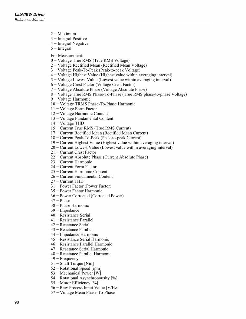
LabVIEW Driver Reference Manual
98
2 − Maximum 3 − Integral Positive 4 − Integral Negative 5 − Integral For Measurement: 0 − Voltage True RMS (True RMS Voltage) 2 − Voltage Rectified Mean (Rectified Mean Voltage) 3 − Voltage Peak-To-Peak (Peak-to-peak Voltage) 4 − Voltage Highest Value (Highest value within averaging interval) 5 − Voltage Lowest Value (Lowest value within averaging interval) 6 − Voltage Crest Factor (Voltage Crest Factor) 7 − Voltage Absolute Phase (Voltage Absolute Phase) 8 − Voltage True RMS Phase-To-Phase (True RMS phase-to-phase Voltage) 9 − Voltage Harmonic 10 − Voltage TRMS Phase-To-Phase Harmonic 11 − Voltage Form Factor 12 − Voltage Harmonic Content 13 − Voltage Fundamental Content 14 − Voltage THD 15 − Current True RMS (True RMS Current) 17 − Current Rectified Mean (Rectified Mean Current) 18 − Current Peak-To-Peak (Peak-to-peak Current) 19 − Current Highest Value (Highest value within averaging interval) 20 − Current Lowest Value (Lowest value within averaging interval) 21 − Current Crest Factor 22 − Current Absolute Phase (Current Absolute Phase) 23 − Current Harmonic 24 − Current Form Factor 25 − Current Harmonic Content 26 − Current Fundamental Content 27 − Current THD 31 − Power Factor (Power Factor) 35 − Power Factor Harmonic 36 − Power Corrected (Corrected Power) 37 − Phase 38 − Phase Harmonic 39 − Impedance 40 − Resistance Serial 41 − Resistance Parallel 42 − Reactance Serial 43 − Reactance Parallel 44 − Impedance Harmonic 45 − Resistance Serial Harmonic 46 − Resistance Parallel Harmonic 47 − Reactance Serial Harmonic 48 − Reactance Parallel Harmonic 49 − Frequency 51 − Shaft Torque [Nm] 52 − Rotational Speed [rpm] 53 − Mechanical Power [W] 54 − Rotational Asynchronousity [%] 55 − Motor Efficiency [%] 56 − Raw Process Input Value [V/Hz] 57 − Voltage Mean Phase-To-Phase
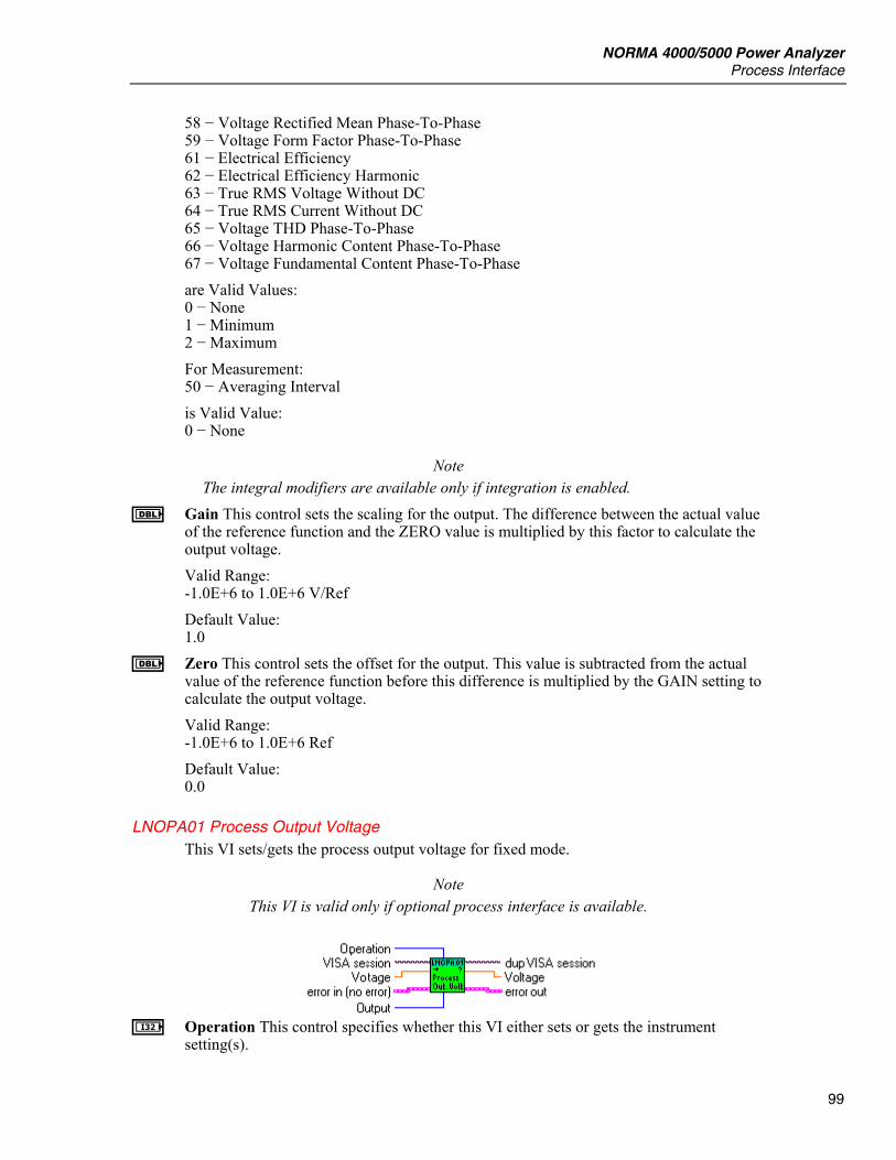
NORMA 4000/5000 Power Analyzer Process Interface
99
58 − Voltage Rectified Mean Phase-To-Phase 59 − Voltage Form Factor Phase-To-Phase 61 − Electrical Efficiency 62 − Electrical Efficiency Harmonic 63 − True RMS Voltage Without DC 64 − True RMS Current Without DC 65 − Voltage THD Phase-To-Phase 66 − Voltage Harmonic Content Phase-To-Phase 67 − Voltage Fundamental Content Phase-To-Phase are Valid Values: 0 − None 1 − Minimum 2 − Maximum For Measurement: 50 − Averaging Interval is Valid Value: 0 − None
Note The integral modifiers are available only if integration is enabled.
E Gain This control sets the scaling for the output. The difference between the actual value of the reference function and the ZERO value is multiplied by this factor to calculate the output voltage. Valid Range: -1.0E+6 to 1.0E+6 V/Ref Default Value: 1.0
E Zero This control sets the offset for the output. This value is subtracted from the actual value of the reference function before this difference is multiplied by the GAIN setting to calculate the output voltage. Valid Range: -1.0E+6 to 1.0E+6 Ref Default Value: 0.0
LNOPA01 Process Output Voltage This VI sets/gets the process output voltage for fixed mode.
Note This VI is valid only if optional process interface is available.
I Operation This control specifies whether this VI either sets or gets the instrument
setting(s).
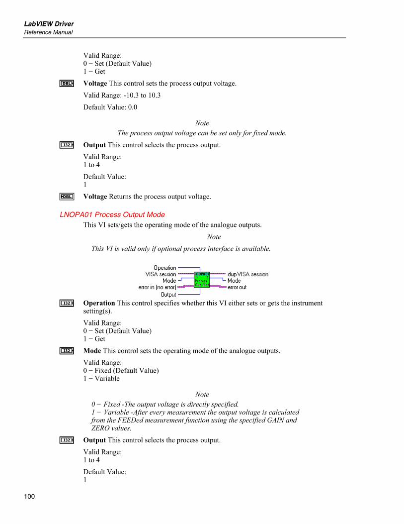
LabVIEW Driver Reference Manual
100
Valid Range: 0 − Set (Default Value) 1 − Get
E Voltage This control sets the process output voltage. Valid Range: -10.3 to 10.3 Default Value: 0.0
Note The process output voltage can be set only for fixed mode.
I Output This control selects the process output. Valid Range: 1 to 4 Default Value: 1
F Voltage Returns the process output voltage.
LNOPA01 Process Output Mode This VI sets/gets the operating mode of the analogue outputs.
Note This VI is valid only if optional process interface is available.
I Operation This control specifies whether this VI either sets or gets the instrument
setting(s). Valid Range: 0 − Set (Default Value) 1 − Get
I Mode This control sets the operating mode of the analogue outputs. Valid Range: 0 − Fixed (Default Value) 1 − Variable
Note 0 − Fixed -The output voltage is directly specified. 1 − Variable -After every measurement the output voltage is calculated from the FEEDed measurement function using the specified GAIN and ZERO values.
I Output This control selects the process output. Valid Range: 1 to 4 Default Value: 1
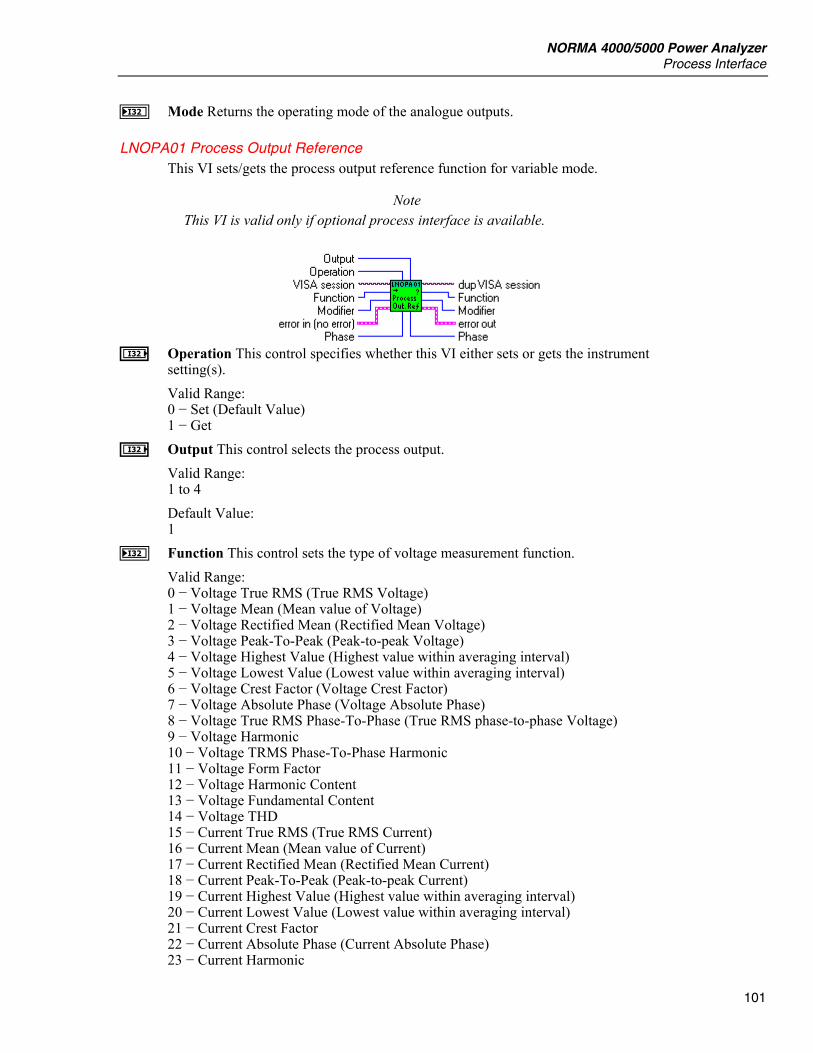
NORMA 4000/5000 Power Analyzer Process Interface
101
J Mode Returns the operating mode of the analogue outputs.
LNOPA01 Process Output Reference This VI sets/gets the process output reference function for variable mode.
Note This VI is valid only if optional process interface is available.
I Operation This control specifies whether this VI either sets or gets the instrument
setting(s). Valid Range: 0 − Set (Default Value) 1 − Get
I Output This control selects the process output. Valid Range: 1 to 4 Default Value: 1
J Function This control sets the type of voltage measurement function. Valid Range: 0 − Voltage True RMS (True RMS Voltage) 1 − Voltage Mean (Mean value of Voltage) 2 − Voltage Rectified Mean (Rectified Mean Voltage) 3 − Voltage Peak-To-Peak (Peak-to-peak Voltage) 4 − Voltage Highest Value (Highest value within averaging interval) 5 − Voltage Lowest Value (Lowest value within averaging interval) 6 − Voltage Crest Factor (Voltage Crest Factor) 7 − Voltage Absolute Phase (Voltage Absolute Phase) 8 − Voltage True RMS Phase-To-Phase (True RMS phase-to-phase Voltage) 9 − Voltage Harmonic 10 − Voltage TRMS Phase-To-Phase Harmonic 11 − Voltage Form Factor 12 − Voltage Harmonic Content 13 − Voltage Fundamental Content 14 − Voltage THD 15 − Current True RMS (True RMS Current) 16 − Current Mean (Mean value of Current) 17 − Current Rectified Mean (Rectified Mean Current) 18 − Current Peak-To-Peak (Peak-to-peak Current) 19 − Current Highest Value (Highest value within averaging interval) 20 − Current Lowest Value (Lowest value within averaging interval) 21 − Current Crest Factor 22 − Current Absolute Phase (Current Absolute Phase) 23 − Current Harmonic
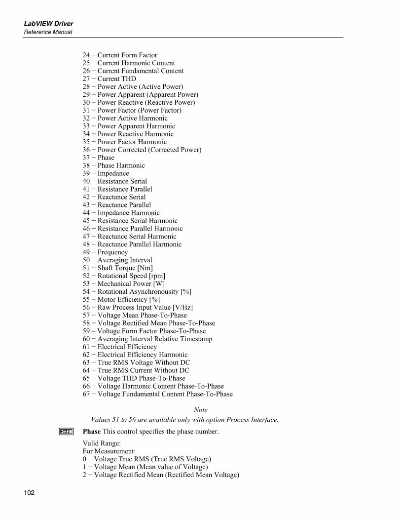
LabVIEW Driver Reference Manual
102
24 − Current Form Factor 25 − Current Harmonic Content 26 − Current Fundamental Content 27 − Current THD 28 − Power Active (Active Power) 29 − Power Apparent (Apparent Power) 30 − Power Reactive (Reactive Power) 31 − Power Factor (Power Factor) 32 − Power Active Harmonic 33 − Power Apparent Harmonic 34 − Power Reactive Harmonic 35 − Power Factor Harmonic 36 − Power Corrected (Corrected Power) 37 − Phase 38 − Phase Harmonic 39 − Impedance 40 − Resistance Serial 41 − Resistance Parallel 42 − Reactance Serial 43 − Reactance Parallel 44 − Impedance Harmonic 45 − Resistance Serial Harmonic 46 − Resistance Parallel Harmonic 47 − Reactance Serial Harmonic 48 − Reactance Parallel Harmonic 49 − Frequency 50 − Averaging Interval 51 − Shaft Torque [Nm] 52 − Rotational Speed [rpm] 53 − Mechanical Power [W] 54 − Rotational Asynchronousity [%] 55 − Motor Efficiency [%] 56 − Raw Process Input Value [V/Hz] 57 − Voltage Mean Phase-To-Phase 58 − Voltage Rectified Mean Phase-To-Phase 59 – Voltage Form Factor Phase-To-Phase 60 − Averaging Interval Relative Timestamp 61 − Electrical Efficiency 62 − Electrical Efficiency Harmonic 63 − True RMS Voltage Without DC 64 − True RMS Current Without DC 65 − Voltage THD Phase-To-Phase 66 − Voltage Harmonic Content Phase-To-Phase 67 − Voltage Fundamental Content Phase-To-Phase
Note Values 51 to 56 are available only with option Process Interface.
J Phase This control specifies the phase number. Valid Range: For Measurement: 0 − Voltage True RMS (True RMS Voltage) 1 − Voltage Mean (Mean value of Voltage) 2 − Voltage Rectified Mean (Rectified Mean Voltage)
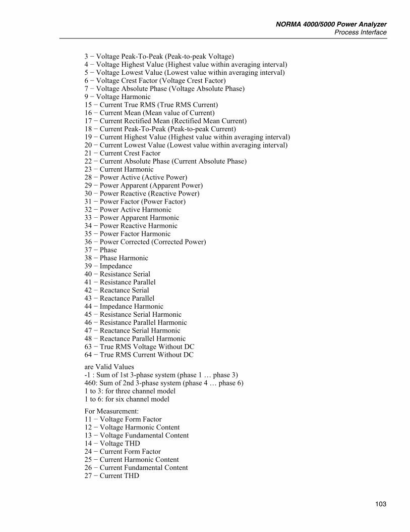
NORMA 4000/5000 Power Analyzer Process Interface
103
3 − Voltage Peak-To-Peak (Peak-to-peak Voltage) 4 − Voltage Highest Value (Highest value within averaging interval) 5 − Voltage Lowest Value (Lowest value within averaging interval) 6 − Voltage Crest Factor (Voltage Crest Factor) 7 − Voltage Absolute Phase (Voltage Absolute Phase) 9 − Voltage Harmonic 15 − Current True RMS (True RMS Current) 16 − Current Mean (Mean value of Current) 17 − Current Rectified Mean (Rectified Mean Current) 18 − Current Peak-To-Peak (Peak-to-peak Current) 19 − Current Highest Value (Highest value within averaging interval) 20 − Current Lowest Value (Lowest value within averaging interval) 21 − Current Crest Factor 22 − Current Absolute Phase (Current Absolute Phase) 23 − Current Harmonic 28 − Power Active (Active Power) 29 − Power Apparent (Apparent Power) 30 − Power Reactive (Reactive Power) 31 − Power Factor (Power Factor) 32 − Power Active Harmonic 33 − Power Apparent Harmonic 34 − Power Reactive Harmonic 35 − Power Factor Harmonic 36 − Power Corrected (Corrected Power) 37 − Phase 38 − Phase Harmonic 39 − Impedance 40 − Resistance Serial 41 − Resistance Parallel 42 − Reactance Serial 43 − Reactance Parallel 44 − Impedance Harmonic 45 − Resistance Serial Harmonic 46 − Resistance Parallel Harmonic 47 − Reactance Serial Harmonic 48 − Reactance Parallel Harmonic 63 − True RMS Voltage Without DC 64 − True RMS Current Without DC are Valid Values -1 : Sum of 1st 3-phase system (phase 1 … phase 3) 460: Sum of 2nd 3-phase system (phase 4 … phase 6) 1 to 3: for three channel model 1 to 6: for six channel model For Measurement: 11 − Voltage Form Factor 12 − Voltage Harmonic Content 13 − Voltage Fundamental Content 14 − Voltage THD 24 − Current Form Factor 25 − Current Harmonic Content 26 − Current Fundamental Content 27 − Current THD
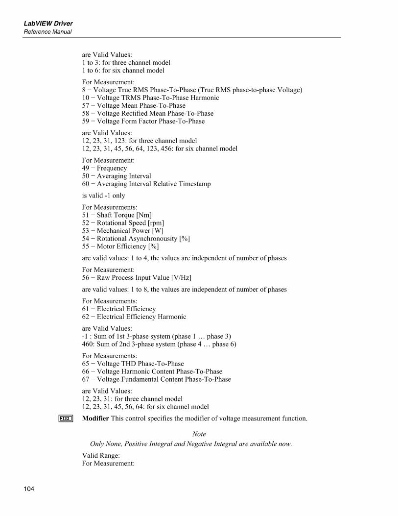
LabVIEW Driver Reference Manual
104
are Valid Values: 1 to 3: for three channel model 1 to 6: for six channel model For Measurement: 8 − Voltage True RMS Phase-To-Phase (True RMS phase-to-phase Voltage) 10 − Voltage TRMS Phase-To-Phase Harmonic 57 − Voltage Mean Phase-To-Phase 58 − Voltage Rectified Mean Phase-To-Phase 59 − Voltage Form Factor Phase-To-Phase are Valid Values: 12, 23, 31, 123: for three channel model 12, 23, 31, 45, 56, 64, 123, 456: for six channel model For Measurement: 49 − Frequency 50 − Averaging Interval 60 − Averaging Interval Relative Timestamp is valid -1 only For Measurements: 51 − Shaft Torque [Nm] 52 − Rotational Speed [rpm] 53 − Mechanical Power [W] 54 − Rotational Asynchronousity [%] 55 − Motor Efficiency [%] are valid values: 1 to 4, the values are independent of number of phases For Measurement: 56 − Raw Process Input Value [V/Hz] are valid values: 1 to 8, the values are independent of number of phases For Measurements: 61 − Electrical Efficiency 62 − Electrical Efficiency Harmonic are Valid Values: -1 : Sum of 1st 3-phase system (phase 1 … phase 3) 460: Sum of 2nd 3-phase system (phase 4 … phase 6) For Measurements: 65 − Voltage THD Phase-To-Phase 66 − Voltage Harmonic Content Phase-To-Phase 67 − Voltage Fundamental Content Phase-To-Phase are Valid Values: 12, 23, 31: for three channel model 12, 23, 31, 45, 56, 64: for six channel model
J Modifier This control specifies the modifier of voltage measurement function.
Note Only None, Positive Integral and Negative Integral are available now.
Valid Range: For Measurement:
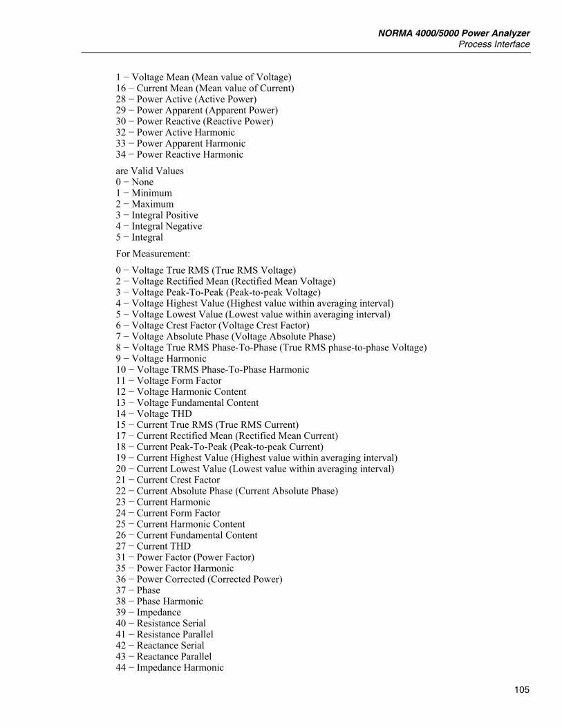
NORMA 4000/5000 Power Analyzer Process Interface
105
1 − Voltage Mean (Mean value of Voltage) 16 − Current Mean (Mean value of Current) 28 − Power Active (Active Power) 29 − Power Apparent (Apparent Power) 30 − Power Reactive (Reactive Power) 32 − Power Active Harmonic 33 − Power Apparent Harmonic 34 − Power Reactive Harmonic are Valid Values 0 − None 1 − Minimum 2 − Maximum 3 − Integral Positive 4 − Integral Negative 5 − Integral For Measurement: 0 − Voltage True RMS (True RMS Voltage) 2 − Voltage Rectified Mean (Rectified Mean Voltage) 3 − Voltage Peak-To-Peak (Peak-to-peak Voltage) 4 − Voltage Highest Value (Highest value within averaging interval) 5 − Voltage Lowest Value (Lowest value within averaging interval) 6 − Voltage Crest Factor (Voltage Crest Factor) 7 − Voltage Absolute Phase (Voltage Absolute Phase) 8 − Voltage True RMS Phase-To-Phase (True RMS phase-to-phase Voltage) 9 − Voltage Harmonic 10 − Voltage TRMS Phase-To-Phase Harmonic 11 − Voltage Form Factor 12 − Voltage Harmonic Content 13 − Voltage Fundamental Content 14 − Voltage THD 15 − Current True RMS (True RMS Current) 17 − Current Rectified Mean (Rectified Mean Current) 18 − Current Peak-To-Peak (Peak-to-peak Current) 19 − Current Highest Value (Highest value within averaging interval) 20 − Current Lowest Value (Lowest value within averaging interval) 21 − Current Crest Factor 22 − Current Absolute Phase (Current Absolute Phase) 23 − Current Harmonic 24 − Current Form Factor 25 − Current Harmonic Content 26 − Current Fundamental Content 27 − Current THD 31 − Power Factor (Power Factor) 35 − Power Factor Harmonic 36 − Power Corrected (Corrected Power) 37 − Phase 38 − Phase Harmonic 39 − Impedance 40 − Resistance Serial 41 − Resistance Parallel 42 − Reactance Serial 43 − Reactance Parallel 44 − Impedance Harmonic

LabVIEW Driver Reference Manual
106
45 − Resistance Serial Harmonic 46 − Resistance Parallel Harmonic 47 − Reactance Serial Harmonic 48 − Reactance Parallel Harmonic 49 − Frequency 51 − Shaft Torque [Nm] 52 − Rotational Speed [rpm] 53 − Mechanical Power [W] 54 − Rotational Asynchronousity [%] 55 − Motor Efficiency [%] 56 − Raw Process Input Value [V/Hz] 57 − Voltage Mean Phase-To-Phase 58 − Voltage Rectified Mean Phase-To-Phase 59 − Voltage Form Factor Phase-To-Phase 61 − Electrical Efficiency 62 − Electrical Efficiency Harmonic 63 − True RMS Voltage Without DC 64 − True RMS Current Without DC 65 − Voltage THD Phase-To-Phase 66 − Voltage Harmonic Content Phase-To-Phase 67 − Voltage Fundamental Content Phase-To-Phase are Valid Values: 0 − None 1 − Minimum 2 − Maximum For Measurement: 50 − Averaging Intervals 60 − Averaging Interval Relative Timestamp is Valid Value: 0 − None
Note The integral modifiers are available only if integration is enabled.
I Function Returns the measurement function. I Phase Returns the phase number. I Modifier Returns the modifier of voltage measurement function.
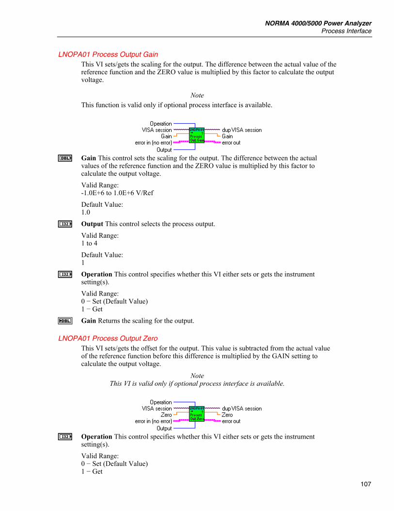
NORMA 4000/5000 Power Analyzer Process Interface
107
LNOPA01 Process Output Gain This VI sets/gets the scaling for the output. The difference between the actual value of the reference function and the ZERO value is multiplied by this factor to calculate the output voltage.
Note This function is valid only if optional process interface is available.
E Gain This control sets the scaling for the output. The difference between the actual
values of the reference function and the ZERO value is multiplied by this factor to calculate the output voltage. Valid Range: -1.0E+6 to 1.0E+6 V/Ref Default Value: 1.0
I Output This control selects the process output. Valid Range: 1 to 4 Default Value: 1
I Operation This control specifies whether this VI either sets or gets the instrument setting(s). Valid Range: 0 − Set (Default Value) 1 − Get
F Gain Returns the scaling for the output.
LNOPA01 Process Output Zero This VI sets/gets the offset for the output. This value is subtracted from the actual value of the reference function before this difference is multiplied by the GAIN setting to calculate the output voltage.
Note This VI is valid only if optional process interface is available.
I Operation This control specifies whether this VI either sets or gets the instrument
setting(s). Valid Range: 0 − Set (Default Value) 1 − Get
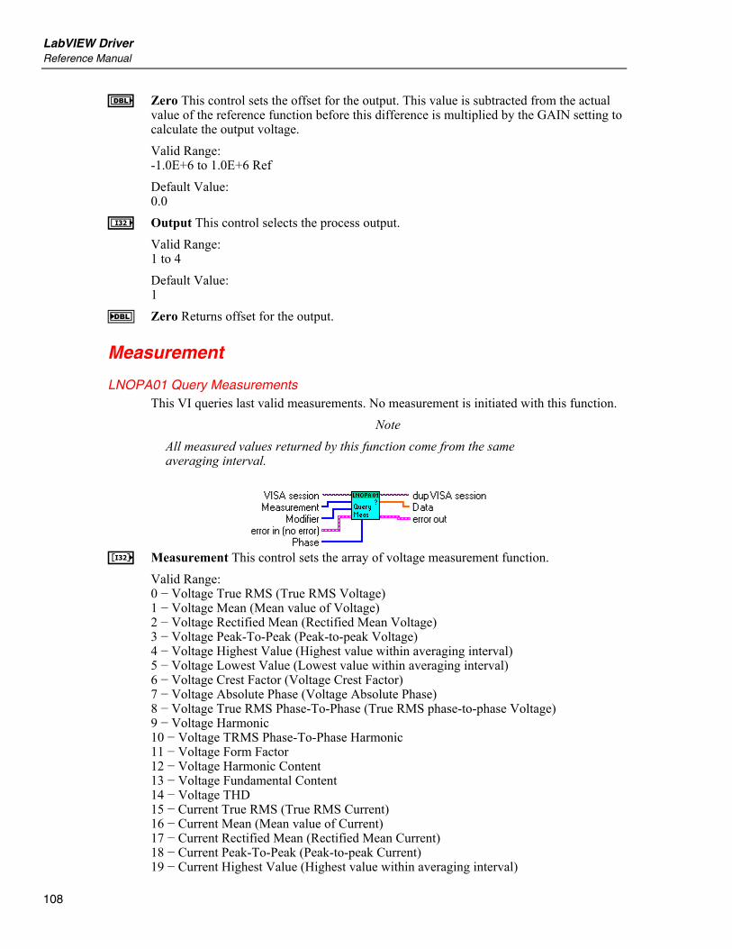
LabVIEW Driver Reference Manual
108
E Zero This control sets the offset for the output. This value is subtracted from the actual value of the reference function before this difference is multiplied by the GAIN setting to calculate the output voltage. Valid Range: -1.0E+6 to 1.0E+6 Ref Default Value: 0.0
I Output This control selects the process output. Valid Range: 1 to 4 Default Value: 1
F Zero Returns offset for the output.
Measurement
LNOPA01 Query Measurements This VI queries last valid measurements. No measurement is initiated with this function.
Note All measured values returned by this function come from the same averaging interval.
L Measurement This control sets the array of voltage measurement function.
Valid Range: 0 − Voltage True RMS (True RMS Voltage) 1 − Voltage Mean (Mean value of Voltage) 2 − Voltage Rectified Mean (Rectified Mean Voltage) 3 − Voltage Peak-To-Peak (Peak-to-peak Voltage) 4 − Voltage Highest Value (Highest value within averaging interval) 5 − Voltage Lowest Value (Lowest value within averaging interval) 6 − Voltage Crest Factor (Voltage Crest Factor) 7 − Voltage Absolute Phase (Voltage Absolute Phase) 8 − Voltage True RMS Phase-To-Phase (True RMS phase-to-phase Voltage) 9 − Voltage Harmonic 10 − Voltage TRMS Phase-To-Phase Harmonic 11 − Voltage Form Factor 12 − Voltage Harmonic Content 13 − Voltage Fundamental Content 14 − Voltage THD 15 − Current True RMS (True RMS Current) 16 − Current Mean (Mean value of Current) 17 − Current Rectified Mean (Rectified Mean Current) 18 − Current Peak-To-Peak (Peak-to-peak Current) 19 − Current Highest Value (Highest value within averaging interval)
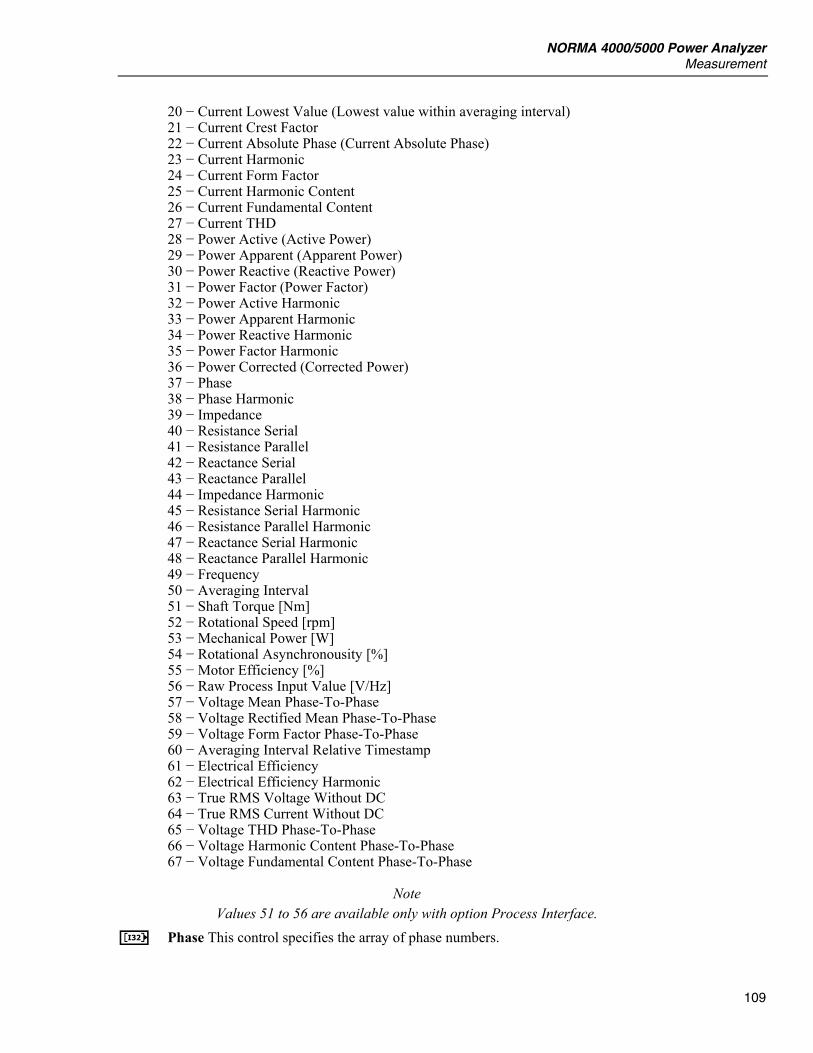
NORMA 4000/5000 Power Analyzer Measurement
109
20 − Current Lowest Value (Lowest value within averaging interval) 21 − Current Crest Factor 22 − Current Absolute Phase (Current Absolute Phase) 23 − Current Harmonic 24 − Current Form Factor 25 − Current Harmonic Content 26 − Current Fundamental Content 27 − Current THD 28 − Power Active (Active Power) 29 − Power Apparent (Apparent Power) 30 − Power Reactive (Reactive Power) 31 − Power Factor (Power Factor) 32 − Power Active Harmonic 33 − Power Apparent Harmonic 34 − Power Reactive Harmonic 35 − Power Factor Harmonic 36 − Power Corrected (Corrected Power) 37 − Phase 38 − Phase Harmonic 39 − Impedance 40 − Resistance Serial 41 − Resistance Parallel 42 − Reactance Serial 43 − Reactance Parallel 44 − Impedance Harmonic 45 − Resistance Serial Harmonic 46 − Resistance Parallel Harmonic 47 − Reactance Serial Harmonic 48 − Reactance Parallel Harmonic 49 − Frequency 50 − Averaging Interval 51 − Shaft Torque [Nm] 52 − Rotational Speed [rpm] 53 − Mechanical Power [W] 54 − Rotational Asynchronousity [%] 55 − Motor Efficiency [%] 56 − Raw Process Input Value [V/Hz] 57 − Voltage Mean Phase-To-Phase 58 − Voltage Rectified Mean Phase-To-Phase 59 − Voltage Form Factor Phase-To-Phase 60 − Averaging Interval Relative Timestamp 61 − Electrical Efficiency 62 − Electrical Efficiency Harmonic 63 − True RMS Voltage Without DC 64 − True RMS Current Without DC 65 − Voltage THD Phase-To-Phase 66 − Voltage Harmonic Content Phase-To-Phase 67 − Voltage Fundamental Content Phase-To-Phase
Note Values 51 to 56 are available only with option Process Interface.
L Phase This control specifies the array of phase numbers.
LabVIEW Driver Reference Manual
110
Valid Range: For Measurement: 0 − Voltage True RMS (True RMS Voltage) 1 − Voltage Mean (Mean value of Voltage) 2 − Voltage Rectified Mean (Rectified Mean Voltage) 3 − Voltage Peak-To-Peak (Peak-to-peak Voltage) 4 − Voltage Highest Value (Highest value within averaging interval) 5 − Voltage Lowest Value (Lowest value within averaging interval) 6 − Voltage Crest Factor (Voltage Crest Factor) 7 − Voltage Absolute Phase (Voltage Absolute Phase) 9 − Voltage Harmonic 15 − Current True RMS (True RMS Current) 16 − Current Mean (Mean value of Current) 17 − Current Rectified Mean (Rectified Mean Current) 18 − Current Peak-To-Peak (Peak-to-peak Current) 19 − Current Highest Value (Highest value within averaging interval) 20 − Current Lowest Value (Lowest value within averaging interval) 21 − Current Crest Factor 22 − Current Absolute Phase (Current Absolute Phase) 23 − Current Harmonic 28 − Power Active (Active Power) 29 − Power Apparent (Apparent Power) 30 − Power Reactive (Reactive Power) 31 − Power Factor (Power Factor) 32 − Power Active Harmonic 33 − Power Apparent Harmonic 34 − Power Reactive Harmonic 35 − Power Factor Harmonic 36 − Power Corrected (Corrected Power) 37 − Phase 38 − Phase Harmonic 39 − Impedance 40 − Resistance Serial 41 − Resistance Parallel 42 − Reactance Serial 43 − Reactance Parallel 44 − Impedance Harmonic 45 − Resistance Serial Harmonic 46 − Resistance Parallel Harmonic 47 − Reactance Serial Harmonic 48 − Reactance Parallel Harmonic 63 − True RMS Voltage Without DC 64 − True RMS Current Without DC are Valid Values -1 : Sum of 1st 3-phase system (phase 1 … phase 3) 460: Sum of 2nd 3-phase system (phase 4 … phase 6) 1 to 3: for three channel model 1 to 6: for six channel model For Measurement: 11 − Voltage Form Factor 12 − Voltage Harmonic Content 13 − Voltage Fundamental Content 14 − Voltage THD 24 − Current Form Factor
NORMA 4000/5000 Power Analyzer Measurement
111
25 − Current Harmonic Content 26 − Current Fundamental Content 27 − Current THD are Valid Values: 1 to 3: for three channel model 1 to 6: for six channel model For Measurement: 8 − Voltage True RMS Phase-To-Phase (True RMS phase-to-phase Voltage) 10 − Voltage TRMS Phase-To-Phase Harmonic 57 − Voltage Mean Phase-To-Phase 58 − Voltage Rectified Mean Phase-To-Phase 59 − Voltage Form Factor Phase-To-Phase are Valid Values: 12, 23, 31,123: for three channel model 12, 23, 31, 45, 56, 64, 123, 456: for six channel model For Measurement: 49 − Frequency 50 − Averaging Interval 60 − Averaging Interval Relative Timestamp is valid -1 only For Measurements: 51 − Shaft Torque [Nm] 52 − Rotational Speed [rpm] 53 − Mechanical Power [W] 54 − Rotational Asynchronousity [%] 55 − Motor Efficiency [%] are valid values: 1 to 4, the values are independent of number of phases For Measurement: 56 − Raw Process Input Value [V/Hz] are valid values: 1 to 8, the values are independent of number of phases For Measurements: 61 − Electrical Efficiency 62 − Electrical Efficiency Harmonic are Valid Values: -1 : Sum of 1st 3-phase system (phase 1 … phase 3) 460: Sum of 2nd 3-phase system (phase 4 … phase 6) For Measurements: 65 − Voltage THD Phase-To-Phase 66 − Voltage Harmonic Content Phase-To-Phase 67 − Voltage Fundamental Content Phase-To-Phase are Valid Values: 12, 23, 31: for three channel model 12, 23, 31, 45, 56, 64: for six channel model
L Modifier This control specifies the array of modifiers of voltage measurement function.
Note Only None, Positive Integral and Negative Integral are available now.

LabVIEW Driver Reference Manual
112
Valid Range: For Measurement: 1 − Voltage Mean (Mean value of Voltage) 16 − Current Mean (Mean value of Current) 28 − Power Active (Active Power) 29 − Power Apparent (Apparent Power) 30 − Power Reactive (Reactive Power) 32 − Power Active Harmonic 33 − Power Apparent Harmonic 34 − Power Reactive Harmonic are Valid Values 0 − None 1 − Minimum 2 − Maximum 3 − Integral Positive 4 − Integral Negative 5 − Integral For Measurement: 0 − Voltage True RMS (True RMS Voltage) 2 − Voltage Rectified Mean (Rectified Mean Voltage) 3 − Voltage Peak-To-Peak (Peak-to-peak Voltage) 4 − Voltage Highest Value (Highest value within averaging interval) 5 − Voltage Lowest Value (Lowest value within averaging interval) 6 − Voltage Crest Factor (Voltage Crest Factor) 7 − Voltage Absolute Phase (Voltage Absolute Phase) 8 − Voltage True RMS Phase-To-Phase (True RMS phase-to-phase Voltage) 9 − Voltage Harmonic 10 − Voltage TRMS Phase-To-Phase Harmonic 11 − Voltage Form Factor 12 − Voltage Harmonic Content 13 − Voltage Fundamental Content 14 − Voltage THD 15 − Current True RMS (True RMS Current) 17 − Current Rectified Mean (Rectified Mean Current) 18 − Current Peak-To-Peak (Peak-to-peak Current) 19 − Current Highest Value (Highest value within averaging interval) 20 − Current Lowest Value (Lowest value within averaging interval) 21 − Current Crest Factor 22 − Current Absolute Phase (Current Absolute Phase) 23 − Current Harmonic 24 − Current Form Factor 25 − Current Harmonic Content 26 − Current Fundamental Content 27 − Current THD 31 − Power Factor (Power Factor) 35 − Power Factor Harmonic 36 − Power Corrected (Corrected Power) 37 − Phase 38 − Phase Harmonic 39 − Impedance 40 − Resistance Serial 41 − Resistance Parallel 42 − Reactance Serial
NORMA 4000/5000 Power Analyzer Measurement
113
43 − Reactance Parallel 44 − Impedance Harmonic 45 − Resistance Serial Harmonic 46 − Resistance Parallel Harmonic 47 − Reactance Serial Harmonic 48 − Reactance Parallel Harmonic 49 − Frequency 51 − Shaft Torque [Nm] 52 − Rotational Speed [rpm] 53 − Mechanical Power [W] 54 − Rotational Asynchronousity [%] 55 − Motor Efficiency [%] 56 − Raw Process Input Value [V/Hz] 57 − Voltage Mean Phase-To-Phase 58 − Voltage Rectified Mean Phase-To-Phase 59 − Voltage Form Factor Phase-To-Phase 61 − Electrical Efficiency 62 − Electrical Efficiency Harmonic 63 − True RMS Voltage Without DC 64 − True RMS Current Without DC 65 − Voltage THD Phase-To-Phase 66 − Voltage Harmonic Content Phase-To-Phase 67 − Voltage Fundamental Content Phase-To-Phase are Valid Values: 0 − None 1 − Minimum 2 − Maximum For Measurement: 50 − Averaging Intervals 60 − Averaging Interval Relative Timestamp is Valid Value: 0 − None
Note The integral modifiers are available only if integration is enabled.
G Data This indicator returns values of selected measurements in basic units.

LabVIEW Driver Reference Manual
114
LNOPA01 Query Measurements with Status Num This VI queries the last valid measurements along with the status of each measurement.
Note (1) All measured values returned by this VI come from the same averaging interval. (2) The Status is returned in UInt32 array. For UInt8 array see LNOPA01 Query Measurement Status.vi this vi was used in previous driver versions.
L Measurement This control sets the array of voltage measurement function.
Valid Range: 0 − Voltage True RMS (True RMS Voltage) 1 − Voltage Mean (Mean value of Voltage) 2 − Voltage Rectified Mean (Rectified Mean Voltage) 3 − Voltage Peak-To-Peak (Peak-to-peak Voltage) 4 − Voltage Highest Value (Highest value within averaging interval) 5 − Voltage Lowest Value (Lowest value within averaging interval) 6 − Voltage Crest Factor (Voltage Crest Factor) 7 − Voltage Absolute Phase (Voltage Absolute Phase) 8 − Voltage True RMS Phase-To-Phase (True RMS phase-to-phase Voltage) 9 − Voltage Harmonic 10 − Voltage TRMS Phase-To-Phase Harmonic 11 − Voltage Form Factor 12 − Voltage Harmonic Content 13 − Voltage Fundamental Content 14 − Voltage THD 15 − Current True RMS (True RMS Current) 16 − Current Mean (Mean value of Current) 17 − Current Rectified Mean (Rectified Mean Current) 18 − Current Peak-To-Peak (Peak-to-peak Current) 19 − Current Highest Value (Highest value within averaging interval) 20 − Current Lowest Value (Lowest value within averaging interval) 21 − Current Crest Factor 22 − Current Absolute Phase (Current Absolute Phase) 23 − Current Harmonic 24 − Current Form Factor 25 − Current Harmonic Content 26 − Current Fundamental Content 27 − Current THD 28 − Power Active (Active Power) 29 − Power Apparent (Apparent Power) 30 − Power Reactive (Reactive Power) 31 − Power Factor (Power Factor) 32 − Power Active Harmonic 33 − Power Apparent Harmonic 34 − Power Reactive Harmonic 35 − Power Factor Harmonic 36 − Power Corrected (Corrected Power)
NORMA 4000/5000 Power Analyzer Measurement
115
37 − Phase 38 − Phase Harmonic 39 − Impedance 40 − Resistance Serial 41 − Resistance Parallel 42 − Reactance Serial 43 − Reactance Parallel 44 − Impedance Harmonic 45 − Resistance Serial Harmonic 46 − Resistance Parallel Harmonic 47 − Reactance Serial Harmonic 48 − Reactance Parallel Harmonic 49 − Frequency 50 − Averaging Interval 51 − Shaft Torque [Nm] 52 − Rotational Speed [rpm] 53 − Mechanical Power [W] 54 − Rotational Asynchronousity [%] 55 − Motor Efficiency [%] 56 − Raw Process Input Value [V/Hz] 57 − Voltage Mean Phase-To-Phase 58 − Voltage Rectified Mean Phase-To-Phase 59 − Voltage Form Factor Phase-To-Phase 60 − Averaging Interval Relative Timestamp 61 − Electrical Efficiency 62 − Electrical Efficiency Harmonic 63 − True RMS Voltage Without DC 64 − True RMS Current Without DC 65 − Voltage THD Phase-To-Phase 66 − Voltage Harmonic Content Phase-To-Phase 67 − Voltage Fundamental Content Phase-To-Phase
Note Values 51 to 56 are available only with option Process Interface.
L Phase This control specifies the array of phase numbers. Valid Range: For Measurement: 0 − Voltage True RMS (True RMS Voltage) 1 − Voltage Mean (Mean value of Voltage) 2 − Voltage Rectified Mean (Rectified Mean Voltage) 3 − Voltage Peak-To-Peak (Peak-to-peak Voltage) 4 − Voltage Highest Value (Highest value within averaging interval) 5 − Voltage Lowest Value (Lowest value within averaging interval) 6 – Voltage Crest Factor (Voltage Crest Factor) 7 − Voltage Absolute Phase (Voltage Absolute Phase) 9 − Voltage Harmonic 15 − Current True RMS (True RMS Current) 16 − Current Mean (Mean value of Current) 17 − Current Rectified Mean (Rectified Mean Current) 18 − Current Peak-To-Peak (Peak-to-peak Current) 19 − Current Highest Value (Highest value within averaging interval) 20 − Current Lowest Value (Lowest value within averaging interval) 21 − Current Crest Factor
LabVIEW Driver Reference Manual
116
22 − Current Absolute Phase (Current Absolute Phase) 23 − Current Harmonic 28 − Power Active (Active Power) 29 − Power Apparent (Apparent Power) 30 − Power Reactive (Reactive Power) 31 − Power Factor (Power Factor) 32 − Power Active Harmonic 33 − Power Apparent Harmonic 34 − Power Reactive Harmonic 35 − Power Factor Harmonic 36 − Power Corrected (Corrected Power) 37 − Phase 38 − Phase Harmonic 39 − Impedance 40 − Resistance Serial 41 − Resistance Parallel 42 − Reactance Serial 43 − Reactance Parallel 44 − Impedance Harmonic 45 − Resistance Serial Harmonic 46 − Resistance Parallel Harmonic 47 − Reactance Serial Harmonic 48 − Reactance Parallel Harmonic 63 − True RMS Voltage Without DC 64 − True RMS Current Without DC are Valid Values -1 : Sum of 1st 3-phase system (phase 1 … phase 3) 460: Sum of 2nd 3-phase system (phase 4 … phase 6) 1 to 3: for three channel model 1 to 6: for six channel model For Measurement: 11 − Voltage Form Factor 12 − Voltage Harmonic Content 13 − Voltage Fundamental Content 14 − Voltage THD 24 − Current Form Factor 25 − Current Harmonic Content 26 − Current Fundamental Content 27 − Current THD are Valid Values: 1 to 3: for three channel model 1 to 6: for six channel model For Measurement: 8 − Voltage True RMS Phase-To-Phase (True RMS phase-to-phase Voltage) 10 − Voltage TRMS Phase-To-Phase Harmonic 57 − Voltage Mean Phase-To-Phase 58 − Voltage Rectified Mean Phase-To-Phase 59 − Voltage Form Factor Phase-To-Phase are Valid Values: 12, 23, 31, 123: for three channel model 12, 23, 31, 45, 56, 64, 123, 456: for six channel model
NORMA 4000/5000 Power Analyzer Measurement
117
For Measurement: 49 − Frequency 50 − Averaging Interval 60 − Averaging Interval Relative Timestamp is valid -1 only For Measurements: 51 − Shaft Torque [Nm] 52 − Rotational Speed [rpm] 53 − Mechanical Power [W] 54 − Rotational Asynchronousity [%] 55 − Motor Efficiency [%] are valid values: 1 to 4, the values are independent of number of phases For Measurement: 56 − Raw Process Input Value [V/Hz] are valid values: 1 to 8, the values are independent of number of phases For Measurements: 61 − Electrical Efficiency 62 − Electrical Efficiency Harmonic are Valid Values: -1 : Sum of 1st 3-phase system (phase 1 … phase 3) 460: Sum of 2nd 3-phase system (phase 4 … phase 6) For Measurements: 65 − Voltage THD Phase-To-Phase 66 − Voltage Harmonic Content Phase-To-Phase 67 − Voltage Fundamental Content Phase-To-Phase are Valid Values: 12, 23, 31: for three channel model 12, 23, 31, 45, 56, 64: for six channel model
L Modifier This control specifies the array of modifiers of voltage measurement function.
Note Only None, Positive Integral and Negative Integral are available now.
Valid Range: For Measurement: 1 − Voltage Mean (Mean value of Voltage) 16 − Current Mean (Mean value of Current) 28 − Power Active (Active Power) 29 − Power Apparent (Apparent Power) 30 − Power Reactive (Reactive Power) 32 − Power Active Harmonic 33 − Power Apparent Harmonic 34 − Power Reactive Harmonic are Valid Values 0 − None 1 − Minimum 2 − Maximum 3 − Integral Positive
LabVIEW Driver Reference Manual
118
4 − Integral Negative 5 − Integral For Measurement: 0 − Voltage True RMS (True RMS Voltage) 2 − Voltage Rectified Mean (Rectified Mean Voltage) 3 − Voltage Peak-To-Peak (Peak-to-peak Voltage) 4 − Voltage Highest Value (Highest value within averaging interval) 5 − Voltage Lowest Value (Lowest value within averaging interval) 6 − Voltage Crest Factor (Voltage Crest Factor) 7 − Voltage Absolute Phase (Voltage Absolute Phase) 8 − Voltage True RMS Phase-To-Phase (True RMS phase-to-phase Voltage) 9 − Voltage Harmonic 10 − Voltage TRMS Phase-To-Phase Harmonic 11 − Voltage Form Factor 12 − Voltage Harmonic Content 13 − Voltage Fundamental Content 14 − Voltage THD 15 − Current True RMS (True RMS Current) 17 − Current Rectified Mean (Rectified Mean Current) 18 − Current Peak-To-Peak (Peak-to-peak Current) 19 − Current Highest Value (Highest value within averaging interval) 20 − Current Lowest Value (Lowest value within averaging interval) 21 − Current Crest Factor 22 − Current Absolute Phase (Current Absolute Phase) 23 − Current Harmonic 24 − Current Form Factor 25 − Current Harmonic Content 26 − Current Fundamental Content 27 − Current THD 31 − Power Factor (Power Factor) 35 − Power Factor Harmonic 36 − Power Corrected (Corrected Power) 37 − Phase 38 − Phase Harmonic 39 − Impedance 40 − Resistance Serial 41 − Resistance Parallel 42 − Reactance Serial 43 − Reactance Parallel 44 − Impedance Harmonic 45 − Resistance Serial Harmonic 46 − Resistance Parallel Harmonic 47 − Reactance Serial Harmonic 48 − Reactance Parallel Harmonic 49 − Frequency 51 − Shaft Torque [Nm] 52 − Rotational Speed [rpm] 53 − Mechanical Power [W] 54 − Rotational Asynchronousity [%] 55 − Motor Efficiency [%] 56 − Raw Process Input Value [V/Hz] 57 − Voltage Mean Phase-To-Phase 58 − Voltage Rectified Mean Phase-To-Phase 59 − Voltage Form Factor Phase-To-Phase
NORMA 4000/5000 Power Analyzer Measurement
119
61 − Electrical Efficiency 62 − Electrical Efficiency Harmonic 63 − True RMS Voltage Without DC 64 − True RMS Current Without DC 65 − Voltage THD Phase-To-Phase 66 − Voltage Harmonic Content Phase-To-Phase 67 − Voltage Fundamental Content Phase-To-Phase are Valid Values: 0 − None 1 − Minimum 2 − Maximum For Measurement: 50 − Averaging Intervals 60 − Averaging Interval Relative Timestamp is Valid Value: 0 − None
Note The integral modifiers are available only if integration is enabled.
G Data This indicator returns values of selected measurements. S Status Returns status of the measurement on the corresponding index.
Valid Values: 0 − normal 1 − underrange 2 − overrange 8 − invalid
Note (1) Underrange -The returned value is valid, but the signal amplitude is too low for the given range, so the measurement precision is reduced. (2) Overrange -The instrument returns a measurement value, but the input signal amplitude is too high for the given range. This causes the input signal to be clipped to an amplitude within the current range. Because the measurement value is calculated from clipped sampled data, the returned value can be more or less outside the specification. (3) Undefined -The instrument was not able to calculate a valid value or the requested function is no longer available. This could be caused by e.g. loss of synchronization (no valid frequency, harmonics, ...). The instrument returns an Not A Number for the measurement.
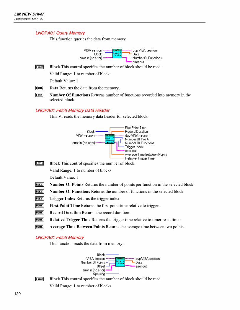
LabVIEW Driver Reference Manual
120
LNOPA01 Query Memory This function queries the data from memory.
I Block This control specifies the number of block should be read.
Valid Range: 1 to number of block Default Value: 1
G Data Returns the data from the memory. J Number Of Functions Returns number of functions recorded into memory in the
selected block.
LNOPA01 Fetch Memory Data Header This VI reads the memory data header for selected block.
I Block This control specifies the number of block.
Valid Range: 1 to number of blocks Default Value: 1
J Number Of Points Returns the number of points per function in the selected block. J Number Of Functions Returns the number of functions in the selected block. J Trigger Index Returns the trigger index. F First Point Time Returns the first point time relative to trigger. F Record Duration Returns the record duration. F Relative Trigger Time Returns the trigger time relative to timer reset time. F Average Time Between Points Returns the average time between two points.
LNOPA01 Fetch Memory This function reads the data from memory.
I Block This control specifies the number of block should be read.
Valid Range: 1 to number of blocks

NORMA 4000/5000 Power Analyzer Measurement
121
Default Value: 1 I Number Of Points This control specifies the number of sparsed averaging
intervals/samples. It means the number of points for each function stored into memory. Valid Range: 1 to number of points Default Value: 1
Note This number determines the number of points will be returned for each function. It doesn't mean the total returned number of points. Example: Three functions are stored into memory (Voltage, current and power on phase 1). The Number Of Points 1000 means, that 1000 point for each function will be returned. Altogether, it will be 3000 points.
I Offset This control specifies the offset in memory. The data from memory will be read from this offset.
Note Example: There are 1000 points stored into memory. Offset is set to 50. The first returned points has index 50 in the memory.
I Sparsing This control specifies the sparsing. Valid Values: 1 to number of points Default Value: 1
Note The sparsing is the step between the returned points. Example: There are 1000 points per function stored into memory. Offset is set to 0 and sparsing to 10. The returned points have the indexes 0, 10, 20 ... in the memory.
G Data Returns the data from instrument memory.
Note The data are grouped by intervals/lines. It means, that the data are stored in the array in order F1(t1),F2(t1)... Fn(t1),F1(t2),F2(t2)...Fn(t2), ... , F1(tn),F2(tn) ... Fn(tn) Example: There are Voltage, Current and Power on phase 1 stored in the memory. The data are returned in order U1(t1),I1(t1),P1(t1),U1(t2),I1(t2),P1(t2) .... F Numeric

LabVIEW Driver Reference Manual
122
LNOPA01 Fetch Spectrum Data Header This function reads the spectrum preamble.
F Block Start Time Returns the seconds relative to timer reset time (call LNOPA01 Query
Timer Reset Time.vi to get timer reset time). J Number Of Lines Returns the number of points (spectrum lines) per function. J Number Of Functions Returns the number of functions configured for spectrum
calculation. G Step List Returns the list of frequency steps (FFT) or fundamental frequencies(DFT).
LNOPA01 Fetch Spectrum This function reads the spectrum data.
I Lines This control specifies the number of lines should be read.
Valid Range: 0 to number of lines Default value: 1
Note If this parameter is set to 0, all lines are read.
I Offset This control specifies the start line, should be return. Valid Range: 0 to number of lines Default Value: 0
Note (1) If the lines + offset exceeds the highest line, the error "-222, Data out of range" is generated. (2) If this function is sent during harmonic measurement or if no harmonics measurement has been performed the error "-230, Data corrupt or state" is generated.
G Data Returns the spectrum data.

NORMA 4000/5000 Power Analyzer Utility
123
Note The data are grouped by lines. It means, that the data are stored in the array in order F1(t1),F2(t1)... Fn(t1),F1(t2),F2(t2)...Fn(t2), ... , F1(tn),F2(tn) ... Fn(tn) Example: There are functions Voltage, Current and Power on phase 1 configured for spectrum calculation. The data are returned in order U1(t1),I1(t1),P1(t1),U1(t2),I1(t2),P1(t2) ....
LNOPA01 Actual Memory Block Count This function returns the number of blocks acquired in memory.
J Number Of Blocks Returns the number of blocks in the memory.
LNOPA01 Free Memory This function returns the free bytes in memory.
J Free Memory Bytes Returns the free memory bytes.
LNOPA01 Memory Abort This function aborts the memory recording and resets the operation bits.
Utility
LNOPA01 Self-Test This VI causes the instrument to perform a self-test and returns the results.
B Self-Test Response Returns the string returned from the self test. See the device's
operation manual for an explanation of the string's contents. R Self-Test Error This control contains the value returned from the instrument self test.
Zero means success. For any other code, see the device's operator's manual.
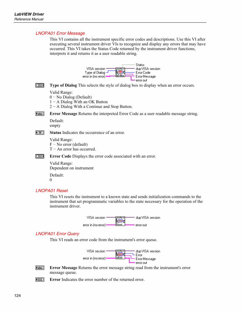
LabVIEW Driver Reference Manual
124
LNOPA01 Error Message This VI contains all the instrument specific error codes and descriptions. Use this VI after executing several instrument driver VIs to recognize and display any errors that may have occurred. This VI takes the Status Code returned by the instrument driver functions, interprets it and returns it as a user readable string.
I Type of Dialog This selects the style of dialog box to display when an error occurs.
Valid Range: 0 − No Dialog (Default) 1 − A Dialog With an OK Button 2 − A Dialog With a Continue and Stop Button.
B Error Message Returns the interpreted Error Code as a user readable message string. Default: empty
f Status Indicates the occurrence of an error. Valid Range: F − No error (default) T − An error has occurred.
I Error Code Displays the error code associated with an error. Valid Range: Dependent on instrument Default: 0
LNOPA01 Reset This VI resets the instrument to a known state and sends initialization commands to the instrument that set programmatic variables to the state necessary for the operation of the instrument driver.
LNOPA01 Error Query This VI reads an error code from the instrument's error queue.
B Error Message Returns the error message string read from the instrument's error
message queue. J Error Indicates the error number of the returned error.
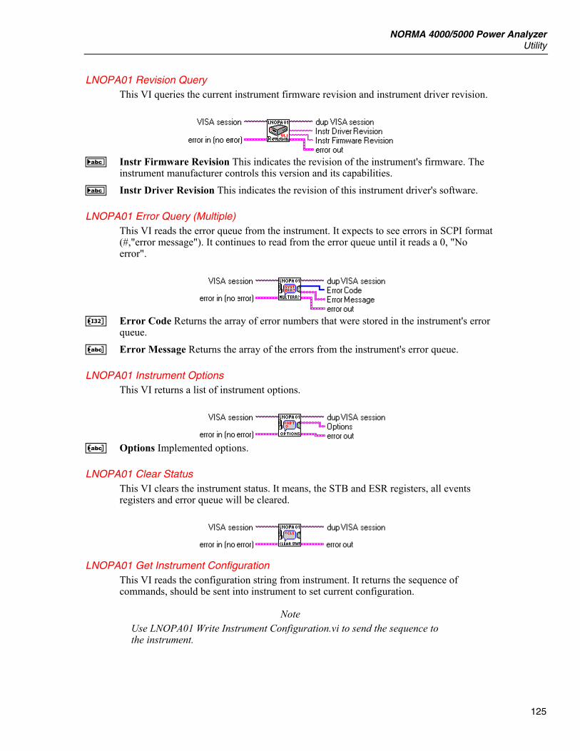
NORMA 4000/5000 Power Analyzer Utility
125
LNOPA01 Revision Query This VI queries the current instrument firmware revision and instrument driver revision.
B Instr Firmware Revision This indicates the revision of the instrument's firmware. The
instrument manufacturer controls this version and its capabilities. B Instr Driver Revision This indicates the revision of this instrument driver's software.
LNOPA01 Error Query (Multiple) This VI reads the error queue from the instrument. It expects to see errors in SCPI format (#,"error message"). It continues to read from the error queue until it reads a 0, "No error".
K Error Code Returns the array of error numbers that were stored in the instrument's error
queue. C Error Message Returns the array of the errors from the instrument's error queue.
LNOPA01 Instrument Options This VI returns a list of instrument options.
C Options Implemented options.
LNOPA01 Clear Status This VI clears the instrument status. It means, the STB and ESR registers, all events registers and error queue will be cleared.
LNOPA01 Get Instrument Configuration This VI reads the configuration string from instrument. It returns the sequence of commands, should be sent into instrument to set current configuration.
Note Use LNOPA01 Write Instrument Configuration.vi to send the sequence to the instrument.
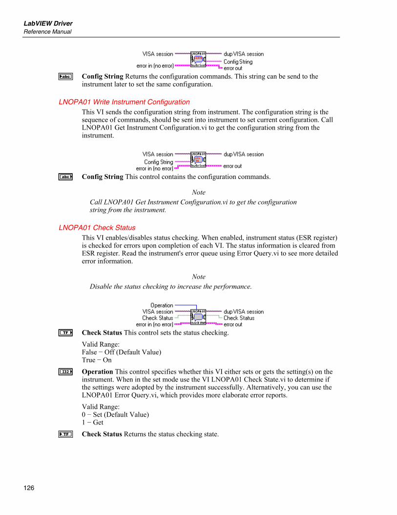
LabVIEW Driver Reference Manual
126
B Config String Returns the configuration commands. This string can be send to the
instrument later to set the same configuration.
LNOPA01 Write Instrument Configuration This VI sends the configuration string from instrument. The configuration string is the sequence of commands, should be sent into instrument to set current configuration. Call LNOPA01 Get Instrument Configuration.vi to get the configuration string from the instrument.
A Config String This control contains the configuration commands.
Note Call LNOPA01 Get Instrument Configuration.vi to get the configuration string from the instrument.
LNOPA01 Check Status This VI enables/disables status checking. When enabled, instrument status (ESR register) is checked for errors upon completion of each VI. The status information is cleared from ESR register. Read the instrument's error queue using Error Query.vi to see more detailed error information.
Note Disable the status checking to increase the performance.
e Check Status This control sets the status checking.
Valid Range: False − Off (Default Value) True − On
I Operation This control specifies whether this VI either sets or gets the setting(s) on the instrument. When in the set mode use the VI LNOPA01 Check State.vi to determine if the settings were adopted by the instrument successfully. Alternatively, you can use the LNOPA01 Error Query.vi, which provides more elaborate error reports. Valid Range: 0 − Set (Default Value) 1 − Get
f Check Status Returns the status checking state.