Embed Size (px)
Citation preview

Doc. no.: 9.17.078E Date: 22-01-2018
ATTENTIONPlease read this Instruction Manual carefully before installing and operating the instrument.
Not following the guidelines could result in personal injury and/or damage to the equipment.
FLOW-BUS LabVIEW™ Driver
Instruction Manual

Bronkhorst®
Instruction Manual FLOW-BUS LabVIEW™ Driver 9.17.078E2
Disclaimer
The information in this manual has been reviewed and is believed to be wholly reliable. No responsibility, however, isassumed for inaccuracies. The material in this manual is for information purposes only.
Copyright
© 2018 Bronkhorst High-Tech B.V.All rights reserved. This documentation is protected by copyright.
Subject to technical and optical changes as well as printing errors. The information contained in this document is subject tochange at any time without prior notification. Bronkhorst High-Tech B.V. reserves the right to modify or improve itsproducts and modify the contents without being obliged to inform any particular persons or organizations. The devicespecifications and the contents of the package may deviate from what is stated in this document.
Symbols
Important information. Discarding this information could cause injuries to people or damage to instrumentation orinstallation.
Helpful information.
Additional info, available on the internet or from your local sales representative.

Bronkhorst®
Instruction Manual FLOW-BUS LabVIEW™ Driver9.17.078E 3
Table of contents
. . . . . . . . . . . . . . . . . . . . . . . . . . . . . . . . . . . . . . . . . . . . . . . . . . . . . . . . . . . . . . . . . . . . . . . . . . . . . . . . . . . . . . . . . . . . . . . . . . . . . . . . . . . . 4Introduction 1. . . . . . . . . . . . . . . . . . . . . . . . . . . . . . . . . . . . . . . . . . . . . . . . . . . . . . . . . . . . . . . . . . . . . . . . . . . . . . . . . . . . . . . . . . . . . . . . . . . . . . . . . . . . 41.1 Product description . . . . . . . . . . . . . . . . . . . . . . . . . . . . . . . . . . . . . . . . . . . . . . . . . . . . . . . . . . . . . . . . . . . . . . . . . . . . . . . . . . . . . . . . . . . . . . . . . . . . . . . . . . . . 41.2 Other documents . . . . . . . . . . . . . . . . . . . . . . . . . . . . . . . . . . . . . . . . . . . . . . . . . . . . . . . . . . . . . . . . . . . . . . . . . . . . . . . . . . . . . . . . . . . . . . . . . . . . . . . . . . . . 41.3 Supported instruments . . . . . . . . . . . . . . . . . . . . . . . . . . . . . . . . . . . . . . . . . . . . . . . . . . . . . . . . . . . . . . . . . . . . . . . . . . . . . . . . . . . . . . . . . . . . . . . . . . . . . . . . . . . . 41.4 System requirements
. . . . . . . . . . . . . . . . . . . . . . . . . . . . . . . . . . . . . . . . . . . . . . . . . . . . . . . . . . . . . . . . . . . . . . . . . . . . . . . . . . . . . . . . . . . . . . . . . . . . . . . . . . . . 5Installation 2. . . . . . . . . . . . . . . . . . . . . . . . . . . . . . . . . . . . . . . . . . . . . . . . . . . . . . . . . . . . . . . . . . . . . . . . . . . . . . . . . . . . . . . . . . . . . . . . . . . . . . . . . . . . 52.1 NI Instrument Driver Finder . . . . . . . . . . . . . . . . . . . . . . . . . . . . . . . . . . . . . . . . . . . . . . . . . . . . . . . . . . . . . . . . . . . . . . . . . . . . . . . . . . . . . . . . . . . . . . . . . . . . . . . . . . . . 52.2 Manual installation
. . . . . . . . . . . . . . . . . . . . . . . . . . . . . . . . . . . . . . . . . . . . . . . . . . . . . . . . . . . . . . . . . . . . . . . . . . . . . . . . . . . . . . . . . . . . . . . . . . . . . . . . . . . . 6Interfaces 3. . . . . . . . . . . . . . . . . . . . . . . . . . . . . . . . . . . . . . . . . . . . . . . . . . . . . . . . . . . . . . . . . . . . . . . . . . . . . . . . . . . . . . . . . . . . . . . . . . . . . . . . . . . . 63.1 RS232 on multibus instrument . . . . . . . . . . . . . . . . . . . . . . . . . . . . . . . . . . . . . . . . . . . . . . . . . . . . . . . . . . . . . . . . . . . . . . . . . . . . . . . . . . . . . . . . . . . . . . . . . . . . . . . . . . . . 73.2 RS232/FLOW-BUS interface
. . . . . . . . . . . . . . . . . . . . . . . . . . . . . . . . . . . . . . . . . . . . . . . . . . . . . . . . . . . . . . . . . . . . . . . . . . . . . . . . . . . . . . . . . . . . . . . . . . . . . . . . . . . . 8Operation 4. . . . . . . . . . . . . . . . . . . . . . . . . . . . . . . . . . . . . . . . . . . . . . . . . . . . . . . . . . . . . . . . . . . . . . . . . . . . . . . . . . . . . . . . . . . . . . . . . . . . . . . . . . . . 84.1 Accessing driver VIs . . . . . . . . . . . . . . . . . . . . . . . . . . . . . . . . . . . . . . . . . . . . . . . . . . . . . . . . . . . . . . . . . . . . . . . . . . . . . . . . . . . . . . . . . . . . . . . . . . . . . . . . . . . . 84.2 Driver structure . . . . . . . . . . . . . . . . . . . . . . . . . . . . . . . . . . . . . . . . . . . . . . . . . . . . . . . . . . . . . . . . . . . . . . . . . . . . . . . . . . . . . . . . . . . . . . . . . . . . . . . . . . . . 9Basic application structure 4.2.1
. . . . . . . . . . . . . . . . . . . . . . . . . . . . . . . . . . . . . . . . . . . . . . . . . . . . . . . . . . . . . . . . . . . . . . . . . . . . . . . . . . . . . . . . . . . . . . . . . . . . . . . . . . . . 9Standard driver VI structure 4.2.2
. . . . . . . . . . . . . . . . . . . . . . . . . . . . . . . . . . . . . . . . . . . . . . . . . . . . . . . . . . . . . . . . . . . . . . . . . . . . . . . . . . . . . . . . . . . . . . . . . . . . . . . . . . . . 11Instrument Driver Error Codes 4.2.3
. . . . . . . . . . . . . . . . . . . . . . . . . . . . . . . . . . . . . . . . . . . . . . . . . . . . . . . . . . . . . . . . . . . . . . . . . . . . . . . . . . . . . . . . . . . . . . . . . . . . . . . . . . . . 124.3 Adding driver VI
. . . . . . . . . . . . . . . . . . . . . . . . . . . . . . . . . . . . . . . . . . . . . . . . . . . . . . . . . . . . . . . . . . . . . . . . . . . . . . . . . . . . . . . . . . . . . . . . . . . . . . . . . . . . 12Sending parameter 4.3.1
. . . . . . . . . . . . . . . . . . . . . . . . . . . . . . . . . . . . . . . . . . . . . . . . . . . . . . . . . . . . . . . . . . . . . . . . . . . . . . . . . . . . . . . . . . . . . . . . . . . . . . . . . . . . 12Requesting parameter 4.3.2
. . . . . . . . . . . . . . . . . . . . . . . . . . . . . . . . . . . . . . . . . . . . . . . . . . . . . . . . . . . . . . . . . . . . . . . . . . . . . . . . . . . . . . . . . . . . . . . . . . . . . . . . . . . . 13Example 4.3.3
. . . . . . . . . . . . . . . . . . . . . . . . . . . . . . . . . . . . . . . . . . . . . . . . . . . . . . . . . . . . . . . . . . . . . . . . . . . . . . . . . . . . . . . . . . . . . . . . . . . . . . . . . . . . 15Service 5

Bronkhorst®
Instruction Manual FLOW-BUS LabVIEW™ Driver 9.17.078E4
1 Introduction
1.1 Product descriptionThe Bronkhorst® FLOW-BUS driver is a set of LabVIEW™ VIs (VirtualInstruments) that implement the serial ASCII commands used on the FLOW-BUS. The VIs also handle the conversion of data that is sent to or receivedfrom an instrument.For more information about the commands and the data exchanged, pleaserefer to the RS232 interface with FLOW-BUS protocol manual (document no.9.17.027) or to the operation instructions digital instruments manual (document no. 9.17.023).
Along with the driver some example VIs are included to demonstrate the structure of an application that utilizes the driverVIs. The examples can also be used to test communication with an instrument, as the examples are all tested and functional.
The driver documentation is aimed at individuals with a reasonable working understanding of LabVIEW™, and is notintended as a tutorial to developing applications written in the LabVIEW™ environment.
1.2 Other documentsManuals and guides for Bronkhorst® instruments are modular. General instructions give information about thefunctionality and installation of instruments. Operational instructions explain the use of the digital instruments featuresand parameters. Fieldbus specific information explains the installation and use of the fieldbus installed on the instrument.
Type Document name Document no.
Manuals Operation instructions digital instruments 9.17.023
FLOW-BUS interface 9.17.024
RS232 interface with FLOW-BUS protocol 9.17.027
Technical documentation Hook-up diagram laboratory-style MBC RS232 + analog 9.16.062
Hook-up diagram industrial style MBC RS232 + analog 9.16.051
Hook-up diagram CORI-FLOW RS232 + analog 9.16.044
Hook-up diagram LIQUI-FLOW L30 digital RS232 + analog 9.16.073
All documents and software tooling referred to in this section can be downloaded from http://www.bronkhorst.com/en/downloads.
1.3 Supported instrumentsAll FLOW-BUS instruments and instruments with RS232 communication are supported, with the following limitations:
· RS232/FLOW-BUS interface, firmware >= 4.09· Digital mass flow meters/controllers without RS232 communication: firmware >= V5.xx· Digital readout control modules (E-7000): firmware >= V3.xx
1.4 System requirements
LabVIEW™ Version LabVIEW™ 8.5 or higher
NI-VISA Version NI-VISA 5.4 or higher
Connections RS232 port with FIFO buffers
Computer The computer must meet the minimum requirements needed for LabVIEW™
To avoid communication errors, it is advised to use a serial (RS232) port with hardware buffer overrun detection. Few USB-RS232 converters have this feature, but e.g. the Digitus part no. DA-70156 has.

Bronkhorst®
Instruction Manual FLOW-BUS LabVIEW™ Driver9.17.078E 5
2 Installation
2.1 NI Instrument Driver FinderThe driver can be downloaded and installed from LabVIEW™ by using the NI Instrument Driver Finder. To install the driverwith this tool please follow the next steps:
1. Open the NI Instrument Driver Finder (Tools »Instrumentation » Find Instrument Drivers or the Help »Find Instrument Drivers).
2. Select Bronkhorst High-Tech from the manufacturerdrop-down list. If Bronkhorst High-Tech is not listed,enter 'FLOW-BUS' in the search field.
3. Click the Search button. If the search button is disabledhit the enter key.
4. Select the 'brflowbus Instrument Driver' entry from thesearch results list.
5. Select the driver for the installed (or compatible) versionof LabVIEW™.
6. Click the Install button (log in with your NI account. Ifyou do not have an NI account, create a new accountand then log in).
7. The NI Instrument Driver Finder will now download andinstall the driver.
8. When the driver installation is finished you can close the NI Instrument Driver Finder, and start using the Bronkhorst®FLOW-BUS Driver.
2.2 Manual installationIf installation with the Instrument Driver Finder fails, you can try a manual installation. For the manual installation you willalso need to manually download the driver package.
The most recent version of the driver will always be available on NI’s Instrument Driver Network (IDNet): http://sine.ni.com/apps/utf8/niid_web_display.model_page?p_model_id=22575 or http://www.ni.com/downloads/instrument-drivers/
Please make sure you download the driver that is compatible with your installed version of LabVIEW™. After downloading,follow these steps to install the driver:
1. Close LabVIEW™.2. Extract the downloaded bronkhorst_flow_bus.zip file to
the instrument library folder (typically located at C:\Program Files\National Instruments\LabVIEWxx\instr.lib*, where 'xx' indicates the installed LabVIEW™version)
3. Start LabVIEW™, during the start-up process an entrywill be created in the instrument driver menu to accessthe driver VIs.
4. Before you start using the driver it is advised to masscompile the driver VIs. The option Mass Compile can befound under Tools » Advanced » Mass Compile, click onthis option and perform the following steps to masscompile the driver VIs:a. Navigate to the instr.lib\Bronkhorst FLOW-BUS
folder.b. Click the Current Folder button.c. Click the Mass Compile button.d. Wait for the process to finish and click on the Done button.
5. The driver is now ready to be used.
* C:\Program Files is a system folder and is followed by (x86) on 64-bit Windows versions and may differ on non-EnglishWindows versions.

Bronkhorst®
Instruction Manual FLOW-BUS LabVIEW™ Driver 9.17.078E6
3 Interfaces
3.1 RS232 on multibus instrumentThe RS232 interface on a multibus instrument can be connected to any RS232 V24 serial (computer) port. Make sure torespect the hook-up diagram. Bronkhorst offers special cables for communication, separating the RS232 lines from thepower and analog in- and output. On the 9-pin male D-sub connector of the instrument RX and TX are available on pin 6and pin 1.
Serial RS232 communication on a multibus instrument with RS232 can be treated as a FLOW-BUS system with oneinstrument and a FLOW-BUS/RS232 interface. In case a FLOW-BUS fieldbus connection is present, other instrumentsconnected to the FLOW-BUS can be communicated with as well.
RS232 communication is possible by:
· 9-pin Sub-D connector (non-IP65 instruments, e.g. EL-FLOW)· 8-pin DIN connector (IP65 instruments, e.g. CORI-FLOW)
For the exact connections consult the applicable hook-up diagram for your instrument.
Applications
By default, the interface offers communication at a baud rate of 38400 baud. On instruments that offer the possibility tochange the RS232 baud rate, the baud rate may be configured differently. See the technical documentation of yourinstrument for supported baud rates.

Bronkhorst®
Instruction Manual FLOW-BUS LabVIEW™ Driver9.17.078E 7
3.2 RS232/FLOW-BUS interfaceThe RS232/FLOW-BUS interface is an interface between the FLOW-BUS and the RS232 V24 serial (computer) port. It will eitherbe supplied as a separate enclosed unit with a FLOW-BUS connector and a RS232 connector or as an integral 14TE moduleof your E-7000 or E-8000 readout and control system. The converter offers communication with a baud rate up to 38400baud. Communication software support is available. Communication settings are: 38400, n, 8, 1.
D-connector for RS232The female RS232 (x) (sub miniature 9-pin) D-connector has the following pin configuration:
Pin number Description
1 not connected
2 TXD
3 RXD
4 not connected
5 0 Vd
6 DTR
7 CTS
8 RTS
9 Shield
Bronkhorst®
Instruction Manual FLOW-BUS LabVIEW™ Driver 9.17.078E8
4 Operation
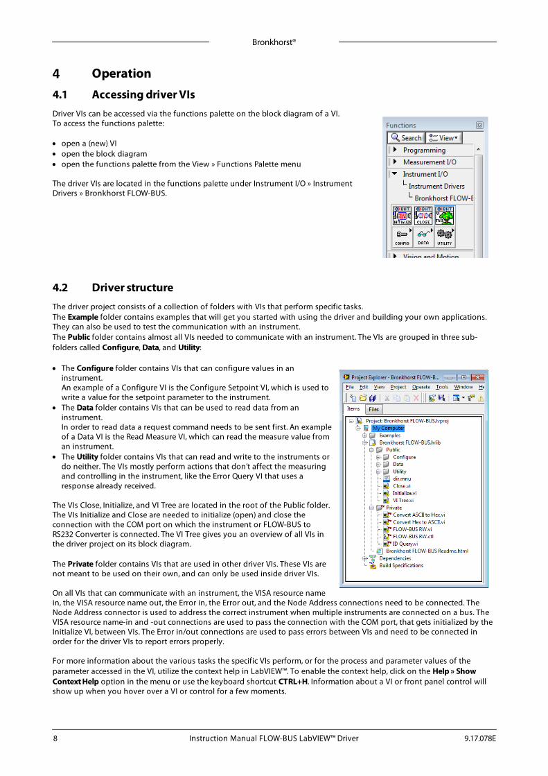
4.1 Accessing driver VIsDriver VIs can be accessed via the functions palette on the block diagram of a VI.To access the functions palette:
· open a (new) VI· open the block diagram· open the functions palette from the View » Functions Palette menu
The driver VIs are located in the functions palette under Instrument I/O » InstrumentDrivers » Bronkhorst FLOW-BUS.
4.2 Driver structureThe driver project consists of a collection of folders with VIs that perform specific tasks.The Example folder contains examples that will get you started with using the driver and building your own applications.They can also be used to test the communication with an instrument. The Public folder contains almost all VIs needed to communicate with an instrument. The VIs are grouped in three sub-folders called Configure, Data, and Utility:
· The Configure folder contains VIs that can configure values in aninstrument.An example of a Configure VI is the Configure Setpoint VI, which is used towrite a value for the setpoint parameter to the instrument.
· The Data folder contains VIs that can be used to read data from aninstrument.In order to read data a request command needs to be sent first. An exampleof a Data VI is the Read Measure VI, which can read the measure value froman instrument.
· The Utility folder contains VIs that can read and write to the instruments ordo neither. The VIs mostly perform actions that don’t affect the measuringand controlling in the instrument, like the Error Query VI that uses aresponse already received.
The VIs Close, Initialize, and VI Tree are located in the root of the Public folder. The VIs Initialize and Close are needed to initialize (open) and close theconnection with the COM port on which the instrument or FLOW-BUS toRS232 Converter is connected. The VI Tree gives you an overview of all VIs inthe driver project on its block diagram.
The Private folder contains VIs that are used in other driver VIs. These VIs arenot meant to be used on their own, and can only be used inside driver VIs.
On all VIs that can communicate with an instrument, the VISA resource namein, the VISA resource name out, the Error in, the Error out, and the Node Address connections need to be connected. TheNode Address connector is used to address the correct instrument when multiple instruments are connected on a bus. TheVISA resource name-in and -out connections are used to pass the connection with the COM port, that gets initialized by theInitialize VI, between VIs. The Error in/out connections are used to pass errors between VIs and need to be connected inorder for the driver VIs to report errors properly.
For more information about the various tasks the specific VIs perform, or for the process and parameter values of theparameter accessed in the VI, utilize the context help in LabVIEW™. To enable the context help, click on the Help » ShowContext Help option in the menu or use the keyboard shortcut CTRL+H. Information about a VI or front panel control willshow up when you hover over a VI or control for a few moments.

Bronkhorst®
Instruction Manual FLOW-BUS LabVIEW™ Driver9.17.078E 9
4.2.1 Basic application structure
The block diagram below shows an example from the example folder in the driver project. It concerns the SetpointConfigure and Read VI. This example initializes the connection, writes the setpoint (percentage) and reads back the setpoint(direct) and capacity unit from the selected instrument. After all values are read and written, the connection is closed andthe program stops.
This is just an example of a very basic application using only a few of the VIs available. Bigger and more advancedapplications can incorporate loops, case structures and events to create interactive front panels. These more advancedapplications can be used to configure instrument settings and display the data read back from the instrument. An exampleof such an application is the Bronkhorst® FLOW-BUS Instrument Control Application VI in the Examples folder.
The Initialize- and Close-VI need to be present in every application. Those two VIs are used to open the connection to theCOM port with the correct settings, and to close that connection when the application is finished. Without properinitialization communication to the instrument is not possible, and not closing the connection can result in errors whenusing the COM port in other applications.
LabVIEW™ applications can be made as complex as you need them to be. Just make sure that all VISA and Error connectionsare connected, initialized, and closed properly to insure correct operation.
To add functionality to the driver some knowledge of the driver VI structure is needed. This information is available in thenext sections. Parameter properties can be found in the parameter properties table in the RS232 interface manual(document no. 9.17.027).
4.2.2 Standard driver VI structure
The image below shows the block diagram of the Configure Counter Limit VI, which can be found in the Configure »Counter folder. This VI configures the counter limit/batch in units selected with the Configure Counter Unit VI. The value isa float in IEEE-754 32-bits single precision notation of which the default setting is 0 ln.
All driver VIs that communicate to an instrument use a FLOW-BUS RW VI. This VI is located in the Private folder thatcorresponds to the VIs function. The FLOW-BUS RW VI takes the values from the input cluster and uses these values tocreate a command string that complies with the FLOW-BUS protocol. The values needed to read from, or write to, a specificparameter can be found in the parameter properties table in the RS232 interface manual (document no. 9.17.027). In thecluster in the image above you can see all the settings to configure the counter limit. These inputs are:

Bronkhorst®
Instruction Manual FLOW-BUS LabVIEW™ Driver 9.17.078E10
Node Address The address of the instrument (node) the message is meant for.
Communication Command The type of command to send (Send parameter or Request parameter).
Process The process number of the parameter.
Parameter The parameter number of the parameter.
Data Type The data type of the parameter.
Data for [data type] The data that will be sent to the selected parameter in the selected instrument.
Constants that are not used will keep their default values.
In the image above the controls for the Node Address and the Data for Float or Long are wired into the cluster. Wiringcontrols into the cluster makes the VI interactive, as the values can now be changed from the front panel. The controls arewired into the cluster by means of the Bundle by Name function that only changes the selected values. The other values arecopied from the input cluster constants.
Most driver VIs closely resemble the pictured above. The output of the Configure Counter Limit VI does not need to beconverted before passing it into the FLOW-BUS RW VI, but there are other Configure VIs outputs which need to beconverted.
The block diagram of a Read VI looks similar to the block diagram of a Write VI. Because there is no data to be send, theparameters Data for [data type] are missing.

Bronkhorst®
Instruction Manual FLOW-BUS LabVIEW™ Driver9.17.078E 11
4.2.3 Instrument Driver Error Codes
In addition to VISA error codes, the following ‘developer defined warnings’ are implemented:
‘error out’ code Developer defined warnings
Dec Hex Error Code Description
Example 1'No error'
Example 2'Parameter type error'
1073481728 3FFC0800 00 No error
1073481729 3FFC0801 01 Process claimed
1073481730 3FFC0802 02 Command error
1073481731 3FFC0803 03 Process error
1073481732 3FFC0804 04 Parameter error
1073481733 3FFC0805 05 Parameter type error
1073481734 3FFC0806 06 Parameter value error
1073481735 3FFC0807 07 Network not active
1073481736 3FFC0808 08 Time-out start character
1073481737 3FFC0809 09 Time-out serial line
1073481738 3FFC080A 0A Hardware memory error
1073481739 3FFC080B 0B Node number error
1073481740 3FFC080C 0C General communication error
1073481741 3FFC080D 0D Read only parameter.
1073481742 3FFC080E 0E Error PC-communication
1073481743 3FFC080F 0F No RS232 connection
1073481744 3FFC0810 10 PC out of memory
1073481745 3FFC0811 11 Write only parameter
1073481746 3FFC0812 12 System configuration unknown
1073481747 3FFC0813 13 No free node address
1073481748 3FFC0814 14 Wrong interface type
1073481749 3FFC0815 15 Error serial port connection
1073481750 3FFC0816 16 Error opening communication
1073481751 3FFC0817 17 Communication error
1073481752 3FFC0818 18 Error interface bus master
1073481753 3FFC0819 19 Timeout answer
1073481754 3FFC081A 1A No start character
1073481755 3FFC081B 1B Error first digit
1073481756 3FFC081C 1C Buffer overflow in host
1073481757 3FFC081D 1D Buffer overflow
1073481758 3FFC081E 1E No answer found
1073481759 3FFC081F 1F Error closing communication
1073481760 3FFC0820 20 Synchronisation error
1073481761 3FFC0821 21 Send error
1073481762 3FFC0822 22 Protocol error
1073481763 3FFC0823 23 Buffer overflow in module
The last byte from the ‘error out’ code (hexadecimal) in Labview corresponds to the FLOWBUS-RS232 ‘STATUS MESSAGE’ number, See also chapter “STATUS MESSAGE” in manual 9.17.027

Bronkhorst®
Instruction Manual FLOW-BUS LabVIEW™ Driver 9.17.078E12
4.3 Adding driver VIThe most important part of the driver is the building of command strings and the extraction of information from theinstruments response. These functions are performed by the FLOW-BUS RW VI that can be found in the Private folder. Thischapter offers a quick overview of the inputs required to start sending and receiving data with the FLOW-BUS RW VI. Moreinformation about the FLOW-BUS RW VI can be found in the block diagram and in the context help of the VI.
4.3.1 Sending parameter
The following values have to be present in the cluster that feeds the FLOW-BUS RW VI in order to send a parameter to aninstrument.
Node Address The address of the instrument (node) the message is meant for.
Communication Command The type of command to send (send parameter with destination address and 00response).
Process The process number of the parameter.
Parameter The parameter number of the parameter.
Data Type The data type of the parameter.
Data for [data type] The data that will be sent to the instrument, different data types require to be input indifferent inputs.
All of these values can be found in the parameter properties table in the 'Instruction manual RS232 interface' (documentno. 9.17.027).
4.3.2 Requesting parameter
The following values have to be present in the cluster that feeds the FLOW-BUS RW VI in order to request a parameter froman instrument.
Node Address The address of the instrument (node) the message is meant for.
Communication Command The type of command to send (request parameter).
Process The process number of the parameter.
Parameter The parameter number of the parameter.
Data Type The data type of the parameter.
The output data depends on the Data Type. There are three data outputs, one for Character or Integer values, one for Floator Long values, and one for Strings. If the requested Character or Integer value is a negative or signed value, the outputvalue needs to be converted to a signed integer.
All of these values can be found in the parameter properties table in the 'Instruction manual RS232 interface' (documentno. 9.17.027).
To make these functions interactive, wire a front panel control to one of the cluster values by using the Bundle by Namefunction (see Standard driver VI structure).
It is important to know that not all parameters are available on all FLOW-BUS instruments. Therefore not all VIs will workon all FLOW-BUS instruments. For more details about parameters and their use see the technical documentation of yourinstrument. The Bronkhorst® software application FlowDDE also gives an overview of which parameters are available onwhich devices.

Bronkhorst®
Instruction Manual FLOW-BUS LabVIEW™ Driver9.17.078E 13
4.3.3 Example
This example shows how to create a VI that can configure the user tag of an instrument.First we need the values of the following parameters:
· Node Address· Communication Command· Process number· Parameter number· Data Type· Data
These parameters can be found in the the parameter properties table:
Parameternumber (DDE)
Parameter name Group 0 Group 1 Group 2 Processnumber
FB nr(par)
VarType
VarLength
...
115 User tag 11 113 6 c -2 ...
The next step is to enter the values in the corresponding fields of the FLOW-BUS Command Cluster. Note:· The Communication Command will be set to “send parameter with destination address and 00 response” which
corresponds to a write command with a status reply.· The combination of Var Type c and Var Length -2 indicates the data type is a string, so the Data Type will be set to String. When all settings are entered the cluster should look like this:
If this cluster is wired to the FLOW-BUS RW VI, every time the VI is executed, the same values will be sent. To make the VIinteractive, the controls of the node address and the string data can be wired into the cluster. To do this, wire the cluster tothe Bundle by Name function and select the Node Address and the Data for String as the inputs. Then create controls forthese two values and connect the output cluster to the FLOW BUS RW VI.

Bronkhorst®
Instruction Manual FLOW-BUS LabVIEW™ Driver 9.17.078E14
When everything is connected the VI can be used just like any other driver VI. The block diagram of the completed VI isshown below.
If you compare the image above to the image in Standard driver VI structure or any other driver VI, you will see a lot ofsimilarities. The only differences are the entered values, and possibly the conversion of the data to write to the instrument.Therefore the easiest way to make a new driver VI is to copy an existing one and change the necessary controls, indicatorsand values.

Bronkhorst®
Instruction Manual FLOW-BUS LabVIEW™ Driver9.17.078E 15
5 ServiceFor current information on Bronkhorst® and service addresses, please visit our website:
ü http://www.bronkhorst.com
Do you have any questions about our products? Our Sales Department will gladly assist you selecting the right product foryour application. Contact sales by e-mail:
For after-sales questions, our Customer Service Department is available with help and guidance.To contact CSD by e-mail:
No matter the time zone, our experts within the Support Group are available to answer your request immediately or ensureappropriate further action. Our experts can be reached at:
) +31 859 02 18 66
Bronkhorst High-Tech B.V.Nijverheidsstraat 1ANL-7261 AK RuurloThe Netherlands