Embed Size (px)
Citation preview

Embedded ControllersEmbedded ControllersUsing C and Arduino / 2EUsing C and Arduino / 2ELaboratory ManualLaboratory Manual
James M. FioreJames M. Fiore

Laboratory Manual for Embedded Controllers2

Laboratory Manual for
Embedded ControllersUsing C and Arduino
by
James M. Fiore
Version 2.0.2, 31 August 2016
Laboratory Manual for Embedded Controllers 3

This Laboratory Manual for Embedded Controllers Using C and Arduino, by James M. Fiore is copyrighted under the terms of a Creative Commons license:
This work is freely redistributable for non-commercial use, share-alike with attribution
Published by James M. Fiore via dissidents
For more information or feedback, contact:
James Fiore, ProfessorElectrical Engineering TechnologyMohawk Valley Community College1101 Sherman DriveUtica, NY [email protected]/jfiore
Cover art by the author
Laboratory Manual for Embedded Controllers4

IntroductionThis manual is intended for use in an introductory microprocessor or embedded controller course and is appropriate for two and four year electrical engineering technology curriculums. It utilizes the C programming language and the inexpensive, open-source Arduino hardware platform, specifically, the Arduino Uno which uses an Atmel ATmega 328P processor. The manual contains sufficient exercises for a typical 15 week course using a two to three hour practicum period. Some exercises may require more than one period (in particular, the arbitrary waveform generator). The first portion deals strictly with an introduction to the C language using standard desktop tools. Any reasonable compiler will do, and many are available free of charge. The second portion (roughly 2/3rds of the total) addresses the Arduino hardware. The Arduino system was chosen because the software is free, open-source, and multi-platform (Windows, Mac and Linux). There are several choices for hardware, most of which are quite inexpensive and open source. Although this manual focuses on the Uno board, other boards may be used with some modifications to the lab text. Interface components are fairly common such as LEDs and seven segment displays, switches, capacitors, diodes, low power resistors and switching transistors such as the 2N3904 or 2N2222. One unique element is an FSR (force sensing resistor), although the circuit may be implemented with an ordinary momentary contact pushbutton switch. Another item of interest is a small DC hobby motor.
Each exercise starts with an overview of the topics to be discussed. This usually includes some code snippets for illustration. A programming application of interest is then developed with a pseudo-code. The pseudo-code is then broken into appropriate C language code chunks. Where appropriate, hardware interface issues are discussed. Finally, the entire package is fit together.
There is a companion OER (Open Educational Resource) text to accompany this lab manual. Other lab manuals in this series include DC and AC Electrical Circuits, Computer Programming with Python, Operational Amplifiers and Linear Integrated Circuits, and Semiconductor Devices. There is also an OER text on Operational Amplifiers and Linear Integrated Circuits, and a Semiconductor Devices text is due in early 2017. Please check my web sites for the latest versions.
A Note from the AuthorThis manual is used at Mohawk Valley Community College in Utica, NY, for our ABET accredited AAS program in Electrical Engineering Technology. A key goal was to keep the student costs low so that students could buy their own development system. Having full “any time” access to the development hardware and software can be very motivating. I am indebted to my students, co-workers and the MVCC family for their support and encouragement of this project. While it would have been possible to seek a traditional publisher for this work, as a long-time supporter and contributor to freeware and shareware computer software, I have decided instead to release this using a Creative Commons non-commercial, share-alike license. I encourage others to make use of this manual for their own work and to build upon it. If you do add to this effort, I would appreciate a notification.
“Resist corporate power”
- jmf
Laboratory Manual for Embedded Controllers 5

Laboratory Manual for Embedded Controllers6

Table of Contents
1. Introduction to C Programming . . . 8
2. Using Standard I/O . . . . . 12
3. Using Conditionals . . . . . 18
4. Using Loops . . . . . . 24
5. Intro to Addresses, Pointers and Handles . . 28
6. Hello Arduino . . . . . 32
7. Arduino Digital Output . . . . 40
8. Arduino Digital Input . . . . 46
9. Arduino Analog Input . . . . 56
10.Arduino Reaction Timer . . . . 62
11.Arduino Reaction Timer Redux . . . 68
12.Arduino Analog Output via PWM . . . 76
13.Arduino Event Counter . . . . 80
14.Arduino Arbitrary Waveform Generator . . 86
Laboratory Manual for Embedded Controllers 7

1Introduction to C ProgrammingThe main objective of this initial programming exercise is to become familiar with using the programming language tools. The programs in this exercise will be fairly trivial, but serve as a springboard to later work. We will be using programs similar to the ones examined in lecture.
The precise C language package in use is not of extreme importance. Various companies will create different programming tools and although the features and fine points may differ, the basics remain the same. All C language tools need to compile C code and assemble it. Further, they need to link this assembled code with other assembled modules and libraries in order to create a finished executable program. In the simplest case, these tools will be in the form of command line utilities, i.e.; they run from a DOS prompt or shell. Ordinarily, the tools are part of a graphical integrated development environment, or IDE. IDE’s normally include a text editor. C compilers expect to work on raw text. Do not attempt to “feed” them the output of a word processor, such as .doc file. If you are using simple command line tools instead of an IDE, you will create your source files with a basic text editor such as Notepad.
C source code files utilize a “.c” extension. The output of the compiler is called an object file. It will normally have a “.o” or “.obj” extension. In the Windows world, finished executables usually have a “.exe” extension. Many IDE’s require that you create a project before you start entering your code. The project includes many attributes such as the file names used for source code (there may be several in larger projects), the appropriate libraries to link, the name of the finished executable, and so on. For simple programming chores involving small amounts of source code, this can be a bit of a pain, however, it is wonderful for larger endeavors. All the C source code of all of our exercises during this course can easily fit on a single very modestly-sized (64 MB!) USB drive. This includes the project files that can become much larger (many megabytes) than the C source. In networked labs on campus, project files and source files can be saved to the student’s network storage area. For those performing labs off-campus, it will probably be easiest to simply create new projects on your hard drive as needed.
This lab will use the Pelles C application. There is nothing magical about Pelles C though and other systems are perfectly acceptable. We shall only be using Pelles C for the introductory exercises anyway. Once we get rolling we shall shift our emphasis to the Arduino development board.
Our first exercise focuses on creating a project, editing source code, compiling and linking it, and testing it. We shall then edit it and repeat the process. We shall also look at error reporting. If you’re using command line utilities, see the note at the end of this exercise before continuing.
To begin, open the C language IDE. In Pelles C select “Start a new project” from the start pane. The new project can be one of many things. We will not be creating Windows-GUI programs, but rather DOS shell utilities, so select Win32 or Win64 Console Application (depending on your operating system) and give the project a name. To create C source code, you will need to create a new text file. Select New>>Source code under the File menu. A blank text edit window will pop open.
Laboratory Manual for Embedded Controllers8

Type the following code into the editor:
#include <stdio.h>
/* It all begins here */
int main( void ){
printf(“Hello world!\n”);}
Save this as hello.c. using File>>Save as. A dialog box will pop up asking if you want to add this file to the current project. Select “Yes”. Note that in some IDEs you will have to manually insert the file into the project (look for the appropriate menu item in such a case).
While it is possible to separately compile and link modules, most developers use the Build shortcut. This will compile and link all files as needed. In Pelles C you can select Build from either the Project menu or from the toolbar. As the project is built, you will notice messages in the status area at the bottom. If everything works out properly, it will say Building <name of project> Done. You can now check the program. Select either the Execute toolbar button or Project>>Execute from the menu bar. A small DOS shell should pop open with the message “Hello World!”. Press any key to clear this shell window and return to the IDE. You have successfully completed your first program!
Depending on the settings for your IDE, you may notice different colors on the text. In many IDEs you can specify different colors for different items such as keywords, constants, math operators, comments, and so forth. This makes reading the code a little easier.
Let’s edit the source code and have it do something else. Alter the text so that it looks like this:
#include <stdio.h>
/* Program two */
int main( void ){
int x, y;
x = 10;y = x + 20;printf(“The result is %d\n”,y);
}
Rebuild and test the resulting code. You should get a message that says “The result is 30”. Most IDE editors have the usual functionality of cut/copy/paste along with search and replace. Some also have automatic indenting, matching brace creation, and other advanced features.
OK, what happens if you make an error in your code? We shall insert a few on purpose and see what happens. Alter the program above so that it looks like this:
#include <stdio.h>
Laboratory Manual for Embedded Controllers 9

/* Program three, with errors */
int main( void ){
int x, y;
x = 10y = x + 20;printf(The result is %d\n”,y);
} Note that we have left off the trailing semi-colon on x=10; as well as the leading quote on the printf() function. Rebuild the project. This time you will receive a bunch of errors and warnings. They may differ in wording from development system to development system, but you should see something about a missing semi-colon before the y. You’ll probably also see an error concerning “The” being an undeclared identifier. You may see many warnings as well. Usually, double clicking on the error message will highlight the corresponding line in the code. Sometimes a single omission can cause the compiler to emit dozens of error messages. This is because the compiler sort of “loses track” of where it is and starts flagging perfectly good code as having errors. For this reason, if you get errors (and you will), always look at the first reported error and fix it. Do not look at the last reported error as it may lead you on a wild goose chase.
Finally, you may wish to save your code for backup. Simply select File>>Save as and choose an appropriate name. Again, C source files should use a “.c” extension. Note that you can create, read, or edit C source files without the IDE. All you need is a simple text editor. You won’t be able to compile or build it, but you can at least get some work done on an assignment without a compiler handy.
For those using a command line system (no IDE), the process is similar to what has been described, although less automatic. You will need to create your source file in a text editor. You then invoke the compiler from a DOS shell window, usually with a command something like:
cc hello.c
This will create the object file. You then invoke the linker, usually with a command like:
ln hello.exe hello.obj stdio.lib
You will have to consult your documentation from the proper commands and syntax. Once the executable is created, you test it from the shell by typing its name:
hello.exe
The appropriate output will be sent to the shell window. To edit the program, reopen the C source file in the text editor, make the changes, save the file, and then repeat compile/link commands. If errors occur, the error messages will be printed in shell window.
Laboratory Manual for Embedded Controllers10

Laboratory Manual for Embedded Controllers 11

2Using Standard I/O (Input/Output)In this exercise we will be taking a closer look at the Standard I/O functions printf() and scanf(). We shall also investigate the use of multiple user functions and prototypes. Further, we shall investigate the importance of proper program specification as well as choosing proper variable types.
This exercise involves creating a program that will assist with a simple series DC circuit analysis given component tolerances. Suppose that we have a circuit consisting of a DC voltage source and a resistor. We are interested in determining the resultant current through the circuit and the power dissipated by the resistor. This is a fairly straightforward exercise involving just Ohm’s Law and Power Law. To make this a little more interesting, we will include the effects of resistor tolerance. The program will create a table of currents and powers for the nominal, maximum and minimum allowed resistance values. This would be a very useful program for someone just starting their electrical studies. Let us keep this in mind while we design the program.
When designing a program, try to keep the user interaction as simple and as clear as possible. Also, try to structure the code to facilitate maintenance. Studies have shown that majority of programming time spent on non-trivial applications is in the area of maintenance (adding features, fixing bugs, etc.). Strive to make your code as clear as glass and include appropriate comments. Do not, however, add comments to code that even a novice would understand as that just creates clutter. Here is an example of bad commenting:
a = b + c; /* add b to c */
Duh! This comment adds nothing to the quality of the code. Similarly, use mnemonic variable names where possible. This helps to create self-commenting code. Here is an example:
x = y + z * 60;total_seconds = seconds + minutes * 60;
These two lines of code perform the same mathematical operations, but the second line gives you a hint as to what is intended. The first line would probably need a comment to make sense of it while the second line stands by itself.
Laboratory Manual for Embedded Controllers12

The ProgramHere is the (first try) specification for the program:
The program will prompt the user for a DC voltage source value, a nominal resistor value and a resistor tolerance. It will then print out the values for current and power dissipation based on the nominal, minimum and maximum acceptable values of the resistor.
Not bad, but we need to refine it. First, command line programs usually need some form of start-up message or print out of directions. Remember these are not GUI-driven programs with Help menus. Second, always prompt for input values indicating expected units. If the program expects Ohms but the user types in kilo Ohms, there’s going to be trouble. Unless there is a compelling reason not to, always use base units (Ohms versus kilo Ohms for example).
Here’s our refined specification:
The program will first give appropriate directions/explanations of use to the user. The program will prompt the user for a DC voltage source value in volts, a nominal resistor value in Ohms and a resistor tolerance in percent. It will then print out the values for current in Amps and power dissipation in Watts based on the nominal, minimum and maximum acceptable values of the resistor.
Note that we have specified tolerance as a percentage rather than as a factor. This is because the typical user would be prepared to enter 10 for 10%, not .1. You can use this specification to create a pseudo code or flow chart. Here is a possible pseudo code:
1. Print out directions for user.2. Prompt user for voltage (in Volts) and obtain value.3. Prompt user for resistance (in Ohms) and obtain value.4. Prompt user for tolerance (in percent) and obtain value.5. Determine maximum and minimum resistance values.6. Calculate currents based on the three resistances.7. Calculate powers based on the three resistances.8. Print a heading for the values.9. Print out the values.
You could of course choose an alternate algorithm or method of solution. For example, you might prefer to print the heading before the calculations and then print values following each calculation. You might prefer to change the format so that you get rows for each resistor rather than for the current and power. You might even choose an entirely different approach using loops and/or arrays. There will be upsides and downsides to each approach. Often, the question is not “Can I solve this problem?” but rather “What is the most effective way of solving this problem?” Extend a little forethought before you begin coding.
Based on the above pseudo code, the following program should fit the bill. We will refine it later. Note the use of double as we will most likely have fractional values to deal with.
Laboratory Manual for Embedded Controllers 13

#include <stdio.h>
int main( void ){
double v, tol;double rnom, rlow, rhigh;double inom, ilow, ihigh;double pnom, plow, phigh;
printf(“This program determines current and power.\n”);
printf(“Please enter the voltage source in Volts.\n”);scanf(“%lf”, &v);printf(“Please enter the nominal resistance in Ohms.\n”);scanf(“%lf”, &rnom);printf(“Please enter the resistor tolerance in percent.\n”);scanf(“%lf”, &tol);
tol = tol/100.0; /* turn tolerance into a factor */rlow = rnom – rnom*tol;rhigh = rnom + rnom*tol;inom = v/rnom;ihigh = v/rlow;ilow = v/rhigh;
pnom = v * inom;plow = v * ilow;phigh = v * ihigh;
printf(“Resistance (Ohms) Current (Amps) Power (Watts)\n”);printf(“%lf %lf %lf\n”, rnom, inom, pnom );printf(“%lf %lf %lf\n”, rhigh, ilow, plow );printf(“%lf %lf %lf\n”, rlow, ihigh, phigh );
}
A word of caution here: Note that the variable ihigh is the highest current, not the current associated with the highest resistor. This can make the print out code seem incorrect. This is a good place for some comments! Also, the initial “directions” are skimpy at best. In any case, enter and build the code above and verify that it works.
You may have noticed that there is a bit of repetition in this code in the form of calculations and printouts. It may be more convenient if we created functions to handle these. For example, we could create a function to calculate the current:
double find_current( double voltage, double resistance ){
double current;
current = voltage/resistance;return( current );
}
You could also do this in one step:
Laboratory Manual for Embedded Controllers14

double find_current( double voltage, double resistance ){
return( voltage/resistance );}
Updating the program produces the following:
#include <stdio.h>
double find_current( double voltage, double resistance ){
return( voltage/resistance );}
int main( void ){
double v, tol;double rnom, rlow, rhigh;double inom, ilow, ihigh;double pnom, plow, phigh;
printf(“This program determines current and power.\n”);
printf(“Please enter the voltage source in Volts.\n”);scanf(“%lf”, &v);printf(“Please enter the nominal resistance in Ohms.\n”);scanf(“%lf”, &rnom);printf(“Please enter the resistor tolerance in percent.\n”);scanf(“%lf”, &tol);
tol = tol/100.0; /* turn tolerance into a factor */rlow = rnom – rnom*tol;rhigh = rnom + rnom*tol;
inom = find_current( v, rnom );ihigh = find_current( v, rlow );ilow = find_current( v, rhigh );
pnom = v * inom;plow = v * ilow;phigh = v * ihigh;
printf(“Resistance (Ohms) Current (Amps) Power (Watts)\n”);printf(“%lf %lf %lf\n”, rnom, inom, pnom );printf(“%lf %lf %lf\n”, rhigh, ilow, plow );printf(“%lf %lf %lf\n”, rlow, ihigh, phigh );
}
This doesn’t seem to be much of an improvement. In fact, it just seems longer! This is true, but extend the idea a moment. What if the calculation for current involved a dozen lines of code instead of just one? This new format would save considerable code space. Note that this is not just a matter of saving some typing, but rather in saving memory used by the executable. This is particularly important when using constrained embedded systems with only a small amount of available memory.
Laboratory Manual for Embedded Controllers 15

Note that the new function was added before main(). This is not required. We could also have added it after main(), but in that case we’d have to add a function prototype so that the compiler would know what to expect when it saw the function call in main(). It would look something like this:
#include <stdio.h>
/* this is the prototype so the compiler can do type checking */
double find_current( double voltage, double resistance );
int main( void ){
....}
double find_current( double voltage, double resistance ){
return( voltage/resistance );}
Alter the program to use this new current calculation function and test it. Once this is complete, alter the program one more time to use a function to calculate the power and another to print out the three values. Use the current calculation function as a guide. Finally, consider what might go wrong with the program. What would happen if we the user entered 0 for the resistor value? How could you get around that problem?
Laboratory Manual for Embedded Controllers16

Laboratory Manual for Embedded Controllers 17

3Using ConditionalsIn this exercise we will be taking a look at using conditionals. These include the if/else construct and the switch/case construct. Conditionals are used to make a choice, that is, to split the program flow into various paths. The if/else works best with simple either/or choices while the switch/case is designed to deal with one (or possibly multiple) choice(s) from a list of fixed possibilities.
The simplest conditional is the straight if(). Depending on whether or not the item(s) to be tested evaluate to true determines if subsequent action is taken. By grouping clauses with the logical operators || and &&, complex tests may be created. if() statements may be nested as well as include processing for the test failure by using the else clause. If you need to choose a single item from a list, for example when processing a menu selection, this may be achieved through nesting in the following fashion:
if( choice == 1 ){
/* do stuff for 1 */}else{
if( choice == 2 ){
/* do stuff for 2 */}else{
if( choice == 3 ){
/* do stuff for 3 */}/* and so on */
}}
This arrangement is a bit cumbersome when choosing from a large list. Also, it is difficult to deal with a plural choice (e.g., picking items 1 and 3). For these situations the C language offers the switch/case construct. There is nothing a switch/case can do that you can’t recreate with nested if/else’s and additional code, but the former offers greater convenience as well as clearer and more compact code. The switch/case is used frequently, but ultimately, the if/else is more flexible because it is not limited to choosing from a list of numeric values. Ordinarily, numeric constants are not used in production code, as in the example above. Instead, #define’s are used for the constants in order to make the code more readable. A real-world switch/case version of the previous example might look like:
#define WALK_DOG 1
Laboratory Manual for Embedded Controllers18

#define LET_OUT_CAT 2#define COMB_WOMBAT 3
switch( choice ){
case WALK_DOG:/* c’mon poochie... */break;
case LET_OUT_CAT:/* there’s the door... */break;
case COMB_WOMBAT:/* first the shampoo... */break;
/* and so on */}
In this exercise we’re going to make use of both constructs. The program will involve the calculation of DC bias parameters for simple transistor circuits. We shall give the user a choice of three different biasing arrangements (voltage divider, two-supply emitter, and collector feedback). The program will then ask for the appropriate component values and determine the quiescent collector current and collector-emitter voltage. It will also determine whether or not the circuit is in saturation. These values will be displayed to the user.
One approach to this problem is to consider it as three little problems joined together. That is, consider what you need to do for one bias and then replicate it with appropriate changes for the other two. The three are then tied together with some simple menu processing. Here is a pseudo code:
1. Give the user appropriate directions and a list of bias choices.2. Ask the user for their bias choice.3. Branch to the appropriate routine for the chosen bias. For each bias,
a. Ask for the needed component values (resistors, power supply, beta).b. Compute Ic and Vce and determine if the circuit is in saturation.c. Display values to the user.
The appropriate equations for each bias follow. All biases use the following: Vcc is the positive supply. Re is the emitter resistor while Rc is the collector resistor. beta is the current gain (hfe). The base-emitter (Vbe) may be assumed to be .7 volts. Note that if Ic-saturation is greater than Ic, then the actual Ic is equal to Ic-saturation and Vce will be 0.
Voltage Divider: also requires R1, R2 (upper and lower divider resistors).
Vth = Vcc*R2/(R1+R2)Rth = R1*R2/(R1+R2)Ic = (Vth-Vbe)/(Re+Rth/beta)Vce = Vcc-Ic*(Re+Rc)Ic-saturation = Vcc/(Rc+Re)
Collector Feedback: also requires Rb (base resistor).
Laboratory Manual for Embedded Controllers 19

Ic = (Vcc-Vbe)/(Re+Rc+Rb/beta)Vce = Vcc-Ic*(Re+Rc)Ic-saturation = Vcc/(Rc+Re)
Two-supply Emitter: also requires Vee (negative emitter supply) and Rb (base resistor).
Ic = (Vee-Vbe)/(Re+Rb/beta)Vce = Vee+Vcc-Ic*(Re+Rc)Ic-saturation = (Vee+Vcc)/(Rc+Re)
where Vee is an absolute value in all cases.
The ProgramThe program is presented in chunks, below, in the sequence you might write it. First comes the main skeleton.
#include <stdio.h>#include <math.h>
#define VOLTAGE_DIVIDER 1#define EMITTER 2#define COLLECTOR_FEEDBACK 3#define VBE .7
int main( void ){
int choice;
give_directions();choice = get_choice();
switch( choice ){
case VOLTAGE_DIVIDER:voltage_divider();break;
case EMITTER:emitter();break;
case COLLECTOR_FEEDBACK:collector_feedback();break;
default: /* tell user they’re not so bright... */printf(“No such choice!\n”);break;
}}The first two functions might look something like this (don’t forget to add their prototypes later):
Laboratory Manual for Embedded Controllers20

void give_directions( void ){
printf(“DC Bias Q Point calculator\n\n”);printf(“These are your bias choices:\n”);printf(“1. Voltage Divider\n”);printf(“2. Two Supply Emitter\n”);printf(“3. Collector Feedback\n”);
}
int get_choice( void ){
int ch;
printf(“Enter your choice number:”);scanf(“%d”, &ch);return( ch );
}
Now it’s time to write the bias functions. Here is how the voltage_divider() function might look:
void voltage_divider( void ){
double vcc, vth, r1, r2, rth, re, rc, beta, ic, icsat, vce;
printf(“Enter collector supply in Volts”);scanf(“%lf”, &vcc);printf(“Enter current gain (beta or hfe)”);scanf(“%lf”, &beta);printf(“Please enter all resistors in Ohms\n”);printf(“Enter upper divider resistor”);scanf(“%lf”, &r1);printf(“Enter lower divider resistor”);scanf(“%lf”, &r2);printf(“Enter collector resistor”);scanf(“%lf”, &rc);printf(“Enter emitter resistor”);scanf(“%lf”, &re);
vth = vcc*r2/(r1+r2);rth = r1*r2/(r1+r2);ic = (vth-VBE)/(re+rth/beta);icsat = vcc/(rc+re);
if( ic >= icsat ){
printf(“Circuit is in saturation!\n”);printf(“Ic = %lf amps and Vce = 0 volts\n”, icsat );
}else{
Vce = vcc-ic*(re+rc);printf(“Ic = %lf amps and Vce = %lf volts\n”, ic, vce );
}}
Laboratory Manual for Embedded Controllers 21

The other two bias functions would be similar to this. A few points to note: In order to obtain the absolute value, consider using the fabs() function (floating point absolute). Another approach to the program would be make the vce, icsat, and ic variables globals and move the printout section to main() because the final comparison and printout will be the identical in all three functions. (It is also possible to have the functions return the values via pointers, avoiding the need for globals.)
Complete the other two bias functions, build, and test the program. To avoid compiler warnings, you will need to place function prototypes before main(). You could place these in a separate header file, but there are too few to bother with. To create the prototypes, simply copy and paste the function declarations and add a trailing semi-colon. For example:
#define VBE .7
void give_directions( void );int get_choice( void );/* and so forth */
void main( void ){
...
Without the prototypes, the compiler won’t “know” what the functions take as arguments nor what sort of variables they return (if any). Thus, the compiler can’t do type checking and will warn you about this. Also, the compiler will assume default argument and return types of int, so when the compiler sees the function code, it will complain that the types don’t match the default. This might seem like a pain at first, but it is a cross-checking mechanism that can prevent many software bugs.
AlterationsThis program might be useful to a student studying transistors, but it may be a little cumbersome to use. After all, the program needs to be restarted for every circuit. How would you alter the program so that it would ask whether or not the user wanted to try another circuit? In other words, the user could start the program and run it continually for 100 circuits if they so wished.
Perhaps more interestingly, what would be required so that the program could be used for homework generation? That is, the program would create appropriate circuits using new component values each time, and inform the user. It would then ask user to calculate the current and voltage by hand and enter them. The program would then determine if the user’s answers were correct (within a certain percentage to compensate for round off error). Another possibility would be to present the user with a multiple choice list of possible answers instead of having them enter precise values.
Lastly, how might you attempt to “draw” the circuits so that the components are visually identified?
Laboratory Manual for Embedded Controllers22

Laboratory Manual for Embedded Controllers 23

4Using LoopsIn this exercise we will be taking a look at using loops, or iteration. We shall also investigate a few functions in the standard library. Computers are of course ideal for repetitive calculations such as those needed to create data tables.
If a specific number of iterations are required, usually the for() loop construct is the best choice. For situations where the precise number of iterations is not known, or where the termination condition can be expressed in an easier fashion, the while() loop construct is preferred. This exercise shall focus on using the while() construct, although it is recommended that upon completion you attempt to alter the code to utilize the for() construct.
This program will be used to compute a table of values for a series R-C circuit. It will compute and display the values that might be used for Bode plot. This plot shows the gain or attenuation of a network with respect to frequency. In this example we shall use the voltage across the capacitor as the output quantity. The gain is normally displayed in decibel form (or dB for short) rather than as an ordinary factor. This program won’t draw the curve, but rather list the values so that you could draw the curve yourself.
First, the program will need to obtain the resistor and capacitor values from the user. From these it will compute and display the critical frequency, fc. The user will then be asked to specify a range of frequencies over which to compute the gain values. This will consist of a start frequency, an end frequency and the number of frequency points to calculate per decade (a decade being a factor of 10). Normally the frequencies would not be equally spaced in Hertz, but rather, equally spaced by a factor. In other words, the ratio of any two adjacent frequencies would be the same rather than the number of Hertz between them. For example, if we started at 100 Hz, finished at 1000 Hz and only wanted 2 points per decade, we wouldn’t use 100, 550, and 1000 (1000 starts a new decade, so only count the 100 and 550 as the “two points per decade”). 550 is equidistant between 100 and 1000, but the ratios are way off: It’s 5.5 times larger than the starting point but not even a factor of 2 smaller than the ending point. In fact, we want the sequence 100, 316, 1000 because the ratio of 100 to 316 is 3.16 and the ratio of 316 to 1000 is also 3.16. How do we know to use this ratio? Simple! Think of the specification “two points per decade”. You want a number that when multiplied by itself yields 10, i.e. the square root of 10 (3.16). If you wanted 5 points per decade you’d use the 5th root of 10 and so on. Here’s a pseudo-code to start with:
Laboratory Manual for Embedded Controllers24

1. Give user appropriate directions2. Obtain resistance value in Ohms and capacitance value in Farads from user.3. Compute and print critical frequency.4. Obtain start and stop frequencies (in Hz) along with number of points per decade from user.5. Print out table heading consisting of Frequency (Hz) and Gain (dB).6. Determine frequency factor based on points per decade.7. Initialize frequency to start value.8. Start a loop that continues as long as frequency is less than stop frequency.9. Compute gain in dB.10. Print out frequency and dB gain.11. Multiply frequency by frequency factor to obtain next frequency of interest.12. End of loop, and of program.
The only thing that might remain a bit fuzzy is the computation of gain and its conversion to dB. The conversion to dB is defined by the following equation:
dB = 20 * log10( gain )
The gain is basically a voltage divider between the resistor and the capacitive reactance, so let’s refine step 9:
9a. Determine capacitive reactance Xc.9b. Calculate gain based on the vector voltage divider: gain = -jXc/(R-jXc). (Reminder: The
magnitude of this is Xc/(R2 + Xc2). ) 9c. Calculate dB based on dB = 20 * log10( gain )
The math library (math.h) will come in handy for common log, roots, and so forth. The functions of interest are pow(), log10(), and sqrt().
The ProgramFirst, notice the use of #define for pi and function prototypes. The functions, though small, make the main section much more readable.
#include <stdio.h>#include <math.h>
#define M_PI 3.141592653
void give_directions( void );double find_fc( double res, double cap );double find_xc( double freq, double cap );double find_dB( double gain );
int main( void )
Laboratory Manual for Embedded Controllers 25

{double r, c, xc, gain, dB, steps;double fc, f, fstart, fstop, ffactor;
give_directions();
printf("Enter the resistance in Ohms:");scanf("%lf", &r);printf("Enter the capacitance in Farads:");scanf("%lf", &c);
fc = find_fc( r, c );
printf("\nThe critical frequency is %lf Hertz.\n\n", fc);
printf("Enter the start frequency in Hertz:");scanf("%lf", &fstart);printf("Enter the stop frequency in Hertz:");scanf("%lf", &fstop);printf("Enter the number of steps per decade to display:");scanf("%lf", &steps);
printf("Frequency (Hz)\t\t\tGain (dB)\n"); /* \t is a tab */
ffactor = pow( 10.0, 1.0/steps );
f = fstart;
while( f <= fstop ){
xc = find_xc( f, c );gain = xc/sqrt(r*r + xc*xc); /* could use pow() for square here,
but mult by self executes faster */
dB = find_dB( gain );printf("%10.1lf\t\t%10.1lf\n", f, dB ); /* %10.1lf is 10 spaces
with 1 digit after decimal */
f *= ffactor; /* shortcut for f=f*ffactor; */}
}
void give_directions( void ){
printf("Bode Table Generator\n\n");printf("This program will display dB gains for a simple R-C circuit\n");
}
double find_fc( double res, double cap ){
return( 1.0/(2.0*M_PI*res*cap) );}
double find_xc( double freq, double cap ){
return( 1.0/(2.0*M_PI*freq*cap) );}
double find_dB( double gain )
Laboratory Manual for Embedded Controllers26

{return( 20.0 * log10( gain ) );
}
Enter this program and test it for several input pairs. Consider what might go wrong with this program and how you might circumvent those problems. For example, consider what might happen if the user entered 0 for the resistor value, or a stop frequency that was less than the start frequency.
Alterations and ExtensionsThere are two useful extensions once you have completed this exercise. The first, as mentioned earlier, is to re-code the loop using the for() construct. The second alteration is to add a third column to the table that shows the phase shift at each frequency. A true Bode plot is in fact two plots: One of gain magnitude versus frequency and one of gain phase versus frequency.
Laboratory Manual for Embedded Controllers 27

5Introduction to Addresses, Pointers and HandlesAll variables and functions have an address (memory location) associated with them. This is where they "live". For multiple byte entities, this is the starting address of the memory block the item occupies. The address of any variable (with the exception of register class) can be found with the & operator. Depending on the operating system, the address will generally be contained within either 2 bytes or 4 bytes in length (8 bytes for a 64 bit OS). That is, all possible addresses in the system can be so described. If an address is placed into another variable, this other variable is said to be a pointer (i.e., it stores the address of, or "points to", the first variable). In order to take advantage of type checking and pointer math, pointers are declared by the type of item they point to, even though all pointers are themselves the same size. Thus, a pointer is properly declared as a pointer to a type char or a pointer to a type float, for example. The * operator is used to indicate that the declaration is of a pointer. For example:
int *pc;
declares a pointer to an int.
int c, *pc;
c = 12;pc = &c;
This chunk of code declares an int and a pointer to an int, assigns 12 to the int (c), and then places the address of the int (c) in the pointer (pc). The value of the item pointed to can be retrieved through the indirection operator *. Consider the following addition to the above:
printf("The value of c = %d, the address of c = %d\n", c, &c );printf("The value of pc = %d, the value pc points to = %d\n", pc, *pc );
Note that c and *pc are the same value (12). Also, note that if the value of c is changed, *pc
reflects this change. Thus, adding
c = 36;printf("New value of c = %d, the address of c = %d\n", c, &c );printf("The value of pc = %d, the value pc points to = %d\n", pc, *pc );
will show 36 for *pc as well as c, and the addresses will not have changed.
Laboratory Manual for Embedded Controllers28

Exercise one: Create a small program based on the above code and run it. Compare your results to those of your fellow lab workers. What do you notice?
What if the address of the pointer is stored in another pointer? This is called a handle. Consider the following code fragment:
int c, *pc, **ppc;
c = 12;pc = &c;ppc = &pc;
printf("pc = %d, the value pc points to = %d\n", pc, *pc );printf("ppc = %d, the value ppc points to = %d\n", ppc, *ppc );
Exercise Two: Alter your program to reflect the above. Run it and compare your results. What do you think the value **ppc is? (Try it).
Addresses can be sent as arguments to functions. This is how a function can return more than one value and is an important concept to remember. Consider the following:
int main( void ){
int a, b, c, *pc;
pc = &c;
assign_it( &a, &b, pc );
printf(“The values in main are: %d %d %d\n”, a, b, c );}
void assign_it( int *x, int *y, int *z ){
*x = 1;*y = 20;*z = 300;
}
Note that assign_it() can be called using either the address of operator (&) on an existing variable, or by passing a pointer to a variable (as in the case of &c or pc). Also, assign_it()s declaration states that it is accepting pointers to int, not plain old int.
Exercise Three: Using the above as a guide, create a program to test returning multiple values from a function.
Laboratory Manual for Embedded Controllers 29

Exercise Four: Modify the above to print out the addresses of the variables as received by assign_it(), as well as &a, &b, and pc back in main(). What does this show?
Note: If you are unsure of the size of the pointers in a given operating system, simply use the sizeof() operator. This will return the size of the given item in bytes. For example, the code fragment,
int x, *pc;
x = sizeof( pc );printf(“Pointers are %d bytes\n”, x );
may print 2 (Windows 3.1, Eeek!), 4 (Windows 95/XP, many UNIX systems) or 8 (true 64 bit operating systems). Note that pc could be a pointer to a float, double, char or anything, and it will still be the same size. This is a very important point to understand. Try using sizeof() to verify this.
Laboratory Manual for Embedded Controllers30

Laboratory Manual for Embedded Controllers 31

6Hello ArduinoInstallationOne reason the Arduino system was chosen for this course is because of its low cost. The software is free and development boards are available for under $30. If you have already installed the Arduino software on your computer or do not intend to, skip forward to the next section entitled “IDE”.
To install, first simply go to http://arduino.cc/en/Main/Software and download the current version of the software for your operating system. It is available for Windows, Mac and Linux. On Windows, the software is packed into a zip file. This will need to be unzipped with a program such as WinZip. Once unzipped, simply run the setup executable file. This will install almost all of the files needed in short order. There is only one glitch, and that involves installing the driver for your board. Once the software is loaded, plug your Arduino board into your PC via a USB A to USB B cable. In a moment Windows will inform you that it found new hardware and is looking for a driver for it. If you select to see “details”, Windows will pop up something like this (Windows 7):
The glitch is that Windows won’t be able to find the driver and you’ll be greeted with something like this:
Not to worry. You can install the driver manually. The precise process varies a little from XP to Vista to 7 but goes generally as follows. First, open the Device Manager (via Control Panel>>System>>Hardware).
Laboratory Manual for Embedded Controllers32

Scroll down to “Ports”. You should see entry like “Arduino Uno R3 (COM1)”. (You might instead find it under “Unknown Devices” instead of “Ports”.) Select this and go to the Driver tab. Click on Update/Install Driver. Browse to find your driver. It will be located in the “drivers” directory of the Arduino software install directory. For the Uno, it will be named “Arduino Uno R3.inf”. Select it and let Windows install it. If you have difficulty, a step-by-step guide is available here: http://arduino.cc/en/Guide/Windows Also, a step-by-step installation guide is available at http://www.robotc.net/wiki/ARDUINO_Installing_Drivers complete with Windows 7 pics.
IDE Once the board is installed, it’s time to open the Arduino IDE. It is fairly simple when compared to larger desktop C language development systems.
You will see a single edit space with the usual cut-paste-copy facilities. The black area below the edit space is for messages from the compiler/downloader. That is, this is where compiler errors will show up
Laboratory Manual for Embedded Controllers 33

along with status messages. The File and Edit menu content are fairly typical. The Tools menu is particularly important.
The two most important items here are Board (from which you select your particular board) and Serial Port (from which you select the COM port to which your board is connected). Failure to set these correctly will result in unsuccessful programming of your board. Note that the current board and COM port selections are printed at the lower right corner of the IDE window.
There is a simple toolbar below the menus. The first item (checkmark) is called “Verify” and compiles your code. The second item (right arrow) downloads the code to the target board. The other items open and save files.
Coding
Laboratory Manual for Embedded Controllers34

Ordinarily, all code will be contained within a single file. When you create a new project, or “sketch” in Arduino, a new directory will be created for it. Unlike ordinary C language source files, Arduino sketches utilize a “.ino” extension instead of “.c”. Further, the normal main() entry point is not used. In essence, the Arduino system has already written main() for you and it looks something like this:
void main(){
init();
setup();
while(1)loop();
}
The first function call is where various system initializations occur such as allocating and presetting timers, the ADC system, etc. This has already been written for you. The other two calls, setup() and loop(), are for you to write. setup() is your own initialization function (i.e., things you need to do just once at start-up) and loop() is the portion that will be called repeatedly. So you usually start coding with something that looks like the first figure, above.
One of the issues with embedded programming is that you don’t have a console for input and output via scanf() and printf(). Normally, an embedded program won’t need these but they are very useful when it comes to debugging a program. Without printf(), how can you insert test points in your code to check progress, values, etc? One technique is to simply flash an LED at specific points in the program. The Arduino boards include a small LED on one of the ports for this purpose. While this is useful, it is limited, so a second and more powerful technique involves two-way communication with the host computer. On the Arduino, this is done via the Serial library. The IDE includes a serial monitor under the tools menu. Selecting this will open a small window. You can use it to send data to the board or send data from the board back to the host computer.
Let’s look at an example of communicating via the Serial Monitor. First, let’s consider write data from the board back to the host. Here’s a “Hello World” program.
void setup() {
Serial.begin(9600);}
void loop() {
Serial.print("Hello World\n");delay( 1000 );
}
In the setup function we open the serial library and set the communication speed at 9600 baud (more or less standard speed for the Arduino) using the Serial.begin() function. There is a complimentary Serial.end() function should you decide that you need the particular port pins that are used for serial communication for other purposes later on. Note that all of the calls to functions in this library will start with the library’s name. The loop() functions writes our message using Serial.print() and then waits for about one second using the delay() function, the argument of which is measured in
Laboratory Manual for Embedded Controllers 35

milliseconds. Once that’s done program flow returns back to main(). Of course, main() just repeats on the loop() function so it calls it again. Our message is printed a second time, a third time and so on.
Enter the bit of code above, compile and download it to the target. Once that’s done, open the Serial Monitor and look at the output. Each second you should see the message “Hello World” printed again. That’s all the controller program does. Not too useful by itself here, but the power to print items back to the host will be very useful once we get going.
Get used to using the on-line documentation. Two good places to start are the Reference page at http://arduino.cc/en/Reference/HomePage and the Tutorial page at http://arduino.cc/en/Tutorial/HomePage The Reference page includes information on all of the operators and functions built into the Arduino system. The Tutorial gives information on programming concepts and ideas. For example, here is a copy of the on-line documentation of the Serial.print() function:
Serial.print()Description
Prints data to the serial port as human-readable ASCII text. This command can take many forms. Numbers are printed using an ASCII character for each digit. Floats are similarly printed as ASCII digits, defaulting to two decimal places. Bytes are sent as a single character. Characters and strings are sent as is. For example:
Serial.print(78) gives "78"
Serial.print(1.23456) gives "1.23"
Serial.print('N') gives "N"
Serial.print("Hello world.") gives "Hello world."
An optional second parameter specifies the base (format) to use; permitted values are BIN (binary, or base 2), OCT (octal, or base 8), DEC (decimal, or base 10), HEX (hexadecimal, or base 16). For floating point numbers, this parameter specifies the number of decimal places to use. For example:
Serial.print(78, BIN) gives "1001110"
Serial.print(78, OCT) gives "116"
Serial.print(78, DEC) gives "78"
Serial.print(78, HEX) gives "4E"
Serial.println(1.23456, 0) gives "1"
Serial.println(1.23456, 2) gives "1.23"
Serial.println(1.23456, 4) gives "1.2346"
You can pass flash-memory based strings to Serial.print() by wrapping them with F(). For example :
Serial.print(F(“Hello World”))
Laboratory Manual for Embedded Controllers36

To send a single byte, use Serial.write().
Syntax
Serial.print(val) Serial.print(val, format)
Parameters
val: the value to print - any data type
format: specifies the number base (for integral data types) or number of decimal places (for floating point types)
Returns
size_t (long): print() returns the number of bytes written, though reading that number is optional
/**** end of copied reference material ****/
The cool thing about this function is the optional second argument that allows you to specify format information. The ability to print out values in hex and binary are particularly useful, for example, when examining bit fields. Modify your program so that it appears as follows, compile, download and run it:
void setup() {
int i = 27; // try different values for this
Serial.begin(9600);
// println is just print with an added newline characterSerial.println(i, DEC);Serial.println(i, BIN);Serial.println(i, HEX);
}
void loop() {
// nothing to do here}
Less common but still useful from time to time when debugging is the ability to pass values into the running program. The Serial Monitor window includes a small data entry field at the top with an associated Send button. The Serial functions of greatest interest are Serial.available(), Serial.parseFloat() and Serial.parseInt():
Laboratory Manual for Embedded Controllers 37

Serial.available()Description
Get the number of bytes (characters) available for reading from the serial port. This is data that's already arrived and stored in the serial receive buffer (which holds 64 bytes). available() inherits from the Stream utility class.
SyntaxSerial.available()
Parametersnone
Returnsthe number of bytes available to read
Serial.parseFloat()Description
Serial.parseFloat() returns the first valid floating point number from the Serial buffer. Characters that are not digits (or the minus sign) are skipped. parseFloat() is terminated by the first character that is not a floating point number.
Serial.parseFloat() inherits from the Stream utility class.
SyntaxSerial.parseFloat()
Parametersnone
Returnsfloat
/**** end of copied reference material ****/
Serial.parseInt() is similar to Serial.parseFloat() but returns an integer rather than a floating point value. The two parsing functions examine the input string and begin by discarding non-numeral characters. Once a numeral is found, it continues to look at characters in the string until another non-numeral is found. It then translates the ASCII numeral bytes into a single integer value (or float, as the case may be). Note that it is possible to send multiple values at the same time.
Here’s an example of how they might be used to create a decimal to hex converter. Enter the following chunk of code, compile and download it.
Laboratory Manual for Embedded Controllers38
int i1, i2; // globals to hold the data
void setup() {
Serial.begin(9600); }
void loop() {
// Anything in the buffer?if (Serial.available() > 0) {
i1 = Serial.parseInt(); i2 = Serial.parseInt();
// Echo back what you got, but in hex Serial.println("In hex, that is: "); Serial.println(i1, HEX);
Serial.println(i2, HEX); }}
Once the program has been downloaded, open the Serial Monitor and enter 10 27 into the text box at the top and then hit the Send button next to it (you could also hit the Enter key on your keyboard). The result should be:
In hex, that is:A1B
You can try other values as well. If you enter only one value, i2 will come back as 0. If you enter several values, multiple returns will follow. Try them both before proceeding.
If you enter a negative value, something interesting will happen. Try typing in -1 -2. What do you see and why?
Now that you have some basic knowledge of the IDE and how to perform simple text debugging, we can turn to examining how to read from and write to external circuitry.
Laboratory Manual for Embedded Controllers 39

7Arduino Digital OutputIn this exercise we shall examine basic digital output using both the Arduino code libraries and more direct “bit twiddling”. The target of this effort will be controlling an LED, including appropriate driver circuits.
First, let’s use a modified version of the example Blink program. This blinks the on board test LED connected to Arduino pin 13 at a rate of two seconds on, one second off. We will add serial text output to verify functionality.
Type the following code into the editor:
/*MyBlinkTurns on an LED then off, repeatedly.With serial output
*/ // Pin 13 has an LED connected on most Arduino boards. Give it a name:#define LEDPIN 13
void setup() {
// initialize the digital pin as an output.pinMode( LEDPIN, OUTPUT ); // initialize serial communication at 9600 bits per second:Serial.begin( 9600 );
}
void loop() {
Serial.println("On");digitalWrite( LEDPIN, HIGH ); // turn the LED on delay(2000); // wait for 2 secs
Serial.println("Off");digitalWrite( LEDPIN, LOW ); // turn the LED off delay(1000); // wait for 1 sec
}
Compile the code and transfer it to the board. Open the Serial Monitor. You should see messages on the Serial Monitor reflecting the state of the on-board LED.
Laboratory Manual for Embedded Controllers40

The code is more or less self-explanatory but a few details may be in order. First, pin 13 on the Arduino Uno’s digital header is connected to a small surface mount LED. The pin is connected to a current limiting resistor which is connected to the LED’s anode, the cathode of which returns to ground. Thus, a high voltage turns on the LED. The setup routine sets this pin for output and establishes the serial communication system. The loop routine uses digitalWrite() to alternately send this pin high or low, thus turning the LED on and off. The delay function is used to hold the levels for a moment so that they can be seen easily with the naked eye. The delay function works well enough here but it is a simple busy-wait loop meaning that no other useful work can be done by the controller during the delay time. This is a serious limitation for more intensive programming tasks but for now it is sufficient.
Let’s move off of the internal LED to an external LED. While the AVR 328P can deliver in excess of 20 milliamps per pin, if we choose to drive several LEDs it may be better to use transistor drivers for them in order to reduce the current and power demands on the controller. The basic style follows:
NPN Driver PNP Driver
The NPN driver will saturate and turn on the LED with a high base voltage while the PNP version saturates with a low base voltage. In both cases the LED current is the saturation current which can be approximated as the supply voltage minus the LED voltage, divided by the collector resistance. For example, to achieve 10 milliamps with a 5 volt supply and a red LED (about 2 volts forward bias), the collector resistor would need to be about 300 ohms. The base resistor would be about twenty times this value resulting in a base current of about 700 microamps. This would guarantee saturation for any reasonable transistor beta. If a large number of devices are to be driven it might be wise to consider a driver IC such as the ULN2003.
Let’s modify the example above to use an external NPN driver on Arduino digital pin 8. For future reference, this corresponds to Port B, bit 0. First, wire up the driver on a protoboard using standard resistor values (a 330 and a 6.8k should do). Jump the Vcc connection to the +5V header pin on the Uno and jump the ground connection to the Uno’s GND header pin (both on the POWER side of the board). Wire the input logic connection (Vbb) to Arduino digital pin 8. Modify the code as follows:
Laboratory Manual for Embedded Controllers 41

/* External LED Blink */ #define LEDPIN 8
void setup() {
pinMode( LEDPIN, OUTPUT ); }
void loop() {
digitalWrite( LEDPIN, HIGH ); delay(2000); // wait for 2 secs
digitalWrite( LEDPIN, LOW ); delay(1000); // wait for 1 sec
}
Compile the code, transfer it and run it. You should have a nice blinking LED. Note the timing. Build the PNP driver and connect it to pin 8 in place of the NPN version (do not disassemble the NPN driver, just unhook it from the controller). Do not change the code. You should notice a difference in the on/off timing. If don’t notice a change, reconnect the NPN and look again.
Now let’s consider direct access to the hardware without using the Arduino libraries. There are two ways to do this; the first is by looking up the actual addresses for the hardware ports and registers and assigning pointer variables to them. The second method (somewhat easier) involves using the pre-defined variables for the ports and registers.
The following is a variation of the blink program using direct port access via pointers. Note that the variables for the port and data direction registers are declared and then assigned hard numerical addresses. These would vary from processor to processor so the code is not portable. That’s not desirable; however, the process does illustrate precisely what is going on with the controller and does so with a reduction in resulting assembly code. Note the usage of LEDmask. Changing the value of this allows you to access different bits of that port. Also, note the use of the bitwise OR, AND and COMPLEMENT operators (|&~) to set the appropriate bit(s) in the registers.
/* Direct Blink: Using direct bit fiddling via pointers */
// This is Port B bit 0, Arduino digital output number 8
#define LEDMASK 0x01
void setup() {
unsigned char *portDDRB;
portDDRB = (unsigned char *)0x24;
// initialize the digital pin as an output.*portDDRB |= LEDMASK;
}
Laboratory Manual for Embedded Controllers42

void loop() {
unsigned char *portB;
portB = (unsigned char *)0x25;
// turn LED on*portB |= LEDMASK;delay(2000);
// turn LED off *portB &= (~LEDMASK);
delay(1000); }
Type in the code above and connect the NPN driver to pin 8. Compile and transfer the code, and test it. It should run as before.
A better version of Direct Blink uses pre-defined variables such as PORTB. These can be defined within a header file and as such, can be adjusted across devices. This makes the code portable across a family of controllers rather than tied to a specific unit. As you might notice, the code also tends to be somewhat easier to read.
/* Direct Blink 2: Using direct bit fiddling via pre-defined variables */
// This is Port B bit 0, Arduino digital output number 8
#define LEDMASK 0x01
void setup() {
// initialize the digital pin as an output.DDRB |= LEDMASK;
}
void loop() {
// turn LED onPORTB |= LEDMASK;delay(2000);
// turn LED off PORTB &= (~LEDMASK);
delay(1000); }
Type in the code above, compile and transfer the code, and test it. It should run as before.
All versions of this program can be extended to control several output bits, each connected to something different. For example, one bit could control an LED while another bit controls a relay or power transistor that controls a motor. Using Direct Blink 2, multiple bits can be controlled with a single operation simply
Laboratory Manual for Embedded Controllers 43

by creating an appropriate bit mask. For a quick example, simply set LEDMASK to 0x21 in Direct Blink 2 to control both the external and on-board LEDs in tandem. The limitation with this approach is that each item cannot be controlled with completely different timing; all items generally will have the same timing. It is possible to break up the delay calls into smaller chunks and insert calls to turn on and off individual bits between them. This is a rather clunky method though and is neither particularly accurate nor flexible if a great many items need to be controlled. We shall examine ways around this in future work.
AssignmentCreate a program that will blink two LEDs; one red, one green, alternately. That is, when the red LED comes on, the green should turn off and when the green comes on, the red should turn off. The red should be on for two seconds and the green should be on for one second. At no time should both LEDs be on simultaneously or off simultaneously (at least not within ordinary human perception). This blinking pattern should repeat over and over: red on for two seconds, green on for one second, red on for two, green on for one, and so on.
Include your code and a proper schematic diagram with component values. It is suggested that Multisim or another schematic capture program be used to generate the schematic.
Laboratory Manual for Embedded Controllers44

Laboratory Manual for Embedded Controllers 45

8Arduino Digital InputThis exercise examines basic digital input code and hardware for the microcontroller. Typically, the controller will need to react to external true/false state changes from either a user or some other circuit. For example, a user may push a button indicating that they want to start or stop a process such as muting an audio signal or engaging an electric motor. There is no “half way” with these sorts of things; you don’t “sort of start a motor a little bit”, you either do it or don’t. The controller’s digital input pins are designed for precisely this sort of signal.
Input signals must conform to proper logic levels in order to properly trigger the controller. In the case of the Arduino Uno that means the signals must adhere to the standard 0V and 5V. The signal sources can be thought of in terms of two broad categories: active and passive. An active source would be a circuit such as a logic gate or comparator that drives the input pin to 5V or 0V. For some applications this is excessive and we can get by with something much simpler, namely the passive type. For these, an internal pull-up resistor is enabled on the input pin of the controller. The pull-up is a large value resistor tied between the power supply and the input pin. The pull-up will create a logic high at the input (i.e., the input pin is “pulled high”). To achieve a low, we connect a simple switch from the pin to ground. No other external circuitry or power is needed. Obviously, a pull-up should be disabled when using active sources.
To read the logic level at an input, two things must be done. First, the corresponding data direction register bit must be set for input or read mode (and optionally, we may also wish to engage the pull-up). Once this is done we then read the appropriate port pin bit. It is worth noting that on some microcontrollers the same register is used for both input and output (e.g., the PORTB register as used on the digital write exercise). On the Atmel AVR series (such as the ATmega 328P used on the Uno), however, two different addresses are used: PORTx for writing and PINx for reading. A common error for the new AVR programmer is to try to read from PORTB when they really want to read from PINB.
In our first example we’ll toggle an input pin with a simple SPST switch using an internal pull-up. The state will observed using the Serial Monitor. Initially we’ll do this using the Arduino libraries but we’ll also look at more generic forms.
Solder a couple wires to an SPST switch and connect them to pin 8 and ground. If you prefer, you can simply insert a wire into Arduino pin 8 and then manually insert the free end into one of the ground contacts when needed. Type the following code into the editor:
Laboratory Manual for Embedded Controllers46

/* Read Digital Input V1. Monitors Arduino pin 8 and sends value to the Serial Monitor */
void setup(){
Serial.begin(9600);pinMode(8, INPUT_PULLUP);
}
void loop(){
int i;
i = digitalRead(8);Serial.println(i);
}
This is about as basic as it gets. First we open the serial monitor and then set the data direction register for input mode with pull-up via the pinMode() function (setting the mode to just INPUT disables the pull-up). In the looping section we read the value from pin 8 and then report it back to the Serial Monitor. Compile the code and transfer it to the Arduino board. Open the Serial Monitor. You should see a series of logic highs (1) scrolling by. Now insert the free end of the wire into one of the ground headers. The Serial Monitor should now show a series of logic lows (0) scrolling by. As you connect and disconnect the wire (or throw the switch) the values should flip back and forth.
/* Read Digital Input V2. Monitors Arduino pin 8 and sends value to the Serial Monitor, generic form */
// Arduino pin 8 is bit 0 of port B, also known as port bit B.0#define BITMASK 0x01
void setup(){
Serial.begin(9600);
DDRB &= (~BITMASK); // initialize the pin as an input. PORTB |= BITMASK; // enable pull-up
}
void loop(){ int i;
i = PINB & BITMASK;Serial.println(i);
}
Compared to the original, the two calls to set the input mode are a little more work but result in noticeably less machine language code (under V1.0.4 the first version used 2726 bytes while the second used 2340 bytes as noted in the status bar of the IDE). Also note that the printed variable is the actual bit value not the idealized 1 for true and 0 for false (in this instance a 1 at bit 0 is the value 1 so it’s not immediately apparent). This is generally not a problem as any non-zero value is treated as true in the C language. As a reminder, don’t check to see if a variable is true by testing to see if it’s the same as 1. Instead, check to see if it “exists”:
Laboratory Manual for Embedded Controllers 47

if(v==1) // don’t do this to check for trueif(v) // do this insteadif(!v) // and do this to check for false
Enter the second version of the Read Digital Input program, compile it, transfer it and test it. When watching the Serial Monitor the constant scrolling can be a bit of a pain (pun intended). Currently, it’s as if the Uno is saying “switch is down, switch is still down, switch is still down” over and over. It would be more convenient if it only reported a change of state. To do this, the code will need to remember the current state for future comparison. Consider the following alteration:
/* Read Digital Input V3. Monitors Arduino pin 8 and sends value to the Serial Monitor, generic form, only reports state changes */
// Arduino pin 8 is port bit B.0#define BITMASK 0x01
int priorstate=0;
void setup(){
Serial.begin(9600);
DDRB &= (~BITMASK); // initialize the pin as an input. PORTB |= BITMASK; // enable pull-up
}
void loop(){ int state;
state = PINB & BITMASK;
if( state != priorstate ){
Serial.println(state);priorstate = state;
}}
We initialize the priorstate variable to 0 as that’s what the input pin is prior to power up and on reset. The state variable is only sent to the Serial Monitor if there has been a change of state. Edit, compile, transfer and test the new version. Note that the flurry of scrolled values is replaced by a more useful output. If you throw the switch back and forth several times while watching the Serial Monitor you might see something odd. You’ll probably notice that you get more state changes than throws of the switch. Where are these random extras coming from?
DebouncingReal world mechanical switches do not behave ideally. When a switch is thrown, the mechanical contacts bounce after the initial closure resulting in a series of make-break contacts. This might last for 10 milliseconds or more depending on the design of the switch. Examples of switch bounce are shown in Figure 8-1. The problem is that the microcontroller can read the input pin in a fraction of a millisecond,
Laboratory Manual for Embedded Controllers48

and therefore, it appears as if the switch is being thrown on and off very rapidly during this multi-millisecond stretch. In some applications this is not a problem, for example, when an LED is activated according to switch position (i.e. “up” or “depressed” lights the LED). In this instance, the bounce or chatter of the signal and the LED will not be noticed by the human eye. In contrast, we might program a button switch so that multiple pushes increase a level such as brightness or volume. In this case the chatter might cause a series of levels to be skipped over yielding an inconsistent and quirky response to user input.
Switch bounce
Figure 8-1
There are two basic ways of “debouncing” switches. The first involves software and the second involves hardware. Let’s look at a software solution first.
The key to a software debounce is to stretch out the time the switch is being examined. In other words, we want to examine the state over a long enough period of time that the bouncing settles out. For example, if we note that the state has not changed over the course of, say, ten milliseconds, we can safely assume we’re not trying to read the input during a bounce. Consider the code variant below. It looks a lot like version three but there is a new function added, get_state(). This is where all the action is.
/* Read Digital Input V4. Monitors Arduino pin 8 and sends value to the Serial Monitor, generic form, only reports state changes, with software debounce */
// new function prototypeint get_state(void);
// Arduino pin 8 is port bit B.0#define BITMASK 0x01
int priorstate=0;
void setup(){
Serial.begin(9600);
DDRB &= (~BITMASK); // initialize the pin as an input. PORTB |= BITMASK; // enable pull-up
}void loop()
Laboratory Manual for Embedded Controllers 49

{ int state;
state = get_state();
if( state != priorstate ){
Serial.println(state);priorstate = state;
}}
int get_state(void){
int priorstate, state, count=0, i=0;
priorstate = PINB & BITMASK;
while( i < 30 ){
state = PINB & BITMASK;
if( state == priorstate )count++;
else{
count = 0;priorstate = state;
}
if( count >= 10 )break;
delay(1);i++;
}return( state );
}
The idea behind this new function is to continually check the pin and not return until we have seen ten milliseconds worth of consistent values. Every time the current state is the same as the prior state we increment count. When it hits 10 we know we have achieved at least ten milliseconds of unchanging signal (due to the one millisecond delay() call at the bottom of the loop), we break out of the loop and return the pin state. If levels shift due to bounce, state and priorstate will not be the same so count is reset. If a switch is faulty, the bounce period could last a very long time and to prevent the code from “hanging up” and staying in this function forever, a maximum number of 30 iterations (at least 30 milliseconds) is instituted via the variable i.
Enter version four and save it under a new name as we’ll be coming back to version three a little later. Compile and transfer the code, and then test it using the Serial Monitor. This version should produce a nice, consistent output on the Serial Monitor without the extraneous transitions of version three. It’s also worth noting that the resultant machine code is still smaller than the original code made with the Arduino libraries in spite of greater functionality (2654 bytes versus 2726 bytes for version one).
Laboratory Manual for Embedded Controllers50

The second method to debounce a switch is via hardware. Generally, this takes the form of the switch being connected to an RC network which feeds a Schmitt Trigger. The RC network will effectively filter the chattering signal and the hysteresis of the Schmitt will take care of any lingering noise or fluctuation. Figure 8-2 is a typical example (note the switch logic is reversed due to the inverter):
RC-Schmitt Trigger debounce circuit
Figure 8-2
Typical values for this circuit would be 4.7 kΩ for R1, 470 kΩ for R2 and 100 nF for C. The RC time constant for this circuit is roughly 50 milliseconds so the Schmitt thresholds will be reached in around 200 milliseconds (less than 5 τ). This should take care of even the crankiest mechanical switch. Also, note that this is an active input signal so the input pull-up will not be needed. Let’s go back to version three (without software debounce) and make a modification to accommodate the hardware debounce:
/* Read Digital Input V5. Monitors Arduino pin 8 and sends value to the Serial Monitor, generic form, only reports state changes, requires hardware debounce to drive the input */
// Arduino pin 8 is port bit B.0#define BITMASK 0x01
int priorstate=0;
void setup(){
Serial.begin(9600);
DDRB &= (~BITMASK); // initialize the pin as an input. // pull-up code has been removed
}
Laboratory Manual for Embedded Controllers 51

void loop(){ int state;
state = PINB & BITMASK;
if( state != priorstate ){
Serial.println(state);priorstate = state;
}}
Remove the hardware switch from the board. Build the debounce circuit from Figure 8-2 and connect its output to Arduino pin 8. Compile and transfer the code. Open the Serial Monitor and test the results. It should be similar to that of version four with software debounce. Also note that the code is about 300 bytes smaller. We have effectively traded memory for hardware.
There are some nice advantages to software debounce compared to hardware debounce. First, it is very flexible in that the code can be changed to fine tune the performance. Second, there’s no associated cost for the additional hardware components or expanded board space to accommodate them. There are some disadvantages, though, including increased code memory requirements for the debouncing functions (remember, microncontrollers, unlike PCs, tend to have very modest memory capacity). Another issue is the time wasted waiting for the switch signal to settle. Ten or twenty milliseconds may not seem like a lot but in some applications it can be an eternity. Whether software or hardware debounce will be used for a particular design; indeed, whether debounce will be used at all, will depend on other system factors.
Obviously, monitoring the pin state with the Serial Monitor tool is very useful for debugging and learning how the device works but it is not a typical application so let’s move to something a little more useful. Instead of sending output to the serial monitor, let’s reflect the state using an external LED off of Arduino pin 12, i.e., bit 4 of port B. We’ll continue to use the hardware debounce circuit with the new code below:
/* Read Digital Input V6. Monitors Arduino pin 8 and reflects value to an external LED, generic form, requires hardware debounce to drive the input */
// Arduino pin 8 is port bit B.0#define BITMASK 0x01
// Place LED driver on Arduino pin 12 or port bit B.4#define LEDMASK 0x10
int priorstate=0;
void setup(){
DDRB &= (~BITMASK); // initialize the pin as an input from 74HC14DDRB |= LEDMASK; // initialize the pin as an output to the LED
}
Laboratory Manual for Embedded Controllers52

void loop(){ int state;
state = PINB & BITMASK;
if( state != priorstate ) // don’t bother if no change{
priorstate = state;
if( state )PORTB |= LEDMASK; // light LED
elsePORTB &= (~LEDMASK); // extinguish LED
}}
Build a standard LED driver circuit (NPN and PNP versions shown in Figure 8-3) and connect it to Arduino pin 12. Determine a value for Rc to achieve about 10 milliamps of LED current assuming the LED voltage is 2 volts. Set Rb to achieve a base current of around .5 milliamps.
LED Driver Circuits
Figure 8-3
Once the hardware is in place; enter, compile and transfer the code. The LED should reflect your switch position. Also, if you haven’t already noticed, look at the status bar on the editor. Because we are no longer using the Serial Monitor and its associated library, the code size has dropped to a mere 510 bytes!
Laboratory Manual for Embedded Controllers 53

AssignmentIt is not always the case that an LED would directly reflect the state of a switch. As mentioned earlier, a pushbutton might be used to toggle a device. For example, push to turn something on, push again to turn it off. Modify the existing code so that the switch toggles the state of the LED rather than having the LED indicate the position of the switch. That is, the LED should change state only on a low-to-high transition of the switch (or alternately, only on a high-to-low transition). Include your code and the accompanying schematic diagram drawn using Multisim or another schematic capture tool.
Laboratory Manual for Embedded Controllers54

Laboratory Manual for Embedded Controllers 55

9Arduino Analog InputIn this exercise we shall examine a method of obtaining analog input signals such as those generated by various continuous sensors. Continuously variable sensors might be used to measure temperature, force, acceleration, and so forth. This ability shall be combined with the digital input and output techniques already examined to produce a system that indicates an applied force via a string of LEDs; The greater the applied force to the sensor, the greater the LED indication.
Microcontrollers rely on analog to digital converters (ADCs) to obtain continuously variable input data. The ATmega 328P contains a 10 bit ADC along with a six channel multiplexer. These six lines are brought out to the Arduino Uno’s analog input header; pins A0 through A5. By default, the reference voltage for the converter is the on-board five volt DC source. This represents the maximum input level that may be digitized. The minimum level is ground or zero volts (if negative signals are needed, some form of offset bias will be required). A 10 bit converter yields 210 or 1024 discrete levels. This means that each step will be slightly less than five millivolts.
To use the ADC, a reference voltage must be set during the initialization routine. After this, whenever a value is needed, simply call the analogRead() function. The only argument to the function is the input channel desired (zero through five for the Uno). The function returns the digitized value as an integer in the range of 0 to 1023. While it is possible to go direct to the hardware registers to access the ADC, the Arduino library is fairly efficient and we will save only a few bytes, if any, by avoiding it1.
We shall start with something straightforward to illustrate how to read an analog input pin. Note that unlike the digital ports, initially setting pinMode() or a data direction register (DDRx) is not required when using the analogRead() function.
Connect the outer pins of a 10 kΩ potentiometer to the +5V and ground terminals on the Uno’s header. Connect the wiper to analog pin 0 (A0). Enter the code below, compile and transfer it to the board.
/* Read analog V1. Reads voltage off of a pot and prints the digitized value to the Serial Monitor. Range = 0->1024 */
#define ANALOG_IN_PIN 0
int prior = 0;
void setup(){ Serial.begin(9600); analogReference( DEFAULT );}
void loop()
1 See BPAnalogRead.doc for details.
Laboratory Manual for Embedded Controllers56

{int a;
a = analogRead( ANALOG_IN_PIN );
if( a != prior ){
Serial.println(a);prior = a;
}}
The code is self-explanatory. The interesting twist is that instead of simply printing the analog value, the value is compared to the previous value and only if they are different is the result printed. This saves some processing effort and speeds things up.
Open the Serial Monitor. Turn the pot shaft clockwise and counterclockwise. The values on the Serial Monitor should change as the shaft is adjusted. The values should track from 0 up to 1023 (you might be off by a count due to noise). Quite literally, you could determine the actual potentiometer wiper voltage by multiplying the printed value by the step size (5V/1024 or roughly 4.883 millivolts per step), thus achieving a very rudimentary DC voltmeter.
Force SensorLet’s replace the potentiometer with a sensor. For this exercise we shall use an FSR or force sensing resistor. An FSR is a two terminal device usually in the form of a flat film, the resistance of which depends on the applied force. With no applied force the resistance is very high, usually much greater than one megohm. With full force applied (such as a hard squeeze of the fingers) the resistance may drop to as little as 100 Ω. Remove the pot and wire one lead of the FSR to the +5V header pin and the other end to a 10 kΩ resistor. The connection point between the resistor and FSR should be wired to analog pin A0 while the free end of the resistor should go to ground. This is nothing more than a voltage divider, one leg of which is a force-dependent resistance. As force is applied, the resistance drops and therefore the connection point voltage will rise. Do not change the code. Simply note how the values in the Serial Monitor change as force is applied to the FSR: the greater the force, the greater the value. Finally, swap the positions of the resistor and FSR. Increasing force should now result in decreasing values in the Serial Monitor.
LED OutputNow that the sensor and analog input function have been verified, let’s combine this with an LED display. Instead of printing values to the Serial Monitor, we will light up a string of LEDs. This will require digital output (write) code as explored in a prior exercise. To keep the effort simple and just show “proof of concept”, we’ll light up to four LEDs. Each LED will require an appropriate transistor driver circuit (or consider a Darlington driver array such as the ULN2003 that contains seven drivers in a single IC). We shall use the bottom four bits of port B for the output signals, Arduino pins 8 through 11. Consider the code below:
/* Read analog V2. Uses FSR (lower) and 10k (to +5V) on pin A0. Lights 4 LEDs off of port B.0:3 to indicate force. Active high drivers. */
Laboratory Manual for Embedded Controllers 57

#define ANALOG_IN_PIN 0
// These are the bits to be used on port B for the LEDs#define LEDMASK0 0x01#define LEDMASK1 0x02#define LEDMASK2 0x04#define LEDMASK3 0x08#define LEDMASK (LEDMASK0 | LEDMASK1 | LEDMASK2 | LEDMASK3)
void lightLEDsBar( int a );
int prior=0;
void setup(){ Serial.begin(9600); analogReference( DEFAULT ); // set LED driver bits to output mode DDRB |= LEDMASK;}
void loop(){ int a;
a = analogRead( ANALOG_IN_PIN ); if( a != prior ) { Serial.println(a); lightLEDsBar( a ); prior = a; }}
void lightLEDsBar( int a ){
if( a > 820 ) PORTB |= LEDMASK; // light everything else { if( a > 615 ) { PORTB &= (~LEDMASK3); // extinguish top PORTB |= (LEDMASK2 | LEDMASK1 | LEDMASK0); // light everything below } else { if( a > 410 ) { PORTB &= (~(LEDMASK3 | LEDMASK2)); PORTB |= (LEDMASK1 | LEDMASK0); } else { if( a > 205 )
Laboratory Manual for Embedded Controllers58

{ PORTB &= (~(LEDMASK3 | LEDMASK2 | LEDMASK1)); PORTB |= LEDMASK0; } else PORTB &= (~LEDMASK); } } }}
Of primary interest here is the requirement to initialize DDRB for output on bits 0:3 which will be used to drive the LEDs. Separate bit masks are defined for each output pin for ease of code maintenance. A new function has been created to handle the lighting chores, lightLEDsBar(). This function will create a bar graph based on the value of the argument passed to it. As there are four LEDs, we can slice the 1024 range into five segments. If the value is below 20% (about 205) no LEDs are lit. If it’s between 20% and 40% only the lowest LED is lit. As the value increases more LEDs are lit until, at 80% or higher, all LEDs are lit. The function is little more than a big cascading if/else. In any given region first the top LEDs are unlit and then the remaining LEDs below are lit. Note that the technique above is more efficient than using the digitalWrite() function because we can set the state of several bits at once by directly accessing PORTB. In contrast, digitalWrite() would require one call for each bit/LED. The Serial Monitor code has been left in so that you can monitor the results to make sure everything is working properly.
While leaving the FSR in place, wire four LED drivers to Arduino pins 8 through 11. An LED current of 10 milliamps should be sufficient. Enter the code above, compile and transfer it. To test, simply open the Serial Monitor and press on the FSR. As the force increases, the values on the Serial Monitor should decrease and fewer LEDs should light. You can think of this as an “absence of force” meter. While this might sound backwards, it can be quite useful. There are times when we want something to be under pressure and a lack of force serves as a warning (i.e. more LEDs lit means a bigger problem).
Sometimes a string of LEDs are arranged to mimic an analog meter. In such an instance we might wish to only light a single LED rather than all of the LEDs below it. We might call this “dot mode” versus “bar mode”. Version three of the program shows dot mode with an interesting twist. Also, the Serial Monitor code has been removed so note the decrease in program size.
/* Read analog V3. Uses FSR (lower) and 10k (to +5V) on pin A0. Lights 4 LEDs off of port B.0:3 to indicate force. Dot display mode. Active high drivers. */
#define ANALOG_IN_PIN 0// These are the bits to be used on port B for the LEDs#define LEDMASK0 0x01#define LEDMASK1 0x02#define LEDMASK2 0x04#define LEDMASK3 0x08#define LEDMASK (LEDMASK0 | LEDMASK1 | LEDMASK2 | LEDMASK3)
void lightLEDsDot( int a );
int prior=0;void setup(){ analogReference( DEFAULT );
Laboratory Manual for Embedded Controllers 59

DDRB |= LEDMASK; // set LED driver bits to output mode}
void loop(){ int a;
a = analogRead( ANALOG_IN_PIN ); if( a != prior ) { lightLEDsDot( a ); prior = a; }}
int thresh[] = {820, 615, 410, 205};
void lightLEDsDot( int a ){ int *p; p = thresh; if( a > *p++ ) { PORTB &= (~(LEDMASK2 | LEDMASK1 | LEDMASK0)); // turn off bottom 3 PORTB |= (LEDMASK3); // light only topmost } else { if( a > *p++ ) { PORTB &= (~(LEDMASK3 | LEDMASK1 | LEDMASK0)); PORTB |= (LEDMASK2); } else { if( a > *p++ ) { PORTB &= (~(LEDMASK3 | LEDMASK2 | LEDMASK0)); PORTB |= LEDMASK1; } else { if( a > *p ) { PORTB &= (~(LEDMASK3 | LEDMASK2 | LEDMASK1)); PORTB |= LEDMASK0; } else PORTB &= (~LEDMASK); } } }}The Dot variant is similar to the Bar version except that all LEDs are extinguished with the exception of the single “top most” LED. You might wonder why we go to trouble of extinguishing the individual
Laboratory Manual for Embedded Controllers60

effected bits instead of just setting them all to off (ANDing with 0xf0) and then setting the desired bit on. The reason is because this might create a quick toggle on/off of the desired “top most” bit. In this application you’d probably never see the difference but there might be applications where this toggling can be a problem. In any case, the total amount of machine code generated is roughly the same either way.
The more interesting alteration of the function is that an array of values is used for the thresholds rather than fixed, hard-coded values. This makes the program much more flexible should other levels be required in the future. To use a different set of thresholds, all that needs to be done is a pointer assignment to the base of the appropriate threshold array at the start of the function. Also, note in particular the use of the post-increment operator on the pointer p. This is generally more efficient than the more obvious array indexing method.
AssignmentAlter the program so that the lighting logic is inverted, that is, increasing force should light a greater number of LEDs in bar mode and reverses the motion of dot mode. Do not alter the FSR circuit. This must be achieved via code only. Second, add a switch to Arduino pin 7 (port D.7). The position of this switch should allow the user to choose between a dot mode and bar mode display. Debouncing of this switch should not be necessary. For extra credit, add a second switch (Arduino pin 6, Port D.6) which allows the user to choose between the existing linear scale and a logarithmic scale corresponding to 6 dB per LED (i.e. halving of levels, the top most LED lighting above 512). Include your code and a proper schematic diagram with component values.
Laboratory Manual for Embedded Controllers 61

10Arduino Reaction TimerIn this exercise we shall combine digital input and output processing along with timing functions and random number generation to create a simple game. The point of the game will be to test the player’s reaction time (technically, we’ll be measuring the response time which is the sum of the reaction time plus the resulting movement time). Instead of just looking at code, this exercise also will allow us to take a step back and look at system design and simple user interface issues.
The game will give the player five tries to achieve their best reaction time. Each try will consist of activating a red warning light as a means of telling the player to get ready. Then, a second green light (i.e., “go”) will be activated between one and ten seconds later, the precise time being random between tries. Once the green light comes on, the player needs to hit a switch. The amount of time between the green light turning on and the response switch activating is the player’s reaction time. The player will be told this value and at the end of the five tries, the best result will be displayed. The game also has to guard against cheating. That is, it has to disallow a hit that simply anticipates the green light firing, in other words, “jumping the gun”.
Before we consider hardware and software, we need to have some idea of what we’re measuring. In general, how fast is human response time? It turns out that this is partly a function of the stimulus (audible cues are processed more quickly by the human brain than visual cues). Typical response times are around 160 milliseconds for an aural stimulus and 190 milliseconds for a visual stimulus, although professional athletes such as Olympic sprinters might on occasion achieve a value only 2/3rds of this2. Obviously then, our hardware and software need to be much faster if we want to achieve a decent level of accuracy. The user interface consists of four things: a red light, a green light, the player’s response switch and some means of text output. For simplicity and ease of proto-typing, we shall use the Serial Monitor for text output. If this were to become a production item, the monitor could be replaced with a dedicated LCD display. Regarding the lights, LEDs seem to be an obvious choice perhaps because of their familiarity and the one-on-one personal immediacy of the game (if several people were to respond in sync, we might need a much larger or brighter light source than an ordinary LED). There is one other item to be considered and that is the turn-on speed of the light. LEDs turn on in a fraction of a millisecond whereas incandescent lights might not reach full brightness for tens or even hundreds of milliseconds. As we might be expecting response times in the 200 millisecond region, an incandescent may not be fast enough. That is, the time delay required for it to reach full brightness might skew the results, slowing the player’s apparent (measured) response time. So, it seems that simple LEDs would be a good choice here.
The final item is the player’s switch. The player might hit the switch fairly hard because they’ll want to move their hand as fast as possible to minimize the movement time. Consequently, the switch needs to be fairly robust. It should also represent a decently sized target for the player, that is, one that is large enough that the player doesn’t also have to worry about making a very precise movement. While a simple
2 See http://en.wikipedia.org/wiki/Reaction_time
Laboratory Manual for Embedded Controllers62

momentary contact pushbutton might seem like a decent choice, an FSR might prove better. The FSR contains no moving parts and provides a large target area. It also responds nearly instantly and does not suffer from switch bounce. Interconnection is easy too: We can simply connect it between an input pin and ground, and enable the internal pull-up. Normally the FSR is a very high resistance but when pressed the value drops to maybe 100 or so Ohms. This would be in series with the pull-up that is connected to the power supply. With the FSR untouched, the voltage divider rule indicates the pin voltage will float high. When the FSR is depressed, the voltage will dive to a logic low. The only downside to the FSR is the lack of physical feedback. Many switches make a clicking sound when they are engaged. This provides auditory feedback to player so that they know that their strike has registered. We can accomplish some player feedback by lighting one or both of the LEDs at the moment the strike is sensed.
We now have an idea of the potential hardware requirements. What about the software? Obviously, previously examined techniques for digital input and output can be used to read and control the player switch and LEDs. The delay() function can be used for timing the LED flashes and the main “go” delay. Two new items are needed though: some way of generating random values (in our case, between 1000 milliseconds and 10,000 milliseconds) and some method of measuring the time between two events. Let’s consider the random number first.
Generally, digital computing devices are not good at generating truly random values because they are deterministic machines. In fact, we try to “design out” all potential randomness because we need highly predictable operation. Truly random values are in no way correlated to each other. That is, there is nothing about a string of random values that will allow you to determine the next value in the sequence. It turns out, though, that we can create pseudo-random sequences without a lot of effort. A pseudo-random sequence appears to be random but if you run the sequence long enough, it will repeat. Pseudo-random sequences may not be sufficiently random for proper scientific research efforts but they’re plenty sufficient for something like our game. While the process of deriving pseudo-random numbers is beyond the scope of this exercise, we can say that the process involves some fairly rudimentary processing, such as bit shifting, on a starting value referred to as a seed. The result of this computation is then used as input to compute the next value and so on.
The Arduino library includes a function, random(), which will return a pseduo-random long integer value. The function may also be called with upper and lower bounds to constrain the returned values as in random(30,200). The sequence itself is initiated via the randomSeed() function which takes a long integer argument. A sometimes useful effect of this is that if the seed value is the same for subsequent runs of the program, the resulting pseudo-random sequence will repeat exactly. This allows for a somewhat systematic debugging of a supposedly random feature. But this raises a problem, namely, how do we get a random number for the seed to begin with? While it’s possible to ask the user for a seed value, that opens the door to possible cheating. A better way is to use a noise voltage. By its very nature, noise is random. If we look at an analog input pin which is not connected to anything, we will see a small noise voltage. We can digitize this truly random value with the analogRead() function and use it for the seed. This voltage won’t change over a very large range, but it will change a sufficient amount to make our pseudo-random sequence to appear very random indeed.
The following code shows how the random number system works. Enter the code, compile, and transfer it, and then run it. First it will print out the noise voltage and then print out random values between 50 and 1000. After you see a sufficient number of values, hit the reset button on the board to restart the code. Do this several times. These restarts should yield different sequences. From time to time you might get the same noise voltage. If you do see this, notice that the pseudo-random number sequence will be repeated exactly.
Laboratory Manual for Embedded Controllers 63

void setup(){
long i;
Serial.begin(9600);
i=analogRead(0); // any analog channel will dorandomSeed(i);
Serial.print(“Noise voltage: ”);Serial.println(i);
}
void loop(){
long a;
a = random(50,1000);Serial.println(a);delay(2000);
}
This technique should work perfectly for our application. All we need to do is constrain the random function to 1000 to 10,000 so we can use the values directly as the millisecond argument for the delay() call used to randomize the lighting of the green “go” LED.
The second part that we need involves measuring the time delay between the lighting of the “go” LED and the player striking the FSR. Normally, if you were doing this from scratch you’d have to initialize one of the ATmega 328P’s timers and check its contents when needed. Timing events is a common need in the embedded world so the Arduino initialization routine sets up a timer for you. The instant you turn on or reset the board, this internal timer starts incrementing a register that is initialized at zero. The register is incremented by one each millisecond. This timer keeps running regardless of and independent of the main code that is running (unless the main code reprograms the timer, of course). Consequently, the register value indicates how many milliseconds have passed since the board was turned on or reset. The contents of this register may be read via the millis() function. That is, millis() returns the number of milliseconds that have transpired since the last reset/power up. After about 50 days, this register will overflow and the count will begin again. It is doubtful that any individual will want to play this game that long continuously so this should not be issue. The following code snippet will do what we need:
starttime = millis();
// Flash “go” LED // wait for response from player pressing FSR, looking at input port pin
finishtime = millis();responsetime = finishtime - starttime;
So, we can now come up with a pseudo code for the looping portion of the game:
1. Initialize best response time as a very high value (long int)2. Tell user to start game by hitting FSR pad3. Wait for the player’s start response of pressing the FSR
Laboratory Manual for Embedded Controllers64

4. Start a loop for five tries, for each try:a. Generate a random number between 1000 and 10,000b. Wait a second or two to give the user a moment to get readyc. Flash red LED one or more times quickly to indicate the start
of this tryd. Delay the random amount of milliseconds from 4.ae. Record start time millisf. Flash green “go” LED quicklyg. Wait for player’s response of pressing FSRh. Record finish time and calculate response time millisj. Flash both red and green LEDs for visual feedbackk. If response time is less than 100 msec, declare a cheat and
reset response time to a high penalty valuel. Print out the response timem. Compare response time to best time so far, resetting best to
this value if this value is smaller (i.e., better)(Loop complete)
5. Print out the best value6. Wait a moment before starting next game
A few of these steps might need further clarification or adjustment. In step 4.k, a “cheat” is declared if the response time is under 100 milliseconds. This is probably generous given the statistics noted earlier and could be adjusted to a higher value. The penalty value here could be the same as the initialization value, perhaps 10,000 or more milliseconds. After all, if it takes an otherwise normal individual more than 10 seconds to respond to the stimulus, one might surmise that they are inebriated, easily confused or need to stop texting so much.
Another item of importance is the code for steps 3 and 4.g. In essence, the code needs to “wait on” the player hitting the FSR. If the FSR is wired to an input pin utilizing an internal pull-up resistor, pressing the FSR will cause the digital input at that pin to go from high to low. (Remember, pressing the FSR creates a low resistance and the FSR is basically in series with the pull-up resistor. Therefore the voltage divider rule shows that the voltage between the two items drops to a very low value, or a logic low.) Consequently, the code can “busy wait” on that pin, breaking out when the pin goes low. We might wire up the FSR to Arduino pin 8 which is bit 0 of port B. Further, we might avoid hard coding this by using a #define:
#define FSRMASK 0x01
So the requisite bit test code looks like so:
while( PINB & FSRMASK ); // DON’T use PORTB!! Remember, for input we look at PINx and for output we use PORTx. So this loop keeps running as long as the FSR input bit is high. As soon as the player pushes on the FSR with reasonable force, the pin goes low and the loop terminates.
We can streamline our code a little more regarding steps 4.c, 4.f and 4.h which flash an LED. We might hook up the green and red LEDs to Arduino pins 6 and 7 (port D.6 and D.7) and use #defines along with a function that turns an LED on and off quickly:
Laboratory Manual for Embedded Controllers 65
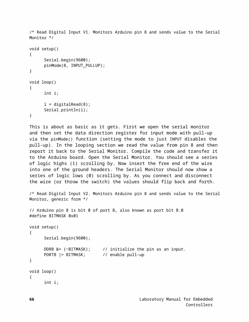
// At D.6#define GREENLED 0x40// At D.7#define REDLED 0x80// on/off time in msec#define LEDTIME 30
void FlashLED( int mask ){ PORTD |= mask; // turn on LED delay(LEDTIME); PORTD &= (~mask); // turn off LED delay(LEDTIME);}
This function would be called like so for a single quick flash:
FlashLED(GREENLED);
It could also be placed in a loop for a series of quick flashes and you could bitwise OR the mask values to flash the two LEDs simultaneously.
The last item of concern is step 6, “Wait a moment before starting next game”. Why would we include this? The reason is not obvious. Remember that the microcontroller will process everything in very short order, perhaps just a few milliseconds will transpire between the time the player hits the FSR, the finals values are printed and the loop() function terminates, only to be called again by the invisible main(). Upon re-entry, into loop(), the code tells the player to press the FSR to start the next game and then waits on the FSR bit. In that short amount of time the player will not have had a chance to lift their finger. In other words, the FSR bit is still low so the loop terminates and trial one executes immediately! To prevent this, we can either enter a small delay as the average person will not keep pressing the FSR once the response time is recorded, or we could use a separate FSR to start the game. The former seems much more straightforward.
Based on the earlier code snippets, the setup code might look something like this:
// Green LED at D.6, red at D.7, FSR at B.0, flash time in msec#define GREENLED 0x40#define REDLED 0x80#define FSRMASK 0x01#define LEDTIME 30
void setup(){ Serial.begin(9600); // set Arduino pins 6 & 7 for output to LEDs DDRD |= (GREENLED | REDLED); // Arduino pin 8 for input from FSR DDRB &= (~FSRMASK); // initialize the pin as an input. PORTB |= FSRMASK; // enable pull-up
// get seed value for random, noise voltage at pin A0 randomSeed(analogRead( 0 ));}
Laboratory Manual for Embedded Controllers66

AssignmentBased on the pseudo code presented prior, create the required loop() function for the game and test it on yourself several times. Turn in your completed code with an appropriate schematic showing all interconnections to the microcontroller. LEDs should be fed by an appropriate driver circuit to minimize controller output current. A nice modification for extra credit would be to have the program also determine and print out the total response time for each game of five tries along with the average response time. It should also indicate the number of “cheats”, if any. Note that cheats will cause the total response time and average to suffer considerably!
Laboratory Manual for Embedded Controllers 67

11Arduino Reaction Timer ReduxSometimes it’s nice to revisit a past project in order to investigate a different approach to the design. Here we’re going to rework the Reaction Timer exercise. While it was certainly useful as an instructional exercise, the obvious limitation as far as the game itself is concerned is the fact that the development board needed to be connected to a host PC running the Arduino software because it relied on the Serial Monitor for numeric output. Instead, we’re going to make a response timer that is self-contained. All it will need is a power source. There are a few different ways to achieve numeric output, perhaps the most direct is through the use of seven-segment LED displays. These devices will allow us to display all ten numerals plus a few alphabetic characters (but not the entire English alphabet unambiguously).
For ease of coding we shall dispense with the game “extras”, namely determining the best-of-five attempts, the average, and so forth; and instead focus on interfacing the displays to a basic response timer. The overall operation will be similar: The displays will flash quickly to tell the user to “get ready”, there will be a random time delay between one and ten seconds, then the displays will flash quickly as the trigger stimulus at which point the player will hit the response button (FSR) as quickly as possible. The response time will be shown on the displays for a few seconds and after a short pause, the process will repeat. The functional outline, or pseudo-code, is very similar to that of the original game. The major issue is the change of output device from Serial Monitor to seven-segment displays, both in hardware and software.
As far as the rest of the hardware is concerned, we will no longer need the signaling LEDs although we will still need the player’s switch (FSR). We do not expect reaction times faster than 100 milliseconds and it is doubtful that healthy individuals would exhibit response times slower than one second, assuming they are not distracted or operating within the constraints of some manner of trendy chemical amusement aid that performs a (hopefully) temporary self-inflicted misfiring of their neural network. Consequently, three displays should be sufficient, allowing us to render from 0 through 999 milliseconds.
Three displays will require 21 port bits if we drive them independently. This is about all we have on the Arduino Uno so it’s not a practical solution. Instead, we can time-multiplex the displays. In essence, we’ll render the hundreds digit on the left-most display for a few milliseconds, then render the tens digit on the middle display for a few milliseconds, and finally render the units digit on the right-most display for a few milliseconds. Then we’ll repeat the process. As long as we keep the overall loop time to less than about 25 milliseconds, our eye-brain processing will integrate the display over time so that it appears to be a solid and unwavering set of three digits. For this we’ll only need ten port bits; seven for the segments and three more to multiplex the individual displays. If we use common anode displays we could configure them as shown in Figure 11-1.
Laboratory Manual for Embedded Controllers68

Seven-segment display configuration
Figure 11-1
The logic for this circuit will be “active low” meaning that a logic low lights a segment/display and a logic high turns it off. Note that LED drivers are not shown here, rather, the segments are connected directly to the port pins through current limiting resistors, Rs. The Arduino will have sufficient current capacity for this if we keep the segment current to a modest level. Assuming a 5 volt supply and about 2 volts for the LEDs, a 470 Ω would keep the currents at around 6 or 7 milliamps per segment. This would be sufficient for indoor use. The individual displays are enabled through the use of the PNP drivers. A logic low on their base resistors will place them into saturation, enabling current flow to the display. For this application, a small signal PNP such as the 2N3906 will suffice. Having all segments lit will draw about 50 milliamps through the collector. Therefore, a base resistor value in the low single digit kΩ range should work well, yielding a base current of a few milliamps.
Practically speaking, it would be easiest to dedicate port D to the segments (D.1:7, Arduino pins 1-7). This does mean that we’ll lose the ability to use the Serial Monitor (it uses D.0:1) but that shouldn’t be a problem. We can use B.0:2 (Arduino pins 8-10) for the digit multiplexers and B.3 (pin 11) for the FSR. Some #defines would be good for these. We’ll also need an array of bit patterns for the displays:
Laboratory Manual for Embedded Controllers 69

// Port B.0:2 for 7 segment mux#define DIGIT1 0x01#define DIGIT10 0x02#define DIGIT100 0x04#define DIGIT111 0x07
#define FSRMASK 0x08
unsigned char numeral[]={ //ABCDEFG,dp 0b00000011, // 0 0b10011111, // 1 0b00100101, // 2 0b00001101, // 3 0b10011001, 0b01001001, 0b01000001, 0b00011111, 0b00000001, 0b00011001, // 9 0b11111111, // blank 0b01100001, // E 0b01110011, // r 0b00001001, // g 0b00111001 // o };
#define LETTER_BLANK 10#define LETTER_E 11#define LETTER_R 12#define LETTER_G 13#define LETTER_O 14#define MSG_GO -1#define MSG_ERR -2
The variable numeral is an array defined using binary values. Each bit signifies a segment with the MSB being segment A (top horizontal) and the LSB being the decimal point (unused here). For example, the numeral “0” requires every segment except G (the middle horizontal bar) and the decimal point to be lit. Because our circuit is active low, we put a 0 at each bit that will be lit. We repeat this process for the remaining nine numerals. We also add a few special characters, namely blank and the letters E, r, g and o. We’ll use the first two to spell “Err” for error (what we used to call a “cheat”) and the second two to spell “go” which will take the place of the former green “go” LED. We have also defined a couple of MSG variables to be examined in a moment.
Given these definitions, let’s take a look at how the setup() function has changed. We need to change which pins are being used but we still need the seed value for random(). Note that since we are setting all bit of port D to output mode, we can just blast in 0xff instead of bitwise ORing the specific bits. It is also important that we set the mux bits (DIGIT111) of port B high. As the port D pins are also low by default, all of the displays will light up when the board is reset. This will cause a considerable current draw through the microcontroller. Setting the mux bits high ensures that everything will be off (not enabled).
Laboratory Manual for Embedded Controllers70

void setup(){ // set Arduino pins 0 through 7 (port D.0:7) for output displays DDRD = 0xff;
// set Arduino pins 8 through 10 (port B.0:2) for output to mux LEDs DDRB |= DIGIT111;
// Displays are active low so turn them off initially PORTB |= DIGIT111;
// Arduino pin 11, port B.3 for input from FSR DDRB &= (~FSRMASK); // initialize the pin as an input. PORTB |= FSRMASK; // enable pull-up
// get seed value for random- noise voltage at pin A0 randomSeed(analogRead( 0 ));}
Here is our main loop, slightly altered. Compare it line-by-line to the original version and note any similarities and alterations. The comments alone should provide sufficient detail. The most obvious changes are the removal of the Serial Monitor code and the inclusion of a new function called DisplayValue() which will be discussed shortly.
void loop(){ unsigned long starttime, finishtime; int i, j, nettime; long a;
for(i=0;i<5;i++) { a = random(1000, 10000);
// wait a couple of seconds to start this round delay(2000); // flash display a few times to tell player to get ready for(j=0;j<5;j++) { DisplayValue( 888, 100 ); delay(100); }
// delay random amount delay(a);
// flash LED for real starttime = millis(); DisplayValue( MSG_GO, 50 ); // wait for response, pressing FSR makes a low while( PINB & FSRMASK );
Laboratory Manual for Embedded Controllers 71

finishtime = millis(); nettime = finishtime - starttime;
// check for cheat if( nettime < 100 ) nettime = MSG_ERR;
DisplayValue( nettime, 3000 ); }}
Functionally, DisplayValue() is fairly straight-forward to use. The first argument is the number to be displayed, from 0 through 999. The second value is the duration of the display in milliseconds. So DisplayValue( 888, 100 ) means “display the number 888 for 100 milliseconds”. This particular line makes the “get ready” flash. DisplayValue() also allows for a few special values. These are encoded as negative values. A negative response time is impossible, of course, without some form of time travel ability. If the value is set to MSG_ERR then the display shows “Err”. If the value is set to MSG_GO then the display shows “go”. Thus the former flashing of the green “go” LED is replaced with DisplayValue( MSG_GO, 50 ), producing the “go” message for 50 milliseconds.
The first thing the function should do is validate the value passed to it. It needs to check for the special message codes as well as values out of range. Whatever value is passed, we must derive three new values, namely the indices for the numeral array. These will be stored in the variables h, t and u which stand for hundreds place, tens place and units place. The special cases should be checked first. Beyond that the value needs to be broken down into its individual digits through the use of integer divides and mods. Successive integer divisions by 10 will effectively shift the number down a place while mod by 10 will leave the remainder. Think of a three digit number at random and verify that the logic works.
void DisplayValue( int v, int msec ){ unsigned char i, h, t, u;
if( (v <= MSG_ERR) || (v > 999) ) // error code { h = LETTER_E; t = u = LETTER_R; } else { if( v == MSG_GO ) { h = LETTER_G; t = LETTER_O; u = LETTER_BLANK; } else { u = v%10; v = v/10; t = v%10; h = v/10; } }
Laboratory Manual for Embedded Controllers72

At this point we need to turn the requested duration into loop iterations. As coded, each iteration lasts about 15 milliseconds given that each digit is illuminated for 5 milliseconds. A simple division will suffice although we may wish to guard against someone accidentally requesting just a few milliseconds (which would yield zero).
// turn millisecs into loop iterations msec = msec/15; if( msec < 1 ) msec = 1;
We now create a loop that will roughly yield the requested duration with 15 millisecond resolution. Inside the loop, first we clear all of the displays. Then we enable the desired display and blast in the code for the numeral. Note that by entering the binary values into the array in ascending order we can just use the computed digit value as the index into the array. We don’t need to translate the desired numeral into the appropriate index. A little forethought can save coding effort and memory space. Each digit is held for 5 milliseconds. At the close of the function we turn off the display.
// display the value for the specified time for( i=0; i<msec; i++ ) { // clear all displays then activate the desired digit PORTB |= DIGIT111; PORTD = numeral[h]; PORTB &= ~DIGIT100; delay(5);
PORTB |= DIGIT111; PORTD = numeral[t]; PORTB &= ~DIGIT10; delay(5);
PORTB |= DIGIT111; PORTD = numeral[u]; PORTB &= ~DIGIT1; delay(5); } // clear display PORTB |= DIGIT111;
Laboratory Manual for Embedded Controllers 73

AssignmentThis exercise involves a considerable amount of wiring and a non-trivial amount of code. There are a lot of things that can go wrong if you just dive in and try to do everything at once. For example, if a segment or an entire digit fails to light, how do know whether the problem is in the hardware or in the software? Debugging both simultaneously is no minor task. It is better to make sure that chunks of the code work as expected first, then build on that. For example, you might just code the chunk that lights one display then expand to a multiplexed display. Consider something like this:
// Port B.0:2 for 7 segment mux#define DIGIT1 0x01#define DIGIT10 0x02#define DIGIT100 0x04#define DIGIT111 0x07
#define FSRMASK 0x08
unsigned char numeral[]={ //ABCDEFG,dp 0b00000011, // 0 0b10011111, // 1 0b00100101, // 2 0b00001101, // 3 0b10011001, 0b01001001, 0b01000001, 0b00011111, 0b00000001, 0b00011001, // 9 0b11111111, // blank 0b01100001, // E 0b01110011, // r 0b00001001, // g 0b00111001 // o };
#define LETTER_BLANK 10#define LETTER_E 11#define LETTER_R 12#define LETTER_G 13#define LETTER_O 14#define MSG_ERR -2
void loop(){ // try a bunch of different things... DisplayValue(123); DisplayValue(456); DisplayValue(12); DisplayValue(3); DisplayValue(100); DisplayValue(-2); DisplayValue(50);}
Laboratory Manual for Embedded Controllers74

void DisplayValue( int v ){ unsigned char i, h, t, u; // hundreds, tens, units
if( (v <= MSG_ERR) || (v > 999) ) // error code { h = LETTER_E; t = u = LETTER_R; } else { u = v%10; v = v/10; t = v%10; h = v/10; }
// display the value for approx 1 sec (66x15msec) for( i=0; i<66; i++ ) { // clear all displays then activate the desired digit PORTB |= DIGIT111; PORTD = numeral[h]; PORTB &= ~DIGIT100; delay(5);
PORTB |= DIGIT111; PORTD = numeral[t]; PORTB &= ~DIGIT10; delay(5);
PORTB |= DIGIT111; PORTD = numeral[u]; PORTB &= ~DIGIT1; delay(5); } // clear display PORTB |= DIGIT111;}
Once you have the circuit working, try it for real! Turn in your code and a completed schematic. Also, comment on what code and hardware alterations would be needed (if any) if common cathode displays were used instead of common anode.
Laboratory Manual for Embedded Controllers 75

12Arduino Analog Output via PWMIn this exercise we shall examine analog output through the use of PWM or pulse width modulation. PWM is a method to produce analog signals using a digital output rather than a true continuously variable output. While some microcontrollers and boards have true DACs built-in (the Arduino Due being one example), most do not. Therefore, a digital pulse output is used with a variable duty cycle. The “analog” signal basically is the “area under the curve”. If you thought of averaging the pulse train with a low pass filter, a small duty cycle would achieve a low value and a high duty cycle would achieve a high value. Some loads may need proper filtering of the pulse train but some do not. In this exercise we shall begin by examining a simple LED.
It is easy enough to flash an LED on and off. Consider the code below:
/* PWM V1 Manual LED brightness test */
#define LEDBIT 0x40
// on/off time in msec#define LEDONTIME 300#define LEDOFFTIME 300
void setup(){
// set Arduino pin 6 for output to an LEDDDRD |= LEDBIT;
}
void loop(){
PORTD |= LEDBIT; // turn on LEDdelay(LEDONTIME);
PORTD &= (~LEDBIT); // turn off LEDdelay(LEDOFFTIME);
}
In this example the LED flashes on and off 300 milliseconds each for a total cycle time of 600 milliseconds. Attach a standard NPN LED driver circuit to power, ground and Arduino pin 6. Enter the code, compile, transfer and run it to verify. Reduce the on/off times to 30 milliseconds each and repeat. The LED should flash much faster. Reduce the on/off times to 5 milliseconds each and repeat. A curious thing happens. The LED doesn’t seem to be flashing anymore; rather it just seems dimmer. Once the timing drops below about 20 milliseconds, the human eye integrates the visual input over time and we no longer see discrete flashes3. Instead, we see the average illumination. Since the LED is only on for half 3 If this was not the case we would not get the impression of continuous motion while watching TV or movies which use frame rates of 30 and 24 frames per second respectively. The frames “blur together” in our brains creating the
Laboratory Manual for Embedded Controllers76

the total time, it appears dimmer than a single long flash. You can verify this by changing the on time to 1 millisecond and the off time to 9 milliseconds, still achieving a 10 millisecond cycle time. The LED should appear quite dim as the average level is now only 10 percent of the maximum.
Instead of adjusting the timing manually, we can use the library function analogWrite() on one of the PWM capable output pins (these are marked with a “~” next to the header). Fortunately, pin 6 is PWM capable so all we need is a little change to the code:
/* PWM V2 LED brightness using analogWrite */
#define LEDPIN 6
// brightness 0 to 255#define LEDBRIGHTNESS 230
void setup(){}
void loop(){
analogWrite(LEDPIN,LEDBRIGHTNESS);}
Note that pin 6 does not need to be set for output mode as this is done automatically by the analogWrite() function (see BPanalogWrite.doc for details). If you placed an oscilloscope at pin 6 you’d see a square wave at about 490 Hz with 90 percent duty cycle. Note that the LEDBRIGHTESS parameter can be replaced with the results from an analogRead() call. So, we can connect a potentiometer to an analog input pin and read its voltage which will range from 0 to 1023. We then scale this range onto the 0 to 255 (unsigned char) input of analogWrite() to create a dimmer. The scaling can be performed using the Arduino library function map(). The template is:
result = map(value, fromLow, fromHigh, toLow, toHigh);
In our case we’d use:
result = map(value, 0, 1023, 0, 255);
To continue, wire a 10 kΩ potentiometer between power and ground, connecting the wiper arm to Arduino pin A0. Enter the code below, compile and transfer it.
/* PWM V3 LED dimmer using analogWrite and potentiometer */
#define ANALOG_IN_PIN 0#define LEDPIN 6
void setup(){
analogReference( DEFAULT );}
illusion of continuous motion.
Laboratory Manual for Embedded Controllers 77

void loop(){
int a;
a = analogRead( ANALOG_IN_PIN );
a = map(a,0,1023,0,255);analogWrite(LEDPIN,a);
}
LEDs are all well and good but we might wish to control something a little more interesting such as a motor. Obviously, our LED driver circuit will be insufficient for any decently sized motor but it will do just fine for a small 10-15 milliamp (unloaded) DC hobby motor given some minor modifications. An example is seen in Figure 11-1.
Figure 11-1
Motor Controller
First note that a higher supply is required. In this case, 15 VDC would be appropriate. R1 would need to be about 6.8k to guarantee transistor turn-on and C1 needs to be about 100 nF. D1 should be a 1N4002 rectifier. It is used to prevent, or snub, a sudden voltage spike caused by the motor’s inductance when the transistor switches state between saturation and cutoff4. Build the circuit of Figure 11-1 and connect it to Arduino pin 6 in place of the LED driver. (You might want to keep the LED driver wired up for upcoming modifications and additions.) There is no need to change the code. Once the motor circuit is connected, its speed should now be controlled by the potentiometer.
4 Remember, the current through an inductor cannot change instantaneously. The sudden transistor switching would result in a large inductor reverse voltage which would in turn cause a large voltage spike across the transistor due to KVL. So the diode is placed there to limit said voltage and protect the devices. See: http://en.wikipedia.org/wiki/Flyback_diode
Laboratory Manual for Embedded Controllers78

AssignmentSometimes we need a form of visual feedback regarding the control variable; in other words, some manner of readout. In this case, we can make a simple “LED bar” to indicate the motor speed; the faster the speed, the wider the bar. There is no need to re-invent the wheel as we’ve done this before. Consider adapting the lightLEDsBar() function from the Arduino Analog Input exercise. It will require four LED drivers connected to port B.
Finally, let’s consider setting the motor speed in accordance to some environmental variable such as temperature or light level instead of using a manually controlled potentiometer. The potentiometer can be replaced with a simple sensor such as the LM34 for temperature or a resistor and photoresistor (CdS cell) voltage divider to sense light levels. It will be relatively easy and safe to create extreme changes in light level using a flashlight and a finger (to cover and block the light). The range of the temperature sensor voltage will be comparatively narrow and so a different range of mapping will probably be in order. You may also wish to mount the temperature sensor away from the other circuit elements in order to isolate them from excessive heat and cold. No open flames should be used in lab to create heat!
Include your code and a proper schematic, as usual, along with a description of how you tested the result.
Laboratory Manual for Embedded Controllers 79

13Arduino Event Counteror Revenge of the Son of the Reaction Timer ReduxOften it seems we need our microcontroller to be doing several things at once such as monitoring inputs while controlling changing outputs. A single controller cannot do this in the literal sense but it can operate so quickly that it appears to be doing several things simultaneously. Sometimes, though, this can get quite complicated if polling or busy-wait style code is used. For example, consider the operation of multiplexing several seven segment displays. Unlike a simple LED which merely requires us to set or clear a port bit, the multiplexed displays need constant attention. In the Reaction Timer Redux exercise the displays required 15 milliseconds per rendering; 5 milliseconds for each of the 3 displays. If we wanted to display the value for a few seconds we simply looped around that code. Although this worked well for that application, such is not always the case. Consider the case of an event counter. This is a device that counts things and displays the current value. It might be used on an assembly line to keep track of the number of items that have passed by, perhaps via the item triggering a mechanical, photo-electric, magnetic or other kind of switch. We would like this device to present a display of the current count at all times yet we also need to be constantly checking the item switch. How do we do both? In the case of the Reaction Timer we could add code within the display loop that checks the item switch but if the switch activates and deactivates in under 15 milliseconds we could miss it while the displays are being written to. Fortunately, there is a nice solution to this problem.
We Interrupt Our Regularly Scheduled Code…The solution is the use of an interrupt. Think of an interrupt as a scheme whereby a special bit of code called an interrupt handler or interrupt service routine (ISR) is triggered to run under special conditions. The execution of the existing code is suspended until the ISR is done. The interrupt can be triggered by either software or hardware events. A typical example would be to have the interrupt triggered by a signal change on an input port pin. Most microcontrollers have many different levels of interrupts and these can be sorted by importance. That is, some events can take precedence over other events. This means that it may be possible to have one ISR interrupted by a higher priority interrupt. Generally, ISRs should be short, quickly executing chunks of code so as to not clog-up the operation of the main code. In the case of our event counter, the item switch could be connected to an input pin that triggers an interrupt. The ISR would do nothing more than increment a global variable that keeps track of the item count. The main body of the code would then periodically check this global and respond accordingly (in this case, updating the display). We can think of the ISR scheme as “running in the background” constantly checking the input pin. This frees us from having to sprinkle port checking code throughout the main body of the program.
Ordinarily, none of the available interrupts are active with the exception of the system reset. These have to be enabled individually before they can be used. The development system defines a name for each interrupt routine so all we have to do is enable the proper bit(s) in the interrupt control register(s) and fill out the code for the ISR.
Laboratory Manual for Embedded Controllers80

For the event counter, we’re going to reuse a considerable amount of code and hardware from the Reaction Timer Redux exercise, most notably the seven segment displays and multiplexing code. The player’s switch will be traded for the event counting switch. We shall make use of the ATmega 328P’s pin change interrupt (PCINT) capability. When programmed, each of the input port pins can trigger an interrupt when its input signal changes from high to low or low to high. These are arranged into banks which correspond to the ports, for example bank 0 corresponds to port B. Each bank has an ISR associated with it. The bank 0 ISR is called PCINT0_vect. This stands for “Pin Change Interrupt Bank 0 Vector” (technically, a vector is a function address so this is really the starting address of the interrupt service routine). Each of the pins of a particular port is activated through its own interrupt bit. For bank 0, these bits are PCINT0 through PCINT7. So, if port pins 0 and 1 are enabled for interrupts (via PCINT0 and PCINT1), a change on either of their pins will generate the bank 0 pin change interrupt and cause the PCINT0_vect ISR to execute. Once the ISR is done, normal execution of the main code will continue where it left off.
Before we look at hardware let’s consider some code. As mentioned, we can modify the existing Reaction Timer Redux code. We will no longer need the special “go” message so we can delete some items from the numeral array. Other modifications will be minimal if we keep the wiring the same. We’ll use the generic term “sensor” in place of the former FSR as we have yet to determine how the event counting switch will be implemented. Note that having some documentation inside the original code as to how the circuit is wired saves us from re-inventing the wheel. All good programmers, technicians and engineers do this!
/* Event counter with common anode 7 segment displays X 3. Displays off of D1:7 (segment a=7), Mux off of B0:2 (hundreds on B.2), w/ PNP drivers. Sensor on B.3. Values > 999 show up as "Err" ALL SEGMENTS AND MUX ACTIVE LOW */
// Port B.0:2 for 7 segment mux#define DIGIT1 0x01#define DIGIT10 0x02#define DIGIT100 0x04#define DIGIT111 0x07
#define SENSORMASK 0x08
unsigned char numeral[]={ //ABCDEFG,dp 0b00000011, // 0 0b10011111, // 1 0b00100101, // 2 0b00001101, // 3 0b10011001, 0b01001001, 0b01000001, 0b00011111, 0b00000001, 0b00011001, // 9 0b11111111, // blank 0b01100001, // E 0b01110011 // r };
#define LETTER_BLANK 10#define LETTER_E 11#define LETTER_R 12
Laboratory Manual for Embedded Controllers 81

At this point we need to declare the afore-mentioned global variable and modify the setup() routine.
unsigned int g_count = 0;
void setup(){ // set Arduino pins 0-7, port D.0:7, for output to 7 segment LEDs DDRD = 0xff;
// set Arduino pins 8-10, port B.0:2, for output to mux 7 segment LEDs DDRB |= DIGIT111;
// Displays are active low so turn them off initially PORTB |= DIGIT111;
// Arduino pin 11, port B.3 for input from sensor DDRB &= (~SENSORMASK); // initialize the pin as an input. PORTB |= SENSORMASK; // enable pull-up
// enable pin change interrupt bank 0 bitSet(PCICR,PCIE0);
// enable pin change interrupt on port B.3 bitSet(PCMSK0,PCINT3);}
The last two lines of the code above are particularly important. The first line enables the pin change bank 0 interrupt (bit PCIE0 or Pin Change Interrupt Enable bank 0) in the Pin Change Interrupt Control Register (PCICR). The second line then specifies which pin(s) in bank 0 will be used (Pin Change INTerrupt pin 3 or PCINT3) in the Pin Change MaSK for bank 0 (PCMSK0) register.
Once enabled, we now need to write the ISR itself. As mentioned, this routine already has a name (PCINT0_vect) and all it needs to do is increment the global count variable.
/* This is the bank 0 interrupt handler. It triggers on any change to the appropriate pin(s) of bank 0 (port B), either H->L or L->H. */
ISR(PCINT0_vect){ // increment only on sensor going low to avoid double counting if( !(PINB & SENSORMASK) ) g_count++;}
The former loop() function can be tossed. In its place we use the contents of the former DisplayValue() function that controlled the displays multiplexing. Unlike the original, this does not render the display for a specified time. Rather, it does a single scan of the three displays for a total of 15 milliseconds. loop() will then be called again and the process repeats.
At the start, the contents of the global count variable are copied to a local variable which is then taken apart to determine the indices into the numeral array as before. Note a minor refinement, namely the snippet of code added to “blank” leading zeros. A question might remain though, and that is, why bother
Laboratory Manual for Embedded Controllers82

to make a local copy of the global variable? The reason is because an interrupt can happen at any time. That means that partway through the h, t, u index code an interrupt might occur and the global variable will change. If this happens the computed indices will be incorrect because the code will be operating on two (or possible more) different values. If we make a local copy this won’t happen. Only the global will change and the display will be updated appropriately the next time loop() is called.
void loop(){ unsigned int v; unsigned char h, t, u; // hundreds, tens, units
// grab a local in case another interrupt comes by v = g_count;
if( v > 999 ) // error code { h = LETTER_E; t = u = LETTER_R; } else { u = v%10; v = v/10; t = v%10; h = v/10; // blank leading zeros if( !h ) { h = LETTER_BLANK; if( !t ) t = LETTER_BLANK; } }
// clear all displays then activate the desired digit PORTB |= DIGIT111; PORTD = numeral[h]; PORTB &= ~DIGIT100; delay(5);
PORTB |= DIGIT111; PORTD = numeral[t]; PORTB &= ~DIGIT10; delay(5);
PORTB |= DIGIT111; PORTD = numeral[u]; PORTB &= ~DIGIT1; delay(5); // clear display PORTB |= DIGIT111;}
Laboratory Manual for Embedded Controllers 83

At this point we have some workable code. If the earlier hardware is not still in place, rewire it. Enter the code above, compile and transfer it. Each press of the player button should show an increment on the display. Note: If the switch was not debounced you might get an extra count or two on random presses.
The SwitchThe trick now is to implement an appropriate switch to count the items or events in question. All it needs to do is make or break contact, or produce a high-low-high voltage transition. Let’s assume we’re counting items passing by on a conveyor belt. The implementation will depend on the items themselves. Are they all the same size and orientation? How heavy are they? Are they randomly placed and timed? In some cases a simple mechanical spring-mounted “flip” switch can be used: The item brushes up against the switch and pushes it to the side, activating it. The spring then restores the switch to the off position to await the next item. If the items are small, irregularly positioned or shaped, this technique may have difficulty. Another approach is to use a photo-electric scheme. Here, a beam of visible or infrared light is shown across the conveyor belt. Opposite it is a detection device. When an item passes by, the beam is broken and a signal generated. This scheme will work with oddly shaped or placed items as well as very light items as no physical contact is made. Not everything will work with this, though. Possible examples of difficult items include aquariums and thinly sliced chunks of Swiss cheese (really, an oddly shaped device with gaps might cause multiple triggers).
Mechanical switching will require some fabrication but the idea is straight-forward enough. For photo-electric, there are a few options. One possibility is the use of a light dependent resistor or CdS cell and a strong light source. The CdS cell will exhibit high resistance under low light and the resistance will decrease as light levels increase. The CdS cell could be connected directly to an input port pin with the internal pull-up resistor enabled. A major challenge here is the ambient light. Another possibility is an infrared emitter-detector pair (IR LED plus IR phototransistor). This would require a little more circuitry but would tend to be less sensitive to ambient light conditions.
Alignment of photo-electric devices and their separation distance can be critical to proper and consistent triggering. For ease of testing in lab, it is best to focus on “proof of concept”, keeping the devices only an inch or two apart and simulating the items to be counted by passing a black card between the sensor/detector pair.
AssignmentRemove the former player switch and insert your new item counting switch in its place. Also, add a second switch that will reset the item count back to zero (it is not acceptable to simply use the board reset switch). Include a description, rationale and schematic of the item counting switch.
Laboratory Manual for Embedded Controllers84

Laboratory Manual for Embedded Controllers 85

14Arduino Arbitrary Waveform GeneratorThis exercise combines much of the preceding work, namely sensing digital input, creating digital output, timing, etc. A major new element is producing analog output voltages without resorting to pulse width modulation schemes. Once completed, we will have a working low frequency waveform generator with at least three waveforms to choose from (sine, square and ramp with more wave shapes possible) and adjustable frequency. The quality of the sine will be at least as good as those from typical analog function generators (measured THD < 1%). An exercise of this magnitude will cover a lot of ground and take considerably more time to work out software issues and wire up the corresponding hardware. A methodical approach to the problem will be invaluable.
Let’s start with the core concept of direct digital synthesis. Instead of using analog oscillators, we can make waveforms by feeding appropriate data values to a digital to analog converter (DAC). We could obtain these values by digitizing an analog signal or via computation. Whatever the source of the data, we can store them in an array and send them one at a time to a DAC. Once we reach the end of the array, we loop back to the beginning of the array and repeat the process. This array is usually called a wave table. Theoretically, given a large enough table we can reproduce any wave we desire. The obvious question then is how large is large enough? Quite simply this will depend on the complexity of the wave, the accuracy desired and other practical considerations. For something like a sine wave, reasonable quality results can be obtained with a few hundred 8 bit values. For very high quality, a few thousand 16 bit data values may be used.
Given something as simple as a sine wave, the question arises as to why we even bother with a wave table. After all, we could compute each data point directly using the sin() function. While this would probably save some memory (the computational code taking up less space than the wave table), it would be much too slow. Direct computation of 8 bit data using the sin() function on the Arduino Uno requires about 140 microseconds per data point. If the wave table contained just 100 points this would lead to a period of 14 milliseconds, or a maximum frequency of only 71 Hertz. In contrast, accessing data from a pre-computed table and writing it to an output port takes a fraction of a microsecond. Even with a larger table we could achieve output frequencies in the kilohertz range.
So how do we fill the table? First, for practical reasons, wave tables are usually a power of two in size. 256 elements is a nice size because we can using an unsigned char for the index and simply increment it continuously. Once it hits 255, the next increment will cause an overflow and the value returns to zero, thus removing the need for a limit test. While it’s possible to compute the wave table in the setup() function, that will eat up some memory. It is better to do it separately. Although we could grab a calculator and churn out the values manually one by one, it would be much quicker to write a little program that creates a simple text file. We can then copy and paste this into the C program. Python is a good choice for just such a programming task.
Laboratory Manual for Embedded Controllers86

Parte Uno – A Simple Sine GeneratorHere is a short Python program that will create a sine table for us. Each data point is an unsigned char so they range from a minimum of 0 to a maximum of 255 with an effective DC offset of 128. This will work perfectly with a simple unipolar 8 bit DAC.
# Python 3.3 wavetable creator for C language data array using unsigned bytes# 256 entry wave table, amplitude range is 0-255# Note: Rename array as needed
import math
fn = input("Enter name of the wavetable file to be created: ")fil = open( fn, "w+" )fil.write( "unsigned char sinetable[256]={" )
for x in range( 256 ):
# each data point is 1/256th of a cycle, peak value is 127 f = 127.0 * math.sin( 6.28319 * x / 256.0 )
# turn into an integer and add DC offset v = int( round( f, 0 ) ) + 128
# guarantee no out-of-bounds values just in case if v > 255: v = 255 if v < 0: v = 0
if x < 255: fil.write( str(v) + ", " ) else: fil.write( str(v) + "};" )
fil.close()
To generate the sine table we simply run this program, enter an appropriate file name when prompted, and literally wait a second for it to process. We then open the resulting file with a text editor and paste the contents into the Arduino editor. We can use this program as a template to generate other wave tables as needed.
Now that we have the wave data, what sort of circuitry will we use for the DAC? Obviously, we can use an off-the-shelf 8 bit DAC but we can also achieve workable results by using a simple R-2R ladder network as shown in Figure 12-1. R might be around 10 kΩ thus making 2R 20 kΩ. While resistor tolerance and port output voltage fluctuations will add some non-linearity, the results for 8 bit data are good enough for now.
Choose an appropriate value for R and build the ladder network. Wire the bits to port D of the Arduino Uno. Port D corresponds to pins 0 (LSB) through 7 (MSB). The Analog Output connection should be monitored with an oscilloscope.
Laboratory Manual for Embedded Controllers 87

R-2R Ladder
Figure 13-1
The code to generate the sine wave is fairly straight-forward, in fact it is actually quite sparse. Most of the space is taken up by the data array. Here is the first version:
unsigned char sinetable[256]={128, 131, 134, 137, 140, 144, 147, 150, 153, 156, 159, 162, 165, 168, 171, 174, 177, 179, 182, 185, 188, 191, 193, 196, 199, 201, 204, 206, 209, 211, 213, 216, 218, 220, 222, 224, 226, 228, 230, 232, 234, 235, 237, 239, 240, 241, 243, 244, 245, 246, 248, 249, 250, 250, 251, 252, 253, 253, 254, 254, 254, 255, 255, 255, 255, 255, 255, 255, 254, 254, 254, 253, 253, 252, 251, 250, 250, 249, 248, 246, 245, 244, 243, 241, 240, 239, 237, 235, 234, 232, 230, 228, 226, 224, 222, 220, 218, 216, 213, 211, 209, 206, 204, 201, 199, 196, 193, 191, 188, 185, 182, 179, 177, 174, 171, 168, 165, 162, 159, 156, 153, 150, 147, 144, 140, 137, 134, 131, 128, 125, 122, 119, 116, 112, 109, 106, 103, 100, 97, 94, 91, 88, 85, 82, 79, 77, 74, 71, 68, 65, 63, 60, 57, 55, 52, 50, 47, 45, 43, 40, 38, 36, 34, 32, 30, 28, 26, 24, 22, 21, 19, 17, 16, 15, 13, 12, 11, 10, 8, 7, 6, 6, 5, 4, 3, 3, 2, 2, 2, 1, 1, 1, 1, 1, 1, 1, 2, 2, 2, 3, 3, 4, 5, 6, 6, 7, 8, 10, 11, 12, 13, 15, 16, 17, 19, 21, 22, 24, 26, 28, 30, 32, 34, 36, 38, 40, 43, 45, 47, 50, 52, 55, 57, 60, 63, 65, 68, 71, 74, 77, 79, 82, 85, 88, 91, 94, 97, 100, 103, 106, 109, 112, 116, 119, 122, 125};
void setup(){
// set all of port D for outputDDRD = 0xff;
}
Laboratory Manual for Embedded Controllers88

void loop(){
unsigned char u=0;unsigned char *p;
p = sinetable;
// loop foreverwhile( 1 ){
// set data and wait one sample periodPORTD = p[u++];delayMicroseconds(100);
}}
The code first sets all of port D to output mode. The loop() function consists of a while() loop that never terminates. Interestingly, loop() doesn’t loop at all, it is only entered once. The contents of the loop() function could just as easily be placed in the setup() function but they are placed here simply as a means of visually separating the initialization code from the looping code.
A pointer is used to identify the start of the wave table. Strictly speaking this is not necessary here as we could just as well use sinetable[]. The reason for this will become apparent in a moment. The first value of the wave table array is copied to port D. The ladder network transforms the eight 0 volt/5 volt combinations into a single voltage. Notice the efficiency of the single write to the port when compared to the bit oriented function digitalWrite() examined earlier. Trying to write a single bit at a time would create a complete mess as the various bits would not all change together but would create seven wrong values leading up to the correct value once all eight bits had been written. In any case, after the value is written, the program pauses for 100 microseconds. This is the sample period. After the pause, the next array value is copied to the port and the process repeats. Ignoring the looping and accessing/writing overhead, a single pass of the table requires 256 entries times 100 microseconds each, or 25.6 milliseconds. This is an output frequency of approximately 39 Hz.
Enter the code, compile and transfer it the board. Hook up an oscilloscope to the Analog Output connection. You should see a fairly nice 39 Hz sine wave of about 5 volts peak to peak riding on a 2.5 volts DC offset. Zoom in on the time base to inspect the wave. The individual stair steps of the R-2R ladder should be apparent. Also, the timing of 100 microseconds per step should be obvious.
We can increase or decrease the frequency by adjusting the value fed to the delayMicroseconds() function. Try a higher value and see what you get. 10 microseconds should yield a frequency of about 390 Hz. Using this frequency, measure the residual THD of the waveform. With typical 5% resistors the total harmonic distortion will likely be less than 1%. A portion of this is due to the variance of the resistors as well as the port pin output voltages not all being identical.
A different wave shape can be generated and added to the program. The only change to the body of the program would be to change what the pointer p is referencing. For example, you could copy and paste the sine table, change a few of the values by extreme amounts so they’re obvious to the eye, and then change the name to something like wackysinetable[]. Finally, change the pointer reference to p=wackysinetable; Try this. If available, you might consider connecting the output to a small amplifier and headphones and listen to the newly altered wave. Why, it’s hours of fun for the making! Call your spouse/bf/gf/so, get the kids or siblings, grab the neighbors and unleash the dog; they’ll all agree that it’s way better than watching another inane game show, “reality” series or TV evangelist.
Laboratory Manual for Embedded Controllers 89

Parte Due – Changing Wave ShapeWhile it can be fun to change the delay, edit the wave tables by hand and then listen to the results, what would be more useful would be to control both the frequency and wave shape with some external controls. This is more in keeping with a standard lab function generator.
How might we offer the user control over the wave shape? Many lab function generators use a set of interdependent pushbuttons where only one button can be depressed at a time. This offers nice visual and tactile feedback. A simpler and less expensive technique utilizes a single button that cycles through the choices, flipping back to the first choice once the last one is reached. This is particularly effective if the number of choices is fairly small. We could couple this to a series of LEDs to indicate the selected item. Behind the scenes a single variable will hold the “state” of the selection and will be updated as the switch as activated. This switch should be debounced in hardware as a software debounce will require too much time. We can check the state of this switch at the start of each cycle. This has two potential advantages over checking it after each value is written to the output port. The first advantage is less processing. The second advantage is that if we set up the tables correctly, we can guarantee that wave shape switches will always occur at a positive slope zero volt crossing thus avoiding potentially dangerous transients.
Let’s use three wave shapes: sine, square and ramp. We’re going to need three LEDs to indicate the shape so that’s three output pins. We’ll also need an input pin for the shape switch. Although our wave shape variable could just use the numbers 1, 2 and 3 to represent these three waveforms, with a little forethought we can save ourselves some work. Why not just use the corresponding LED port bit value to represent the wave choice? Doing so means there will be no translation needed between the wave shape choice and which LED to light. Let’s use port B.1 (port B bit 1) for the input switch and B.2:4 for the sine, square and ramp LEDs, respectively. We could use the following:
// all port B#define WAVEBIT 0x02#define SINEWAVE 0x04#define SQUAREWAVE 0x08#define RAMPWAVE 0x10
We then need to modify the setup() function with the following:
// set B.2:4 for outputDDRB |= (SINEWAVE | SQUAREWAVE | RAMPWAVE);
// set B.1 for input, enable pull-upDDRB &= (~WAVEBIT);PORTB |= WAVEBIT;
In the loop() function we will need several new variables:
unsigned char wavechoice=SINEWAVE; unsigned char waveswitch=WAVEBIT, currentwaveswitch=WAVEBIT;
wavechoice is the variable that holds the user’s current choice of wave shape. It is initialized to sine. It is important to remember that we’ll only change the wave shape on a pushbutton transition, not on it being high or low per se. Thus, we need to know the switch’s prior state as well as its current state. The two waveswitch variables are used to hold these two states, pressed or released. Instead of setting these to 1/0 (true/false), we use the actual bit value to represent true. This will make coding a little more
Laboratory Manual for Embedded Controllers90

transparent. So, before entering the while() loop we need to set the wave table pointer to the current default:
// select default sine and light corresponding waveshape LEDPORTB |= wavechoice;p = sinetable;
Because the wavechoice variable uses the port bit values for the LEDs, we can just copy the value to the output port to light it (remember, by default on reset all other bits are zero); nice and simple.
Now let’s take a look at the switch processing. First we need to determine the current state:
currentwaveswitch = PINB & WAVEBIT;
We will only process the switch on a depressed state (i.e., a high to low transition). Note that if you’re using a hardware debounce circuit that inverts, this logic will also be inverted (remove the “not”).
if( !currentwaveswitch ) // selected (down){
if( currentwaveswitch != waveswitch ) // transition{
We then check the current state of the wavechoice variable and cycle through the available values, updating the generic wave table pointer as well:
if( wavechoice == SINEWAVE ){
wavechoice = SQUAREWAVE;p = squaretable;
}else{
if( wavechoice == SQUAREWAVE ){
wavechoice = RAMPWAVE;p = ramptable;
}else{
wavechoice = SINEWAVE;p = sinetable;
}}
We turn off all of the LEDs and activate the newly chosen item:
//turn off all LEDsPORTB &= (~(SINEWAVE| SQUAREWAVE| RAMPWAVE));
// turn on newly selected LEDPORTB |= wavechoice;
}}
Laboratory Manual for Embedded Controllers 91

Lastly, we update the waveswitch variable so our transition detection logic properly works:
waveswitch = currentwaveswitch;
The only thing left is to simply place an if() clause around this chunk of code so that we only check the switch at the start of the wave table. This occurs when the index variable u is zero:
if( !u ){
// wave shape switch code goes here}
Create two new wave tables for the square and ramp, and add the code above. Also wire in the three LEDs and wave shape switch. Compile, transfer and test the operation using an oscilloscope. The Python program presented earlier can be used to create the new arrays. The square wave consists of 128 entries of 255 followed by 128 entries of 0. The ramp wave consists of 256 entries starting at 0 and incrementing by 1 each time to end at the value 255.
Parte Terza – Changing FrequencyChanging the wave shape is certainly useful. What about giving the user control over the frequency? At first thought, it seems obvious to use a potentiometer for a frequency control: We could read a voltage off it using the analogRead() function and use that for the delay value. The problem with this is the same as direct computation of a sine value, namely lack of speed. The acquisition time of the ADC will severely limit the output frequency we can create. On the other hand, checking a switch for high/low is a very fast process. It would be a simple matter to wire in another switch, similar to the wave shape switch, which would increment a global variable at each push of the button. This variable would then be used by the delayMicroseconds() function as follows:
unsigned int g_period=100; // init at 100 microseconds
// set data and wait one sample periodPORTD = p[u++];delayMicroseconds( g_period );
When the frequency switch is activated, the delay time would be incremented like so: BumpPeriod( 1 );
The BumpPeriod() function “hides” the global variable and also allows for constraining its range with wrap-around at the extremes:
void BumpPeriod( char c ){
g_period += c;
// wrap within range, c could be negativeif( g_period < 1 ) g_period = 200;if( g_period > 200 ) g_period = 1;
}
Laboratory Manual for Embedded Controllers92

A delay time of 1 microsecond produces a period of 256 microseconds (ignoring processing overhead) for a maximum frequency of about 3.9 kHz. Similarly, a delay of 200 microseconds yields a minimum frequency of about 20 Hz. Remember, g_period is a global variable so it is defined outside of and prior to all functions. In this way all functions can access it.
While we could copy and paste the wave shape code for the frequency switch (with edits, of course), there is a practical problem with it. Every push of the button will change the sample period by just one microsecond. We have a 200:1 period range so the entire span would require 200 discrete button pushes. That’s probably not something most people would like. A common solution to this problem is to have the button “auto-increment” if it is held down for a long enough period of time. This hold-off time might be on the order of 500 milliseconds. We don’t want the auto-increment to run too fast so we might increment the period one unit for each following 100 milliseconds. That’s equivalent to 10 button pushes per second, or the equivalent of way too much espresso. At that rate we can cover the span in 20 seconds just by keeping a finger on the button. This process can be sweetened by adding a decrement button to go along with the increment button. The decrement switch code is virtually the same as what we’ll use for the increment except that the call to BumpPeriod() passes a negative value. If the span was much larger we might also consider adding “coarse” buttons for increment and decrement which would simply pass a larger value to BumpPeriod() (e.g., 10). Another option would be to pass a larger value to the function after a longer time period has elapsed (e.g., 1 each 100 milliseconds if the button is held between .5 and 2 seconds, and 10 if it’s held longer).
Before we look at the auto-increment feature, we must remember to add code for the frequency switch initialization (along with the switch itself, of course). If we place this switch at Arduino pin 1 (port B.0), our initialization code now looks something like this:
// all port B#define FREQBIT 0x01#define WAVEBIT 0x02#define SINEWAVE 0x04#define SQUAREWAVE 0x08#define RAMPWAVE 0x10
void BumpPeriod( char c );unsigned int g_period=100; //init at 100 microsec
void setup(){
// set all of port D for outputDDRD = 0xff;
// set B.2:4 for outputDDRB |= (SINEWAVE | SQUAREWAVE | RAMPWAVE);
// set B.0:1 for input, enable pull-upDDRB &= (~(FREQBIT | WAVEBIT));PORTB |= (FREQBIT | WAVEBIT);
}
The processing of the switch itself is similar to the wave shape switch except that we will need some timing information. After all, the auto-increment feature needs to determine if the initial 500 millisecond hold-off time has passed, and once it has, it must only increment once each following 100 milliseconds. Therefore, along with the variables to hold the current and prior states of the switch, we’ll need variables
Laboratory Manual for Embedded Controllers 93

to hold the time the switch was activated (time of switch transition), the current time, and the auto-increment or “bump” time:
unsigned char freqswitch=FREQBIT, currentfreqswitch=FREQBIT;unsigned long transitiontime, currenttime, bumptime=500;
The xxxtime variables must all be unsigned longs as they will be used with the millis() time function.
Here’s how the algorithm works: First we obtain the current state of the switch. We do nothing unless the switch is “down”. If it’s down, we record the current time and see if the prior switch state was “up”. If so, this is the initial transition. We record the time of this transition and increment the period. We also set a variable (bumptime) to the hold-off time in milliseconds (500).
// check if freq switch activecurrentfreqswitch = PINB & FREQBIT;
if( !currentfreqswitch ) // selected (down){
currenttime = millis();if( currentfreqswitch != freqswitch ) // transition{
transitiontime = currenttime;BumpPeriod( 1 );bumptime = 500; // msec before auto inc
}
If the switch states are the same, then we know the switch is being held. Before we can start the auto-increment, we need to know if it’s been held long enough (bumptime, or 500 milliseconds initially). If we simply subtract the current time from the initial transition time we’ll know how long the switch has been held. If this difference is at least as big as our target then we can increment the period. Since we don’t want to increment it again until another 100 milliseconds pass, we need to increment bumptime by 100.
else // being held, is it long enough?{
if( currenttime-transitiontime > bumptime ){
BumpPeriod( 1 );bumptime += 100;
}}
}
Lastly and regardless of the state of the switch, we update the prior frequency switch variable to the current state:
freqswitch = currentfreqswitch;
Notice that once the button is released, it is ignored until it is again depressed. At that instant a new transition time will be recorded and the bump time will be reset back to 500 milliseconds and the process will repeat as outlined above. If the button is released prior to the hold-off time, no auto-increment
Laboratory Manual for Embedded Controllers94

occurs, and the next button press will reinitialize the transition and bump times. As in the case of the wave shape switch, it is important to note that if you’re using a hardware debounce circuit that inverts, the “switch selected” logic will also be inverted (remove the “not”).
The frequency switch processing code should be placed in line with the wave shape switch code, either immediately before or after it. The result inside the loop() function should look something like this:
// select default sine and light corresponding wave shape LED
while( 1 ){
// only check switches at start of each cycle if( !u ){
// process wave switch// process freq switch
}
// set data and wait one sample periodPORTD = p[u++];delayMicroseconds( g_period );
}}
Edit, compile, transfer and test the code. If you’re feeling energetic, add a decrement button as well.
Parte Quattro – Using a DAC ICThe R-2R ladder network is certainly workable for this application. It is by no means highly accurate. If higher bit resolutions are desired, the accumulated error from resistor tolerance variation and port pin voltage variation could be significantly greater than the LSB. Also, for proper operation the ladder must be only very lightly loaded. It would be much better if we could isolate the output from the load and increase the system accuracy. These goals can be achieved with only modest rewiring through the use a simple parallel input DAC feeding an op amp buffer. A good example is the DAC0808. A datasheet may be found here: http://www.ti.com/product/dac0808
The DAC0808 is an 8 bit parallel input DAC with current mode output. It requires minimal external circuitry. The eight output pins from the microcontroller are connected directly to the DAC’s eight input pins (in our case, the entire R-2R network may be removed). As the DAC uses a current mode output, it is common to use an op amp in the current-to-voltage transducer mode (current controlled voltage source) to produce a stable output voltage. A good example can be found on the data sheet listed as “Typical Application”. The LF351 op amp may be substituted with the newer LF411. Also, note that the required power supply connections to the op amp are not shown and an output coupling capacitor may be needed if the output DC offset is to be avoided. Wire up this variation and test it. Also, set the output frequency to 390 Hz using a sine wave and measure the residual THD. Compare the result to the THD measured with R-2R network earlier.
Laboratory Manual for Embedded Controllers 95

Osservazioni Finali – Final CommentsAssuming a period decrement button was added, all of ports B and D have been used on the Uno leaving us with just six pins (the analog pins A0 through A5). If more ports were available, a good option to add would be a frequency readout. This could be achieved with seven more pins (or eight if using the decimal point) driving the segments of the LED displays plus three or four more pins for the multiplexing (depending on the desired accuracy of the display and frequency range). Some of the other boards in the Arduino family, such as the Mega, would be able to handle this.
The technique used here to change frequency is referred to as “variable sample rate”. It is relatively simple but has certain drawbacks, not the least of which is difficulty in filtering the output (the process of removing the wave form “stair steps” which is something we ignored). An alternate technique uses a constant, high sampling rate. The frequency is altered by generating the desired wave via interpolation in a larger table. The computational load is a little higher but even simple linear interpolation can achieve very high quality results without that much extra processing time. Finally, this sort of application can benefit from the use of timed interrupts. These can be thought of as little snippets of code that run at tightly defined intervals, in this case controlled by on-board timer/counters. The timer/counter would be programmed to trigger a software interrupt at regular intervals thus removing the need for the delayMicroseconds() function. The interrupt service routine would do little more than copy the next value in the wavetable to the output port. This technique would create very stable timing for the waveform and free up the loop() function to just monitor the input switches and such.
Laboratory Manual for Embedded Controllers96