Embed Size (px)
Citation preview
1 Format No.: DCE/Stud/LM/34/Issue:00/Revision:00
DHANALAKSHMI COLLEGE OF ENGINEERING
Manimangalam, Tambaram, Chennai – 601 301
DEPARTMENT OF
ELECTRICAL AND ELECTRONICS ENGINEERING
EE 6512- ELECTRICAL MACHINES – II LABORATORY
V SEMESTER - R 2013
Name :
Register No. :
Class :
LABORATORY MANUAL

2 Format No.: DCE/Stud/LM/34/Issue:00/Revision:00
DHANALAKSHMI COLLEGE OF ENGINEERING
Dhanalakshmi College of Engineering is committed to provide highly disciplined, conscientious and
enterprising professionals conforming to global standards through value based quality education and training.
To provide competent technical manpower capable of meeting requirements of the industry
To contribute to the promotion of Academic Excellence in pursuit of Technical Education at different levels
To train the students to sell his brawn and brain to the highest bidder but to never put a price tag on heart
and soul
DEPARTMENT OF ELECTRICAL AND ELECTRONICS
ENGINEERING
To strive for acquiring, applying and imparting knowledge in Electrical and Electronics Engineering through
quality education and to provide enthusiastic professionals with commitment
To educate the students with the state-of-art technologies to meet the growing challenges of the electronics
industry
To carry out research through continuous interaction with research institutes and industry, on advances in
communication systems
To provide the students with strong ground rules to facilitate them for systematic learning, innovation and
ethical practices
VISION
VISION
MISSION
MISSION

3 Format No.: DCE/Stud/LM/34/Issue:00/Revision:00
PROGRAMME EDUCATIONAL OBJECTIVES (PEOs)
1. Fundamentals To impart students with fundamental knowledge in Mathematics, Science and fundamentals of Engineering
that will would them to be successful professionals
2. Core Competence
To provide students with sound knowledge in engineering and experimental skills to identify complex
software problems in industry and to develop practical solution for them
3. Breadth
To provide relevant training and experience to bridge the gap between theory and practice this enables to
find solutions for real time problem in industry and organization and to design products requiring interdisciplinary
skills
4. Professionalism skills
To bestow students with adequate training and provide opportunities to work as team that will build up their
communication skills, individual leadership and supportive qualities and to develop them to adapt and work in
ever changing technologies
5. Lifelong Learning
To develop the ability of students to establish themselves as professionals in Electrical and Electronics
Engineering and to create awareness about the need for lifelong learning and pursuing advanced degrees

4 Format No.: DCE/Stud/LM/34/Issue:00/Revision:00
PROGRAMME OUTCOMES (POs)
a) To demonstrate and apply knowledge of Mathematics, Science and engineering fundamentals in
Electrical and Electronics Engineering field
b) To design a component, a system or a process to meet the specific needs within the realistic
constraints such as economics, environment, ethics, health, safety and manufacturability
c) To demonstrate the competency to use software tools for computation, simulation and testing of
electrical and electronics engineering circuits
d) To identify, formulate and solve electrical and electronics engineering problems
e) To demonstrate an ability to visualize and work on laboratory and multidisciplinary tasks
f) To function as a member or a leader in multidisciplinary activities
g) To communicate in verbal and written form with fellow engineers and society at large
h) To understand the impact of Electrical and Electronics Engineering in the society and demonstrate
awareness of contemporary issues and commitment to give solutions exhibiting social
responsibility
i) To demonstrate professional & ethical responsibilities
j) To exhibit confidence in self-education and ability for lifelong learning
k) To participate and succeed in competitive exams

5 Format No.: DCE/Stud/LM/34/Issue:00/Revision:00
EE6512 – ELECTRICAL MACHINES – II LABORATORY
To expose the students to the operation of synchronous machines and induction motors and give them
experimental skill.
SYLLABUS
LIST OF EXPERIMENTS:
1. Load test on three phase alternator.
2. Regulation of Three phase alternators by EMF and MMF method.
3. Regulation of Three phase alternator by ZPF and ASA method.
4. V curves and inverted V curves of three phase synchronous motor.
5. Load test on three phase induction motor.
6. Load test on Single phase induction motor.
7. Equivalent circuit and circle diagram of three phase induction motor.
8. Separation of no load losses in three phase induction motor.
9. Equivalent circuit of Single phase induction motor.
10. Determination of Negative sequence and Zero sequence reactance of three phase alternator.
11. Regulation of three phase Salient pole alternator by slip test .
12. Overall efficiency of D. C. motor –three phase alternator set by bus bar loading.
13. Study of induction motor starters.
Mini project
1. Performance of three phase induction motor from the equivalent circuit by C++ language.
2. Performance of single phase induction motor from the equivalent circuit by C++ language.
3. Digital simulation of circle diagram to predict the performance of three induction motor.
4. Practicing of rewinding for single phase induction motor.
5. Practicing of rewinding for three phase induction motor.
COURSE OBJECTIVES

6 Format No.: DCE/Stud/LM/34/Issue:00/Revision:00
6. Design and fabricate a horse shoe magnet to attract an iron piece at a distance of cm.
1. Ability to perform load test and analyze the characteristics of Three phase squirrel cage induction motor.
2. Ability to perform load test and analyze the characteristics of Three phase slip ring induction motor.
3. Ability to perform load test, analyze the characteristics of single phase squirrel cage induction motor.
4. Ability to understand the characteristics of Three phase alternator on load.
5. Ability to find percentage voltage regulation by EMF and MMF methods of the given Three phase alternator.
6. Ability to find percentage voltage regulation by ZPF and ASA methods of the given Three phase alternator.
7. Ability to obtain V curves of the three phase synchronous motor.
8. Ability to obtain the circuit parameters of Three phase induction motor.
9. Ability to obtain the circuit parameters of Single phase induction motor.
10. Ability to draw a circle diagram for the three phase induction motor which gives information about power
output, power output, power factor, torque, slip, speed, copper loss, efficiency etc.
11. Ability to understand the sequence components of a Three phase alternator.
12. Ability to determine the direct and quadrature axis reactance of a three phase alternator
COURSE OUTCOMES

7 Format No.: DCE/Stud/LM/34/Issue:00/Revision:00
EE6512 – ELECTRICAL MACHINES – II LABORATORY
CONTENTS
Sl. No. Name of the Experiment Page No.
CYCLE 1 – EXPERIMENTS
1 Load test on three phase alternator. 9
2 Regulation of Three phase alternators by EMF and MMF method. 15
3 Regulation of Three phase alternator by ZPF and ASA method. 20
4 V curves and inverted V curves of three phase synchronous motor. 25
5 Load test on three phase induction motor. 29
6 Load test on Single phase induction motor. 34
CYCLE 2 – EXPERIMENTS
7 Equivalent circuit and circle diagram of three phase induction motor. 40
8 Separation of no load losses in three phase induction motor 44
9 Equivalent circuit of Single phase induction motor. 48
10 Determination of Negative sequence and Zero sequence reactance of three phase
alternator 50
11 Regulation of three phase Salient pole alternator by slip test. 58
12 Overall efficiency of D. C. motor –three phase alternator set by bus bar loading. 62
13 Study of induction motor starters.

8 Format No.: DCE/Stud/LM/34/Issue:00/Revision:00
Expt. No. 1 LOAD TEST ON THREE PHASE ALTERNATOR
Aim: To obtain the load characteristics of a given three phase alternator using resistive, inductive and
capacitive loads.
Apparatus required:
Sl. No. Name of the apparatus Range Type Quantity
1 Voltmeter (0 – 600 V) M. I. 1
2 Ammeter (0 – 10 A) M. I. 1
3 Ammeter (0 – 2 A) M. C. 1
4 Rheostat 220 Ω, 2 A - 1
5 Rheostat 950 Ω, 0.8 A - 1
6 Tachometer (0 – 10000 rpm) Digital 1
7 Inductive Load - - 1
8 Resistive Load - - 1
9 Capacitive Load - - 1
Theory:
A alternator or synchronous generator is not a self-driven one. Alternators are normally driven by a prime
mover. The DC motors are normally used as a prime mover in the laboratory to study the load
characteristics of the alternator. The voltage induced in the alternator is alternating and its frequency is
decided depending upon the speed of the prime mover. To study the load characteristics of the alternator, it
is excited from a separate DC source so as to induce the rated voltage before connected to the load. The
resistive, inductive and capacitive loads are connected separately, variation of terminal voltage of the
alternator is observed for various load condition.

9 Format No.: DCE/Stud/LM/34/Issue:00/Revision:00

10 Format No.: DCE/Stud/LM/34/Issue:00/Revision:00
L
O
A
D
Circu
it d
iagra
m

11 Format No.: DCE/Stud/LM/34/Issue:00/Revision:00
Precaution:
1. All the switches should be kept open at the time of starting the experiment.
2. There should be no load at the time of starting the experiment.
3. The motor field rheostat should be kept at minimum resistance position.
4. The generator field potential divider should be kept at minimum potential position.
Procedure:
1. Connections are made as per the circuit diagram.
2. Close the D. P. S. T. switch.
3. Start the D. C. motor (prime mover) with the help of a three point starter.
4. The field rheostat of the motor is adjusted to bring alternator speed to its synchronous speed.
5. The potential divider is varied gradually till the voltmeter reads the rated voltage of the alternator.
6. Close the T. P. S. T. switch in the alternator side and increase the resistive load in steps. At each
step of loading, note down ammeter and voltmeter readings.
7. The above procedure is repeated till the ammeter reads the rated current of the alternator. For all
the loads the speed of the alternator should be maintained constant.
8. Remove the load on the alternator and open the T. P. S. T. switch.
9. Repeat the above procedure for inductive load and capacitive load.
10. Reduce the motor speed by varying the motor field rheostat.
11. Open all the switches.
Observation:
Resistive load:
Sl. No. Line Voltage (V) Line Current (A)
1 415 0

12 Format No.: DCE/Stud/LM/34/Issue:00/Revision:00
Inductive load:
Sl. No. Line Voltage (V)
Line Current (A)
1 415 0
Capacitive load:
Sl. No. Line Voltage (V)
Line Current (A)
1 415 0
Result:
Thus the load characteristics of the given three phase alternator were drawn by conducting load test.
Outcome:
By doing this experiment the load characteristics of a three phase alternator was understood.
Application:
Used in the Power plants and Stand-alone generation. Procedure is being used in the manufacturing industry to determine the voltage regulation
of the machine at its rated load condition.
1. How does electrical degree differ from mechanical degree?
2. What is the relation between frequency and synchronous speed of the alternator?
3. What do you understand the term synchronous speed?
Viva - voce

13 Format No.: DCE/Stud/LM/34/Issue:00/Revision:00
4. In the inductive load, why the terminal voltage is decreasing abruptly.
5. In the capacitive load, why the terminal voltage is increasing rapidly.
6. What is the armature reaction and what will be the effects on the alternator?

14 Format No.: DCE/Stud/LM/34/Issue:00/Revision:00
Expt. No. 2 REGULATION OF THREE PHASE ALTERNATOR BY EMF AND MMF METHOD
Aim:
To predetermine the voltage regulation of the given three phase alternator at full load by EMF and MMF
methods.
Apparatus required:
Sl. No. Name of the apparatus Range Type Quantity
1 Voltmeter (0 – 600 V) M. I. 1
2 Voltmeter (0 – 300 V) M. C. 1
3 Ammeter (0 – 10 A) M. I. 1
4 Ammeter (0 – 2 A) M. C. 1
5 Rheostat 220 Ω, 2 A - 1
6 Rheostat 950 Ω, 0.8 A - 1
7 Tachometer (0 – 10000 rpm) Digital 1
Theory:
The main purpose of predicting the regulation of alternator is to save energy it is also possible to
obtain the same when it is connected directly which will be limited to a particular rating. As the capacity
increases, the instruments range required to measure various parameters may not be available. Hence, the
prediction of regulation on no load tests is designed irrespective of the rating of the machine. `
In the EMF or synchronous impedance method the voltage drop due to armature leakage
reactance and armature reaction are taken as voltage drop due to synchronous reactance. This
synchronous reactance means, the reactance offered under stable operating condition i.e. the machine is
delivering rated output at rated voltage. The synchronous reactance is determined only at the rated voltage.
The MMF or Ampere turn method the voltage drop due to armature leakage reactance and
armature reaction are taken as voltage drop due to armature reaction. Normally, drop due to armature
reaction is termed as field MMF required to overcome the drop due to armature leakage reactance and
armature reaction. In this method the drop due to armature resistance should be taken to get accurate
result.

15 Format No.: DCE/Stud/LM/34/Issue:00/Revision:00
Circu
it d
iagra
m

16 Format No.: DCE/Stud/LM/34/Issue:00/Revision:00
Precaution:
1. All the switches should be kept open at the time of starting the experiment.
2. The motor field rheostat should be kept at minimum resistance position.
3. The generator field potential divider should be kept at minimum potential position.
Procedure:
Open circuit test:
1. Connections are made as per the circuit diagram.
2. Close the D. P. S. T. switch.
3. Start the D. C. motor (prime mover) with the help of a three point starter.
4. The field rheostat of the motor should be adjusted to bring synchronous speed of the alternator.
5. Close the D. P. S. T. switch in the field circuit of the alternator.
6. The potential divider is varied gradually in steps.
7. At each step of variation, the field current and corresponding induced EMF are noted down.
8. The above procedure is repeated till the induced EMF reaches 110 % of its rated value.
9. Reduce the field current on the alternator side to zero value.
10. Reduce the speed by adjusting the motor field rheostat.
11. Open all the switches.
Short circuit test:
1. Connections are made as per the circuit diagram.
2. Close the D. P. S. T. switch.
3. Start the D. C. motor (prime mover) with the help of a three point starter.
4. The field rheostat of the motor should be adjusted to synchronous speed of the alternator.
5. Close the D. P. S. T. switch in the field circuit of the alternator.
6. The potential divider of the alternator field is varied till the ammeter in the alternator circuit reads rated current of the alternator, the corresponding field current is noted down.
7. Reduce the field current on the alternator side to zero value.
8. Reduce the speed by adjusting the motor field rheostat and open all switches.

17 Format No.: DCE/Stud/LM/34/Issue:00/Revision:00
Observation:
Open circuit test:
Sl. No. Field current, If (A) Line Voltage, EL (V) Phase Voltage, Eph (V)
Short circuit test:
Sl. No. Field current, If (A) Short circuit current, ISC (A)
Calculation:
Emf method:
The O. C. C. voltage and S. C. current with respect to alternator field current is plotted in the same graph. From the graph for the rated open circuit voltage the field current value is obtained. For this field current the short circuit current is obtained from the short circuit characteristics.
The synchronous impedance Zs = (O. C. voltage) / (S. C. current) for the same field current. Ohm
Synchronous reactance Xs = √(Zs2 – RS
2) Ohm
Where Rs – stator resistance per phase ohm
Es = √ (Vs cosφ + IsRs)2 + (Vs sinφ ± IsXs)2
+ for the lagging power factor
- For the leading power factor

18 Format No.: DCE/Stud/LM/34/Issue:00/Revision:00
In the above expression the power factor (cosΦ) can be assumed as unity and 0.2, 0.4, 0.6 and 0.8 for both lagging and leading.
Percentage Regulation = ((Es – Vs) / Vs) × 100
Vs – rated stator voltage per phase, V
For various power factors the full load regulation is tabulated and a graph is drawn between power factor and percentage regulation.
Mmf method:
The field current required to produce the rated terminal voltage and to overcome the drop due to armature resistance is If1 and corresponding voltage is Ea.
Ea = √(Vs cosΦ)2 + (Vs sinΦ ± IsRs)2
+ for the lagging power factor
- For the leading power factor
In the above expression the power factor (cosΦ) can be assumed as unity and 0.2, 0.4, 0.6 and 0.8 for both lagging and leading.
The corresponding to Ea, If1 is obtained from the open circuit characteristics for assumed power factors.
If2 is the field current required to circulate rated armature current on short circuit.
If0 = √ If12 + If22 + 2 If1 × If2 cos(90 ± ф)
- For lagging
+ for leading
For the above If0, Es is obtained from the open circuit characteristics
Percentage regulation = ((Es – Vs) / Vs) × 100
For various power factors the full load regulation is tabulated and a graph is drawn between power factor
and percentage regulation.
Result:
The predetermination of percentage of voltage regulation of given alternator at full load using EMF and
MMF methods were calculated and respective graphs were drawn.

19 Format No.: DCE/Stud/LM/34/Issue:00/Revision:00
Outcome:
By doing this experiment, the EMF and MMF methods of determining the voltage regulation for the given
three phase alternator is understood.
Application:
Used in the Power plants and Stand-alone generation. Procedure is being used in the manufacturing industry to predetermine the regulation of
the machine at its rated load condition.
1. What do you mean by synchronous reactance?
2. What is meant by synchronous impedance of an Alternator?
3. Why synchronous impedance is determined at its rated voltage?
4. What is the necessity for predetermination of voltage regulation?
5. How synchronous impedance is calculated from OCC and SCC?
6. Why is the synchronous impedance method of estimating voltage regulation considered as
pessimistic method?
7. Why is the MMF method of estimating the voltage regulation considered as the optimistic method?
8. What is the assumption made in the Synchronous Impedance method?
9. What is the assumption made in the Ampere Turn method method?
10. Is the synchronous impedance constant or variable for the given machine explain.
Viva - voce

20 Format No.: DCE/Stud/LM/34/Issue:00/Revision:00
Expt. No. 3 REGULATION OF THREE PHASE ALTERNATOR BY ZPF AND ASA METHOD
Aim: To predetermine the voltage regulation of the given three phase alternator at full load by ZPF and
ASA methods.
Apparatus required:
Sl. No. Name of the apparatus Range Type Quantity
1 Voltmeter (0 – 600 V) M. I. 1
2 Ammeter (0 – 10 A) M. I. 1
3 Ammeter (0 – 2 A) M. C. 1
4 Rheostat 220 Ω, 2 A - 1
5 Rheostat 950 Ω, 0.8 A - 1
6 Tachometer (0 – 10000 rpm) Digital 1
7 Inductive load - - 1
Theory:
The predetermination of regulation of the alternator by ZPF and ASA methods are the extension of
EMF and MMF methods. This method is also a no load tests to predict the regulation in order to save the
energy.
The ZPF(Zero Power Factor) method was invented by Mr Potier, hence it also called as potier
method. In this method the voltage drop due to armature leakage reactance and armature reaction are
separated by constructing the potier triangle. The voltage drops are expressed in terms field MMF or field
current required overcoming this. In this method the magnetic saturation is not taken into account. This
methods is combination of EMF and MMF method which will give better result than the other methods.
The ASA(American Standards Association) is the extension of ZPF method. In this method also potier
triangle is to be constructed and saturation is taken into account in determining the induced emf at full load
for various power factors. This method is also called as modified MMF method.

21 Format No.: DCE/Stud/LM/34/Issue:00/Revision:00
Precaution:
1. All the switches should be kept open at the time of starting the experiment.
2. The motor field rheostat should be kept at minimum resistance position.
3. The generator field potential divider should be kept at minimum potential position.
Procedure:
Open circuit test:
1. Connections are made as per the circuit diagram.
2. Close the D. P. S. T. switch.
3. Start the D. C. motor (prime mover) with the help of a three point starter.
Circu
it d
iagra
m

22 Format No.: DCE/Stud/LM/34/Issue:00/Revision:00
4. The field rheostat of the motor should be adjusted to bring synchronous speed of the alternator.
5. Close the D. P. S. T. switch in the field circuit of the alternator.
6. The potential divider is varied gradually in steps.
7. At each step of variation, the field current and corresponding induced EMF are noted down.
8. The above procedure is repeated till the induced EMF reaches 110 % of its rated value.
9. Reduce the field current on the alternator side to zero value.
10. Reduce the speed by adjusting the motor field rheostat.
11. Open all the switches.
Short circuit test:
1. Connections are made as per the circuit diagram.
2. Close the D. P. S. T. switch.
3. Start the D. C. motor (prime mover) with the help of a three point starter.
4. The field rheostat of the motor should be adjusted to synchronous speed of the alternator.
5. Close the D. P. S. T. switch in the field circuit of the alternator.
6. The potential divider of the alternator field is varied till the ammeter in the alternator circuit reads rated current of the alternator, the corresponding field current is noted down.
7. Reduce the field current on the alternator side to zero value.
8. Reduce the speed by adjusting the motor field rheostat and open all switches.
Zpf test:
1. Connections are made as per the circuit diagram.
2. Close the D. P. S. T. switch.
3. Start the D. C. motor (prime mover) with the help of three point starter.
4. The field rheostat of the motor should be adjusted to the synchronous speed of the alternator.
5. The TPST switch on the inductive load side is closed and the some load is applied.
6. Close the D. P. S. T. switch in the field circuit of the alternator. The potential divider is adjusted till
the rated armature current is circulated. The corresponding field current and terminal voltage is
noted.

23 Format No.: DCE/Stud/LM/34/Issue:00/Revision:00
7. Repeat the step 5 and 6 for various inductive load and the corresponding field current and terminal
voltage are noted. The procedure is repeated till the terminal voltage reaches 120 % of its rated
value.
8. Reduce the field current on the alternator side to zero value.
9. Reduce the speed by adjusting the motor field rheostat and open all switches.
Observation:
Open circuit test:
Sl. No. Field current, If (A) Line Voltage, EL (V) Phase Voltage, Eph (V)
Short circuit test:
Sl. No. Field current, If (A) Short circuit current, ISC (A)

24 Format No.: DCE/Stud/LM/34/Issue:00/Revision:00
ZPF test: for a current of ---------------- A
Sl. No Field current, If (A) Line Voltage, (V) Phase Voltage, Eph (V)
Calculation:
ZPF method
Step -1
Take a suitable scale to draw OCC and ZPF characteristics for variation of phase voltage with respect to field current. The OCC starts at zero voltage and zero current where as ZPF starts at zero voltage and some value of field current (point G).
Step – 2
Draw a tangent from the origin to the OCC and called as air gap line.
Step – 3
Let OA is rated terminal voltage of the alternator. From point A draw a horizontal line cuts OCC at B and extends this line such that BC equal to OG.
Step -4
From point B draw a line parallel to air gap line cuts OCC at point D.

25 Format No.: DCE/Stud/LM/34/Issue:00/Revision:00
Step - 5
Join point D and C. Draw a vertical line from point D such that it cuts line BC at F. the triangle BCD is called as potier triangle.
Step – 6
The line BF indicates the field current or MMF required to overcome the drop due to armature leakage reactance. The line FC is the field current required to overcome the drop due to armature reaction. The line DF gives the voltage drop due to armature leakage reactance.
Step – 7
The voltage Ea is calculated as per the equation given below by assuming different power factors of loads.
Ea = √ (Vs cosφ + IsRs)2 + (Vs sinφ ± IsXaL)2
+ lagging power factor
- Leading power factor
Vs rated terminal voltage
Is rated armature current
Rs Armature resistance per phase
IsXaL leakage reactance drop / phase = DF V from graph
For Ea determine the field current IF1 from OCC
Step – 8
The line FC equal to If2, then If0 is calculated from the equation
If0 = √ If12 + If22 + 2 IF1 × If2 cos(90 ± ф)
+ sign for leading power factor
- sign for lagging power factor
Corresponding to this If0, the Es is determined from the OCC
Percentage regulation = ((Es – Vs) / Vs) × 100
Step – 9 The above step are repeated for the voltage regulation at full load is calculated for various power factors both lagging and leading and at UPF. The graph is drawn between power factor and percentage regulation.

26 Format No.: DCE/Stud/LM/34/Issue:00/Revision:00
ASA method
Follow step 1 through step 7 as given in the zpf method.
Step -8 For the calculated Ea mark OP in the Y axis. From point P draw a horizontal line cuts the air gap line at point Q and OCC at point R obtain If1 from the air gap line.
Step – 9
From point Q draw a vertical line X axis at point S. the line OS equal to If1.
Step - 10
The line FC is equal to If2, then Ifa is calculated from the equation
Ifa = √ If12 + If22 + 2 If1 × If2 cos(90 ± ф)
+ sign for leading power factor
- sign for lagging power factor
Then, If0 = Ifa + QR(from the graph)
Corresponding to this If0, the Es is determined from the OCC
Percentage regulation = ((Es – Vs) / Vs) × 100
Step – 11 The above step are repeated for the voltage regulation at full load is calculated for various power factors both lagging and leading and at UPF. The graph is drawn between power factor and percentage regulation.

27 Format No.: DCE/Stud/LM/34/Issue:00/Revision:00
Observation:
POWER FACTOR PERCENTAGE VOTAGE REGULATION
ZPF METHOD ASA METHOD
LAG
0.2
0.4
0.6
0.8
UNITY 1
LEAD
0.2
0.4
0.6
0.8
Result:
The predetermination of percentage of voltage regulation of given alternator at full load using ZPF and
ASA methods were found.
Outcome:
By doing this experiment, the ZPF and ASA methods of determining the voltage regulation for the given
alternator was understood.
Application:
Used in the Power plants and Stand-alone generation. Procedure is being used in the manufacturing industry to predetermine the regulation of
the machine at its rated load condition.

28 Format No.: DCE/Stud/LM/34/Issue:00/Revision:00
1. Why inductive load is used for conducting ZPF test? And Why not a capacitive load?
2. In what way ASA method differs from ZPF method?
3. The above methods can be adopted for different load conditions, if so what necessary change to
be made in conducting the experiment?
4. In Potier triangle, how the base line is divided corresponding to field MMF required to overcome
armature leakage reactance and armature reaction drop?
5. In the ASA method, the air gap line is used to determine the field current whereas the field current
is determined from OCC in the ZPF method why?
Viva - voce

29 Format No.: DCE/Stud/LM/34/Issue:00/Revision:00
Expt. No. 4 LOAD TEST ON THREE PHASE INDUCTION MOTOR
Aim: To obtain the performance characteristics of given three phase induction motor by conducting load
test
Apparatus required:
Sl. No. Name of the apparatus Range Type Quantity
1 Wattmeter 600 V, 10 A UPF 2
2 Voltmeter (0 – 600 V) M. I. 1
3 Ammeter (0 – 10 A) M. I. 1
4 Tachometer (0 – 10000 rpm) Digital 1
Theory:
The three phase induction motor operates on the principle of electromagnetic induction. When a
three phase voltage is applied to the three phase winding, a revolving magnetic field. This in turn interacts
with rotor and produces an induced voltage in the rotor by mutual induction principle, which in turn
circulates current. Since the rotor conductors are short circuited. The rotor current and stator flux inter act
and produces mechanical force making the rotor to rotate.
In order to study the performance of the induction motor, the rotor is fitted with brake drum, which
develops frictional force through a belt being measured by two spring balances. By applying the frictional
force various parameters such as input power from the power factor, line current, torque and slip are
calculated.

30 Format No.: DCE/Stud/LM/34/Issue:00/Revision:00

31 Format No.: DCE/Stud/LM/34/Issue:00/Revision:00
Precaution:
1. All the switches must be kept open at the time of starting the experiment.
2. There should be no load at the time of starting the experiment.
Procedure:
1. Connect the circuit as per the circuit diagram.
2. Close the TPST switch and start the induction motor with the help of the starter.
3. Note down all the meter readings and also the speed at no load condition.
4. Apply the load on the break drum in steps.
5. At each step of loading, note down all the meter readings and speed.
6. Repeat the above procedure till the ammeter reads the rated current of the motor.
7. Remove the load on the brake drum and switch off the supply by opening the TPST.
.

32 Format No.: DCE/Stud/LM/34/Issue:00/Revision:00
Cos
φ
Effi
cien
cy
(%)
Slip
(%)
Out
put
Pow
er
(W)
Tor
que
(N m
)
(W1
+
W2)
(W)
(S1
–S2)
W2
(W)
W1
(W)
Spe
ed
(rpm
)
Spr
ing
Bal
ance
S2
S1
Cur
rent
(A)
Vol
tage
(V)
Sl.
No.
Ob
se
rvatio
n:

33 Format No.: DCE/Stud/LM/34/Issue:00/Revision:00
Calculation:
Torque, T = (S1 – S2) × 9.81 × r Newton meter.
Output power, P = 2π N T / 60 Watt
Input power = W1 + W2
% Efficiency, η = (Output power / Input power.) × 100
% slip, s = ((NS - N) / NS) × 100
cosφ = Input power / ( 3 VsIs)
Where,
NS – Synchronous speed of the machine in rpm.
N – Speed of the rotor in rpm.
r – Radius of the brake drum in the meter
S1 – Spring balance in kg.
S2 – Spring balance in kg.
Vs – Line Voltage in V
Is – Line current in A
Graph
Output Vs % Efficiency
Output Vs % Slip, N
Output Vs Line current, IL
Output Vs Power factor, cosφ
Output Vs Torque
Result:
Thus the load test on the three phase squirrel cage induction motor was done and the performance
characteristics were drawn.
Outcome:
By doing this experiment, the performance characteristics of three phase squirrel cage induction motor
was understood.

34 Format No.: DCE/Stud/LM/34/Issue:00/Revision:00
Application:
1. Three phase squirrel cage induction motor are used in the following applications Cooling fans to cool large machines Exhaust fans at chimneys of power plant Printing machines Rolling mills
2. Procedure is being used in the manufacturing industry to determine the economical operation of the machine at its rated load condition.
1. Why do we need starter for the induction motor?
2. Why the induction motor will not run at synchronous speed?
3. What do you understand the term slip and slip speed of an induction motor?
4. At light loads, one of the wattmeter will read negative. Why?
5. As the load increases the power factor increase. Why?
6. How the energy conversion takes place in this experiment?
7. Name the starting methods of an induction motor?
8. What are the advantages of slip ring induction motor over squirrel cage induction motor?
9. What are the advantages of squirrel cage induction motor over slip ring induction motor?
10. What is the condition for maximum efficiency for the induction motor?
11. Why the torque characteristics are straight line (Linear)?
Viva - voce

35 Format No.: DCE/Stud/LM/34/Issue:00/Revision:00
Expt. No. 5 LOAD TEST ON SINGLE PHASE INDUCTION MOTOR
Aim: To obtain the performance characteristics of given single phase squirrel cage induction motor by
conducting load test.
Apparatus required:
Sl. No. Name of the apparatus Range Type Quantity
1 Wattmeter 300 V, 10 A UPF 1
2 Voltmeter (0 – 300 V) M. I. 1
3 Ammeter (0 – 10 A) M. I. 1
4 Tachometer (0 – 10000 rpm) Digital 1
Theory:
The single phase induction motor stator is supplied with single phase ac supply produces the pulsating
field. The single phase induction motor stator is supplied with single phase AC supply produces the
pulsating field. This pulsating flux produces rotor current of pulsating in nature, these two inter acts will
produce a force that will also be pulsating in nature and due to the high inertia required for the rotor, the
rotor refuse to start. The single phase induction motor is not self-starting motor.
The principle of operation of single phase induction motor based on double field revolving theory.
Which also proves that the starting torque is zero. In order to start the motor an additional winding called
starting or auxiliary winding in series with a capacitor to produce a phase difference is connected across
main or running winding. This will make the motor as a two phase type and motor starts running and
auxiliary winding in series capacitance are disconnected by means of a centrifugal switch after rotor attain
the particular speed. The motor continue run with running winding only.
In order to study the performance of the induction motor, the rotor is fitted with brake drum, which
develops frictional force through a belt being measured by two spring balances. By applying the frictional
force various parameters such as input power from the power factor, line current, torque and slip are
calculated.

36 Format No.: DCE/Stud/LM/34/Issue:00/Revision:00

37 Format No.: DCE/Stud/LM/34/Issue:00/Revision:00
Circu
it d
iagra
m

38 Format No.: DCE/Stud/LM/34/Issue:00/Revision:00
Precaution:
1. All the switches must be kept open at the time of starting the experiment.
2. There should be no load at the time of starting the experiment.
Procedure:
1. Connect the circuit as per the circuit diagram.
2. Close the DPST switch and start the induction motor with the help of the starter.
3. Note down all the meter readings and also the speed at no load condition.
4. Apply the load on the break drum in steps.
5. At each step of loading, note down all the meter readings and speed.
6. Repeat the above procedure till the ammeter reads the rated current of the motor.
7. Remove the load on the brake drum and switch off the supply by opening the DPST.

39 Format No.: DCE/Stud/LM/34/Issue:00/Revision:00
Cos
φ
Effi
cien
cy
(%)
S
lip
(%)
Out
put
Pow
er
(W)
Tor
qu e
(N m
)
W,In
put
pow
er
(W)
(S1
–S2)
Spe
ed
(rpm
)
Spr
ing
Bal
ance
S2
S1
Cur
rent
(A)
Vol
tage
(V)
Sl.
No.
Ob
se
rvatio
n:
40 Format No.: DCE/Stud/LM/34/Issue:00/Revision:00
Calculation:
Torque, T = (S1 – S2) × 9.81 × r Newton meter.
Output power, P = 2π N T / 60 Watt
Input power = W watts
% Efficiency, η = (Output power / Input power.) × 100
% slip, s = ((NS - N) / NS) × 100
cosφ = Input power / (VsIs)
Where,
NS – Synchronous speed of the machine in rpm.
N – Speed of the rotor in rpm.
r – Radius of the brake drum in the meter
S1 – Spring balance in kg.
S2 – Spring balance in kg.
Vs – Phase Voltage in V
Is – phase current in A
Graph
Output Vs % Efficiency
Output Vs % Slip, N
Output Vs Line current, IL
Output Vs Power factor, cosφ
Output Vs Torque
Result:
Thus the load test on the single phase induction motor was done and the performance characteristics
were drawn.

41 Format No.: DCE/Stud/LM/34/Issue:00/Revision:00
Outcome:
By doing this experiment the performance characteristics of single phase induction motor was analyzed
under loads.
Application:
1. Single phase induction motors are used in the following applications Air conditioner and refrigerator Ceiling fans and blowers Machine tool drive Pump drive
2. Procedure is being used in the manufacturing industry to determine the economical operation of the machine at its rated load condition.
1. Why single phase induction motor is not self-starting one?
2. Mention the methods of starting the single phase induction motor.
3. What is double field revolving theory? What do you mean by the term forward rotating field and
backward rotating field?
4. What is the centrifugal switch? And state its function.
5. The power factor of single phase induction motor is less when compared to three phase induction
motor. Why?
6. Name the applications of single phase induction motor.
Viva - voce
42 Format No.: DCE/Stud/LM/34/Issue:00/Revision:00
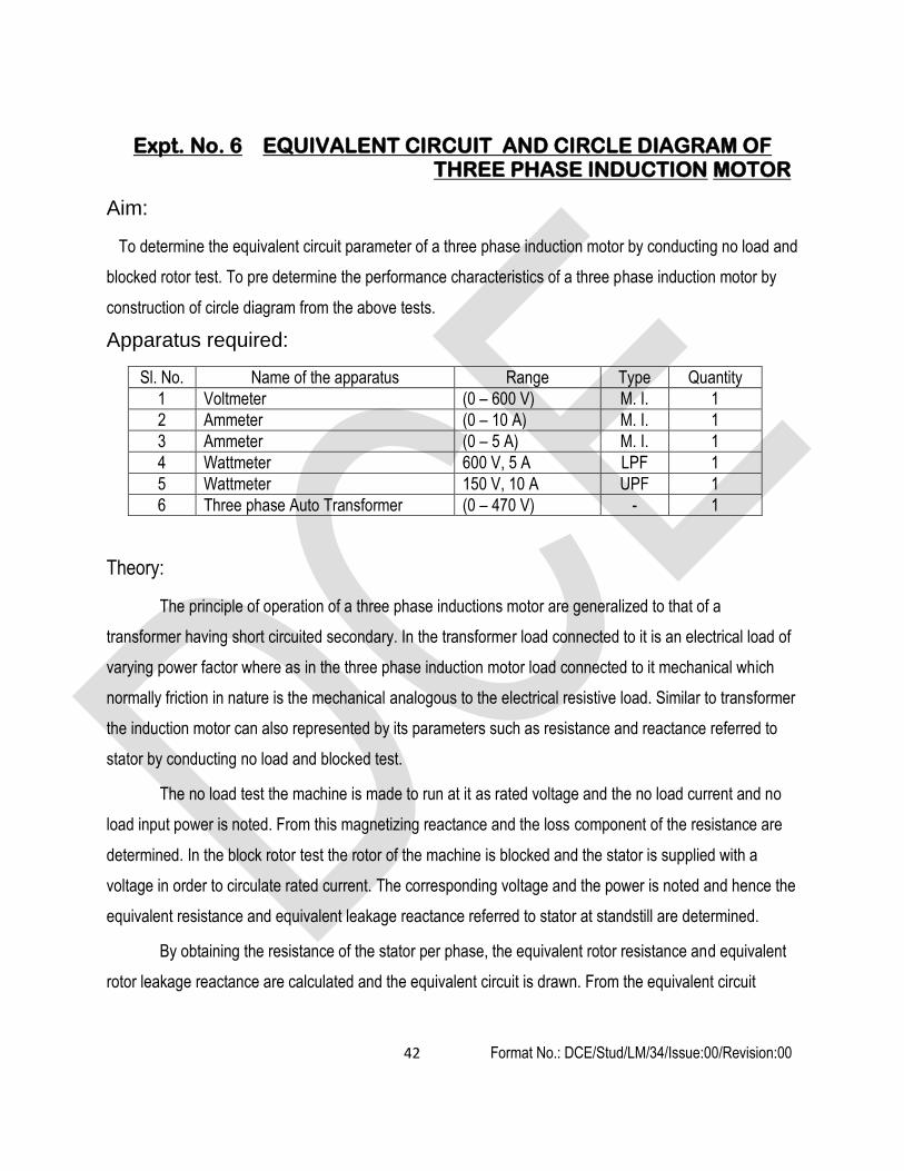
Expt. No. 6 EQUIVALENT CIRCUIT AND CIRCLE DIAGRAM OF THREE PHASE INDUCTION MOTOR
Aim:
To determine the equivalent circuit parameter of a three phase induction motor by conducting no load and
blocked rotor test. To pre determine the performance characteristics of a three phase induction motor by
construction of circle diagram from the above tests.
Apparatus required:
Sl. No. Name of the apparatus Range Type Quantity
1 Voltmeter (0 – 600 V) M. I. 1
2 Ammeter (0 – 10 A) M. I. 1
3 Ammeter (0 – 5 A) M. I. 1
4 Wattmeter 600 V, 5 A LPF 1
5 Wattmeter 150 V, 10 A UPF 1
6 Three phase Auto Transformer (0 – 470 V) - 1
Theory:
The principle of operation of a three phase inductions motor are generalized to that of a
transformer having short circuited secondary. In the transformer load connected to it is an electrical load of
varying power factor where as in the three phase induction motor load connected to it mechanical which
normally friction in nature is the mechanical analogous to the electrical resistive load. Similar to transformer
the induction motor can also represented by its parameters such as resistance and reactance referred to
stator by conducting no load and blocked test.
The no load test the machine is made to run at it as rated voltage and the no load current and no
load input power is noted. From this magnetizing reactance and the loss component of the resistance are
determined. In the block rotor test the rotor of the machine is blocked and the stator is supplied with a
voltage in order to circulate rated current. The corresponding voltage and the power is noted and hence the
equivalent resistance and equivalent leakage reactance referred to stator at standstill are determined.
By obtaining the resistance of the stator per phase, the equivalent rotor resistance and equivalent
rotor leakage reactance are calculated and the equivalent circuit is drawn. From the equivalent circuit

43 Format No.: DCE/Stud/LM/34/Issue:00/Revision:00
parameter and the data from the no load tests, the circle diagram is constructed and its performance is pre
determined.
Precaution:
1. All the switches should be kept open at the time of starting the experiment.
2. The three phase auto transformer should be kept at minimum potential position at the time of
starting the experiment.
Procedure:
No load test:
1. Connections are made as per the circuit diagram.
2. Close the T. P. S. T. switch.
3. Start the motor by varying the three phase auto transformer gradually till the rated voltage of the
motor.
4. At no load all the meter readings should noted down.
5. The three phase auto transformer should be reduced to zero potential position.
6. Open the T. P. S. T. switch.
Blocked rotor test:
1. Connections are made as per the circuit diagram.
2. The load applied on the brake drum and the rotor is not allowed to rotate.
3. Close the T. P. S. T. switch.
4. The three phase auto transformer should be adjusted gradually till the ammeter reads the rated
current of the motor.
5. All the meter readings should be noted down.
6. The three phase auto transformer should be reduced to zero potential position.
7. Open the T. P. S. T. switch.

44 Format No.: DCE/Stud/LM/34/Issue:00/Revision:00

45 Format No.: DCE/Stud/LM/34/Issue:00/Revision:00
Observation:
Open circuit test:
Sl. No. Voltage, VL (V) Current, I0 (A) Power, W0 (W)
Blocked rotor test:
Sl. No. Voltage, VSC (V) Current, ISC (A) Power, WSC (W)
Ra = ___________ Ω
Calculation:
W0 = √3 VL I0 COS ф0
COS ф0 = W0 / ( √3 VL I0)
IW = I0Ph COS ф0
Im = I0Ph SIN ф0
R0 = VS / IW Ω
Xm = VS / Im Ω
WSC = √3 VSC ISC COS ФSC
COS фSC = WSC / (√3 VSC ISC)
RS = WSC / (3 IS2)
ZS = VSC / IS
XS = √ ZS2 - RS
2
RS = rs + rr1
xs = Xrl = xs / 2
RLl = rr
l ((1 - s) / s)
VS – Rated stator voltage per phase
IS – Rated stator current per phase
IOPh – No load current per phase

46 Format No.: DCE/Stud/LM/34/Issue:00/Revision:00
PROCEDURE TO DRAW THE CIRCLE DIAGRAM:
1. Draw the lines by taking the current (I) in X-Axis, Voltage (V) in Y-Axis (V and I are line values).
2. From the no-load test, find out current I0 and draw the OA vector with magnitude of I0 from the origin with
suitable current scale, which lags the voltage (Y-Axis) V by angle φ0.
3. From current Isc, find out the Isn (Short Circuit current corresponding to the normal voltage). Draw the OB
vector with magnitude of Isn from the origin with the same current scale, which lags the voltage (Y-axis) V by
angle φsc.
4. Join the points B and A, and get the output line.
5. Draw the parallel line to X-axis (point E) from point A and parallel line to Y-Axis from point B up to the X-
axis, and let both intersect at point D.
6. Draw the bisector for the output line and extend it to the line AD, and let the point of intersection by C.
7. By keeping the point C as center, draw a semi-circle with radius CA.
8. Let EB be the line of total losses (EB = ED + DB, where ED = constant loss and DB = variable loss)
9. In the line DB, locate the point G to separate the stator and rotor copper losses by using the formula,
or
Where, R1 = Stator resistance per phase and R’2 = Equivalent rotor resistance per phase.
10. To get the torque line, join A and G.
11. To find the load quantities, draw line BK (Full load output power / power scale). Now, draw the line PK
parallel to output line meeting the line at P.
12. Draw the line PT parallel to Y-axis meeting output line at Q, torque line at R, constant line at S and X-axis at
T.
Note:Choose the current line such that the circle diagram will be as large as possible. The larger the circle
diagram more will be accuracy.
Select

47 Format No.: DCE/Stud/LM/34/Issue:00/Revision:00
FORMULAE:
1. Stator resistance in Ohms is assumed as Rs = Ohms.
2. o = Cos -1 (Wo/ 3 Vo Io)
3. sc = Cos-1 (Wsc/ 3 VscIsc)
4. Short Circuit current at normal voltage Isn = (Vo/Vsc) Isc.
5. Stator Cu Loss = 3 Isn2Rs
6. Rotor Cu Loss = Total Cu Loss - 3 Isn2Rs
FROM CIRCLE DIAGRAM:
1. BG/GD = Rotor Cu Loss/Stator Cu loss
2. Efficiency = (PQ/PT) x 100 %
3. Slip = (QR/PR) x 100 %
4. Power factor = PT/OP
Result:
The equivalent circuit is drawn and performance is predetermined by conducting no load and blocked
rotor tests on given three phase induction motor.
Outcome:
By doing this experiment, the circuit parameters of three phase squirrel cage induction motor has been
obtained by No load test and blocked rotor test.
Application:
1. Procedure is being used in the manufacturing industry to predetermine the performance of the machine at its rated load condition. 2. Three phase squirrel cage induction motors are used in the following application
Cooling fans to cool large machines Exhaust fans at chimneys of power plant Printing machines Rolling mills

48 Format No.: DCE/Stud/LM/34/Issue:00/Revision:00
1. Why rated voltage of the stator winding to be applied on load?
2. What are the losses accounted in the no load test?
3. Is it necessary to circulate rated stator current during blocked rotor test?
4. How the mechanical load is represented in equivalent circuit?
5. Under what condition the phasor diagram and equivalent circuit are drawn for a three phase induction motor?
6. How to determine the maximum output for the given induction motor from the circle diagram?
7. How to determine the maximum torque for the given induction motor from the circle diagram?
8. Mention the unit for torque in the circle diagram.
Viva - voce

49 Format No.: DCE/Stud/LM/34/Issue:00/Revision:00
Expt. No. 7 EQUIVALENT CIRCUIT OF SINGLE PHASE INDUCTION MOTOR
Aim:
To draw the equivalent circuit of the given single phase induction motor by conducting no load and
blocked rotor test
Apparatus required:
Sl. No. Name of the apparatus Range Type Quantity
1 Voltmeter (0 – 300 V) M. I. 1
2 voltmeter (0 – 150 V) M. I. 1
3 Ammeter (0 – 10 A) M. I. 1
4 Ammeter (0 – 5 A) M. I. 1
5 Wattmeter 300 V, 5 A LPF 1
6 Wattmeter 150 V, 10 A UPF 1
7 Single phase Auto Transformer (0 – 270 V) - 1
Theory:
The single phase induction motor operates on the principle of doublefield
revolving theory. Normally single phase induction motors are capacitor start in type. In
this type the capacitor is connected in series auxiliary or staring winding and in turn
connected to centrifugal switch. This forms the starting circuit of the single phase
induction motor. This circuit is connected in parallel with main or running winding. The
starting circuit will be isolated from the supply when the motor attains normal speed. At
normal speed or at any actual load condition the running winding alone will be
connected to the supply. Similar to that of three phase induction motor the performance
of the single phase induction motor can be predetermined by obtaining the equivalent
circuit parameters.
In the blocked rotor test the running winding and the starting circuit are
connected in parallel and in turn connected to the supply through a variable voltage
source. When the applied voltage approaches about 50 % the centrifugal switch in
starting circuit will operate and the starting circuit will be isolated because of centrifugal

50 Format No.: DCE/Stud/LM/34/Issue:00/Revision:00
force produced. The power input and current taken by the motor when the rated voltage
is observed.
In the blocked rotor test running winding alone is connected across the
supply through a variable source. The variable voltage source is adjusted till the rated
current is circulated and the corresponding power is noted. Since the starting circuit is
not connected to the supply, the rotor will not rotate.
Circuit diagram:
Precaution:
1. All the switches should be kept open at the time of starting the experiment.
2. The single phase auto transformer should be kept at minimum potential position at the time of
starting the experiment.

51 Format No.: DCE/Stud/LM/34/Issue:00/Revision:00
Procedure:
No load test:
1. Connections are made as per the circuit diagram.
2. Close the D. P. S. T. switch.
3. Start the motor by varying the single phase auto transformer gradually to its rated voltage.
4. All the meter readings should noted down.
5. The single phase auto transformer should be reduced to zero potential position.
6. Open the D. P. S. T. switch.
Blocked rotor test:
1. Connections are made as per the circuit diagram.
2. Close the D. P. S. T. switch.
3. The single phase auto transformer should be adjusted gradually till the ammeter reads the rated
current of the motor.
4. All the meter readings should be noted down.
5. The three phase auto transformer should be reduced to zero potential position.
6. Open the D. P. S. T. switch.
Observation:
No load test:
Sl. No. Voltage, V0 (V) Current, I0 (A) Power, W0 (W)
Blocked Rotor test:
Sl. No. Voltage, VSC (V) Current, ISC (A) Power, WSC (W)

52 Format No.: DCE/Stud/LM/34/Issue:00/Revision:00
Calculation:
W0 = V0 I0 COS ф0
COS ф0 = W0 / (V0 I0)
IW = I0 COS ф0
Im = I0 SIN ф0
R0 = VO / IW Ω
Xm = V0 / Im Ω
R0 = VS / IW Ω
Xm = VS / Im Ω
WSC = VSC ISC COS фSC
RS = WSC / ( IS2)
ZS = VSC / IS
XS = √ ZS2 - RS
2
RS = rs + rr1
xs = Xrl = xs / 2
Result:
Thus the equivalent circuit of single phase induction motor has been drawn using no load and blocked
rotor tests.
Outcome:
By doing this experiment the circuit parameters of single phase induction motor has been obtained by
conduction No-load and blocked rotor tests
Application:
1. Procedure is being used in the manufacturing industry to predetermine the performance of the machine at its rated load condition. 2. Three phase squirrel cage induction motors are used in the following application
Air conditioner and refrigerator

53 Format No.: DCE/Stud/LM/34/Issue:00/Revision:00
Ceiling fans and blowers Machine tool drive and Pump drive
1. What are the losses present in the no load test? 2. In the blocked rotor test the power input to the motor corresponds to copper loss, how?
Viva - voce

54 Format No.: DCE/Stud/LM/34/Issue:00/Revision:00
Expt. No. 8 DETERMINATION OF NEGATIVE SEQUENCE AND ZERO SEQUENCE REACTANCE OF THREE PHASE
ALTERNATOR
Aim:
To obtain the negative sequence and zero sequence reactance of a given three phase alternator
Apparatus required:
Sl. No. Name of the apparatus Range Type Quantity
1 Voltmeter (0 – 300 V) M. I. 1
2 Voltmeter (0 – 150 V) M. I. 1
3 Ammeter (0 – 20 A) M. I. 1
4 Ammeter (0 – 10 A) M. I. 1
5 Ammeter (0 – 2 A) M. I. 1
6 Wattmeter 300 V, 10 A UPF 1
7 Rheostat 220 Ω, 2 A - 1
8 Single phase Auto Transformer (0 – 270 V) - 1
9 Tachometer (0 – 10000 rpm) Digital 1
Theory:
When a synchronous generator is carrying an unbalanced load its operation may be analyzed by
symmetrical components. In a synchronous machine the sequence current produce an armature reaction
which is stationary with respect to reactance and is stationary with respect to field poles. The component
currents therefore encounter exactly same as that by a balanced load as discussed. The negative
sequence is produced and armature reaction which rotates around armature at synchronous speed in
direction to that of field poles and therefore rotates part the field poles at synchronous speed. Inducing
current in the field damper winding and rotor iron. The impendence encountered by the negative sequence
is called the – ve sequence impedance of the generator. The zero sequence current produce flux in each
phase but their combined armature reaction at the air gap is zero. The impedance encountered by their
currents is therefore different from that encountered by + ve and –ve sequence components and is called
zero sequence impedance of generator. The –ve sequence impedance may be found by applying
balanced –ve sequence voltage to the armature terminals. While the machine is drive by the prime mover

55 Format No.: DCE/Stud/LM/34/Issue:00/Revision:00
at its rated synchronous speed with the field winding short circuited. The ratio of v/ph and Ia/ph gives –ve
sequence Z/ph. The reading of the wattmeter gives I2 R losses. This loss /ph divided by Iph required gives
the –ve sequence R/ph from the impedance and reactance/ph. –ve sequence can be calculated. Another
method of measuring –ve sequence reactance is found to be connect the arm terminals. The machine is
driven at synchronous speed and field current adjusted until rated current flows in the phases shorted
through armature and current coil of wattmeter respectively.
The sequence impedance may be determined by the connecting the armature windings of the three phase
in series and then connecting them to the single phase source of power. If the machine is driven at
synchronous speed with field winding shorted, then ZO=V/3I practically the same results will be obtained
with rotor stationary
Circuit diagram:
Precaution:

56 Format No.: DCE/Stud/LM/34/Issue:00/Revision:00
1. All the switches should be kept open at the time of starting the experiment.
2. The D. C. motor field rheostat should be kept at minimum resistance position at the time of starting
the experiment.
3. The generator field potential divider should be kept at minimum potential position.
Procedure:
1. Connections are made as per the circuit diagram.
2. The motor should be started with the help of three point starter.
3. The motor speed should be made equivalent to alternator synchronous speed with the help of field
rheostat of the motor.
4. The D. P. S. T. switch on the alternator field side should be closed.
5. The alternator field potential divider must be varied in steps.
6. At each step, all the meter readings should be noted down.
7. The above procedure should be repeated till the ammeter reads the rated alternator current.
Observation:
Sl. No.
Voltage VRY (V)
Current ISC (A)
Power (W)
Negative sequence
impedance (Z2)
Negative sequence reactance
(X2)
Average (X2)
1
2
3
4
Calculation:
Z2 = VRY / (3 ISC)
X2 = Z2 (W2 / (VRY × ISC ))
Zero sequence parameters:
Precaution:

57 Format No.: DCE/Stud/LM/34/Issue:00/Revision:00
1. All the switches must be kept open at the time of starting the experiment.
2. The auto transformer should be kept at minimum potential position.
Procedure:
1. Connections are made as per the circuit diagram.
2. The auto transformer should be varied in steps.
3. At each step the meter readings should be noted down.
4. The above procedure should be repeated till the ammeter reads rated current of the alternator.
Observation:
Sl. No. Observation Calculation
Voltage (V) Current (A) X0 = (3 V) / I Average (X0)
1
2
3
Result:
Thus the negative sequence reactance and zero sequence reactance have been determined.
Outcome:
By doing this experiment, the negative sequence reactance and zero sequence reactance for the given
three phase alternator is understood.
Application:
The procedure is used to make analysis for the further expansion of existing power system
network.

58 Format No.: DCE/Stud/LM/34/Issue:00/Revision:00
1. What is meant by sequence voltage?
2. What are symmetrical components?
3. What is the need for symmetrical components?
4. Which sequence current flows through the ground and why?
5. How does the neutral grounding affect zero sequence impedance?
6. What are the types of sequence components?
7. What are the experiments to be conducted to obtain sequence components on an alternator?
Viva - voce

59 Format No.: DCE/Stud/LM/34/Issue:00/Revision:00
Expt. No. 9 SLIP TEST ON THREE PHASE ALTERNATOR
Aim:
To obtain the direct axis and quadrature axis components for the given three phase alternator
Apparatus required:
Sl. No. Name of the apparatus Range Type Quantity
1 Voltmeter (0 – 600 V) M. I. 1
2 Voltmeter (0 – 300 V) M. I. 1
3 Ammeter (0 – 5 A) M. I. 1
4 Rheostat 220 Ω, 2 A - 1
5 Three phase Auto Transformer (0 – 470 V) - 1
Theory:
The method used to determine Xq and Xd, the direct and quadrature axis reactance is called slip test. In
an alternator we apply excitation to the field winding and voltage gets induced in the armature. But in the
slip test, a three phase supply is applied to the armature, having voltage must less than the rated voltage
while the field winding circuit is kept open. The alternator is run at a speed close to synchronous but little
less than synchronous value. The three phase currents drawn by the armature from a three phase supply
produce a rotating flux. Thus the armature m.m.f. wave is rotating at synchronous speed Note that the
armature is stationary, but the flux and hence m.m.f. wave produced by three phase armature currents is
rotating. This is similar to the rotating magnetic field existing in an induction motor. The rotor is made to
rotate at a speed little less than the synchronous speed. Thus armature m.m.f. having synchronous speed,
moves slowly past the filed poles at a slip speed (ns -n) where n is actual speed of rotor. This causes an
e.m.f. to be induced in the field circuit. When the stator m.m.f. is aligned with the d-axis of field poles then
flux Φd per poles is set up and the effective reactance offered by the alternator is Xd. When the stator
m.m.f. is aligned with the q-axis of field poles then flux Φq per pole is set up and the effective reactance
offered by the alternator is Xq. As the air gap is non uniform, the reactance offered also varies and hence
current drawn the armature also varies cyclically at twice the slip frequency. The r.m.s. current is minimum

60 Format No.: DCE/Stud/LM/34/Issue:00/Revision:00
when machine reactance is Xd and it is maximum when machine reactance is Xq. As the reactance offered
varies due to non uniform air gap, the voltage drops also varies cyclically. Hence the impedance of the
alternator also varies cyclically. The terminal voltage also varies cyclically. The voltage at terminals is
maximum when current and various drops are minimum while voltage at terminals is minimum when
current and various drops are maximum. The waveforms of voltage induced in rotor, terminal voltage and
current drawn by armature. It can observed that rotor field is aligned with the armature m.m.f., its flux
linkage are maximum, but the rate of change of flux is zero. Hence voltage induced in field goes through
zero at this instant. This is the position where alternator offers reactance Xd. While when rate of change of
flux associated with rotor is maximum, voltage induced in field goes through its maximum. This is the
position where alternator offers reactance Xq.
Circuit diagram:
Precaution:
1. All the switches should be kept open at the time of starting the experiment.
2. There should be no load at the time of starting the experiment.

61 Format No.: DCE/Stud/LM/34/Issue:00/Revision:00
3. The motor field rheostat should be kept at minimum resistance position.
Procedure:
1. Connections are made as per the circuit diagram.
2. The D. P. S. T. switch should be closed.
3. The motor should be started with the help of three point starter.
4. The motor speed should be made equivalent to alternator synchronous speed with the help of field
rheostat of the motor.
5. The auto transformer should be varied to get maximum variations in the meter.
6. All the readings should be noted down.
Observation:
Sl. No. Maximum voltage (V)
Minimum voltage (V)
Maximum current (A)
Minimum current (A)
Calculation:
Xd = (Maximum Voltage / √3 ) / Minimum current
Xq = (Minimum voltage / √ 3) / Maximum current
d – direct axis component
q – quadrature axis component
Result:
The direct axis and quadrature axis component of the three phase alternator have been calculated.
Outcome:
By doing this experiment, the Xd and Xq components of the given three phase alternator by conducting
slip test has been understood.

62 Format No.: DCE/Stud/LM/34/Issue:00/Revision:00
Application:
Procedure is being used in the manufacturing industry to predetermine the regulation of the machine.
1. Why OCC looks like B-H curve?
2. Why SCC is a straight line?
3. What is armature reaction effect?
4. What are the causes of voltage drop?
5. When is the regulation negative and why?
6. Can we find regulation of a salient pole machine by this test? Justify your answer.
7. Justify that the reactance obtained by O.C. & S.C test is Xd and not Xq.
8. Defined Xd and Xq.
9. What are the normal values of Xq/Xd for the two types of syn. Machines.
10. How will you recognize whether a given syn. machine is cylindrical rotor type or salient pole type.
11. Why this test is called slip test.
12. Why it is necessary to maintain the slip.
13. What are the main assumptions during this test.
14. Why it is necessary to keep the field open while taking the reading during slip test.
Viva - voce
63 Format No.: DCE/Stud/LM/34/Issue:00/Revision:00
Expt. No. 10 SEPARATION OF NO LOAD LOSSES IN A THREE PHASE
INDUCTION MOTOR AIM:
To separate mechanical and iron losses of a three phase induction motor by conducting no load test at its rated
voltage.
APPARATUS REQUIRED:
S.No. Apparatus Range Type Quantity
1 Ammeter (0-10)A MI 1
2 Voltmeter (0-600)V MI 1
3 Wattmeter 600V,10A UPF 2
4 Autotransformer 3 - 1
THEORY:
The induction motor runs on no load at its rated voltage takes input power which is to overcome the loses
namely stator copper loss, iron loss and mechanical loss. To separate the mechanical and iron loss in the induction
motor, the methods available are changing the frequency keeping the flux constant and changing the flux with
frequency constant. Normally, variable flux is possible by varying the applied voltage applied to the stator. But for
changing the frequency it requires a frequency conversion device. Initially the stator is supplied to its rated voltage
which makes the magnetic circuit of the machine magnetized to its maximum value of flux. As the voltage decreased
the value of the flux decreased in the magnetic circuit and it takes sufficient time to stabilize. Hence, a time interval is
given to note down the input power. The stator copper loss is subtracted from no load input for a different value of
voltage. A graph is drawn between stator voltage and iron and mechanical losses. In this method iron and
mechanical losses are separated for a given stator voltage.
PRECAUTIONS:
1. Three phase Autotransformer should be in the minimum potential position at the time of starting and
stopping of the motor.
PROCEDURE:
1. Connections are made as per the circuit diagram.
2. By adjusting the auto transformer the rated voltage of the induction motor is applied

64 Format No.: DCE/Stud/LM/34/Issue:00/Revision:00
3. The corresponding Ammeter and wattmeter readings are noted.
4. In the similar way the voltage applied to the motor is decreased, allow the motor to run at this voltage then
corresponding voltmeter, ammeter and wattmeter readings are noted.
5. Likewise gradually the voltage applied to the stator reduced to least voltage and corresponding meter
readings are noted.
6. The stator resistance per phase is measured.
7. From the no load power the stator copper losses are subtracted for all the stator copper loss calculated.
8. The resultant power available is sum of mechanical losses and iron losses
9. A graph is drawn between voltage applied and the sum of mechanical loss and iron loss. The curve is
extrapolated with the same slope and it will cut y-axis at some point.
10. The point where y-axis is cut corresponds to mechanical loss and hence iron loss can be calculated.
CALCULATION
1. The no load power measured is equal to no load stator copper loss, iron loss and mechanical
losses.
2. Calculate the no load stator copper loss for all the readings taken.
3. Subtract no load stator copper from the no load power input which is equal to iron and mechanical
losses.
4. Take suitable scale for voltage in x-axis and iron loss and mechanical loss on y-axis and draw the
curve.
5. Extend the curve and it cuts y-axis at A. OA is equal to mechanical loss of the machine.
6. At the rated voltage, draw a vertical line it cuts curve drawn at point B. From the point B draw a
horizontal line which cuts y-axis at point C. the OC represents iron loss and mechanical loss at its rated
voltage. Subtract OA from OC which is equal to iron loss at its rated voltage.

65 Format No.: DCE/Stud/LM/34/Issue:00/Revision:00

66 Format No.: DCE/Stud/LM/34/Issue:00/Revision:00
TABULAR COLUMS
NO LOAD TEST: Multiplying Factor MF = ______
S.No. voltage (Volts)
Current (Amps)
Watt meter Reading Total power Watts
I2R Watts
Wi + Wm Watts W1(Watts) W2(Watts)
RESULT:
The iron loss and mechanical losses of the given three phase induction motor are separated at its operating
voltage.
Application:
Procedure is being used in the manufacturing industry to determine the economical operation of the machine at its rated load condition.
Viva-voce questions
1. Why the stator copper loss is subtracted from no load power input?
2. Is the iron and mechanical losses are constant?

67 Format No.: DCE/Stud/LM/34/Issue:00/Revision:00
Expt. No. 11 REGULATION OF THREE PHASE SALIENT POLE
ALTERNATOR BY SLIP TEST AIM:
To predetermine the full load regulation of the given three phase salient pole alternator by
conducting slip test.
APPARATUS REQUIRED:
S.No. Apparatus Range Type Quantity
1 Ammeter (0-10)A
(0-10)A
MI
MC
1
1
2 Voltmeter (0-150)V
(0-300)V
MI
MC
1
1
3 Rheostats 300 ,0.8 A Wire Wound 1
4 Autotransformer 3 - 1
5 Tachometer (0-1500)rpm Digital 1
6 Connecting Wires 2.5sq.mm. Copper Few
PRECAUTIONS:
1. The field rheostat of motor should be in minimum resistance position at the time of starting and
stopping the machine.
2. The autotransformer should be in minimum Potential position at the time of starting and
stopping the machine.
PROCEDURE:
1. Connections are made as per the circuit diagram. The dc motor is started with help of a starter
2. The motor is made to run at a speed less than that of the synchronous speed of the salient pole
alternator by adjusting the motor filed rheostat.

68 Format No.: DCE/Stud/LM/34/Issue:00/Revision:00
125 x
---------------- = A
100
CIRCUIT DIAGRAM: REGULATION OF THREE PHASE SALIENT POLE ALTERNATORBY SLIP TEST
T
P
S
T
S
W
I
T
C
H
A2
2
W
I
T
C
H
_
+
SUPPLY
V
~
R
Y B
F1 A1
1
L F A
THREE POINT STARTER
F2
A
M V
R
Y
B e
A
A
3 phase Auto transformer

69 Format No.: DCE/Stud/LM/34/Issue:00/Revision:00
3. After closing the TPST switch, on the ac side is closed and the three phase auto-transformer
output is adjusted smoothly ensuring the stator current should not exceed the rated value.
4. While varying the auto transformer at one instant, the ammeter and the voltmeter will oscillate
with a min. and max. values
5. By adjusting the autotransformer tries to get maximum oscillation in the ammeter and the
voltmeter connected in the alternator circuit.
6. The corresponding maximum and minimum current and voltages are noted.
7. The supply to the alternator is removed and the dc motor is stopped.
THEORY
The pre determination of full load regulation of a salient pole alternator is normally done by
conducting slip test. In this alternator the air gap length is not same over the outer periphery of the
rotor. It is mainly due to the projection of poles and pole shoes in the rotor. The pole shoes will be
curved in shape at air gap. In order to predict the regulation of the alternator, the two parameters
namely direct axis synchronous reactance and quadrature axis synchronous reactance are to be
obtained from the slip test.
The slip test is conducted, by applying a variable three phase voltage to the stator and the field
winding in the rotor is kept open. The three phase voltage applied to the stator will produce a revolving
magnetic field at its synchronous speed. The rotor made to run at the speed less than the synchronous
speed the axis of the stator pole and rotor pole coincides at a particular instant. At this instant the MMF
required to force the flux will be minimum because the air gap length is minimum. Since the MMF is less
the current required is less and flux linkage is maximum that is the applied voltage is maximum. This will
give the value of the direct axis synchronous reactance.
In the similar way the stator pole axis coincides with the rotor inter polar axis (90 degrees
electrical from the rotor pole axis), at this instant the MMF required to force the flux will be maximum
because air gap length is maximum. Since the MMF is high the current required is more and flux linkage
is minimum that is the applied voltage is minimum. This will give the value of the quadrature axis
synchronous reactance.

70 Format No.: DCE/Stud/LM/34/Issue:00/Revision:00
TABULAR COLUMN:
S.No. Vmax
(Volts)
Vmin
(Volts)
Imin
(Amps)
Imax
(Amps)
Xd
(Ohms)
Xq
(Ohms)

71 Format No.: DCE/Stud/LM/34/Issue:00/Revision:00
FORMULAE:
.Xd= max input voltage per phase / minimum stator current per phase Ohms / phase
Xq=min input voltage per phase / maximum stator current per phase Ohms / phase
MODEL CALCULATION:
RESULT:
72 Format No.: DCE/Stud/LM/34/Issue:00/Revision:00
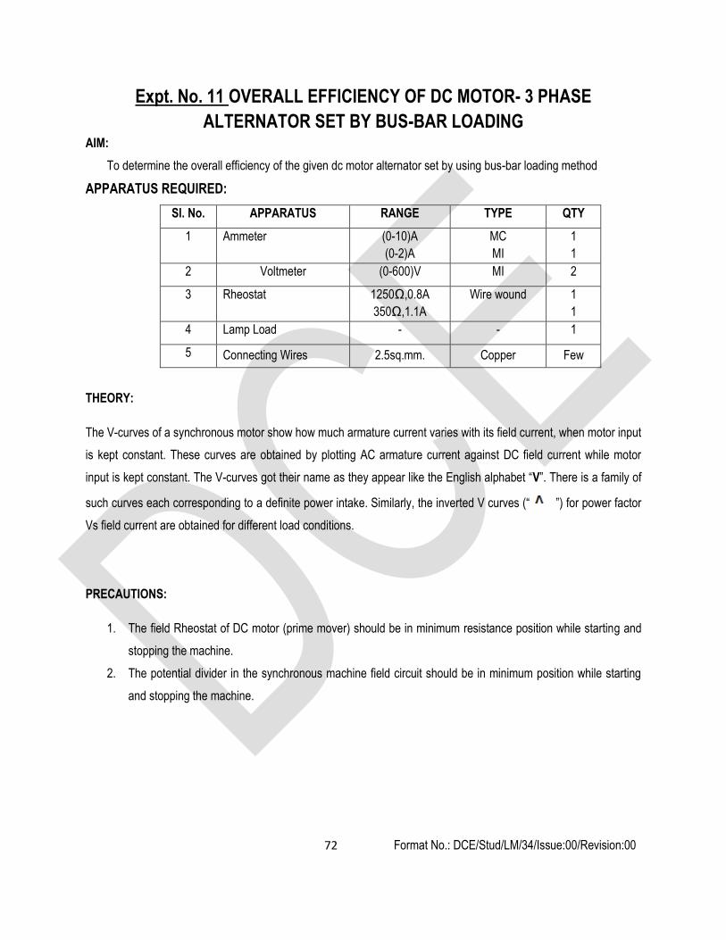
Expt. No. 11 OVERALL EFFICIENCY OF DC MOTOR- 3 PHASE
ALTERNATOR SET BY BUS-BAR LOADING AIM:
To determine the overall efficiency of the given dc motor alternator set by using bus-bar loading method
APPARATUS REQUIRED:
Sl. No. APPARATUS RANGE TYPE QTY
1 Ammeter (0-10)A
(0-2)A
MC
MI
1
1
2 Voltmeter (0-600)V MI 2
3 Rheostat 1250Ω,0.8A
350Ω,1.1A
Wire wound 1
1
4 Lamp Load - - 1
5 Connecting Wires 2.5sq.mm. Copper Few
THEORY:
The V-curves of a synchronous motor show how much armature current varies with its field current, when motor input
is kept constant. These curves are obtained by plotting AC armature current against DC field current while motor
input is kept constant. The V-curves got their name as they appear like the English alphabet “V”. There is a family of
such curves each corresponding to a definite power intake. Similarly, the inverted V curves (“ ”) for power factor
Vs field current are obtained for different load conditions.
PRECAUTIONS:
1. The field Rheostat of DC motor (prime mover) should be in minimum resistance position while starting and
stopping the machine.
2. The potential divider in the synchronous machine field circuit should be in minimum position while starting
and stopping the machine.

73 Format No.: DCE/Stud/LM/34/Issue:00/Revision:00
MI
A2
2
MI
F2
W
I
T
C
H
+
_
V
F2
+ A
F1
A
W
I
T
C
H
+
L1
L2
L3
CIRCUIT DIAGRAM: V CURVES AND INVERTED V CURVES OF SYNCHRONOUS MOTOR
_
SUPPLY
R
Y B
F1 A1
1
L F A
M
-
SUPPLY
Y
B
Rated Current :
Rated Power :
V

74 Format No.:DCE/Stud/LM/34/Issue:00/Revision:00
PROCEDURE:
1. The connections are made as per the circuit diagram.
2. The switches DPST is and the DC motor is started with the help of a starter.
3. The filed rheostat of the motor (prime mover) is adjusted such that the alternator runs at its
Synchronous speed.
4. The TPST1 switch is closed and the AC supply voltage (VL) is noted down. And TPST 1
is opened
5. The synchronizing switchTPST2 switch is closed and the potential divider of the
alternator is adjusted to induce a voltage equal to that of the supply voltage ( When
TPST1 was closed)
6. The synchronizing switch TPST 2 is opened and the TPST 1 switch is closed.
7. The synchronizing lamps (L1, L2, and L3) will start flickering. When all the bulbs are
flickering simultaneously, means the phase sequence condition is satisfied.
8. The field rheostat of the shunt motor (prime mover) is adjusted such that the frequency of
the alternator is varied thereby the period of brightness to darkness of the bulbs are
extended. When the all the bulbs are dark, then the frequency of the alternator and the
supply are equal.
9. The synchronizing switch TPST 2 is closed when all lamps undergo complete darkness.
10. Adjust the filed rheostat of the dc motor (by increasing the mechanical input to the
alternator or increasing the speed of the dc motor) for various values of dc motor current,
voltage, the corresponding voltage current and the wattmeter readings are noted
11. The field rheostat of the dc motor is varied till the alternator or the dc motor rated current
is reached
TABULAR COLUMN:
S.No Vdc
Volts
Idc
Amps
Input
power
Watts
Wattmeter
W
Watts
Total power
3xW
Watts
Efficiency
3xW
/VdcxIdc

75 Format No.:DCE/Stud/LM/34/Issue:00/Revision:00
MODEL GRAPH:
(1) Armature current Vs Excitation current. (2) Power factor Vs Excitation current
RESULT:
The overall efficiency of the given dc motor alternator set is determined by bus-bar loading method.
Application:
The procedure is employed in the power plants to make all the alternators to operate parallel.
VIVA QUESTIONS
1. In which motor we perform this experiment? 2. What is the speed nature of 3-phase synchronous motor? 3. What is the purpose of this experiment? 4. What is the characteristic of v curve? 5. What is the characteristic of Λ curve? 6. What are the different range of loads used in this experiment? 7. How will you apply load in this experiment? 8. Application of synchronous motor? 9. What is the armature current nature when load is applied in V curve? 10. What is the field current nature when load is applied in Λ curve?