Embed Size (px)
Citation preview

LABORATORY FACILITIES FOR RESEARCH AND DEVELOPMENT OF WATER SYSTEMS CONTROL
AUTOMATION
Hydraulics Branch Division of Genera/Research
Engineering and Research Center Bureau of Reclamation
April 1977 GR-5-77

MS-230 (1 -76) Bureau of R e c l a m a t i o n
I R E P O R T N(}. ~ :~ " : ' i i ' ~ { ~ A ' ¢ ~ I ~ . ~ N ' ~ ' ~ L . . . . . . ~, _.N . . . . .
'IL/JLIL ¢,1' I | I
4. T I T L E AND S U B T I T L E
Laboratory Facilities for Research and Development of Water Systems Control Automation
7. A U T H O R ( S )
J. C. Schuster and P. F. Enger
9. P E R F O R M I N G O R G A N I Z A T I O N NAME AND ADDRESS
Bureau of Reclamation Engineering and Research Center Denver, Colorado 80225
12. SPONSORING A G E N C Y NAME AND ADDRESS
Same
TECHNICAL REPORT STANDARD T I T L E PAGE 3. R E C I P I E N T ' S C A T A L O G NO. t'
5. R E P O R T D A T E
April 1977 6. P E R F O R M I N G O R G A N I Z A T I O N CODE
8. P E R F O R M I N G O R G A N I Z A T I O N R E P O R T NO.
GR-5.77 10. WORK U N I T NO.
11. C O N T R A C T OR G R A N T NO.
13. T Y P E OF R E P O R T AND P E R I O D C O V E R E D
14. SPONSORING A G E N C Y CODE
15. S U P P L E M E N T A R Y NOTES
16. A B S T R A C T
Facilities have been provided in the Hydraulics Branch Laboratory, Division of General Research, Engineering and Research Center to investigate methods and means of automating and remotely contr'olling irrigation systems for the Bureau of Reclamation. This report describes these laboratory and field facilities for studying, developing, and demonstrating control methods for automatic flow regulation.
17, KEY WORDS AND DOCUMENT ANALYSIS a. D E S C R I P T O R S - - / a u t o m a t i o n / h y d r a u l i c m o d e l s / c a n a l s / d a t a a c q u i s i t i o n /
e lectronics / radial gates / control e q u i p m e n t / ins trumentat ion / computers
b. IDENTIFIERS-°
c COSATI Field/Group 14B COWRR: 1402 18. D I S T R I B U T I O N S T A T E M E N T
Avai lab le from the Nat ional Technical Information Service, Operations Division, Springfield, Virginia 22151.
19, SECURITY CLASS 121. NO. OF PAGES (THIS REPORT) I 2 4
U-NC~AfS IF I E D 20. SECURITY CLASS 22. PRICE
(THIS PAGE)
UNCLASSIFIED
I I I I I !
I I I I I I I I I I I 1
m SI METRIC
GR-5-77
LABORATORY FACILITIES FOR
RESEARCH AND DEVELOPMENT
OF WATER SYSTEMS CONTROL
AUTOMATION
by J. C. Schuster
P. F. Enger
Hydraulics Branch Division of General Research
Engineering and Research Center Denver, Colorado
April 1977
I I I
UNITED STATES DEPARTMENT OF THE INTERIOR BUREAU OF RECLAMATION
I I I I I I i I I I i I i I
I l I
C O N T E N T S
I n t r o d u c t i o n .........................................
L a b o r a t o r y facil i t ies ....................................
E lec tzon ics shop .....................................
Cana l mode l ........................................
Opeza t ing charac te r i s t i c s ...............................
D a t a acquis i t ion . . . . . . . . . . . . . . . . . "', . . . . . . . . . . . . . . . . . .
Genera l pu rpose m e a s u r e m e n t analysis
and con t ro l c o m p u t e r sys t em ...............................
H y d r a u l i c t r ans ien t c o m p u t e r mode l s . . . . . . . . . . . . . . . . . . . . . . . .
E n v i r o n m e n t a l t e s t facili t ies ...............................
Rad ia l ga te mode l ......................................
F ie ld d e v e l o p m e n t ( l abo ra to ry extens ion) . . . . . . . . . . . . . . . . . . . . . .
Page
3
4
4
6
6
7
7
Figure
1
2
3
4
5
6
7
8
9
10
F I G U R E S
Plan of hydraul ic labora tory . . . . . . . . . . . . . . . . . . . . . . . . . .
Canal model . . . . . . . . . . . . . . . . . . . . . . . . . . . . . . . . . . . .
General layout of canal model . . . . . . . . . . . . . . . . . . . . . . . .
Suppo r t f raming details o f canal mode l . . . . . . . . . . . . . . . . . .
Me ta lwork details of canal model . . . . . . . . . . . . . . . . . . . . . .
Cont ro l panels, f lume, and side spill weirs
of canal model ..................................
General layout of radial gate for canal model . . . . . . . . . . . . .
Me ta lwork details of radial gate . . . . . . . . . . . . . . . . . . . . . . .
M e a s u r e m e n t analysis and cont ro l
c o m p u t e r sys tem .................................
Radial gate model ................................
ii
Page
9
10
11
13
15
17
19
21
23
24
I I I I I I I I I I I I I I I I I I
INTRODUCTION
This report was prepared in accordance with the following: (1) U.S.-U.S.S.R.
Agreement on Cooperation in the Field of Science and Technology signed May 24,
1972, (2) the record of the first meeting of the U.S.-U.S.S.R. Joint Working Group
on Scientific and Technical Cooperation in the Field of Water Resources signed
September 30, 1972, and (3) in accordance with the program developed by the
U.S.-U.S.S.R. coordinators in Frunze on September 24, 1974, on Project I I I 2,
"Methods and Means of Automation and Remote Control in Irrigation Systems."
Item 3 of the agreement calls for an exchange of information on equipment and
laboratory apparatus used to develop autom~ed controls for water systems. This report
describes certain laboratory and field facilities used by the U.S. Bureau of Reclamation
to study and demonstrate the various control systems available for automatic flow
regulation.
LABORATORY FACILITIES
Electronics Shop
Automation and control facilities in use are located in the Division of General Research,
Hydraulics Branch laboratory at Denver, Colo., see figure 1. A small electronics shop,
run by one technician, is located in a room adjacent to the hydraulics laboratory, see
figure 1 (center right). This shop has been equipped with standard electronics test
equipment such as analog and digital voltmeters; muhimeters measuring voltage,
cur rent , and resistance; oscilloscopes, and spare parts . The shop also has a
microprocessor development system including microprocessor, two ASCII (American
Standard Code for Information Interchange) keyboard and printer terminals, punched
tape, and magnetic tape facilities, all maintained in the shop. An electronics engineer
supervises the development of electronic components, hardware, and software required
for control elements. The shop is in daily use on work associated with the research and

development of water conveyance control equipment for which there is no known
commercial source of supply.
Canal Model
A canal model was constructed in the Hydraulics Branch laboratory to be used for
developing control schemes and equipment, see figure 1 (upper right dashed rectangle).
The model has a rectangular flume approximately 335 m (1100 ft) long and is divided
into three flow sections of unequal length by four radial gate structures, see figure 2.
Bends of 180 o direct the flow from channel to channel at each end of the model. The 0
four channels upstream from gate 2 of the model have been in operat ion for about
3 years. Recently, eight channels and two gates (3 and 4) were added to increase the
versatility of the model. The model, as shown on figures 2 and 6, was constructed from
the detailed drawings shown on figures 3, 4, and 5. The radial gates were constructed
from the drawings shown on figures 7 and 8.
A 3-m (10-ft) crest length spill weir was constructed immediately upstream from each
check gate to waste excess water from the channel upstream from the gate to the next
downstream section. The weir upstream from the first radial gate bypasses the excess
water to the main channel of the laboratory water supply. All water, up to the model
capacity of 0.03 m3/s (1 ft3/s), is pumped from the main channel into the model by
a vert ical turbine pump. The inflow to the model is measured by a l abora tory
constructed Venturi-orifice meter. Orifices ranging in size from 35 to 140 mm (1-3/8
to 5-1/2 in) can be placed in the Venturi throat. The pump is operated at constant
discharge during a study and excess water in the forebay of radial gate 1 is bypassed
to the main channel. If water becomes excessive in a channel, the side spill weir
discharges to the next downstream section. The last weir and radial gate 4 wastes to
the main channel. All of the side spill weirs were designed to discharge 0.03 m3/s for
a water surface rise of approximately 30 mm (0.1 ft) in the model water surface.
2
I I I I I I I I "i I I I I I I I I
I

I I I I i I I I i i I I I
I I I I I
A fully con t rac ted 254-mm (10-in) crest length rec tangular weir was instal led
downstream from each of the radial gates to provide appropriate submergence on the
gate and to measure the discharge. To achieve fully contracted flow, a 203-mm (8-in)
drop was provided in the flume invert downstream from each weir. Each of the side
spill weirs, rectangular weirs, and radial gates are rated with respect to the discharges
through the Venturi-orifice meter.
Operating characteristics .-The three flow sections of the model canal were designed
to have different transitory wave travel times by constructing the sections of different
lengths. Full sized canals have wave travel times of an order of magnitude larger than
the model but control principles can be readily evaluated with the model wave travel
time.
Reflections of waves between the gate structures cannot be studied in this model
because of the rectangular weirs downstream from each gate. Thus, the laboratory
canal does not simulate the irrigation canal with respect to a transitory wave reflecting
between gate structures.
Each of the gates can be operated from a gate controller on the operating platform.
The control panels (in front of each of the two people in the foreground of figure 2)
contain switches and relays for opening and closing the gates. Each panel also contains
voltage terminals from test points in the system. A potentiometer attached to the gate
hoist shaft has a reference voltage terminal on the panel used for indicating the gate
opening and for input to the control equipment under study.
Water levels in the canal are sensed in the model by inductive- or resistive-type
t ransducers connec ted by plast ic tubes to p iezometr ic orifices ups t ream and
downstream of the radial gates. The voltage output of the transducers and signal
conditioning circuits becomes the input to the controller under test.

Water levels are also measured in stilling wells large enough to contain 305-mm (12-in)
diameter floats. The water level change is transmitted through a float, beaded cable,
pulley, and gear reducer to a potentiometer. The stilling well water level may also be
sensed by a pressure transducer connected to the well.
Data acquisition .-Analog and digital instruments are used to acquire data for research
and development of controllers. Analog signals from test points are recorded on
direct-writing recorders. The frequency of control changes usually can be measured
on precision recording voltmeters having relatively slow response. Recorders having
a response up to 100 Hz may be used to advantage for signal conditioning and for
recording the data in laboratory studies. Analog to digital (A/D) conversion of voltages
from test points is necessary for adaptation of minicomputer and microprocessor
applications. Laboratory experiments are normally designed to employ computers in
the research and development of controllers or methods.
GENERAL PURPOSE MEASUREMENT ANALYSIS AND CONTROL
COMPUTER SYSTEM
Located within the Division of General Research is a general purpose Measurement
Analysis and Control Computer System. This system is a real-time data acquisition,
data reduction, and control system; and is maintained and operated by the Division
Instrumentation Group. Although used for general-type measurement, analysis, and
control work in all areas of the division, the system has also been used for control of
the laboratory canal model. The system is controlled by seven minicomputers. A
real-time executive program operates the system and offers many featues such as online
edi t ing, mu l t i p rog ramming , F O R T R A N , system p ro tec t ion , i n p u t - o u t p u t
management, file management, and general coordination of the complete system.
The seven minicomputers are wired together as shown in figure 9a. The main, or central
computer, which drives several peripheral devices has 96 thousand words of 16 bit
4
I I I I I I I I I I I I I I I I I I
I I I I I I I I I I I I I I I I I I
memory, figure 9b. Each branch computer is capable of using the peripheral devices
in the central area of the main computer. These devices, used by all branches of the
Division of General Research, include a card reader (for punched or marked-sense
cards), a line printer, a high-speed paper tape punch, a high-speed paper tape reader,
an X-Y plotter, an interface to the telephone lines, two magnetic disks, three 13-mm
(1/2-in) nine-channel magnetic tape drives, a graphical A /D input system, and various
terminal displays. A keypunch, extra tapes, and other equipment are also maintained.
Branch or remote computers which communicate with the central computer are shown
in figure 9c. The branch computers have 24 thousand words of 16 bit memory, and
may all be used simultaneously from their location in the various branches. The branch
computers are mobile and can be moved from area to area. Output from the branch
computers can be sent to central computer peripheral devices, to the teleprinter at
the branch computer, or to test equipment in the form of real-time control. Input can
be through central computer devices, the teleprinter at the remote, a high.speed paper
tape reader at the remote, or through test equipment such as transducers. Signals from
test equipment can be analog voltages or digital lines. There are many possibilities for
input from test signals and for control output. In general, at each branch computer,
many low-level and high-level sensors (such as strain gages or transducers) and many
output controls (such as relays ) can be connected.
The system is modular and may be expanded or updated at the central system or at
any branch computer. As the branch computers are all similar, the various parts may
be traded between branches. Thus, for example, if one branch desires more input and
another branch is not using their input boards, the additional input may be obtained
on loan to increase the capacity of any one system.
General purpose measurement analysis and control systems such as this one have been
used frequently in the Division of General Research. An example of a short study
conducted with a smaller but similar system was published in report REC-ERC-73-11,

"Application of a Mini-Computer to a Channel Control Problem". This report is
available from the Bureau of Reclamation.
HYDRAULIC TRANSIENT COMPUTER MODELS
The best engineering tools available for developing controllers and for establishing
control methods are computer programs based on hydraulic transients. With an
hccurate model of a canal or distribution system, many control algorithms may be
tested. A basic model has been developed in the Bureau of Reclamat ion which
undergoes continual s tudy and development for applicat ion to a wider scope of
distribution problems. Documentation has not been completed.
Control algorithms can be utilized by the computer model to determine the stability
of flow of the modeled system. System reaction to changes in flow may be thoroughly
tested. Satisfactorily modeled control schemes can then be used in development of
equipment or computer control software. Before control equipment is constructed and
tested in the laboratory for use in the water system, mathematical model studies are
made to predict the hydraulic transient behavior and to adjust the control parameters.
ENVIRONMENTAL TEST FACILITIES
Simple facilities are available for operation, heat, and moisture tests to be performed
in the laboratory. Equipment containing mechanical components under test can be
cyc led in the electronics shop to determine deadband sensit ivi ty, control range
capability, and mechanical reliability.
Heat and moisture tests ranging from about 71 o C (160 o F) dry to 21 o C (70 o F) with
100 percent humidity can be performed in the laboratory facility. These tests are
particularly important for equipment that is to be installed in stilling well enclosures
1 I I I I !
I I I I I i I I I I !
I

I I I I I I I I I I I I I I I I I I
having high humidity at the controlled structure. Many equipment enclosures exposed
to the sun at Bureau projects can reach internal temperatues near the high temperature
of the test chamber. Eow temperature tests of the equipment are not normally
performed because water distribution systems in the colder areas do not operate during
the winter season. Tests at low temperatue could be performed as needed in subfreezing
rooms available in the Division of General Research laboratories.
RADIAL GATE MODEL
A 762-mm (30-in) wide radial gate model was constructed and installed in the
laboratory, see figure 10. The 1:6 scale model is being used to define the flow
characteristics of radial gates controlling the flow in Bureau of Reclamation irrigation
systems.
Hydraulic transient computer models require definition of the discharge capacKy over
the range of flow to be controlled by the radial gate. The study in the Hydraulics
Branch is planned to define the coefficient of discharge for gates having different
trunnion (bearing) heights and radius of curvature. Information is being obtained
primarily for flows representing the expected range of submergence of the jet from the
gate. Free flow discharge coefficients are being measured concurrentiy.
The study should produce general information useful to application of radial gates in
the design of canals for irrigation.
FIELD DEVELOPMENT (LABORATORY EXTENSION)
Final developing and testing of equipment is performed at a field test site. Installation 0
of the equipment is made by an electronics technician and/or an electronics engineer.
In addition, there is usually onsite help from field personnel. By assisting, field

I
personnel learn the characteristics of the equipment and can periodically report on
the performance.
The equipment usually remains at the operation site rather than being returned to the
laboratory and electronics shop for further development. At this stage of development
most of the necessary modifications can be made at the field structure where the
equipment was placed in operation. Successful modifications are then incorporated in
later equipment designs. A thorough field testing usually concludes the research and
development of a particular type of equipment or method of applying control.
Operation manuals and reports on the controller or method are written concurrently
in the latter stages of research and development of the equipment.
8
I I I I l I l I I I I I l I I l I I

m i m m m m m mm m m m m m m m m i m
, I _l_lir-L- L, , J t ' ' ' ~
t____t REMOTE CONTROLLED
VALVES ", ,CAPPED RISERS , I;'" MAIN CATWALK/~'~
"FOR MODEL SUPPLY ,' SUPPLY LINE : : ~ # : ~ ~ ; - ; - - - - ' - ; - - - - - T ' - - d - T - - ' - ; ' - - " = : . ~ - - - - - .
. ~ k ; 1 "'1 ~,"'-,,~:-r~ <--VALVE :! , / " ! ' - - --VENTURI I U) k /
- - - T Y P I C A L TYPICAL . . . . ~" I | I / VEN/TIIR - - - ~ 4" 6" 8" IZ" ' I ARRANGEMENT ~ l
METER BANK ~ <[ ARRANGEMENT <' - -ORIFICE | / - - kW.TF#~ JBANK
I I ' ' -'° I I FOR FIXED "r } FOR PORTABLE ; VENTURI METER l / " ,*'q.'~qs~l~,lZ" ~--CONT~OL ,MODEL, PUMP suPP~.Y "~ I l [ I / ' / / ' / | ,,oAfD : l | PUMP sUPPLY ~o0~ , , . / , , ...,
~ , • ~AIN' . . . . " '1 - " " I ~ ' N I " 1 - ~ m M ~ , p n : . I" .,~--~.f- PUM P PIT / VOLUMETRIC O-I o ' t ~ I I ¢ " PUMP L . ~ .J CALmRAT,ON TANK I E.J I ~ ~ • Z~lZ.* P U M ~ S ' , ~
"";'":';;;'"'":'~"''"""'~;'"'"'#"""";""a~" " " " ; ; ' ' ' " . . . . . . . . . . . " . . . . . . . . . . . ~ " . . . . . " . . . . v~+ CAL PUMP,..,L.,..,,-.,..;. ".$&l-~ t "I";;L';""."'';;'-""";'"";:'/';";-/"/:":'/" .A~...-.....;::~'~:'-'.'-':'"">""" ...... " . . . . . . . . . . . . . . . ; ' ~ " " ~ " :, . . . . " . . . . . . . . ' " > " " ' " ' " " " "
M~l'l~'~.--SUMP C~--OVERFLOW ' ~ , . / . - . , ,, ,,~ -,~- ~, f . . .A • .~1/ " . "-',4~ • . , - , , ~ .~ . : { ,:UPPLY ~o J . / ~'.~..~;; CO TROL ,PUMP ,,T " ' J :""::: , / : : : : : . :d B~Ro-4
6"& 8", PUMP ;--I I z ;~Z.: I rLEVATION OF FLOOR }'" ;'-/'~<.~.'I | ~---vEN~'UR, '.'1/ ":Z:': SGZO FEET ABOVE SEA LEVEl., ' > ; ' : ~ I / ;.{d['~' I • ;1,;;I . VEN' IURI - - ->
METER BANK U I J .o_:, I ;.~'."~ML"rER]-BANK • . . ¢- ~- ,=- , Z5' HEADROOM I %]- / '~ " " i v ' ""; Z" " - - I = * ' * I . . . . / I N S I D E THIS U N E - . i ] " u . : i / / ~ ; ~ . I Z , 1 4 " • ~r ~ y'_~J:q • i;:~::: • " ~ L ~ _ J . L I . L
WASTEWAY TO STORM , E A S T SEWER BELOW '
T I Z " SUPPLY
J ,FINISHED I d FLOOR
J II ~w,No s P % ¢ ;
VOLUMETRIC CALIBRATION [ ] I
TANK . . . . . . .
S H O P S
• P I P r ~,'~:;:'I C H A S E
• N O T E • ALL PIPE CHASES AND
CHANNELS COVERED WITH GRATING FLUSH WITH FLOOR.
ALL FLOORS SLOPED TO DRAIN TO PIPE CHASES AND CHANNELS.
l • • ~ - -
L O A D I N G D O C K
SUBMERGED SUPPLY~
i
k DRA/I~ & OVERFLO~.~:'::::::".::":':V'..::'.~:':'~'~,i~.:~".:::~ "=
S E C T I O N A - A
6" OR 8" PORTABLE VERTICAL PUMP, ,MOD~L , ] ~.~oSU PPLY
FINIS"E° / ~ - - - - - ~ 2 ~ - - ~ r P-OOR~.
PUMP i , , , T ~ i ~ 'vE' 'TuRI METER S E C T I O N B - B
FINISHED FLOOR~ ;PUMP PIT WATER SURFACE ~. '~ t' ~-PIPE CHASE
~: . . . . . . . . . . . . . . . :." L N E
" . . . . . . . . . . ' " ~ ' ~ , M P PUMP , . T A . E . . . . . 'VALVE
S E C T I O N C - C
~ JD I-- ELECTRONICS SHOP
== "V ENTURI METERS V A L V ~ / G'" 8" - IZ" 14
,E - -2 . tFINISHED '~i ~ ~, ! ~ FLOOR
" : " " ~ : E ; ~ ~ ' ; " ; i ; ' o ~ ' " " ' " " " " .....
S E C T I O N D - D
O I0 10 30 40 5O 6O
s c A L E OF FEET ,
UNITED STATES DEPARTMENT OF THE INTERIOR
BUREAU OF RECLAMATION
H Y D R A U L I C L A B O R A T O R Y DENVER~ COLORADO
Figure 1.-Plan of hydraulic laboratory.

-'~- ~ - ~ ' , , L - -
~-I lemil ~wam~ ~ ] l l i i n~
i .
'-_ 6ATE 2 7
Figure 2.-Canal model. Photo P801-D-77757
i i m m i i I N m i ~ ~ m m i m m

.-,.--~..r~'~,~*~-- . . . . . . ~ ~ - - - - - - ~ - - I - ' : - ~ . ~ . . ~ _ _ ~ l l ~w~.~, i ~ " ~ ~,,,~,,, _
I .~ , I i k~e_
I ~ ' ' ~"'~," ~", ' _~ ,~:~ , UF,,~.- : , • t t I': ,, I I :
t i
I ,.- T-- - : I r ,
' ~ " ° ~ " " / i l l L ~ _ _ ' ' 2~ . . . . . . . . ~ ' . . . . . . . . . . . . . . . . . . . . . . . . . . . . . ~--"
I ;
lfl I
i I "
I , I i
I
l
I I I
' I I h I I I T
I I I I
* I ' h ~ i I _--jj ,~
~c: ' ~. - 4 ~ ~.z - ; . . . . .
tr
H---,~ : ~ L
w ~ s r P ~ "' ' " ~ z ~ t ~ - "l.ee'lt~v
I,
$p71
P/o. ,.~ I
i
- ~ r . T - - - - - ~ : .... "~~ _ 2 _ _ _ ~ ca~,.t' I~.d ~t~;I, Zld CHANNEL
s¢.,.le. / ° . 3"
i
i,
X
5Z~£ CH41~EL
® ® ® ®
(23:
' I I I' i I
I ! , I
I C ~ .
mr. rl,q'~S J,',i 4 t y t ~ L * d C,,-,IM.[~( ~,,~.,J
m~.w~ ..,n. SAFETY U N I T ~ O ~ T A T ~ I
~ A M T M E N T O F T N ~ / N T ~ M I O M ~u~£Au ow RECLa~4TSO~
WATEt~ ,sr57"E/vl A U T ~ 7 " ? ~ A I
; ~ Y D LAB. C A I V A L hldDEL- GENERAL LA YOUT
lOLAA/ A NO .P~O ,e/ LE
0 ~ 1 1 # ~ o . . - - ~ . . . . . . . . . . . . l U l I I r T I O . . . . . . . . . . . . . . . . . . . . . . .
° . . . . . c o ~ o . . o o ~"~,'" I
Figure 3 . -General layout of canal model.
11
/.E.,~& F/v,,,e ~.p#..4 p.°÷ ~v,71 ;,.,,e =',.,~J,.'~. o/"
~ _ A / / p o . . 6 ,.'..~,'s o . . e . ~ . , ,w ~ 8 . , ~ . . L...se =*p~4 ~ . / . , - . , . s,'d, ~ / . . . . r l po./o (c,~s-~.--. b.&,~.,, ( .J~ .,.~

I I I I I I I I I I I I I I I I I I
p=h,,.
-I L~_
I I ~ -"
1 i ,
~. "-~t~ "_ . . . . . . . . . . . . . . ~ ................. . . ~ . - o~t~_ . . . . . . . . . . . . . . . . . . . . . . . . . . . . >
~/ I._1 , r l ~'+'t +' 1 . . . I ~
I )
I
~ , ~ ¢ . ~ C.,~..I /~.,/. I
#,w, "(..
s. ' : '~ Is-'-- .................... )i
:P"'"W "¢ f ' " - ' s
I I I
- - i
i
I
I
5 :.Z.- ..... ... ................. :__.
I ) I I ~1. 'i
I I
, _ _ J
i E ! I I I
l . . . . I I
! . . . . . . . . . . . . . . . J . . t . . . . . . , i
i
E A J T E M D ' ( eoff ..,.., s..+,'~ e.4,s~',~,q #,bdel us,Gp f.,~.~ (
' L
L~ d ~,,,,,,
÷, &g,,.
L I I I
- " , . ,
I :
' F < ~ J . I <,-.,..,I ~ o ~ / i q ,o " ~ L _ _ _ I . .
# , , . _ ~,. , £
I L l i I ~ / It.II I . I . . . . 7 . T . ' . T . - . . - J _ - . . . - . . T .~ . . . - . . - - - - - - - ~ .--4L . . . . . . . . . _ _ l l ~ r - - J . - I.
I I i ~ .I . , ; ; , ' ' ,1 ~ i ~
~J
i
J
;5 ;
~EC TIOM B- B
1
'r
~ .
SEC T/OAI O-O
T ,! I
~ m i n x S A F E T Y U N I T £ O s r a r £ g
O t p a m r t s £ N r O F r M £ # N T I r N I o ~ ¢ I I M R I r A u O l r R £ C L a M a V I O N
W A TEN ,5 )",5 TEM AOTO/~IATIOIV
HYD. LAB. .CANAL. MODEL
o s s , s N s r o . _ _ _ . . ~ - e ~ - ". . . . . . . . . . . s u . ~ , r r l o . . . . . . . . . . . . . . . . . . . . . . .
o ~ , l ~ l r C O l t l t ~ O l O . . . . . . . . . . . . . . . . . . . . . . N . . . . . . . . . . . . . . . . . . . . .
c E c ~ e o 4 ~ , ~ , ~ i o H . . . . . . . . . . . . . . . . . . . . . . v . . . . . . . . . . . . . . . . . . . . . . .
............... I q/, l,r
Figure 4.-Support framing details of canal model.
13

I I I I I I I I I I I I I
< z o .+-. +,.z + + ~ /
~:*~ I+.Fk i..15 ",N
_ . . . . . .~ .~ ._______________ i___ _ _ . _ _ _ _ ~ . . . . ~ . . . .
'=' ..++4-,U ~+. ~ ;:"~.++.m,./++,,,.., C'+~. "~) ~te: ,,-hn# ,..F., ~. -l`,+ ++'
+ #~ +I'J+S +~ I ~ ' + + + k " .1
SEC T/ON ~ - B ,-, +-",+, " T o P V r - F W ~ I + I " . # "
. +,_,L._,- :~ ..... J•.
I
I
I
i
- !- I - f i
I
, II ~ . . ~ 3 . , ' 1 1 . . 1 1 h'~Sl&" • I II J;" ~.l+. ~ . ~ .<,,,.~
*;iil I _ _ ~ < + JX~,t ;,~ "--,#, -++
- - - - I -
I I
.%
A~
B
t_
[ I
"it- 77-
"+~&"<<---(~-~ : - - ~ ' + I " /
I +.+_i
+
w
I , I i , _
_ ~ - : - ~ - ~ ~ , - , ~ . f . . . . . . . " - . T
\ . ~v+~ - - - ~ - - - -C~-A,.+~ - i - - - " +"~ ,,.i< " + ~ I - i - - - ~ ' , '~
"I- - I
I I s , ~ , i - r , ~ / I
I @ . . . . . ~ - 4 - 1 -
+i,o ki. r
+..,=/.7 • - - i
~ i _ _ + _
E.A e",', ' "t"#'l--. '~+/,b++l . + I,#.i, + . i l l
SIDE ,SPILL "l..,J'*. .+ ~l#AlCE, SEAL, AND WEZR C~£3T ' "~UIDE
, c ~ c ~ N 7 " v 2 ~ 1,~
re ~, ' d 5,~1~ I ' : Z "
5 E C T / O N A -A $c. /¢ / " =;' "
* f t * + . il" +'~ %,,'u "1 ~ a l # i ' f , . ~++i' ,t
.a ,,,.+ll..; l ,.,,I 'a)
t+,+. .%: , -
k°f'P j ,'4;I ~ ~'~,~ ~..-~.+ ~,'4 ~ :~ ,,~
I i+,~e#"il,,i'~-
'"'-<'++ -4 .`'+ ..... "+'+;I ' " I , . , , ' . ~,~Z, = f ~ :+l
F~AIT vZ£vv' )*~ , ~ " " " "
b~DE 3 P I L L " l o . f 2 ~u£-rR CRE.~7- P L 4 T [ 5 ( ,s, . ~,.>
NO TE,S
=--=-
I
, l
1
;i
TYPICAL Eh'D J~OX TO ~LUA4~ . .SEAL (.v+"++/~',5~+.,~/b<,+.,..) ., (~ .~,~]+'<<,,#,i...,+#.li,,~,.#)
; I I r e l ' J (2,~u;re +,,,;ere.,÷ p/.Je s£++. ~ )
I-F :; o! .... __~ i
gJ,,.~ ..4 " ; I
, i I
11 i,--. t .. . .... +'+,+,,t~; <.2,:.,.,77.- 1 , . -~
I I ~ - " + '++ '+
4 ~'~ i- ./b- - 'V - - - - - 4 F,+,,,, t
% c ~ V,~+<,-ff7v,,,, ,,,+~++,--)
(.,,.,v,.; 3 t~k~ r+]~-~ v,~.+s+,,.+J+ sca le / " . 4 - " ~ . a w~. . .O' t~, .T. . r . )
~-E.+I a+ +'+" t ~ " +
l/I F#,+,,,, ~p.,.~
• '~lf]¢,~.
¢- ,,
,/
"I "-7
A'+ <,-+_ . . . . -~
II
p .,t--
L - - - -
~.~<~..,+ ~ ;+,..+,++,-.._ ~
............................................. .... ,
++,+,+.- ~_-- . -J~ ~ - - t "] '", ~ " , ,+" '++"] ~°'- ~d,7o:,:.+/zj..A.+ - ~ , ~ - - , , , . .+ , . ,~ . , , - , , ,
S ~ C TIOAI E - ~ ~ <a.,.,~ .p. . . . . J . ' " ; ,~. (T+/+ V, '*+ #.'c/vd(e$ If'A+ 4 ~ , ~ i + / r~'/m¢ $ # * / 3w"+e ~ ' - - ' ~ d + , ' " + ~ ?. , " j . i 4 + . l +
#O',;eG + e , ; p /=+ N d ~D,,, % +++..,d #it,<, , £ , / t + + ; / ( , , . $ # i ~ ~ , + . t ~ l t # . + . ' +
+n~-,J ,<.~. , " . , " 2+;i;'v,~...,~, , , , . , ,+,+,+
,.; s ,t..+. ,~2.
q ' I + I - I - - '
, : ,. +
g . . . . . . . . . _....-,, , , ~ + / 1 + ~ + # . J k , -- +" + + + I
I c- I s " + t ~ + " , ~ , - - ' ~ I .
L_ . .+__ ._ +_-;4.=+= 7r~7~==_~-_-~ , ++ , ~.-~.+%.,.÷ ,.+~
r . . . . . . . . . . . .
IO-ZAICH WEIR CBEST PLATF .4.~E,~IBLY (/i lp. , ~' #..) $ c . / ¢ I " : ÷ "
I+. -I~+- +- J
II1: I , I
"!
"~-/&p,+ ~ / ru t , , : , ~ - s *
£ E C / ' / o , l / D -+9
t t . w ~ m , n x S A F E T Y U~tTtO srAr£s
t I I ~ I S t p t + E N r OF Ttt~ # ~ r £ s t # o ~ t mu#tE~u ~ R:CLAStATtON
WATER SYSTEM,5 AUTOI~,@TI~IV
H rO I AS. CAAIAL /¢OD£1_-
METAL WdRI( DET.4 IL ,5 / I - ~ . ¢ s,Jt s~,ll ~.W I0- ,+ek ¢Cl~,~t uJe,¢~
J
o~+lwts . . . . . ~ . . . . . . . . muRmtrTCO...+ . . . . . . . . . . . . . . . . . . . . . . . . . . . . . .
rttAclro . . . . . . . . . . . . . . . . . StmCOMlttNOmO . . . . . . . . . . . . . . . . . . . . . . . . . . .
CNL't:St r II AS'pIIO viro
<'¢~"°"~ I Figure 5.-Metalwork details of canal model•
15

m m m m m m n m m n n m m m m m m m
~, ' ~ ' ~ z l " V ~ ~ ~ " " "
-',-.I
2 4
r" ).
PANEL
, : ~ . L . - - - f - r " #
\
Figure 6.-Control panels, flume, and side spill weirs of canal model. Photo P801-D-77756

I I I I I I I I I I I I !
I I I I
--__L--" _ ~ - _ ~ _ L . F & % ~ . ~ : ~ ,÷- , . , . I , u, l
rw'~ , e .1 ~.IJ.J ,4 ul~
" R = J : . [ 6,le I t , . [ S . . l .%1,.;I
k ___=
. . [
¢
, I
I I
1 t I
I
I I
I
I
t ,i
\ I, ~ , ,
I
b
uP3TB~A/t¢ EA/~ Vl~:t6"
. . . . . . . : ~ _ _ ~ ~ i - , , . , , : ,:i, "1,.~, ,"~,~
I . . . ,~- yl~" , t , ~ J .,~...'~,- 1,,I ~ .~ " l ~ "
. r ' , "
t
%
~ ;o L.. le..~ I~ t " ~ I , r , J , . - '
ii! ~ , qi ~t I
i I h I I' I , / !
- - ! - I
t
i I
. . . . . . . . . . . .
, I
e~4-. ' $ I ' X~,,~," ~,.. t , , ~ ,~,,. : ~ ,,,.;.;.,~ t . /..~ "~,,.f, ~ ~/" i,..~ . ,~"~ ~ "÷ at , ,<,.Z.,~,I~
S E C 7"/0,1/ A - ,4
I
i
I I
s~ , , / = /",= z
- - - - - ¢ , - . . . . i-
,7 ~:'<,..,,~,)
DOW/V.~ T R E A / ~ E/ r iD V I E W ( ,R . . , .~ , , ¢,, / t . o r ,,,~,,,.,,)
e ~ . ¢ , , v l w l
I I
i I
I
I
*i
" " "- J,,JH" . . . ~ J
¢ u m ~ minx S A F E T Y
I ~ l l R l & U O F R E G I . A M & T ¢ O N
YV,4 T E R S Y5 7"£ 'PI ~ U ' / ' O /~4/~ 7 " / O A /
t4 ~ '~ L A B . C A t , / A L . 4 ¢ 0 P E l
R A D I A L ¢ ; A T 'E- d ~ [ 4 / E R ,4/- L ,~Y#V~"
¢m4wN . . . . . . . . . . . . . . . . . . . . . . ~ m t o * ~ m N o a r o . . . . . . . . . . . . . . . . . . . . . c i c ~ s o a P ~ o v ~ o N .............................................
O E N ar*~ ¢ o 0 ~ 4 0 0
q
/ , : W
Figure 7.-General layout of radial gate for canal model.
19
I I I I I I I I I I I I I I I I I I
I T -e
I I L
I I - - .
~--e i
,! ~t
• I : I
i _ k
a 2.@
_I L? .~IIR "=
t : , & - ®
I
i
t
~" t T I -T T ~_o_o~. ~_. .___~__~_~
~,,.,~. i__k
- T
: \ / /
L
. . . . t . . . . (-+---- -,=I
"I"o~ e,'e ~"
•L.u . . . . . "l . . . . .
• I
I
I
t I
T I
I
I I
i " t - - - ' 1 . . . .
L - ;
i ,: ,....,~-~,.~
(~(~.o- f t . ~ ¢-=--e ' ; t~..o r~r. '~ ,'J , ,otd..) (-~ "t ")
~ -,:_~__
t O ~ q v )
.... :j " h / ~ ; , , ". ,, t . ~r-
_ . . + . _ _ . . . .
I I I
i I
' T
I -
1 1-
i / J -
~N_,.
h
I ( 3;~1~ " - -
(J ,"v'O O'z" ' . ,6
.L _.-~/~FE • . . . . .
w y l i , -
C~t ~/ '_"" g "~
I i d r . ' l l # - ; . / ~ s
¢ . , k ~ # r ) X ~ , ; d ¢
a.A #,..,,t
II I
- - i _ _ _ _
I
" 6 : 0
a ~ u n g a u o ~ n e c L a M a r t o N
YVA TER 5"YS~ AUToMAt/o,4/
l lY~ LAB CAA/AL_ MQDLVL R~4 ~ I,4 L N,,4 TE
I ~ E T ' ~ L ~ O R R DE T~t&s
. . . . . ~ . . . . . ~ . . . . . . . . . . "~ . . . . . . . . . . . . . . . . . . . . . . . . . ~ M W N R a x : o ~ w l ~ , ~ l r o ......................................... •
c N i t ¢ x l ¢ o . . . . . . . . . ~ . . . . . . . . . . A t ~ - w o v l r o . . . . . . . . . . . . . . . . . . . . . . .
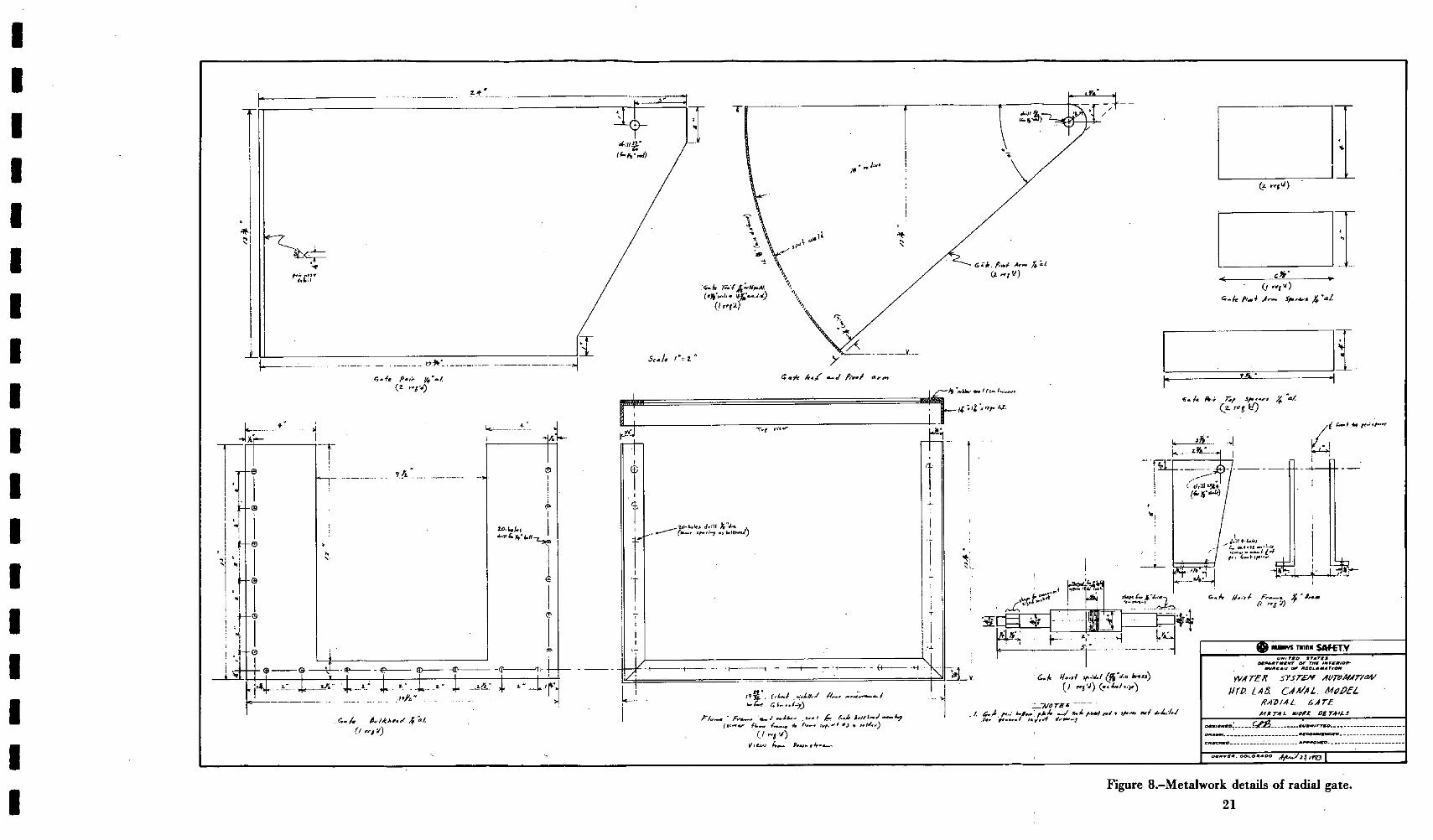
Figure 8 . - M e t a l w o r k detai ls o f radial gate .
21

m CENTRAL AREA TELEPHONE ]
m
I I ~ LAB. NO. & I
o. EQUIPMENT" LAYOUT
'
I F ~ : ~ , ( l ~ ! MI~NI [ ~ M A G N E T I C TAPES DISC DRIVE I
. ~ • ICMPTR. °I~
m CARD READER
LAB. NO. 2
COMMUNICATIONS INTERFACE (MODEM) -,HB< COMMUNICATIONS INTERFACES (HARDWIRED) --~B<
---D( ~,r--) <
TO BRANCH TERMINALS
PLOTTER
TAPE PUNCH
¢ ~,4~,& &( 6 BCD INPUTS H, H4H,& ,I,II&ILH, HI,FilH, ,H,H,H,H, H,,H,H&,~
I ~ , ~ ~ COMMUNICATIONS ~' I INTERFACE _ MINI
TO/FROM CENTRAL - - ICMPTR~' I COMPUTER ~ - ~ " J
I ~ N ,,~ ~' HUH iiIHiilll '~(4 & &(, &(, BCD
INPUT FROM TESTS & OUTPUT TO TESTS
>
>
b. CENTRAL AREA EQUIPMENT LOW LEVEL DIFF. INPUTS
u~u = = SINGLE ENOED
]A ~'~* INPUTS ) /D C VERT. ~" "
' - ~ HIGH LEVEL ~_ DIFF. INPUTS
~& H H D/A OUTPUTS
c. BRANCH TERMINAL EQUIPMENT
Figure 9.-Measurement analysis and control computer system.
2 3

I+~
t ~-" +:):: :+-+~:~ : -~++i.
+~+++ + +?+?++i+i~+++~ii!/+++ • ++++ +++?: ++ :+:++++-+++:~ ~ - :+ :5~+ ~++++ +++ .+++ +++ .~ ++++ +,.~ +: ~+++ : i
O 0 0 o o o o
h ,
Figure 10.-Radial gate model. Photo P801-D-75701 NA
H N i i H i H I m l I I I i l / i i

m m m m m m m m m m m m m mm m m m m
ABSTRACT
Facilit ieshave been provided in the Hydraulics Branch Laboratory, Division of General Research, Engineering and Research Center to investigate methods and means of automating and remotely controlling irrigation systems for the Bureau of Reclamation. This report describes these laboratory and field facilities for studying, developing, and demonstrating control methods for automatic flow regulation.
ABSTRACT
Facilities have been provided in the Hydraulics Branch Laboratory, Division of General Research. Engineering and Research Center to investigate methods and means of automating and remotely controlling irrigation systems for the Bureau of Reclamation. This report describes these laboratory and field facilities for studying, developing, and demonstrating control methods for automatic flow regulation.
ABSTRACT
Facilities have been provided in the Hydraulics Branch Laboratory, Division of General Research, Engineering and Research Center to investigate methods and means of automating and remotely controlling irrigation systems for the Bureau of Reclamation. This report describes these laboratory and field facilities for studying, developing, and demonstrating control methods for automatic flow regulation.
ABSTRACT
Facilities have been provided in the Hydraulics Branch Laboratory. Division of General Research, Engineering and Research Center to investigate methods and means of automating and remotely controlling irrigation systems for the Bureau of Reclamation. This report describes these laboratory and field facilities for studying, developing, and demonstrating control methods for automatic flow regulation.

GR-5-77 Schuster, J. C. and Enger, P. F. LABORATORY FACILITIES FOR RESEARCH AND DEVELOPMENT OF WATER SYSTEMS CONTROL AUTOMATION Bur Reclam Rep GR-5-77, Div Gen Res, April 1977 Bureau of Reclamation, Denver, 24 p, 10 fig.
DESCRIPTORS-/automation/hydraulic models/canals/data acquisition/electronics/radial gates/control equipment/ instrumentation/computers
COSATI Field/Group 14B COWRR: 1402
GR-5-77 Schuster, J. C. and Enger, P. F. LABORATORY FACILITIES FOR RESEARCH AND DEVELOPMENT OF WATER SYSTEMS CONTROL AUTOMATION Bur Reclam Rep GR-5-77, Div Gen Res, April 1977 Bureau of Reclamation. Denver, 24 p, 10 fig.
DESCRIPTORS-/automation/hydraulic models/canals/data acquisition/electronics/radial gates/control equipment/ instrumentation/computers
COSATI Field/Group 14B COWRR: 1402
GR-5-77 Schuster, J. C. and Enger, P. F. LABORATORY FACILITIES FOR RESEARCH AND DEVELOPMENT OF WATER SYSTEMS CONTROL AUTOMATION Bur Reclam Rep GR-5-77o Div Gen Res, April 1977 Bureau of Reclamation, Denver, 24 p, 10 fig.
DESCRIPTORS-/automation/hydraulic models/canals/data acquisition/electronics/radial gates/control equipment/ instrumentation/computers
GR-5-77 Schuster, J. C. and Enger, P. F. LABORATORY FACILITIES FOR RESEARCH AND DEVELOPMENT OF WATER SYSTEMS CONTROL AUTOMATION Bur Reclam Rep GR-5-77, Div Gen Res, April 1977 Bureau of Reclamation, Denver, 24 p, 10 fig.
DESCRIPTORS-/automation/hydraulic models/canals/data acquisition/electronics/radial gates/control equipment/ instrumentation/computers
COSATI Field/Group 14B COWRR: 1402 COSATI Field/Group 14B COWRR: 1402
m m mm m m m m mm m m m n m m m m u m