Embed Size (px)
Citation preview
Laboratory Assessment of Energy-Efficiency in Vibratory Compaction of Granular Materials
Federico Fernández Geofed, Ottawa, Ontario, Canada
Garrett Osborne Algonquin College, Ottawa, Ontario, Canada ABSTRACT Laboratory testing equipment was customized to assess energy-efficiency in the compaction of granular materials using a vibratory hammer. During the compaction process, the density growth is derived by tracking the downwards displacement of the tamper in contact with the surface of a constant mass of granular material contained in a standard compaction (Proctor) mold. The energy used during the compaction process is estimated as the product of the elapsed compaction time and the impact power rated by the manufacturer of the vibratory hammer. The graphic representation of density versus the cumulative energy consumed during the compaction test produces a density growth curve. Energy-efficient compaction is achieved when the desired state of compactness is reached at the expense of lesser energy. The paper describes a laboratory test method used to evaluate both the compactibility and the maximum density attainable by the vibratory compaction process. This approach can be used in support of sustainable earthwork construction practices to guide the optimal selection of compaction variables such as vibratory frequency, surcharge or lift characteristics. RÉSUMÉ L'équipement d'essai de laboratoire a été personnalisé pour évaluer l'efficacité énergétique du compactage de matériaux granulaires utilisant un vibrofonceur. Durant le processus de compactage, la croissance de la densité a été dérivée par la continuité du déplacement vers le bas de la plaque vibrante avec l'appui constant d'une masse de matériaux granulaires contenus dans un moule standard de compactage (Proctor). L'énergie utilisée durant le processus de compactage est estimée par le produit du temps écoulé pour le compactage et la puissance de l'impact évaluée par le fabricant du vibrofonceur. La représentation graphique de la masse volumique selon l'énergie cumulative consommée durant le test de compactage produit la courbe de croissance de la masse volumique. Un compactage écoénergétique est réalisé lorsque l'état souhaité de compacité est atteint en utilisant moins d'énergie. L'étude décrit une méthode d’essai en laboratoire qui a pour but d'évaluer la compactibilité ainsi que la densité maximale réalisable avec le processus de compactage avec vibration. Cette approche peut être utilisée en s'appuyant sur les pratiques de la construction du terrassement durable pour guider la sélection optimale des variables de compactage, telles que la fréquence vibratoire, la pression de confinement ou les caractéristiques de la couche. 1 INTRODUCTION The laboratory assessment of soil compaction in earthworks is normally conducted by relating field and laboratory compaction performances. A target degree of compaction is established depending on the desired performance and the earthworks are tested during field compaction to ensure that the target level is met. The result-based approach is primarily focussed on achieving the target degree of compaction without regard for the efficiency of the process. Fernandez and Corcoran (2001) introduced an analytical model for assessing soil compaction efficiency and a laboratory test method for assessing the efficiency of dynamic compaction was presented by Fernandez (2013).
The present paper describes a laboratory test method for assessing the process of vibratory compaction based on the model by Fernandez and Corcoran (2001).
1.1 The Proctor test The Proctor laboratory test has been the basis of a widely used approach for assessing the efficacy of earthworks compaction. The compaction characteristics are determined as the water content versus density relationship after a prescribed compactive effort is applied to the tested soil. The resulting compactive effort (E) is determined by Equation [1].
E = (M H N L) ÷ V [1]
A mold of fixed volume (V) is filled with the test soil placed in a number of loose layers (L) and subjected to the dynamic energy delivered by a rammer of known mass (M) dropped from a given height (H) for a specified number of blows (N).
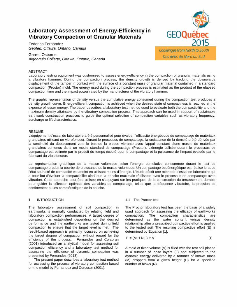
1.2 Standard Proctor test The standard Proctor test determines a two-dimensional (2D) relation between water content and soil density for a fixed compactive effort of 600 kJ/m3 (12,400 lbf-ft/ft3
). The specific parameters for the 4-inch and 6-inch diameter molds are indicated in the following Table 1:
Table 1. Compactive Effort for Standard Proctor Test
1.3 Modified Proctor test The modified Proctor test determines the 2D relationship between water content and soil density for a compactive effort of 2,700 kJ/m3 (56,000 lbf-ft/ft3
) as shown in Table 2 for the 4-inch and 6-inch diameter molds:
Table 2. Compactive Effort for Modified Proctor Test
2 SOIL COMPACTION MODEL The Proctor test results are normally graphed producing a “bell-shaped” compaction curve relating dry density and water content. This 2D analysis yields a Maximum Dry Density (ρd
max) corresponding to the Optimum Water
Content (woptFernandez and Corcoran (2001) introduced a three-
dimensional (3D) analytical model based on fundamental variables of soil compaction: dry density (ρ
).
d
A typical set of compaction and density growth curves produced by the model is illustrated in Figure 1 and described in the following subsections.
), water content (w) and compactive effort or energy (E).
2.1 Compaction Curve Figure 1a shows the typical “bell-shape” compaction curve relating dry density and water content within the compactible range of soil moisture referred to by Li and Sego (1999). The compaction curve reaches a maximum dry density corresponding to the optimum water content.
Figure 1a (above) and Figure 1b (below). Typical Compaction Model Graphs 2.2 Density Growth Curve Figure 1b shows a typical density growth curve where the dry density increases from a loose (uncompacted) value as the compactive effort (energy) increases in accordance with the following exponential equation: ρd = ρd min + (ρd max – ρd min) (1 – 10
-KE
) [2]
where,
ρd min = Uncompacted or loose dry density (Mg/m3
ρ or pcf)
d max energy (Mg/m
= Maximum dry density, corresponding to infinite 3
E = Energy or compactive effort (kN-m/m or pcf)
3 or lbf-ft/ft3 K = Compactibility (m
) 3/kN-m or ft3/lbf
-ft)
The density growth curve provides a graphic description of the evolution of the soil compaction process, which is typically characterized by a steep

increase in density followed by diminishing rates of density growth at increasing compactive efforts. 2.3 Evaluation of the Soil Compaction Process
The density growth curves created by Equation [2] provide a convenient means to evaluate the soil compaction process in terms of effectiveness and efficiency. The process effectiveness is defined as the ability to reach the target degree of compaction and it is related to the maximum dry density (ρdmax
Figure 2 illustrates a series of density growth curves for a soil with a loose dry density ρ
). The energy-efficiency of the process is directly reflected by the compactibility (K).
dmin = 80 pcf (1.28 Mg/m3) being compacted to a target dry density of 135 pcf (2.16 Mg/m3
The density growth curves in Figure 2a have a maximum dry density ρ
).
dmax = 140 pcf (2.24 Mg/m3) and both curves are effective in reaching the target density. The figure also shows higher energy-efficiency for the solid line curve (K = 1x10⁻⁴ m3/kN-m) relative to the dashed line curve (K = 2x10⁻⁵ m3
/kN-m). The energy-efficiency is evidenced by the solid line curve reaching the target density while only consuming about one-fifth of the energy required by the dashed curve.
Figure 2a (above) and Figure 2b (below).
2.4 Process Effectiveness and Efficiency
The density growth curves in Figure 2b have a maximum dry density ρdmax = 130 pcf (2.08 Mg/m3) and therefore both curves are ineffective in reaching the target density of 135 pcf (2.16 Mg/m3). In addition, the dashed curve (K = 2x10⁻⁵ m3/kN-m) is inefficient relative to the solid line curve (K = 1x10⁻⁴ m3
It has been illustrated in Figure 2 that both parameters in Equation [2], K and ρ
/kN-m).
d max
, can be used as indicators in order to optimize process variables such as water content, lift thickness and mode of compaction.
3 EXPERIMENTAL PROGRAM
A laboratory testing program was conducted to assess the process of vibratory compaction. The test samples consisted of commercially available “Sakrete Standard Concrete Mix” material used by Osborne et al (2015) in the laboratory assessment of Roller-Compacted Concrete (RCC).
The testing program included Standard and Modified Proctor tests (ASTM D698 and D1557) as well as a series of vibratory compaction tests conducted using equipment specially designed to monitor the process of density growth. 3.1 Test Materials
The laboratory testing was conducted using “Sakrete Standard Concrete Mix” commercially supplied in 30 kg (66 lbs) bags. The Sakrete mix provided a consistent mixture of sand, coarse aggregate and cement for conveniently preparing specimens with minimal variability in the mixture. Figure 3 shows the particle size distribution for aggregates in the Sakrete mix determined by sieve analysis and corrected for the removal of 6% cement content.
Figure 3. Aggregate Size Distribution of Sakrete mix
The Sakrete mix aggregates are classified as well-graded sand with silt (SW-SM) in accordance with the Unified Soil Classification System (USCS). As illustrated in Figure 3, the texture of the aggregates in the Sakrete mix material consists of 36.2% gravel, 54.7% sand and 9.0% fines.
3.2 Proctor Compaction Tests
Standard and modified proctor tests (ASTM D698 and ASTM D1557) were conducted to determine the relation between water content and soil density for fixed levels of compactive effort.
3.3 Vibratory Test Equipment
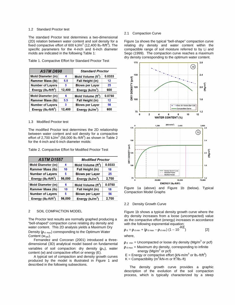
Figure 4 illustrates the vibratory system that was specially designed to assess the vibratory compaction process in a controlled laboratory environment. The system can substantially comply with standardized test methods (ASTM C1435 and ASTM D7382) while enabling the continuous monitoring of the density growth curve (density vs. energy) during the compaction process.
Figure 4. Vibratory Energy Test Assembly
The system is shown in Figure 4a and consists of a solid pedestal that firmly supports the compaction frame in order to prevent the loss of energy during compaction. The compaction frame includes top and bottom aluminum plates, connected by three vertical steel rods. The upper plate supports the vibratory hammer in the vertical position and is guided by linear bearings around the three steel rods that allow for free vertical movement during compaction. The hammer can be raised or lowered into position by the cable winch that provides a quick detach to initiate the compaction process. The weight of the hammer and assembly applies a fixed level of surcharge pressure to the compacted material. By simply adding additional weights to the hammer assembly, the surcharge pressure can be increased.
Figure 4b shows the vibratory shaft assembly for the tamping plates that fit 4-inch and 6-inch standard molds. The test assembly was customized for continuously monitoring the sinkage of the tamping plate into the test material placed in the mold. The sinkage guide (Figure 4c) consists of a measuring tape attached to the compaction frame and a reference crosshair line at the edge of the upper aluminum plate. Figure 4c shows a displacement
reading of 55.3mm and the displacement of the tamping plate can be tracked throughout the test using a video capturing device.
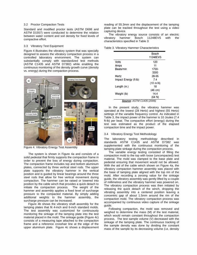
The vibratory energy source consists of an electric vibratory hammer Bosch 11248EVS with the characteristics specified in Table 3:
Table 3. Vibratory Hammer Characteristics
Source
: ASTM C1435 (2006)
In the present study, the vibratory hammer was operated at the lowest (28 Hertz) and highest (55 Hertz) settings of the variable frequency control. As indicated in Table 3, the impact power of the hammer is 10 Joules (7.4 ft-lb) per beat. The compactive effort (energy) during the test was estimated as the product of the elapsed compaction time and the impact power. 3.4 Vibratory Energy Test Methodology
The laboratory testing methodology described in standards ASTM C1435 and ASTM D7382 was supplemented with the continuous monitoring of the tamping plate sinkage during the compaction process.
The variable energy testing consisted of filling the compaction mold to the top with loose (uncompacted) test material. The mold was clamped to the base plate and pedestal ensuring that movement would not be allowed. With the aid of the cable winch shown on Figure 4a, the vibratory compaction hammer assembly was placed with the base of tamping plate aligned with the top rim of the mold. After recording a zeroing value for the sinkage guide, the vibratory assembly was gently lifted by a couple of millimetres and the vibratory hammer was powered on. The vibratory compaction process was then initiated by releasing the quick detach of the winch, dropping the vibrating assembly into a centered position leaving a concentric gap of about 1.5mm around the rim of the compaction mold. The vibratory compaction process was accompanied by continuous video capture of the sinkage guide.
Following compaction, the mold was removed and weighed to determine the mass (M) of the test material, which would remain constant throughout the compaction process. The test sample volume (V) decreased with the sinkage of the tamping plate. The continuous tracking of the sample density was done by dividing the constant mass of the sample by its decreasing volume (i.e, density
= M/V). The compactive effort (E) was also tracked continuously by multiplying the unit impact energy of 10 Joules (7.4 ft-lb) by the number of beats resulting from the product of elapsed time and selected frequency. For example, the tests conducted at a frequency of 28 Hertz (i.e. 28 beats per second) imparted a vibratory energy of 280 Joules per second of vibration (i.e. 280 Watts). Tests conducted at a frequency of 55 Hertz imparted a compactive effort of 550 Watts (i.e. 10 Joules x 55 Hertz).
The variable energy test methodology allows for continuous monitoring of the evolution of the density growth curve during the laboratory vibratory compaction process. 4 TEST RESULTS
The following subsections present the results of Proctor compaction tests conducted on samples of “Sakrete Standard Concrete Mix” material. 4.1 Density-Moisture Relationship from Proctor Tests
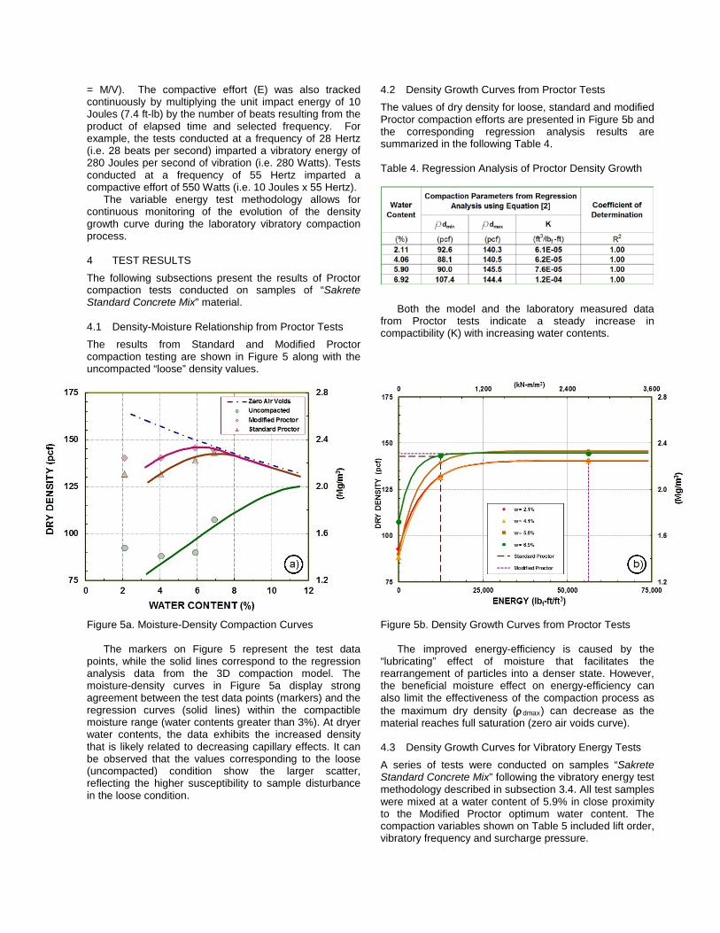
The results from Standard and Modified Proctor compaction testing are shown in Figure 5 along with the uncompacted “loose” density values.
Figure 5a. Moisture-Density Compaction Curves
The markers on Figure 5 represent the test data points, while the solid lines correspond to the regression analysis data from the 3D compaction model. The moisture-density curves in Figure 5a display strong agreement between the test data points (markers) and the regression curves (solid lines) within the compactible moisture range (water contents greater than 3%). At dryer water contents, the data exhibits the increased density that is likely related to decreasing capillary effects. It can be observed that the values corresponding to the loose (uncompacted) condition show the larger scatter, reflecting the higher susceptibility to sample disturbance in the loose condition.
4.2 Density Growth Curves from Proctor Tests
The values of dry density for loose, standard and modified Proctor compaction efforts are presented in Figure 5b and the corresponding regression analysis results are summarized in the following Table 4. Table 4. Regression Analysis of Proctor Density Growth
Both the model and the laboratory measured data
from Proctor tests indicate a steady increase in compactibility (K) with increasing water contents.
Figure 5b. Density Growth Curves from Proctor Tests
The improved energy-efficiency is caused by the “lubricating” effect of moisture that facilitates the rearrangement of particles into a denser state. However, the beneficial moisture effect on energy-efficiency can also limit the effectiveness of the compaction process as the maximum dry density (ρdmax
) can decrease as the material reaches full saturation (zero air voids curve).
4.3 Density Growth Curves for Vibratory Energy Tests
A series of tests were conducted on samples “Sakrete Standard Concrete Mix” following the vibratory energy test methodology described in subsection 3.4. All test samples were mixed at a water content of 5.9% in close proximity to the Modified Proctor optimum water content. The compaction variables shown on Table 5 included lift order, vibratory frequency and surcharge pressure.
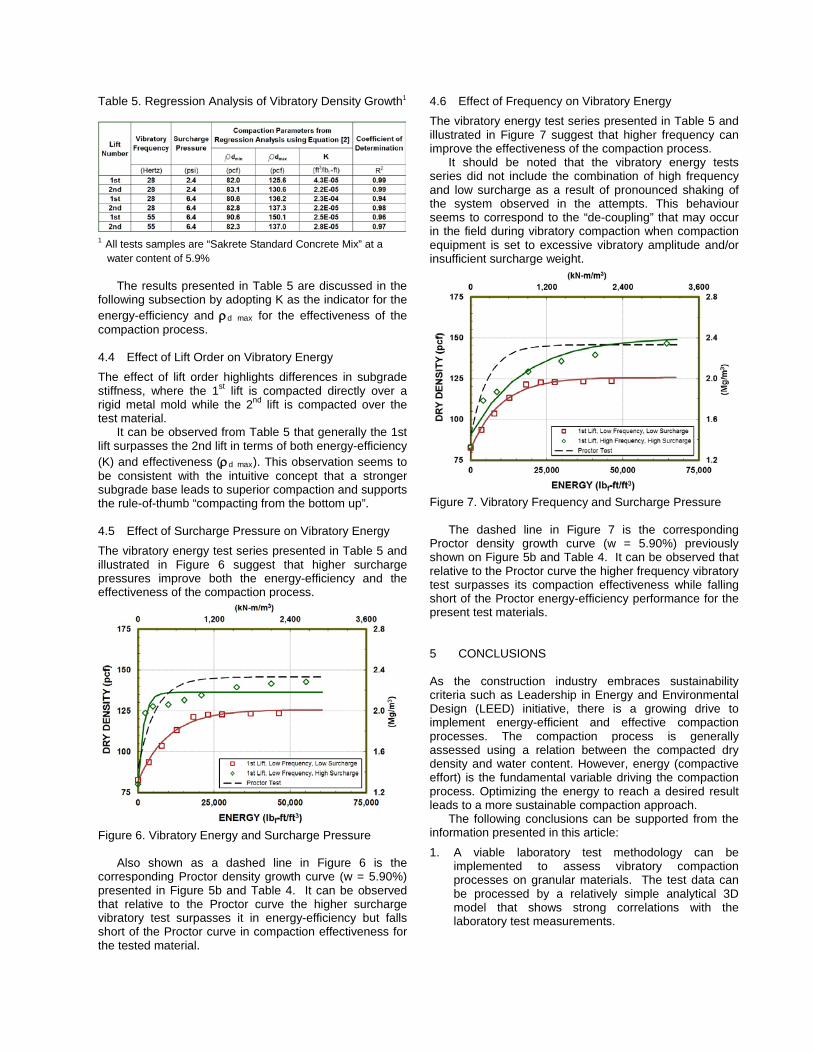
Table 5. Regression Analysis of Vibratory Density Growth
1
1
water content of 5.9% All tests samples are “Sakrete Standard Concrete Mix” at a
The results presented in Table 5 are discussed in the
following subsection by adopting K as the indicator for the energy-efficiency and ρd
max
for the effectiveness of the compaction process.
4.4 Effect of Lift Order on Vibratory Energy
The effect of lift order highlights differences in subgrade stiffness, where the 1st lift is compacted directly over a rigid metal mold while the 2nd
It can be observed from Table 5 that generally the 1st lift surpasses the 2nd lift in terms of both energy-efficiency (K) and effectiveness (ρ
lift is compacted over the test material.
d max
). This observation seems to be consistent with the intuitive concept that a stronger subgrade base leads to superior compaction and supports the rule-of-thumb “compacting from the bottom up”.
4.5 Effect of Surcharge Pressure on Vibratory Energy
The vibratory energy test series presented in Table 5 and illustrated in Figure 6 suggest that higher surcharge pressures improve both the energy-efficiency and the effectiveness of the compaction process.
Figure 6. Vibratory Energy and Surcharge Pressure
Also shown as a dashed line in Figure 6 is the corresponding Proctor density growth curve (w = 5.90%) presented in Figure 5b and Table 4. It can be observed that relative to the Proctor curve the higher surcharge vibratory test surpasses it in energy-efficiency but falls short of the Proctor curve in compaction effectiveness for the tested material.
4.6 Effect of Frequency on Vibratory Energy
The vibratory energy test series presented in Table 5 and illustrated in Figure 7 suggest that higher frequency can improve the effectiveness of the compaction process.
It should be noted that the vibratory energy tests series did not include the combination of high frequency and low surcharge as a result of pronounced shaking of the system observed in the attempts. This behaviour seems to correspond to the “de-coupling” that may occur in the field during vibratory compaction when compaction equipment is set to excessive vibratory amplitude and/or insufficient surcharge weight.
Figure 7. Vibratory Frequency and Surcharge Pressure
The dashed line in Figure 7 is the corresponding Proctor density growth curve (w = 5.90%) previously shown on Figure 5b and Table 4. It can be observed that relative to the Proctor curve the higher frequency vibratory test surpasses its compaction effectiveness while falling short of the Proctor energy-efficiency performance for the present test materials. 5 CONCLUSIONS As the construction industry embraces sustainability criteria such as Leadership in Energy and Environmental Design (LEED) initiative, there is a growing drive to implement energy-efficient and effective compaction processes. The compaction process is generally assessed using a relation between the compacted dry density and water content. However, energy (compactive effort) is the fundamental variable driving the compaction process. Optimizing the energy to reach a desired result leads to a more sustainable compaction approach.
The following conclusions can be supported from the information presented in this article:
1. A viable laboratory test methodology can be implemented to assess vibratory compaction processes on granular materials. The test data can be processed by a relatively simple analytical 3D model that shows strong correlations with the laboratory test measurements.

2. Optimal compaction processes can be defined and evaluated using laboratory testing methodologies that enhance the standard Proctor testing. The vibratory energy test allows for continuous monitoring of the density and compactive effort during the entire compaction process.
3. Characterizing the interrelationships between the soil
moisture, compactive effort and dry density is a necessary requirement for implementing a sustainable design of compaction.
4. The vibratory energy laboratory compaction method provides a convenient and effective determination of compactibility (K) and maximum dry density (ρd
max
). These two parameters can serve as indicators for selecting process variables to produce energy-efficiency and effective compaction.
5. The test results for the samples of “Sakrete Standard Concrete Mix” indicate that the combination of high surcharge and high vibratory frequency produced the most sustainable compaction process.
In summary, compacting in conditions conducive to
optimize effectiveness and energy-efficiency can significantly improve compaction productivity, conserve non-renewable resources and reduce environmental impacts in support of sustainable earthwork construction. ACKNOWLEDGEMENTS The authors would like to acknowledge the contribution of Algonquin Centre for Construction Excellence (ACCE) for providing temporary storage space for the test materials and equipment used in this research project. REFERENCES ASTM D698, 2012. Standard Test Methods for Laboratory
Compaction Characteristics of Soil Using Standard Effort (12,400 ft-lbf/ft3 (600 kN-m/m3)). American Society for Testing and Materials
, ASTM, West Conshohocken, PA, USA
ASTM C1435, 2006. Standard Practice for Molding Roller-Compacted Concrete in Cylinder Molds Using a Vibrating Hammer. American Society for Testing and Materials
, ASTM, West Conshohocken, PA, USA.
ASTM D1557, 2012. Standard Test Methods for Laboratory Compaction Characteristics of Soil Using Modified Effort (56,000 ft-lbf/ft3 (2,700 kN-m/m3)). American Society for Testing and Materials
, ASTM, West Conshohocken, PA, USA.
ASTM D7382, 2008. Standard Test Method for Determination of Maximum Dry Density and Water Content for Effective Compaction of Granular Soils Using a Vibrating Hammer. American Society for Testing and Materials
, ASTM, West Conshohocken, PA, USA.
Drnevich, V.P., Evans, A.C and A.B. Prochaska,. 2007. A Study of Effective Soil Compaction Control of Granular Soils. FHWA/IN/JTRP-2007/12 Joint Transportation Research Program, Indiana Dept. of Transportation and Purdue University, West Lafayette, Indiana. doi:10.5703/1288284313357.
Fernandez, F. 2013. Assessing Energy-Efficiency in Soil
Compaction, Proceedings of the 66th Canadian Geotechnical Conference, Montreal, Canada 2013
, Paper 366.
Fernandez, F and Corcoran, P.T. 2001. A Concept for Assessing Soil Compaction Efficiency, ASCE Geotechnical Special Publication #113, 325-339.
Li H., and Sego, D.C. 1999. Equation for Complete
Compaction Curve of Fine-grained Soils and its Applications, ASTM SPT 1384,113-125.
Osborne, G., Truong. T.D., Costantini. C. and R. Dixon-
Shecapio. 2015. Laboratory Assessment of Roller-Compacted Concrete. Final Report for ENG4003 Algonquin College Civil Engineering Technology. Algonquin Centre for Construction Excellence. Ottawa, ON, Canada