Embed Size (px)
Citation preview
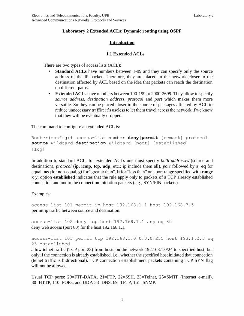
Electronics and Telecommunications Faculty, UPB Laboratory 2 Advanced Communications Networks, Protocols and Services
1
Laboratory 2 Extended ACLs; Dynamic routing using OSPF
Introduction
1.1 Extended ACLs
There are two types of access lists (ACL):
• Standard ACLs have numbers between 1-99 and they can specify only the source
address of the IP packet. Therefore, they are placed in the network closer to the
destination affected by ACL based on the idea that packets can reach the destination
on different paths.
• Extended ACLs have numbers between 100-199 or 2000-2699. They allow to specify
source address, destination address, protocol and port which makes them more
versatile. So they can be placed closer to the source of packages affected by ACL to
reduce unnecessary traffic: it’s useless to let them travel across the network if we know
that they will be eventually dropped.
The command to configure an extended ACL is:
Router(config)# access-list number deny|permit [remark] protocol
source wildcard destination wildcard [port] [established]
[log]
In addition to standard ACL, for extended ACLs one must specify both addresses (source and
destination), protocol (ip, icmp, tcp, udp, etc.; ip include them all), port followed by a: eq for
equal, neq for non-equal, gt for “greater than”, lt for “less than” or a port range specified with range
x y; option established indicates that the rule apply only to packets of a TCP already established
connection and not to the connection initiation packets (e.g., SYN/FIN packets).
Examples:
access-list 101 permit ip host 192.168.1.1 host 192.168.7.5
permit ip traffic between source and destination.
access-list 102 deny tcp host 192.168.1.1 any eq 80
deny web access (port 80) for the host 192.168.1.1.
access-list 103 permit tcp 192.168.1.0 0.0.0.255 host 193.1.2.3 eq
23 established
allow telnet traffic (TCP port 23) from hosts on the network 192.168.1.0/24 to specified host, but
only if the connection is already established, i.e., whether the specified host initiated that connection
(telnet traffic is bidirectional). TCP connection establishment packets containing TCP SYN flag
will not be allowed.
Usual TCP ports: 20=FTP-DATA, 21=FTP, 22=SSH, 23=Telnet, 25=SMTP (Internet e-mail),
80=HTTP, 110=POP3, and UDP: 53=DNS, 69=TFTP, 161=SNMP.
Electronics and Telecommunications Faculty, UPB Laboratory 2 Advanced Communications Networks, Protocols and Services
2
As with the standard ACL, the extended ACL must be placed on a router interface with the
command:
ip access-group number_ACL in|out
Due to the existence of two pairs address / wildcard mask versus one pair to standard, the extended
ACL the default rule that exists at the end it is deny ip any any (instead of deny any). If
one would want to implement the implicit behavior that allow all traffic, the rule to be written last
is permit ip any any.
1.2 OSPF protocol. Introduction.
OSPF (Open Shortest Path First) routing protocol is a dynamic routing protocol of type link-
state unlike RIP and IGRP who are distance-vector type. This means that all routers know the
complete topology of the network and routing decisions can be made without risk of generating
loops in the network. The metric used is based on a cost that is usually available band on each link,
while the RIP metric was given by the number of hops (this means that the RIP will preferred a
direct path between two nodes on a low speed link instead of an indirect path, with an intermediate
node, but on a Gigabit Ethernet link). Another advantage of OSPF is the larger number of hops
supported (255 to 15) which allows operation in midsize / large networks.
Like RIP, OSPF protocol is based on a standard (open) so it is possible to interplay among
several manufacturers of routers. The algorithm for determining the minimum distance between any
two nodes (shortest path) is Dijkstra's algorithm.
RIP and OSPF are interior routing protocols, that are used within an area under a common
administration. One such area is called AS (Autonomous System). Routes, protocols, routing policies
and the other technical and administrative aspects are defined in a uniform manner and are under
the control of AS. By comparison, there are exterior routing protocols (e.g., BGP) that are used
between different AS.
Interior routing protocols are called IGP (interior gateway protocol) and outer are called
EGP (exterior gateway protocols).
In terms of operation, OSPF is significantly more complex than RIP. Routing messages
exchanged between routers are called LSA (Link State Advertisements). A router sends in LSA
information such as the state of its links with the other connected routers (link states). Based on
LSA messages each router creates a table (link state database) containing the network topology.
These tables should be the same for all routers in the network (or, as we shall see, even within a
country). Applying SPF algorithm on this table, each router obtains minimum cost routes to all
destinations in the table, which forms routing table (routing table).
To reduce the number of LSA in large networks the concept of area is used. An area
represents a certain part of the network (Cisco recommends less than 50 routers in an area, but one
can use much smaller areas, too - depending on the speed of available connections and the routers’
computation power). There is an area called the Backbone Area - the area that binds all other areas,
if any. It is mandatory numbered as Area 0, while the other areas can be numbered anyway. Link
state information are identical only within an area. Link state information on interior routers are not
transfer outside the area, but only information about edge routers (Area Border Routers), making
OSPF AS scalable in large networks.
Electronics and Telecommunications Faculty, UPB Laboratory 2 Advanced Communications Networks, Protocols and Services
3
1.3 Chosing DR/BDR
A router creates a table with all its directly connected neighbors called Adjacency Database.
In the case of a point-to-point network such as serial networks, who have exactly 2 nodes, it is
obvious that each router has only one neighbor on each such network. But there are broadcast
networks (the messages are broadcasted to many nodes) such as Ethernet networks that can connect
directly many nodes. To minimize the number of LSA on such a network a designated router, DR
(Designated Router), and a "reserve" called BDR (Backup Designated Router) are chosen. Only the
designated router is receiving / disseminating routing information from / to other routers in the other
networks.
Choosing a DR / BDR is done on all broadcast networks, even if there are only two routers
in such a network and even when there is one (and other nodes are PCs that do not participate in the
routing process). The choice is based on two numerical values:
• router ID,
• priority – at the interface level.
If there is not a manually configured router ID, the router chooses highest IP address
(number of 32-bit) of the existing router interfaces. If there are loopback interfaces, the one with
the bigger IP address is chosen, even if its IP is less than the IP of a non-loopback interfaces. This
is because the loopback interfaces are stable (do not become "down" due to disconnection of a cable,
for example).
Priority of each interface is one by default and can be changed manually between 0 and 255.
The priority is considered at the interface level because a router can connect to multiple broadcast
networks if it has more interfaces; in each network, it could have a different status -in a network
could be DR, while in other not.
The process of choosing the network is as follows:
• router with the highest priority becomes the DR and BDR becomes the next. Priority
0 means that the router cannot be DR.
• In case of equal priorities, the election is based on router ID.
1.4 Wildcard mask in OSPF
Even if the OSPF operation is fundamentally different of RIP, within a single zone the
configuration is very similar. A notable difference is the use of wildcard mask to define networks.
A wildcard mask (like that used in ACL) is a 32-bit number that allows "masking" or more precisely
"selection" of certain bits of an IP address that you specify the desired network. The rule is: for a
bit of the address that is selected, the position in the mask must be "0". So "0" has the meaning
"Check" and "1" has the meaning "Ignore".
In OSPF is noted that wildcard mask is the inverse of netmask. For example, a class C
network 192.168.1.0/24 has the wildcard mask 255.255.255.0 while the netmask is 0.0.0.255.
Similarly, a network 192.168.100.128/26 with the wildcard mask 255.255.255.192 has the netmask
0.0.0.63 (last byte is 11,000,000 in the netmask and 00,111,111 in the wildcard mask).
Electronics and Telecommunications Faculty, UPB Laboratory 2 Advanced Communications Networks, Protocols and Services
4
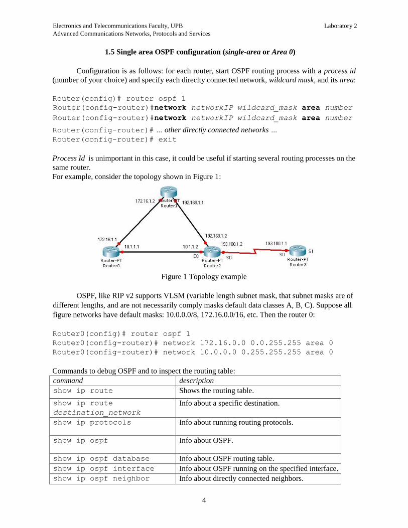
1.5 Single area OSPF configuration (single-area or Area 0)
Configuration is as follows: for each router, start OSPF routing process with a process id
(number of your choice) and specify each direclty connected network, wildcard mask, and its area:
Router(config)# router ospf 1
Router(config-router)#network networkIP wildcard_mask area number
Router(config-router)#network networkIP wildcard_mask area number
Router(config-router)# … other directly connected networks …
Router(config-router)# exit
Process Id is unimportant in this case, it could be useful if starting several routing processes on the
same router.
For example, consider the topology shown in Figure 1:
Figure 1 Topology example
OSPF, like RIP v2 supports VLSM (variable length subnet mask, that subnet masks are of
different lengths, and are not necessarily comply masks default data classes A, B, C). Suppose all
figure networks have default masks: 10.0.0.0/8, 172.16.0.0/16, etc. Then the router 0:
Router0(config)# router ospf 1
Router0(config-router)# network 172.16.0.0 0.0.255.255 area 0
Router0(config-router)# network 10.0.0.0 0.255.255.255 area 0
Commands to debug OSPF and to inspect the routing table:
command description
show ip route Shows the routing table.
show ip route
destination_network
Info about a specific destination.
show ip protocols Info about running routing protocols.
show ip ospf Info about OSPF.
show ip ospf database Info about OSPF routing table.
show ip ospf interface Info about OSPF running on the specified interface.
show ip ospf neighbor Info about directly connected neighbors.
Electronics and Telecommunications Faculty, UPB Laboratory 2 Advanced Communications Networks, Protocols and Services
5
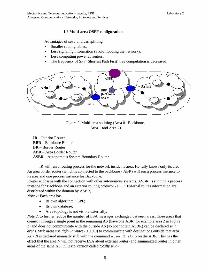
1.6 Multi-area OSPF configuration
Advantages of several areas splitting:
Smaller routing tables;
Less signaling information (avoid flooding the network);
Less computing power at routers;
The frequency of SPF (Shortest Path First) tree computation is decreased.
Figure 2. Multi-area splitting (Area 0 –Backbone,
Area 1 and Area 2)
IR – Interior Router
BBR – Backbone Router
BR – Border Router
ABR – Area Border Router
ASBR – Autonomous System Boundary Router
IR will run a routing process for the network inside its area; He fully knows only its area.
An area border router (which is connected to the backbone - ABR) will run a process instance to
its area and one process instance for Backbone.
Router is charge with the connection with other autonomous systems, ASBR, is running a process
instance for Backbone and an exterior routing protocol - EGP (External routes information are
distributed within the domain by ASBR).
Note 1: Each area has:
Its own algorithm OSPF;
Its own database;
Area topology is not visible externally.
Note 2: to further reduce the number of LSA messages exchanged between areas, those areas that
connect through a single point in the remaining AS (have one ABR, for example area 2 in Figure
2) and does not communicate with the outside AS (so not contain ASBR) can be declared stub
areas. Stub areas use default routes (0.0.0.0) to communicate with destinations outside that area.
Aria N is declared manually stub with the command area N stub on the ABR. This has the
effect that the area N will not receive LSA about external routes (and summarized routes in other
areas of the same AS, in Cisco version called totally stub).
Electronics and Telecommunications Faculty, UPB Laboratory 2 Advanced Communications Networks, Protocols and Services
6
Configurations:
A. Setting up the router within the area is done as for single-area OSPF (section 1.5).
B. Setting up the router that connects two or more areas each other (areas belonging to the same
AS) is done by configuring the interfaces to operate in corresponding areas.
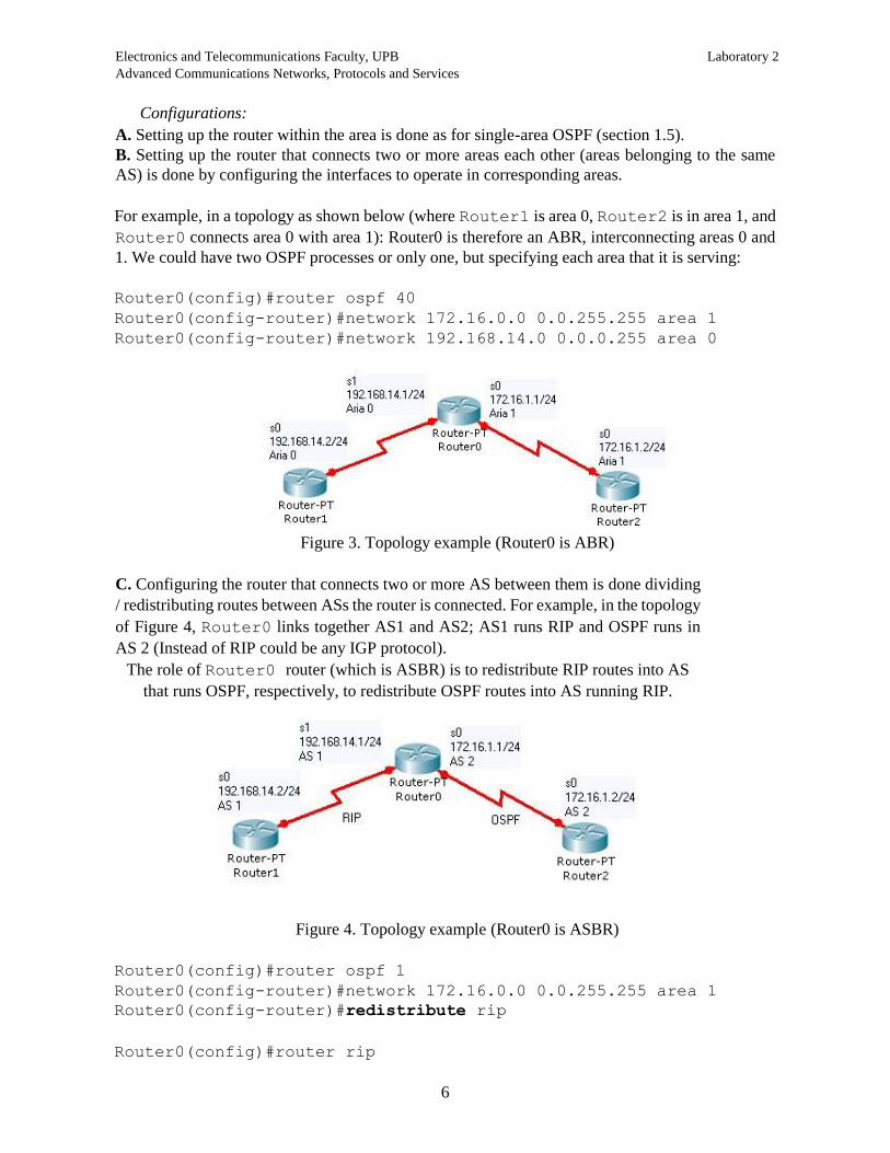
For example, in a topology as shown below (where Router1 is area 0, Router2 is in area 1, and
Router0 connects area 0 with area 1): Router0 is therefore an ABR, interconnecting areas 0 and
1. We could have two OSPF processes or only one, but specifying each area that it is serving:
Router0(config)#router ospf 40
Router0(config-router)#network 172.16.0.0 0.0.255.255 area 1
Router0(config-router)#network 192.168.14.0 0.0.0.255 area 0
Figure 3. Topology example (Router0 is ABR)
C. Configuring the router that connects two or more AS between them is done dividing
/ redistributing routes between ASs the router is connected. For example, in the topology
of Figure 4, Router0 links together AS1 and AS2; AS1 runs RIP and OSPF runs in
AS 2 (Instead of RIP could be any IGP protocol).
The role of Router0 router (which is ASBR) is to redistribute RIP routes into AS
that runs OSPF, respectively, to redistribute OSPF routes into AS running RIP.
Figure 4. Topology example (Router0 is ASBR)
Router0(config)#router ospf 1
Router0(config-router)#network 172.16.0.0 0.0.255.255 area 1
Router0(config-router)#redistribute rip
Router0(config)#router rip

Electronics and Telecommunications Faculty, UPB Laboratory 2 Advanced Communications Networks, Protocols and Services
7
Router0(config-router)#network 192.168.14.0
Router0(config-router)#redistribute ospf 1
Commands to display info about routing tables on ABR or ASBR:
command description
show ip ospf border-router Displays routing table of ABR.
show ip ospf process-id Info about the areas a router is connected.
show ip ospf database summary Displays information only about the summary LSAs.
show ip ospf database asbr-
summary
Displays information only about the autonomous
system boundary router summary LSAs.
show ip ospf database external Displays information about external LSAs.
show ip ospf database
databasesummary
Displays how many of each type of LSA for each area
there are in the database, and the total.
1.7 Summarization
Recall that the summarization means bundling of several routes / destinations into one (n
routes within a specific area are perceived outside that area as one route). This requires continuous
addressing space in that area - as in the case RIPv2, if subnets of the same net are randomly
distributed across multiple routers, one cannot make summarization.
OSPF summarization types:
External summarization:
Autonomous systems AS (by administrative, economic or security reasons) do not transmit
internal routing information completely to other autonomous systems that are connected via an
ASBR router, but only a summary thereof, enough to inform on each network of AS. Whenever
possible, the subnets composing a network are combined into a single network.
ASBR router has the task of summarizing routes to subnets within an AS to which it is connected.
Use the command:
ASBR(config)# router ospf 1
ASBR(config-router)#summary-address address mask
where address and mask specify the super-network (the summarized network).
If we combine the subnets 10.10.1.0/24, 10.10.2.0/24, …, 10.10.255.0/24 in the super-network
10.10.0.0/16, the command is:
ASBR(config-router)#summary-address 10.10.0.0 255.255.0.0
Inter-area summarization:
Summarization can be used between the areas within an AS. The command is:

Electronics and Telecommunications Faculty, UPB Laboratory 2 Advanced Communications Networks, Protocols and Services
8
ABR(config)# router ospf 1
ABR(config-router)#area id range address mask
where address and mask specify the super-network, and id is the area identifier. For example,
for the ABR located at the border between areas 1 and 0, if the subnets are in area 1, the summarized
network is injected in area 0 with the command:
ABR(config-router)#area 1 range 10.10.0.0 255.255.0.0
Part 2. Practice
Figure 5. Test topology
1) Implement the topology in Figure 5, configuring on each router:
- hostname
- IP addresses (including loopbacks)
- Clockrate on DCE end for serial interfaces - 64000
- no shutdown on interfaces
Step 1: OSPF configuration
2) Once configuration is complete, ping test each link and, if successful, save the current
configuration in NVRAM using the copy run start command. To stop a ping that does not
work use CTRL SHIFT 6 sequence.
3) Start the process of OSPF routing with ID 1 on each router (all routers will be in Area 0) such
that ping command will work between any two interfaces.
Q1. Write the networks and wildcard masks configured on each router.
4) Check on R1 the links status with sh ip ospf neighbor; if the link is not working the
adjacency between OSPF routers was not done, and therefore did not include the link in question
in the routing table (indicating a problem).

Electronics and Telecommunications Faculty, UPB Laboratory 2 Advanced Communications Networks, Protocols and Services
9
Q2. Which is the state for each link?
Check the routing table sh ip route, notice the letter which shows the routes learned by OSPF.
Q3. Which is the administrative distance for OSPF routes (first number in the square brackets)?
RIP has 120. Between a RIP route and OSPF route which will be preferred?
Q4. Does OSPF do routes summarization??
2) Check the router id using sh ip protocols and sh ip ospf.
Q5. Write the router id for each router.
Check on each broadcast network which is the designated router using the previous two commands
together with show ip ospf neighbor and show ip ospf interface interface.
Q6. Which networks are broadcast ones??
Q7. Which are the DRs? Which criteria was used for election?
Phase 2: Modifying the route cost
6) OSPF metric is based on bandwidth, while for RIP is number of hops. The route cost is
based on metric and is computed with the formula (bandwidth is given in bps):
cost = 108 / bandwidth
Cost is smaller for high speed links.
Q8. Determine the bandwidth for the serial interfaces with show interface serialN,
command.
Q9. Compute the cost for serial and Ethernet links.
Q10. Compute the cost for each route in the routing table of R1 (the cost is additive). Compare with
the values obtained with sh ip route on R1 (second number in the square brackets).
7) We will lower the bandwidth for the link between R0 and R1 below the bandwidth of a
serial link. The bandwidth must be configured at both ends of a link. If for example a serial interface
band was 1544kbps, we will lower the Ethernet bandwidth 4 times smaller than this, for example
(band specified in kbps):
R1(config)# int E0
R1(config-if)# bandwidth 386
Check with sh int … the command result and display the new routing table. Use traceroute
to find out the path from R1 to R0/S1.
Q11. Which is the new cost for the routes in R1 routing table?
Electronics and Telecommunications Faculty, UPB Laboratory 2 Advanced Communications Networks, Protocols and Services
10
Q12. Which is the route chosen by OSPF to reach R0/S1 from R1? Which is the hop number toward
the destination?
Remark: Choose a destination not directly connected to test, for example R1 to R0/E0; for directly
connected destinations, the router uses the direct link, so bandwidth and cost changes have no effect.
Q13. What would be the route chosen by PC to go from R1 to R0 / S1, knowing that it does not
consider bandwidth?
8) The cost can also be changed manually, in cases where a certain route is preferred, or when
using routers from different manufacturers that do not calculate the cost with the same formula as
Cisco, or for Gigabit Ethernet or 10 Gigabit Ethernet links. The command to modify the cost is:
R1(config)# int interface
R1(config-if)# ip ospf cost NNN
Modify both ends on the link R1-R2 such as the cost is 10. Display the new routing table.
Q14. Which is the new route chosen by OSPF to reach R0/S1 from R1?
Phase 3: Multiple-areas OSPF configuration
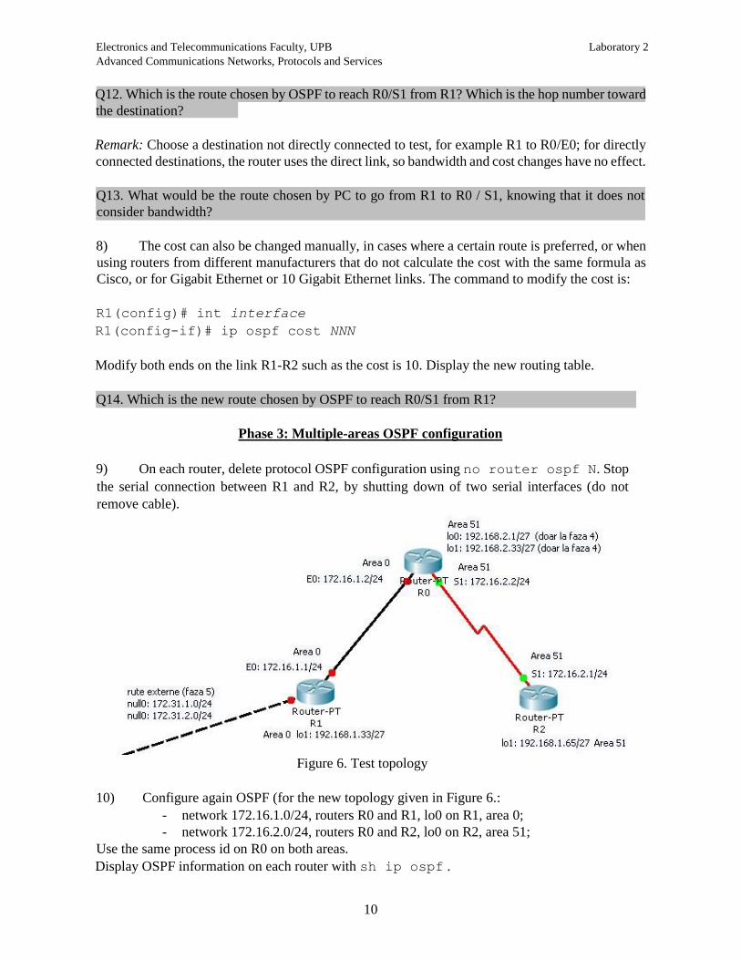
9) On each router, delete protocol OSPF configuration using no router ospf N. Stop
the serial connection between R1 and R2, by shutting down of two serial interfaces (do not
remove cable).
Figure 6. Test topology
10) Configure again OSPF (for the new topology given in Figure 6.:
- network 172.16.1.0/24, routers R0 and R1, lo0 on R1, area 0;
- network 172.16.2.0/24, routers R0 and R2, lo0 on R2, area 51;
Use the same process id on R0 on both areas.
Display OSPF information on each router with sh ip ospf .

Electronics and Telecommunications Faculty, UPB Laboratory 2 Advanced Communications Networks, Protocols and Services
11
Q15. What role has each router?
Q16. Display routing table on each router; which are the prefixes for the routes learned by OSPF?
Q17. In R0, which are the masks for the routes towards the two loopback interfaces?
OSPF announce the routes towards loopback interfaces as “host route” not as “network route”.
Remark the mask used for a host.
Start OSPF debugging on R1 with debug ip ospf events command.
Q18. To which routers and areas do the routing messages belong?
Stop debugging using undebug all command.
Phase 4: Inter-area summarization
11) On R0 configure two loopback interfaces lo0 şi lo1 belonging to 192.168.2.0/27 and
192.168.2.32/27. Configure these networks on OSPF process running on R0 in area 51.
Check with ping if the loopback interfaces are accessible from R1 and R2.
Q19. Check the existence of the two networks in R1’s routing table.
Configure on R0 inter-area summarization (to distribute the two networks from area 51 towards
area0). Use the commands:
R0(config)# router ospf 1
R0(config-router)#area 51 range address mask
Remark! For the mask field use the netmask format not wildcard mask!
Q20. Write the exact address and mask used for the loopback networks. Q21. Display the routing tables on R0 and R1 and write the differences to the previous case. Remark: On R0 the summary type route appears to be connected to the Null0 interface, which does not exist. This is a virtual interface used by the router to bind together the two loopback interfaces, lo0 and lo1.
Phase 5: External router redistribution and summarization
12) First, let’s assume that on R1 (see Figure 6) there is a route to the external network
172.31.1.0. As we don’t have an interface that attach, we use a virtual interface Null0 and we define
a static route to outside through the interface:
R1(config)# ip route 172.31.1.0 255.255.255.0 Null0
Q22. Check the prefix for that route in R1’s routing table.
Electronics and Telecommunications Faculty, UPB Laboratory 2 Advanced Communications Networks, Protocols and Services
12
Let’s import the static route in OSPF:
R1(config)# router ospf 1
R1(config-router)# redistribute static subnets
Remark: without keyword subnets, router will display a message like:
R1(config-router)# redistribute static
% Only classful networks will be redistributed
This is because our route does not correspond to its class.
.
13) Suppose now we add other external routes on R1. Let’s use the same interface:
R1(config)# ip route 172.31.2.0 255.255.255.0 Null0
Q26. Do both routes appear in the routing tables on R0 and R1? Which is the prefix?
Since by continuing this process we get unnecessarily growth of the routing table "exported" by
OSPF, we make an external ASBR summarization:
R1(config)# router ospf 1
R1(config-router)# summary-address adresă mască
Q26. Write the address and mask used?
Q27. Write the changes in the routing tables on R0 and R2? How many routes do we
have now?
Phase 6: Extended ACLs
14) Write and test extended ACLs that prohibit the following types of traffic, and specify the
router and interface where they are placed. Remark! all other traffic must be allowed!
Apply restrictions and test one by one. For testing, may need extended ping and/ or to specify the
source address of the telnet. Before testing the next ACL, delete (or overwrite) the current ACL. In
order not to unnecessarily complicate the exercise, choose one destination address when deny
entrance into a router (which could contain 2-3 interfaces).
Q29. Deny ping from R1/lo1 towards R0.
Q30. Deny telnet from R2 towards R1.
Q31. Deny telnet from R1/lo1 to all other routers.
Q32. Deny telnet from R1 to R2, but allow it in the opposite direction.
Q33. Deny ping from even addresses from network 172.16.1.0/24 to R2
Q24. Check with show ip ospf the role of R1 after redistribution.
Q25. Display the routing tables on R0 and R2 and rite the prefix for the redistributed route.