Embed Size (px)
Citation preview

Facultatea de Electronică şi Telecomunicaţii Advanced Communications Protocols and Services Laboratory 1
1
Laboratory 1 Static routing; dynamic routing with RIP; introduction to ACL
Part1. Theoretical Introduction
1. Static routing
Routers forward packets using either route information from route table entries that are manually configure or the route information that is calculated using dynamic routing algorithms.
Static routes, which define explicit paths between two routers, cannot be automatically
updated; they must be manually reconfigured when network changes occur. Static routes use less
bandwidth than dynamic routes.
A) Setting up a static route is done using one of the following:
Router(config)#ip route destination_network network_mask ip_next_hop
Router(config)#ip route destination_network network_mask output_intf
Obviously, ip_next_hop is a destination known router (located in a directly connected network)! The second variant is only for point-to-point networks, such as those corresponding to serial
interfaces.
For example, to configure a static route on the router to reach the network 192.168.1.0/24:
Figura 1
one will use one of the commands:
Router0(config)#ip route 192.168.1.0 255.255.255.0 172.16.1.2
where 172.16.1.2 is IP address of s2/0 on Router1, or:
Router0(config)#ip route 192.168.1.0 255.255.255.0 s2/0
where s2/0 is the interface of Router0.
B) Default route configuration
For all destinations that do not appear in the routing table one can define a default route:
Router2(config)# ip route 0.0.0.0 0.0.0.0 ip_next_hop|interf_out
For default route 0.0.0.0 0.0.0.0 notation is used because the routing process works as follows:
on compare the destination address with each entry in the routing table using the function AND. The
comparison that fit most bits (longest prefix match) will give the result and it will be your chosen

Facultatea de Electronică şi Telecomunicaţii Advanced Communications Protocols and Services Laboratory 1
2
path. The result of the AND function between a certain address and any other address is in the worst case, 0.0.0.0 (when no bit does not fit). So 0.0.0.0 means "anything".
2. Dynamic routing using RIP
2.1 Introduction
Static routing has the advantage that it is simple, requires no computing power in router for
determining routes (this work is done by the administrator) and does not generate network traffic
(routers do not change the routing information among them), but has the following disadvantages:
• In case of changes, management is difficult; • Do not adjust automatically in case of malfunction; a route that became inaccessible
remains inaccessible until the administrator intervention.
Dynamic routing protocols – shortly called routing protocols- are classified according the
algorithm determining the routing information in: link state protocols and distance vector protocols.
A further classification, which considers the coverage of the routing protocols, divide them in:
• internal routing protocols (IGP - Interior Gateway Protocols), which operated inside a
routing domain consisting of a number routers under a single administration and defining
a so-called autonomous system (AS - Autonomous System
• external routing protocols (EGP - Exterior Gateway Protocols) used to interconnect autonomous systems.
Whatever routing method is chosen, IP routing is of "next hop" type, meaning that each node
only specify the next hop node, as opposed to "source routing" stating the entire way forward between
source and destination. Source routing is not used in the Internet because it requires knowledge of the
entire network centrally and could not easily adapt to unforeseen changes.
2.2 Distance Vector protocols
In distance vector routing protocols the routing information is:
1. determined based on a shortest path algorithm, Bellman-Ford algorithm is the most
significant - the optimal path to destination node is determined considering the cost
determined based on well defined criterias (number of hops/intermediate nodes,
bandwidth of the link between two routers, etc.); 2. distributed to other network nodes to update their routing tables.
Examples: RIP, RIP v2, IGRP, EIGRP, etc. (the last two are Cisco proprietary).
2.3 Link-state routing protocols
In link-state routing protocols routing information is determined:
• through a process of replicating the network topology (replication performed by each
node component of the network) to a database containing information about the status of
the relevant node and the connections adjacent - in this mode each network node gets to
know the positioning of each other node of the network;
• followed by routes calculation - performed by applying an SPF (shortest path first,, "such
as Dijkstra's algorithm) algorithm - a minimum tree routes to each destination.
Example: OSPF.

Facultatea de Electronică şi Telecomunicaţii Advanced Communications Protocols and Services Laboratory 1
3
2.4 Comparative characteristics of routing protocols RIP and OSP
RIP (RFC 1058, 2453, etc.)
• Metric used in path selection is the number of hops;
• Max. 15 hops
• Updates sent by default, every 30 seconds.
-
RIP v2
• updates are sent to the broadcast address 255.255.255.255
• Transmit packets to neighbors and update network mask, to support classless networks
and VLSM (Variable Length Subnet Mask)
• Support authentication
OSPF
• updates are sent to multicast address 224.0.0.9 (addresses with first byte greater than 223
are not in classes A, B, C destinations but have special class called multicast Class D).
• Bandwidth and delay are considered in calculating the optimal path;
• Fast convergence.
-
2.5 RIP protocol configuration
Some commands that allow the study of routing tables and other issues associated routing:
command description
show ip route shows routing table; Networks are classified by
type: those directly connected, the static ones and
learned through routing protocols.
show ip route destination_network Shows information about a route to a specific
destination.
show ip protocols Shows the routing protocols that run on the router.
show ip rip database Shows information about the RIP table.
debug ip rip
removed with
undebug all
Enables debug messages be printed to the
console: each time an event occurs in RIP (eg an
update is sent or received). These messages are
printed to the console only, not via telnet!
Routes learned by the router can be erased with the command:
Router# clear ip route *
where * is a “wildcard” meaning “all routes”. Alternatively, you can specify one route instead of *.
Facultatea de Electronică şi Telecomunicaţii Advanced Communications Protocols and Services Laboratory 1
4
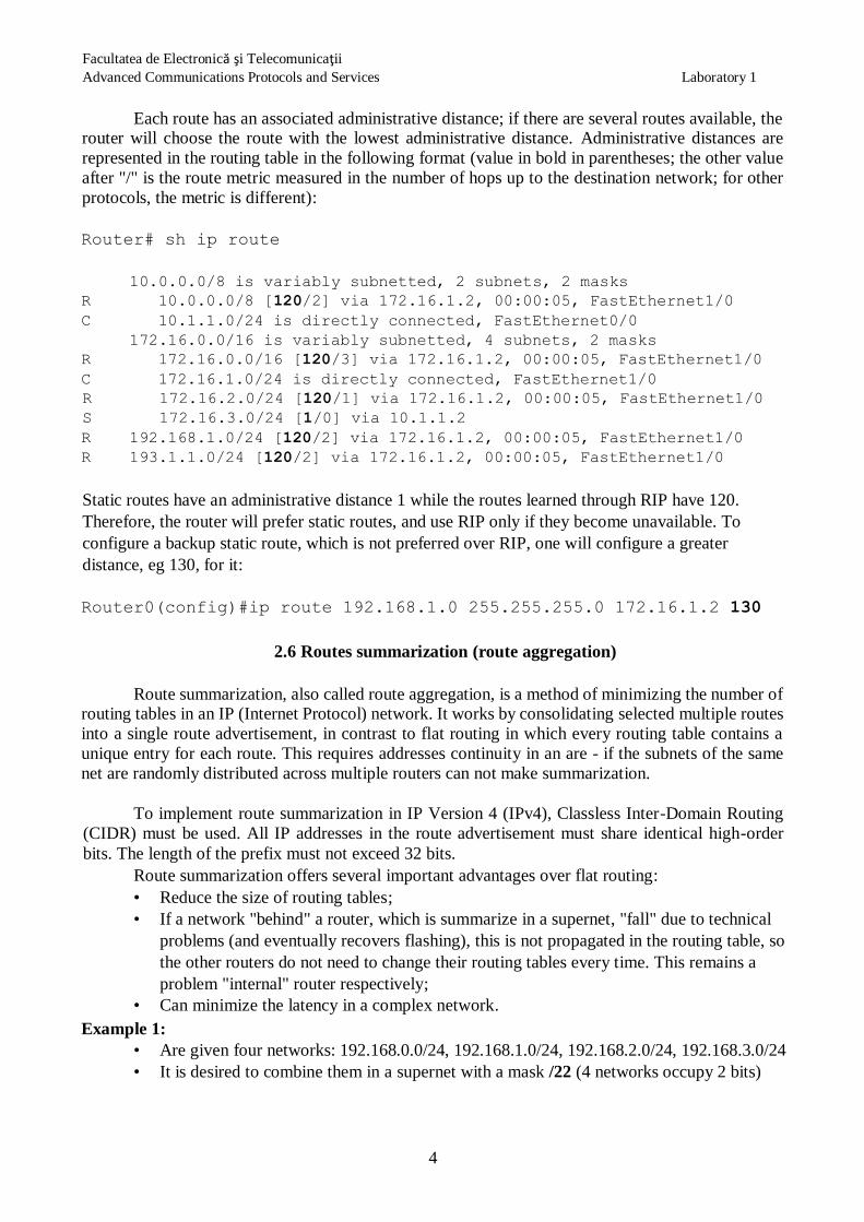
Each route has an associated administrative distance; if there are several routes available, the router will choose the route with the lowest administrative distance. Administrative distances are
represented in the routing table in the following format (value in bold in parentheses; the other value
after "/" is the route metric measured in the number of hops up to the destination network; for other
protocols, the metric is different):
Router# sh ip route
10.0.0.0/8 is variably subnetted, 2 subnets, 2 masks R 10.0.0.0/8 [120/2] via 172.16.1.2, 00:00:05, FastEthernet1/0
C 10.1.1.0/24 is directly connected, FastEthernet0/0 172.16.0.0/16 is variably subnetted, 4 subnets, 2 masks R 172.16.0.0/16 [120/3] via 172.16.1.2, 00:00:05, FastEthernet1/0
C 172.16.1.0/24 is directly connected, FastEthernet1/0 R 172.16.2.0/24 [120/1] via 172.16.1.2, 00:00:05, FastEthernet1/0 S 172.16.3.0/24 [1/0] via 10.1.1.2
R 192.168.1.0/24 [120/2] via 172.16.1.2, 00:00:05, FastEthernet1/0 R 193.1.1.0/24 [120/2] via 172.16.1.2, 00:00:05, FastEthernet1/0
Static routes have an administrative distance 1 while the routes learned through RIP have 120.
Therefore, the router will prefer static routes, and use RIP only if they become unavailable. To
configure a backup static route, which is not preferred over RIP, one will configure a greater
distance, eg 130, for it:
Router0(config)#ip route 192.168.1.0 255.255.255.0 172.16.1.2 130
2.6 Routes summarization (route aggregation)
Route summarization, also called route aggregation, is a method of minimizing the number of routing tables in an IP (Internet Protocol) network. It works by consolidating selected multiple routes
into a single route advertisement, in contrast to flat routing in which every routing table contains a
unique entry for each route. This requires addresses continuity in an are - if the subnets of the same
net are randomly distributed across multiple routers can not make summarization.
To implement route summarization in IP Version 4 (IPv4), Classless Inter-Domain Routing
(CIDR) must be used. All IP addresses in the route advertisement must share identical high-order
bits. The length of the prefix must not exceed 32 bits.
Route summarization offers several important advantages over flat routing:
• Reduce the size of routing tables;
• If a network "behind" a router, which is summarize in a supernet, "fall" due to technical
problems (and eventually recovers flashing), this is not propagated in the routing table, so
the other routers do not need to change their routing tables every time. This remains a
problem "internal" router respectively;
• Can minimize the latency in a complex network.
Example 1:
• Are given four networks: 192.168.0.0/24, 192.168.1.0/24, 192.168.2.0/24, 192.168.3.0/24
• It is desired to combine them in a supernet with a mask /22 (4 networks occupy 2 bits)

Facultatea de Electronică şi Telecomunicaţii Advanced Communications Protocols and Services Laboratory 1
5
• Supernet written in binary (bold) will be 192.168.00000000.00000000 ie 192.168.0.0/22 -
so four independent network of 256 addresses can be written as a supernet with 1024
addresses.
•
Example 2:
10.10.1.0/24 networks, 10.10.2.0/24 ..., 10.10.255.0/24 are perceived as the “bigger” network
10.10.0.0/16. Supernet 10.10.0.0/16 was obtained by performing the operation "AND" logic between
the four bytes of the initial network. Notice that it is not a typical supernet - the class limit is /8.
3. Access Control Lists - ACL
3.1 Introduction
An ACL allows the establishment of rules to be allowed or denied the access for packages with
specific IP addresses, either entirely or only to certain destinations, ports or protocols. Practically,
using ACL one could build a firewall using a Cisco router. Examples of rules:
• 192.168.1.1-192.168.1.63 hosts will not have access to the web sites from a list;
• Students’ computers will only have access to certain websites; • No host outside the domain will have Telnet access to local hosts within the domain, but
the converse will be allowed
Specifying the hosts affected by the rule is done with the pair ip_address, wildcard_mask.
3.2. Wildcard masks in ACL
A wildcard mask shows similarities with a netmask, meaning that it allows to specify to
which bits of the IP address a rule applys. Specifically, select / check those bits of the IP address that
have "0" in the mask and ignore those who have "1" in the mask, somewhat opposite to the netmask.
But wildcard masks are more general and are not necessarily equal to the inverse netmask.
The case where they are equal is when one needs to specify an entire network or subnet, e.g.,
to bann or allow traffic from all hosts on a network. For example, to specify "whole network
192.168.1.0/24" is written: 192.168.1.0 0.0.0.255, i.e. check (0 = check) the first 3 bytes
in the IP address of the incoming packets to match 192.168.1.x. Check that no host bits rule is
equivalent to saying that the rule applies to all hosts on the net.
Cases where they are not equal appear to be achieved when more complex selections, ie only
part of the hosts on a network. This means that a wildcard mask enables you to select specific hosts
without having to create subnets only for this.
For example, let’s consider the network 192.168.1.0/24, which is not subnetted. We’ll assign the
hosts with large numbers (from 193 up, which would be equivalent to the last subnet length / 26) for
the management team and hosts 1-192 to employees. In terms of routing, all hosts must access the
Internet, so it makes no sense to subnettize the network, but we want to give access to an intranet
Web site only to the management. This is specified with the syntax:
• IP address 192.168.1.11000000 and wildcard mask 0.0.0.00111111
meaning: 192.168.1.192 0.0.0.63 in decimal format.
So, ACL will check the hosts to start with 11 in binary, even if the network mask remains
255.255.255.0 (netmask does not appear in the ACL). Moreover, we could add another rule, dividing
further the hosts greater than 192 as follows: first for "lower management" and the last for "upper

Facultatea de Electronică şi Telecomunicaţii Advanced Communications Protocols and Services Laboratory 1
6
management", differentiating still ACLs additional restrictions (not all have the same access, or the same speed, etc.).
Each rule can have its own wildcard mask. We can create a completely different rule, which
runs in parallel with the first. For example, if odd hosts are to be placed on the 1st floor and even
numbered hosts on the 2nd floor of the building (odd / even binary means that ends in binary 0 or 1). This way, if you want to give access only to those with odd hosts to the printer on the 1st floor, specify
the hosts with a combination of:
address 192.168.1.11111111 wildcard mask 0.0.0.11111110 means:
192.168.1.255 0.0.0.254 in decimal.
note that in the position where we have "1" in the wildcard mask the IP address bits does not matter, ACL will check only the last bit of the host! (We could write as well 192.168.0.1 or 192.168.0.3
address or anything that ends with "1" in binary!)
In conclusion, netmask remains unique routing process, while using different masks in
different wildcard rules, we can fine tunning traffic access to/from certain network hosts.
Some widely used expression have a short form equivalent:
expression (IP_address, mask) Short form explanation
A.B.C.D 0.0.0.0 host A.B.C.D because 0.0.0.0 means “check all
bits”, the address will point to a
single host.
0.0.0.0 255.255.255.255 any because 255.255.255.255 means
“ignore all bits”, all the addresses are
refered.
3.3 ACL Configuration
There are two tipse of ACL for Cisco routers:
• Standard ACLs have numbers between 1-99 and they allow specifying the source address
of the IP packet only. Therefore, they must be placed in the network closer to the destination ACL, because the packets can reach the destination on multiple paths.
Configuration commands:
Router(config)# access-list number deny|permit [remark] adr_source
wildcard_mask [log]
Deny option is used to block the packets with adr_source IP address and permit option will allow the packet. Remark option allows writing a comment on the list; log option generates a recording in
the router log file when an event triggers the application ACL's.
Example:
access-list 1 deny host 192.168.1.1
block all the packets coming from the specified host.
access-list 2 permit 192.168.1.0 0.0.0.255

Facultatea de Electronică şi Telecomunicaţii Advanced Communications Protocols and Services Laboratory 1
7
allows the traffic from all the hosts in network 192.168.1.0/24.
• Extended ACLs have numbers between 100-199 or 2000-2699. They allow to specify
source address, destination address, protocol and port which makes them more
versatile.
Simply defining an ACL as described above has no effect on the router. Further, it should be used.
The simplest situation is when the ACL is placed on a router interface. It uses command (in interface
configuration mode is desired):
Router(config-if)# ip access-group număr_ACL in|out
where the entry (in) or output (out) is considered looking from "inside the router". For example, the placement of ACL number 1 on the interface S0/1 so as to affect the packets entering the router via
the interface (whose IP address was previously configured):
Router(config)# int S0/1
Router(config-if)# ip access-group 1 in
Router(config-if)# CTRL-Z
Using the prefix "no"the ACL can be removed from interface (e.g., no ip access-group ...);
thus, it will be disabled without having to delete ACL's. Also, one can use "no" to completely delete
an ACL: no access-list 101 ... .
3.4 Remarks about ACL
1. On an interface and a sense apply only one ACL (defined by access-group number), but can
have multiple ACL rules. For example, to declare an ACL with two rules:
access-list 10 permit host 192.168.1.1
access-list 10 deny host 192.168.1.2
2. Each new rule is added after the existing ones. They will be checked in the same order they
have been declared. For ACL, the prefix "no" delete all rules (you can not selectively delete
or modify rules).
3. It is important to understand that when the router receives a packet on an interface, it checks
the rules on that packet in the order they were defined and performs first permit or deny action
type that matches that packet, after which the check stops. Result: the order is essential when
the rules in an ACL are defined.
For example, suppose we want to allow traffic from 192.168.1.1 but to prohibit traffic from other hosts of 192.168.1.0. The following definition is correct:
access-list 1 permit host 192.168.1.1
access-list 1 deny 192.168.1.0 0.0.0.255
but the next approach is wrong:

Facultatea de Electronică şi Telecomunicaţii Advanced Communications Protocols and Services Laboratory 1
8
access-list 1 deny 192.168.1.0 0.0.0.255
access-list 1 permit host 192.168.1.1
because the package 192.168.1.1has already been rejected by the first rule, deny 192.168.1.0,
which is more general (192.168.1.1 belongs to 192.168.1.0/24 network), then it stops checking the
other rules. It follows that we must define in order, less general rules first and then more general rules.
4. If the router does not specify any ACL, by default all traffic is allowed. But if an ACL is defined, all traffic not specified by that ACL is implicitly prohibited. Therefore, if on a router
N rules are defined, there exist an implicit N + 1-rule deny any, that denys everything else.
Therefore, if desired permissive default behavior, everything that was not specified in the ACL must
be allowed by adding allow any rule at the end.
Attention! in the absence of permit any rule, we may block including routing updates and the
router could stop work.
3.5 Testing ACLs
To test the ACL operation, traffic type specified in ACL must be generated and check whether the
router behavior is correct.
Figur2 2
For example, in Figure 2, we assume that we have created an ACL on R1 to prevent traffic from
addresses 192.168.1.0/24 to 172.16.2.1/24. If we connect the R0 and give the command "ping
172.16.2.1" we find that the source address is 192.168.1.1 IP packets, but 172.16.1.1, as both are valid addresses of R0, and the second address is near the destination. Therefore, you must manually select
the source interface to ping and telnet packets.
• To force packages of "ping" to have a certain source address the extended ping, ping
ie no parameters. Then the router will ask for desired protocol, source address, number of
packages, etc. The default answer to each question is displayed in square brackets. Note that at the "extended commands" must answer yes(y).
• For using Telnet instead of ping packets one can force "telnet" to leave the router with a
certain source address using the command:
ip telnet source-interface adresa_ip
• Attention! A router ACLs do not check local traffic on the router. It checks traffic from
other devices connected to that router.
Facultatea de Electronică şi Telecomunicaţii Advanced Communications Protocols and Services Laboratory 1
9
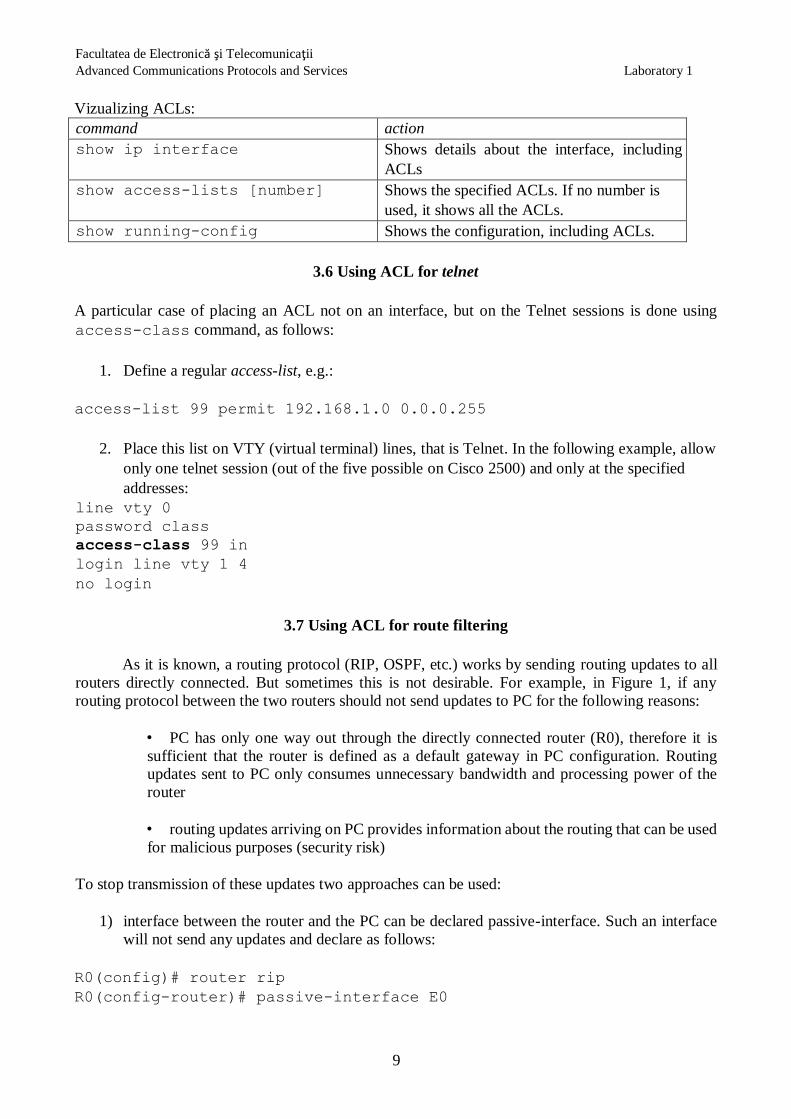
Vizualizing ACLs:
command action
show ip interface Shows details about the interface, including
ACLs
show access-lists [number] Shows the specified ACLs. If no number is
used, it shows all the ACLs.
show running-config Shows the configuration, including ACLs.
3.6 Using ACL for telnet
A particular case of placing an ACL not on an interface, but on the Telnet sessions is done using
access-class command, as follows:
1. Define a regular access-list, e.g.:
access-list 99 permit 192.168.1.0 0.0.0.255
2. Place this list on VTY (virtual terminal) lines, that is Telnet. In the following example, allow
only one telnet session (out of the five possible on Cisco 2500) and only at the specified
addresses:
line vty 0
password class
access-class 99 in
login line vty 1 4
no login
3.7 Using ACL for route filtering
As it is known, a routing protocol (RIP, OSPF, etc.) works by sending routing updates to all
routers directly connected. But sometimes this is not desirable. For example, in Figure 1, if any
routing protocol between the two routers should not send updates to PC for the following reasons:
• PC has only one way out through the directly connected router (R0), therefore it is
sufficient that the router is defined as a default gateway in PC configuration. Routing updates sent to PC only consumes unnecessary bandwidth and processing power of the
router
• routing updates arriving on PC provides information about the routing that can be used
for malicious purposes (security risk)
To stop transmission of these updates two approaches can be used:
1) interface between the router and the PC can be declared passive-interface. Such an interface
will not send any updates and declare as follows:
R0(config)# router rip
R0(config-router)# passive-interface E0

Facultatea de Electronică şi Telecomunicaţii Advanced Communications Protocols and Services Laboratory 1
10
2) a more versatile method involves the use of the ACL to specify which networks will be
allowed and which will be prohibited in routing updates. This way you can control very
precisely routing; for example, a border router (at the network edge) will not send updates
about local networks to the outside, to reduce routing table size or from security reasons.
De exemplu, în figura 1, reţeaua 192.168.1.0 dintre ruter şi PC trebuie ascunsă în updates trimise de
R1 în exterior; se defineşte un ACL care să interzică doar acea reţea:
R1(config)# access-list 50 deny 192.168.1.0 0.0.0.255
R1(config)# access-list 50 permit any
Apply the ACL using keyword distribute-list, which act as a filter:
R1(config)# router rip
R1(config-router)# distribute-list 50 out
Remarks:
• filter can be applied in other routing protocols, not just RIP
• Key word out means that these networks will not be sent in updates. It is possible to
specify using the key word in not to allow receiving updates about certain networks;
• In this example, placing the filter prohibits sending updates on all interfaces, which
does not affect the operation of routing in PC-R0-R1 (R1 learned from this network from
R0, so anyway will not return). In some cases, however, the restriction can be applied
only on an interface, adding the key word interface:
R1(config-router)# distribute-list 50 out interface S0/1
Or with simplified sintax:
R1(config-router)# distribute-list 50 out S0/1
Part 2. Practical exercises
Faze 1. Pregătirea topologiei de test; rutare statică
1) Implement in GNS3 the topology given in Figure 3, configuring on each router:
- hostname
- IP addresses
- loopback interfaces caled lo1
- clockrate (64000) for DCE serial interfaces
- no shutdown on interfaces
- telnet password will be class.

Facultatea de Electronică şi Telecomunicaţii Advanced Communications Protocols and Services Laboratory 1
11
Figura 3
Check with ping command the connectivity between nodes.
On R0 define a static route towards R1/S1.
ip route 172.17.1.0 255.255.255.0 172.16.1.2
Try to ping 172.17.1.1 from R0.
Q1: Does ping work?
Q2: Install a static route on R1 to be able to ping R0/S0; Write the command. Test it with ping..
By default ping requires to specify only the destination address. We can check, for example if ping
works from R1/Lo1 on R0 / E0. To specify the source address ping and not just the destination,
extended ping should be used; for example, on R 1:
R1# ping Protocol
[ip]:
Target IP Address: 172.16.1.1
Repeat count [5]:
Datagram size [100]:
Timeout în seconds [2]:
Extended commands [no]: y
Source address or interface: 192.168.1.65
Type of service [0]:
Set DF bit în IP header [no]:
Data pattern [0xABCD]:
Loose, strict, record, timestamp, verbose [None]:
Sweep range of sizes [n]:
Type escape sequence to abort.
Sending 5, 100-byte ICMP Echos to 172.16.2.1, timeout is 2 seconds:
!!!!!
Success rate is 100 percent (5/5)

Facultatea de Electronică şi Telecomunicaţii Advanced Communications Protocols and Services Laboratory 1
12
Q3: Does ping work? Why?
Note that for ping (and in general, routing IP) to work, it is not enough to known path from A to B, if
it is not known path from B to A.
To vizualiza the routing table use show ip route.
Q4: Vizualize the routing table on R0; what networks does R0 know? Specify the difference between
the routes labeled with S and those labeled with C.
Q5: Add a static route on R0 to lo1 network on R1. Write the command. Repeat the test with extended
ping. Does it work now? Why?
Faze 2. Install default routes
In this scenario, it is desirable that R0 to have access to the redundant network 172.17.1.0, either
through R1 or R2. It is a similar situation with a client who has access to the internet via two ISPs,
one basic and one backup. The preferred route will be via R1 and R2 will be the backup route.
R0 already knows a route to 172.17.1.0; clear the route using prefix no:
no ip route 172.17.1.0 255.255.255.0 172.16.1.2
Check with show ip route on R0 that route disappeared from the routing table.
Configure two static routes default type, with different administrative distances (130 and 140).
Remember that Cisco routers will prefer smaller administrative distances (0 = best route 255 = route
that will never be used). Configure on router R0:
ip route 0.0.0.0 0.0.0.0 172.16.1.2 130 ip
route 0.0.0.0 0.0.0.0 10.1.1.2 140
Q6: What does the 0.0.0.0 0.0.0.0 expression represent?
Test the connection with ping towards any of the interfaces R1/S1 sau R2/S1. Check the routing table
on R0 with show ip route.
Q7. Who is mentioned in R0’s routing table as “gateway of last resort” ?
Q8. In the table the network 172.17.1.0/24 is not mentioned. Why does the ping work? How does R0
know to reach the network?
The left link is interrupted when shutdown interface E0 of R0; Check the new routing table and that
the ping to 172.17.1.2 still works.
Q9. Who is mentioned now in R0’s routing table as “gateway of last resort” ?
Restart the shutdown interface (no shutdown on interface E0).

Facultatea de Electronică şi Telecomunicaţii Advanced Communications Protocols and Services Laboratory 1
13
Faze 3. RIP configuration
Install a classful routing protocol - RIP Version 1 (by default, unless specified version is v1).
To have a "clean" topology all the static routes that have been defined so far are deleted by prefixing
with "no":
Router(config)# no ip route ...
Router(config)# no ip route ...
Router(config)# exit
Delete the routing table:
Router# clear ip route *
To configure RIP, there should be listed with the key word network all networks directly connected
to the router (including loopback and PCs networks), by specifying only the address of the network,
not the network mask.
Router(config)# router rip
Router(config-router)# network ... Router(config-router)#
network ...
Q10. Write the RIP configuration for each router ?
Check the routing table with sh ip route; check RIP functioning with sh ip protocols.
Q11. What label is used for RIP learned routes in the routing table?
Q12. On R0, does the routing table contains the networks 192.168.1.64/26 şi 192.168.1.128/26? If
not, how they are reffered in the routing table?
Q13. Using sh running-config check on router R1 the configuration line network for
192.168.1.64. What does it hapened?
Ping between any two network nodes. Note that it does not work in all cases, which means that RIP
is not configured correctly.
Q14. Does ping work from R1 to 192.168.1.129? Why?
In this case, using a classful protocol, the routes are summarized, meaning that RIP combines all
routes to subnets into a single route to the corresponding net. For example, the route to 192.168.1.64/26 is replaced by 192.168.1.0/24. This is a major problem in the case where there are
two subnets of the same net, such as the two subnets represented by LO1 on R1 and R2, and the
subnets are non-contingue (in this case, are separated by two other networks attached to R0).
Visualize sending routing updates on R1 with the debug ip rip command.
Q15. What networks does R1 send in update messages? Are the subnets correct? Towards which
address the routing table is sent (messages sending v1 update via...)?

Facultatea de Electronică şi Telecomunicaţii Advanced Communications Protocols and Services Laboratory 1
14
Stop debugging with the command undebug all.
If the two subnets were both attached to R1, there would be no problem. Because through
summarization R1would announce that it knows a route to 192.168.1.0/24, any package by .33 or .65
that would reach the R1, would be distributed by R1 to the correct subnet. In this case, summarizing
would be an advantage, because instead transmit updates about two routes R1 would provide updates
about one route, reducing routing table size sent to the neighbors. Without summarization, the Internet
today could not function, the routing tables would become huge. For non-contigue subnets
summarization provides false information that the two subnets are available simultaneously on R1 and
R2.
Changing the RIP version from 1 to 2 (v1 to v2) will solve this issue. It is possible to simply add
lines "version 2" and "no auto-summary" in router rip configuration mode; But sometimes
problems could occur in operation, so the safest way is to first stop RIP v1 protocol on each router:
Router(config)# no router rip
Router(config)# CTRL-Z
Configure RIP v2 similarly with RIP v1 configuration, but add some extra lines:
Router(config)# router rip
Router(config-router)# version 2
Router(config-router)# no auto-summary Router(config-router)#
network ....
Note no auto-summary additional command. This is not related to the difference between v1 and
v2 (Internet routers use summarization ), but obviously we do not want this topology summarizing,
because of non-contingue subnets.
Analyze router configuration with sh running-config. Note that, although we have requested
no summarization, all routes are shown summarized in the class imit; this is a restriction of RIP: even
if the routing table displays them correctly, the show running-config behavior is unchanged.
Vizualize the routing table on R1 with sh ip route.
Q16. Which line on the screen shows the effect of no auto-summary command?
Check that all destinations are reacheable from R1. Vizualize the routing updates
messages using debug ip rip.
Q17. Write the routes sent by R1 in routing updates noticing if the subnets masks are correct. Which
is the significance of metric parameter reported by each network? Towards which address does R1
send the routing table (check with sending v2 update via ....).
Although, after learning, each router knows the routes to all networks, the router R2 does not send
notice to R0 networks received from the latter, but only their networks.
Q18. Which is the reason of such behavior?

Facultatea de Electronică şi Telecomunicaţii Advanced Communications Protocols and Services Laboratory 1
15
Q19. For R1, does RIP send updates on all interfaces? Are all these updates necessary?
Which are not necessary?
Stop debugging with undebug all.
Q20. Check the connectivity between the two PCs with ping. Does it work? Why?
Stop sending routing updates on those interfaces which are not connected to other routers:
Router(config)# router rip
Router(config-router)# passive-interface nume_interfaţă
Check with debug ip rip that updates are not sent on the interface anymore. Stop debugging.
Faze 4. Emulating an Internet link with loopback
We will simulate the Internet with a new loopback interface lo2 connected to R2. Configure this
interface with address 172.30.1.1/24.
Configure the network on this interface as default, i.e., the network where all packets are sent for
which no explicit destination exists:
R2(config)#ip default-network 172.30.1.0
Q21. Check on R0 if it can reach 172.30.1.1. Does it work? Why?
Q22. Examine the routing table on R0 with show ip route. There is a gateway of last
resort (equivalent with default gateway in Windows/Linux)?
Configure R2 to distribute the default route towards the other routers:
R2(config)# router rip
R2(config-router)# default-information originate
Q23. Waite route information propagation among routers. Which are the two lines shown by sh ip
route on R0, which contain information about default route and default router? (gateway of last
resort). Which symbol is shown as prefix for the default route in the routing table?
Q24. Try to ping “Internet”(172.30.1.1) from R1. Does it work? Why?
Q25. Which of the three routers has gateway of last resort set? Explain the result.
Faze 5. Routes redistribution
In order RIP to announce a route, it is not necessarily that it be a path defined by "network" in its
configuration, or default route. Generally, RIP may announce and other types of routes l to its

Facultatea de Electronică şi Telecomunicaţii Advanced Communications Protocols and Services Laboratory 1
16
neighbors. RIP distribution of routes that it learned from another source (and not by direct
configuration) is called redistribution.
Define a static route on R:
R2(config)# ip route 192.168.100.0 255.255.255.0 null0
Null0 interface does not exist and therefore the route will not work, but we've created it just to see
that RIP will propagate it. Train RIP to redistribute static routes:
R2(config)# router rip
R2(config-router)# redistribute static
Check the routing table on R1 and R0.
Q26: Which is the new record in the rpouting table?
Faze 6. ACL configuration
To remove ambiguity between the two destinations (PCs), for easier configuration of ACL, we will eliminate direct link between routers that are connected to the 2 PCs (serial link between R1 and R2
in Figure 3).
Follow routing table updates of R1 and R2 (after convergence). Verify that it is still possible pinging
between different destinations that are not directly connected. Ping is important to go now in tsting ACLs, because if it does not work we need to be sure it's because of the ACL, not from a faulty
configuration.
Q27. Define and apply an ACL, which will not allow traffic from PC9x to R2, the rest being allowed. Explain how you did. Test with ping
Q28. Define and apply an ACL, that will not allow the traffic from R2/lo1 to R0, the rest being
allowed. Explain how you did. Test with ping. What kind of ping should be used?
Q29. Using an ACL placed on Telnet (with access-class), only allow Telnet to R2 from R1/lo1.
Explain how you did. Test with telnet. What command must be prior issued on R1 before testing?