Embed Size (px)
Citation preview

http://www.mf.unze.ba/Masinstvo
Godina (Volume) 15 Broj (Number) 1, Januar- Mart (January - March) 2018.
LABORATORIJ ZA NEMETALNE MATERIJALE
Ispitivanje kamena i kamenog agregata: čvrstoća na pritisak,zatezanje i savijanje, otpornost na abraziju, granulometrijskisastav, zapreminska i specifična masa...
konzistencija,Ispitivanje betona i betonskih elemenata:sadržaj zraka, čvrstoća na pritisak, čvrstoća na zatezanje prisavijanju i cijepanju, ultrazvučna ispitivanja, otpornost na mraz,izrada receptura za beton, itd.
ekstrakcija bitumena iz mješavine;Ispitivanje asfalta:zapreminska masa; Marshallov test...
DSC, DTA, TGA, dilatometrija, vatrostalnost,Ispitivanje gline:granulometrijski sastav, ponašanje pri sušenju i pečenju...Pored navednih materijala u Laboratoriju se ispituju svojstvavezivnih sredstava (cement, kreč, gips), nusprodukti industrijskihprocesa (šljaka, pepeo), drvo, opekarski proizvodi itd.
Adresa: Travnička cesta 1, 72 000 ZenicaTelefon: +387 32 401 831E-mail: [email protected]: www.mtf.unze.ba
UNIVERZITET U ZENICIMetalurško-tehnološki fakultet

1
ISSN 1512-5173 http://www.mf.unze.ba/masinstvo
MAŠINSTVO ČASOPIS ZA MAŠINSKO INŽENJERSTVO
JOURNAL OF MECHANICAL ENGINEERING Godina (Volume) 15, Broj (Number) 1, Zenica, Januar – Mart (January – March) 2018.
Uredništvo (Editorial): Fakultetska 1, 72000 Zenica Bosnia and Herzegovina Tel: +387 32 449 143; 449 145 Fax: +387 32 246 612 e-mail: [email protected] [email protected] [email protected]
Osnivač i izvršni izdavač (Founders and Executive Publisher): University of Zenica Faculty of Mechanical Engineering Fakultetska 1, 72000 Zenica Bosnia and Herzegovina Recenzioni odbor (Review committe): Dr. Aleksandar Karač, Dr. Mustafa Imamović, Dr. Safet Brdarević, Dr. Nermina Zaimović-Uzunović, Dr. Samir Lemeš
Glavni i odgovorni urednik (Editor and Chief): Prof. Dr. Sc. Safet Brdarević
Časopis izlazi tromjesečno (The journal is published quarterly)
Urednički odbor (Editorial Board): Dr. Safet Brdarević (B&H), Dr. Jože Duhovnik (Slovenia), Dr. Vidosav Majstorović (Serbia), Dr. Milan Jurković (Croatia), Dr. Sabahudin Ekinović (B&H), Dr. Gheorge I. Gheorge (Romania), Dr. Alojz Ivanković (Ireland), Dr. Joan Vivancos (Spain), Dr. Ivo Čala (Croatia), Dr. Slavko Arsovski (Serbia), Dr. Albert Weckenman (Germany), Dr. Ibrahim Pašić (France), Dr. Zdravko Krivokapić (Montenegro), Dr. Rainer Lotzien (Germany)
Tehnički urednik (Technical Editor): Prof. Dr. Sabahudin Jašarević Štampa (Print): Štamparija Fojnica d.o.o., Fojnica Uređenje zaključeno (Preparation ended): 31.03.2018.
Časopis je evidentiran u evidenciji javnih glasila pri Ministarstvu nauke, obrazovanja, kulture i sport Federacije Bosne i Hercegovine pod brojem 651. Časopis u pretežnom iznosu finansira osnivač i izdavač. Časopis MAŠINSTVO u pravilu izlazi u četiri broja godišnje. Rukopisi se ne vraćaju
The Journal is listed under No 651 in the list of public journals in the Ministry of science, education, culture and sport of the Federation of Bosnia and Herzegovina. The Journals is mostly financed by founder and publisher. Frequency of Journal MAŠINSTVO is 4 issues a year. Manuscripts are not returned
Časopis objavljuje naučne i stručne radove i informacije od interesa za stručnu i privrednu javnost iz oblasti mašinstva i srodnih grana vezanih za područje primjene i izučavanja mašinstva. Posebno se obrađuju slijedeće tematike: - tehnologija prerade metala, plastike i gume, - projektovanje i konstruisanje mašina i postrojenja, - projektovanje proizvodnih sistema, - energija, - održavanje sredstava za rad, - kvalitet, efikasnost sistema i upravljanje proizvodnim i poslovnim sistemima, - informacije o novim knjigama, - informacije o naučnim skupovima - informacije sa Univerziteta,
The journal publishes scientific and professional papers and information of interest to professional and economic releases in mechanical engineering and related fields. In particular, the following topics are treated: - Technology for processing metal, plastic and rubber, - Design and construction of machines and plants, - The design of production systems, - Energy, - Maintenance funds for the work, - Quality and efficiency of the system and the management of production and business systems, - Information about new books, - Information about scientific meetings - Information from the University,
2
RIJEČ UREDNIKA Poštovane kolegice i kolege Ovim 57-im brojem Časopisa ulazimo u 15 godinu aktivnog izlaženja. Prvi broj Časopisa je zapravo izišao u prvom kvartalu 1996 godine, dakle prije 23 godine. Zbog problema izdavača nastao je prekid u izlaženju od 7 godina. Uredništvo Časopisa u svom izdavačkom programu uvrštava širok dijapazon naučno-istraživačkih i stručnih radova iz oblasti tehničkih nauka te svih ostalih nauka koje su u svrsi savremenih tehnologija. Do sada je objavljeno blizu 300 naučnih i stručnih radova iz cijelog svijeta. Kada je u pitanju razvoj nauke i struke uprkos golemim rezultatima u kojima i naš Časopis daje skroman doprinos, uvijek se treba vraćati na problem odnosa spram čovjeka i društva. Dakle, budućnost struke i nauke je u ostvarivanju harmonije između čovjeka, prirode, tehnologije i same nauke. Objavljeni tekstovi kao i oni koji će se objavljivati imaju stručni i naučni doprinos i rezultate koje je moguće primjeniti u razvoju tehnike i osavremenjavanju tehnologija. Moja nada i istovremeno i apel za cjelovitim naučnim pristupom u ostvarenju harmonije čovjeka, nauke i tehnologije. Ovaj broj Časopisa, prvi u 2018 godini, donosi 6 testova autora uglavom iz BiH. U okviru informacija predstavljamo pozive za dva naučna skupa iz oblasti Održavanja (BiH i Hrvatska), a na prvoj strani korica predstavljena je jedna Laboratorija Univerziteta u Zenici te na zadnjoj strani korica predstavljamo uspješno preduzeće iz oblasti drvne industrije. Nadamo se da našim naporima dajemo doprinos razvoju struke i nauke, Vas lično, Vaših preduzeća i ustanova te naše zemlje.
Vaš glavni i odgovorni urednikProf. emeritus dr. Safet Brdarević
EDITORIAL Dear Colleagues With this 57th issue of Journal, we enter into 15 years of active exhibition. The first issue of the Journal was actually in the first quarter of 1996, ie 23 years ago. Due to the publisher's problem, there was an abortion in the 7-year term. The Editorial Board of the Journal incorporates a wide range of scientific research and professional papers from the field of technical sciences and all other sciences that are intended for modern technologies. So far, nearly 300 scientific and professional papers have been published all over the world. When it comes to the development of science and technology, despite the enormous results in which our Journal gives a modest contribution, we must always return to the problem of relations between man and society. So the future of the profession and science is to achieve harmony between man, nature, technology, and science itself. Published texts as well as those to be published will have expert and scientific contributions and results that can be applied in the development of technology and the modernization of technology. My hope is, at the same time, appealing for a complete scientific approach to the achievement of human, science and technology harmony. This issue of the Journal, the first in 2018, brings six paper of the author from BH. Within the information we present calls for two scientific meetings in the field of Maintenance (BiH and Croatia), and on the first page of the chassis is presented one Laboratory of the University of Zenica and on the bottom of the chassis we present a successful company in the field of wood industry. We hope to make our efforts contribute to the development of the profession and science, yourself, your companies and institutions and our country.
Your editor in chiefProf. emeritus dr. Safet Brdarević
SADRŽAJ
1. Numerička simulacija dvofaznog strujanja sa međufaznom površinom Berberović E. 3 2. Eksperimentalna analiza izvijanja plastičnih kontejnera Hodžić D., Hodžić A.; Islamović F. 13 3. Metodologija, alati i mogućnosti strukturne analize kuke u sklopu donje koturače u CAD/CAE sistemu Catia Papić S.; Hasanović E. 21 4. Procedura osnivanja mikro postrojenja obnovljivih izvora energije i isplativost investicije Tiro D. 31 5. Proračun indeksa pouzdanosti na primjeru rama čelične hale, usporedba PTP i EC-1 propisa za opterećenje snijegom Hadžović R.; Redžić V.; Redžić N. 41 6. Istraživanje veze između motivacije studenata inžinjerstva i pristupa integrisane nastave engleskog jezika i struke (CLIL) Tarabar A.; Ahmetspahić A. 49 Uputstvo za autore 57
CONTENTS
1. Numerical Simulation of Two-Phase Interfacial Flows
Berberović E.. 3 2. Experimental Buckling Analysis of Plastic Containers Hodžić D., Hodžić A.; Islamović F. 13 3. Methodolgy, Tools and Possibilities of Structural Analysis of Hook Construction in CAD/CAE System Catia Papić S.; Hasanović E. 21 4. The Procedure of Establishing Micro Plant of Renewable Energy Sources and the Profitability Tiro D. 31 5. Calculation Index of Reliability on the Example of Steel Hall, Comparation of PTP and EC-1 Regulations for Snow Load Hadžović R.; Redžić V.; Redžić N. 41
6. A Research Into a Connection Between Engineering Student Motivation and the CLIL Approach Tarabar A.; Ahmetspahić A. 49 Instruction for authors 57

Mašinstvo 1(15), 3 – 12, (2018) E. Berberović.: NUMERICAL SIMULATION…
3
NUMERIČKA SIMULACIJA DVOFAZNOG STRUJANJA SA MEĐUFAZNOM POVRŠINOM
NUMERICAL SIMULATION OF TWO-PHASE INTERFACIAL FLOWS
Edin Berberović Polytechnic Faculty University of Zenica Ključne riječi: numerička simulacija, dvofazno strujanje, metoda volumena fluida Keywords: numerical simulation, two-phase flow volume-of-fluid method Paper received: xx.xx.xxxx. Paper accepted: xx.xx.xxxx.
Stručni rad REZIME U radu se predstavlja volume-of-fluid (VOF) metod za praćenje međufazne površine u toku sa slobodnom površinom u softveru OpenFOAM®. VOF-model koristi algebarsku kompresivnu shemu za efektno sužavanje tranzicionog područja između tečne i gasovite faze. Podobnosti modela demonstriraju se simulacijom dvodimenzionalnog aksisimetričnog razvoja oblika kapljice u bezgravitacionoj okolini, kao i udara kapljice u tečni film na ravnom zidu. Uvidom u rezultate model daje dobre performanse za proračun dvofaznih tokova.
Professional paper
SUMMARY The paper presents the volume-of-fluid (VOF) method for interface capturing in free surface flows in OpenFOAM® software. The VOF-model utilises an algebraic compressive scheme to effectively shrink the transitional region between the liquid and the gaseous phase. The capabilities of the model are demonstrated by simulating two-dimensional axisymmetric droplet shape evolution in a gravity-free environment, as well as drop impact on a liquid film at the flat wall. By inspection of results the model yields good performance for the computation of free-surface flows.
1. INTRODUCTION Intensive and increased development of computers and computing power and efficiency have led to wider use of numerical methods in computations of free-surface flows. Numerical simulations are used to obtain a detailed insight into the dynamics of such flows with an amount of information which is experimentally and theoretically unachievable. Free-surface flows are important in many applications, such as ink-jet printing, paint spraying, internal combustion engines and spray cooling. These flows are very complex and there is ongoing research in developing models capable of computing them [1,2,3]. In the present paper the algebraic compressive VOF-model for interface capturing in computations of free-surface flows in the open-source CFD software OpenFOAM®[4] is presented. 2. COMPUTATIONAL MODEL The main feature of the VOF-model is the motion of two incompressible immiscible fluids being modelled as a single effective fluid, the physical properties of which are weighted averages between the properties of each of fluids
1. UVOD Intenzivan i ubrzan razvoj računara i računarske snage i efikasnosti doveli su do široke primjene numeričkih metoda u proračunima tokova sa slobodnim površinama. Numeričke simulacije se koriste za dobijanje detaljnog uvida u dinamiku takvih tokova uz ogromnu količinu informacija koje su nedostupne eksperimentalno i teorijski. Tokovi sa slobodnim površinama su važni u mnogim primjenama, kao što su ink-jet štampanje, lakiranje sprejem, motori sa unutrašnjim izgaranjem i hlađenje sprejem. Ovi tokovi su veoma kompleksni, pa su u toku istraživanja za razvoj modela za njihovo računanje [1,2,3]. U ovom radu predstavlja se algebarski kompresivni VOF-model za praćenje međufazne površine u proračunu toka sa slobodnom površinom u open-source CFD softveru OpenFOAM®[4]. 2. RAČUNARSKI MODEL Glavna osobina VOF-modela je da se kretanje dva nestišljiva nemiješajuća fluida modelira kao kretanje jednog efektivnog fluida, čije fizikalne osobine predstavljaju težinski usrednjene vrijednosti osobina svakog pojedinačnog fluida,

Mašinstvo 1(15), 3 – 12, (2018) E. Berberović.: NUMERICAL SIMULATION…
4
depending on the distribution of the phase fraction and being equal to the properties of pure fluids in regions they occupy and varying only across the interface. The free surface is tracked by using the phase fraction γ of one of the fluids, commonly of the liquid, which takes values between 1 and 0. 2.1. Governing equations The mathematical model for the free-surface flow consists of the governing transport equations for the conservation of mass, phase fraction and momentum in the following form
0,∇ ⋅ =U (1)
( ) ( )1 0,γ γ γ γ∂+∇ ⋅ +∇ ⋅ ⎡ − ⎤ =⎣ ⎦∂ ct
U U (2)
( ) ( )
( ) ,d
tp
ρρ
μ μ ρ σκ γ
∂+∇ ⋅ =
∂−∇ +∇ ⋅ ∇ +∇ ⋅∇ − ⋅ ∇ + ∇
UUU
U U g x
(3)
where U is the velocity of the effective fluid, γ is the phase fraction, ρ and μ are the density and viscosity of the effective fluid, pd is the modified pressure obtained by absorbing the hydrostatic contribution into the pressure, x is the position vector, g is acceleration due to gravity, σ is the surface tension coefficient and κ is the curvature of the interface. The last term in Eq. (3) is the Continuum Surface Force model for the surface tension [5]. Fluid properties are calculated as weighted averages: e.g. some property y of the effective fluid is ( )1l gy y yγ γ= + − . The free-surface curvature is calculated as
( )/κ γ γ= −∇⋅ ∇ ∇ . The additional convective term in Eq. (2) is the so-called compressive term which is active only in the interface region and serves the purpose of effectively shrinking the smeared interface and provide a sharp interface representation in the simulation [6]. 2.2. Details of the computational model The model is implemented in OpenFOAM® [4] utilizing the finite volume method for arbitrary unstructured meshes, Fig. 1. In the discretization and integration of the model Eqns. (1)-(3) the integrals are evaluated by using the mid-point rule and the time derivatives by using the implicit Euler scheme. The spatial derivatives are calculated as surface integrals by using Gauss's theorem. Convective terms are calcula-ted using the Gamma differencing scheme [7].
u zavisnosti od raspodjele faznog udjela, te su jednake osobinama čistih fluida u područjima koje oni zauzimaju, a mijenjaju se samo preko međufazne površine. Slobodna površina se prati korištenjem faznog udjela γ jednog od fluida, obićno tečnosti, a koji može uzimati vrijednosti između 1 i 0. 2.1. Jednačine modela Matematski model za tok sa slobodnom površinom sastoji se od osnovnih jednačina za konzervaciju mase, faznog udjela i količine kretanja, u slijedeće, obliku
0,∇ ⋅ =U (1)
( ) ( )1 0,γ γ γ γ∂+∇ ⋅ +∇ ⋅ ⎡ − ⎤ =⎣ ⎦∂ ct
U U (2)
( ) ( )
( ) ,d
tp
ρρ
μ μ ρ σκ γ
∂+∇ ⋅ =
∂−∇ +∇ ⋅ ∇ +∇ ⋅∇ − ⋅ ∇ + ∇
UUU
U U g x
(3)
gdje je U brzina efektivnog fluida, γ je fazni udio, ρ i μ su gustina i viskoznost efektivnog fluida, pd je modificirani pritisak koji se dobija apsobiranjem hidrostatičkog udjela u pritisak, x je vektor položaja, g vektor ubrzanja Zemljine teže, σ je koeficijent površinskog napona i κ je zakrivljenost međufazne površine. Zadnji član u jednačini (3) je Continuum Surface Force model za površinski napon [5]. Osobine fluida se računaju kao težinske srednje vrijednosti: npr. neka osobina y efektivnog fluida je
( )1l gy y yγ γ= + − . Zakrivljenost slobodne
površine računa se kao ( )/κ γ γ= −∇⋅ ∇ ∇ . Dodatni konvektivni član u jednačini (2) je tzv. kompresivni član, koji je aktivan samo na međufaznoj površini i služi za efektivno sužavanje razmazane međufazne površine i daje oštru reprezentaciju međufazne površine u simulaciji [6]. 2.2. Detalji računarskog modela Model je implementiran u softver OpenFOAM® [4] koji koristi metod konačnih zapremina na proizvoljnim nestrukturiranim mrežama, slika 1. Kod diskretizacije i integracije modelskih jednačina (1)-(3) integrali se računaju korištenjem pravila srednje vrijednosti, a vremenski izvodi korištenje implicitne sheme Euler. Prostorni izvodi se računaju kao površinski integrali pomoću Gaussove teoreme. Konvektivni članovi se računaju pomoću Gamma sheme diferenciranja [7].

Mašinstvo 1(15), 3 – 12, (2018) E. Berberović.: NUMERICAL SIMULATION…
5
Slika 1. Diskretizacija domene rješavanja [4]
Figure 1. Discretization of solution domain [4] The compression velocity Uc in Eq. (2) is related to the maximum velocity in the solution domain and modelled as
( )min ,max /γ γ γ⎡ ⎤= ∇ ∇⎣ ⎦c CU U U . (4)
The intensity of the interface compression is controlled by the parameter Cγ: there is no compression for Cγ =0, conservative compression for Cγ =1, and enhanced compression for Cγ >1 [6]. The cell-face volume flux in the integration of Eq. (2) arises from the pressure-velocity coupling algorithm
, min ,maxγ
⎡ ⎤⎛ ⎞⋅ ⋅⎢ ⎥⎜ ⎟⋅ =
⎜ ⎟⎢ ⎥⎝ ⎠⎣ ⎦
f fc f f f
f f
n CU S U S
U SS S
, (5)
where ⋅ fU S is the cell-face volume flux, and
nf is the face unit normal flux, calculated from phase fraction gradients at cell-faces
( )( )
γ
γ δ
∇= ⋅
∇ +f
f f
nf
n S . (6)
The stabilization factor used in the normalisation of the phase fraction gradient is evaluated as
1/3
1/ /δ ε
=
⎛ ⎞= ⎜ ⎟
⎝ ⎠∑
N
n ii
V N , (7)
where N is the number of computational cells and ε is a small value set to 10-8. 2.3. Time-step adjustment The time step is adjusted within the time loop according to the maximum prescribed Courant number, which is usually set to Comax=0.2. The new time step is evaluated from the expression
Brzina kompresije Uc u jednačini (2) izražava se u odnosu na maksimalnu brzinu u proračunskoj domeni i modelira se kao
( )min ,max /γ γ γ⎡ ⎤= ∇ ∇⎣ ⎦c CU U U . (4)
Intenzitet kompresije međufazne površine kontroliše se parametrom Cγ: ne postoji kompresija za Cγ =0, kompresija je konzervativna za Cγ =1, a povećana kompresija je za Cγ > 1 [6]. Volumni fluks na površinama ćelija u integraciji jednačine (2) se dobija iz algoritma za kuplovanje pritisak-brzina
, min ,maxγ
⎡ ⎤⎛ ⎞⋅ ⋅⎢ ⎥⎜ ⎟⋅ =
⎜ ⎟⎢ ⎥⎝ ⎠⎣ ⎦
f fc f f f
f f
n CU S U S
U SS S
, (5)
gdje je ⋅ fU S volumni fluks na površini ćelije,
a nf je jedinični fluks normale na površinu, koji se računa iz gradijenta faznog udjelana površini
( )( )
γ
γ δ
∇= ⋅
∇ +f
f f
nf
n S . (6)
Faktor stabilizacije koji se koristi u normalizaciji gradijenta faznog udjela računa se kao
1/3
1/ /δ ε
=
⎛ ⎞= ⎜ ⎟
⎝ ⎠∑
N
n ii
V N , (7)
gdje je N broj računskih ćelija, a ε je mala vrijednost postavljena na 10-8. 2.3. Prilagođavanje vremenskog koraka Vremenski korak se prilagođava unutar vremenske petlje prema maksimalnom zadanom Courantovom broju, obično Comax=0.2. Novi vremenski korak se računa iz izraza

Mašinstvo 1(15), 3 – 12, (2018) E. Berberović.: NUMERICAL SIMULATION…
6
max2 max
*
max1
Co , ,Comin
Co1 ,Co
λ
λ
⎧ ⎫Δ Δ Δ⎪ ⎪⎪ ⎪Δ = ⎨ ⎬⎛ ⎞⎪ ⎪+ Δ⎜ ⎟⎪ ⎪⎝ ⎠⎩ ⎭
o oo
n
oo
t t tt
t, (8)
based on the value for the Courant number Co
( )Co /= Δ ⋅ ⋅f f ft U S d S , (9)
where d is the vector connecting two adjacent cell-centers in the mesh. The maximum local Co number, Coo, is calculated using values from previous time step, and Δtmax and Comax are the prescribed limit values for the time step and Courant number. In order to avoid time step oscillations, the increase of the time step is damped using factors λ1 and λ2. For the solution to be stored at exactly specified times, the output is adjusted by calculating the number of time steps remaining to next write nnw, rounded to the first greater integer value
( ) ( ), 0*
11ε
⎡ ⎤+ Δ − −= − +⎢ ⎥
Δ⎢ ⎥⎣ ⎦
t out wrnw tn
i t t tn INT
t(10)
where it,out is the output time index indicating how many times the solution was stored, Δtwr is the specified write interval, t and t0 are current and initial time, and εt=10-15 is the prescribed tolerance used to avoid adding one time step if the value of the fraction on the r.h.s. of Eq. (8) is greater than but close to integer value within the tolerance. The new time step is then evaluated as
( ) ( )**, 01 /⎡ ⎤Δ = + Δ − −⎣ ⎦
nt out wr nwt i t t t n . (11)
Since the value obtained from Eq. (11) may differ from that in Eq. (8), to avoid instability an additional control of the decrease and increase of the time step is provided, yielding the final expression for the new time step
( )( )
** * ** *
** * ** *
min , 2 , for
max , 0.2 ,for
n n n n
n
n n n n
t t t tt
t t t t
⎧ Δ Δ Δ ≥ Δ⎪Δ = ⎨Δ Δ Δ < Δ⎪⎩
(12)
2.4. Time sub-cycling and source-term
reconstruction The phase fraction equation is solved in several subcycles within a single time step. The value of
max2 max
*
max1
Co , ,Comin
Co1 ,Co
λ
λ
⎧ ⎫Δ Δ Δ⎪ ⎪⎪ ⎪Δ = ⎨ ⎬⎛ ⎞⎪ ⎪+ Δ⎜ ⎟⎪ ⎪⎝ ⎠⎩ ⎭
o oo
n
oo
t t tt
t, (8)
zavisno od vrijednosti Courantovog broja Co
( )Co /= Δ ⋅ ⋅f f ft U S d S , (9)
gdje je d vector koji spaja dva susjedna centra ćelija u mreži. Maksimalni lokalni Co broj, Coo, računa se korištenjem vrijednosti iz prethodnog vremenskog koraka, a Δtmax i Comax su postavljene granične vrijednosti za vremenski korak i Courantov broj. Da bi se izbjegle oscilacije vremenskog koraka, njegov porast se prigušuje faktorima λ1 i λ2. Da bi se rješenje zapisivalo u tačno specificiranim vremenima, izlaz se prilagođava računanjem broja vremenskih koraka do narednog zapisa nnw, zaokruženog na prvi veći cijeli broj
( ) ( ), 0*
11ε
⎡ ⎤+ Δ − −= − +⎢ ⎥
Δ⎢ ⎥⎣ ⎦
t out wrnw tn
i t t tn INT
t(10)
gdje je it,out indeks vremena zapisa koji pokazuje koliko puta je rješenje bilo već zapisano, Δtwr je zadani vremenski interval zapisa, t i t0 su trenutno i početno vrijeme, a εt=10-15 je tolerancija da bi se izbjeglo povećanje vremenskog koraka ako je razlomak na desnoj strani izraza (8) veći, ali vrlo blizu, cijelog broja unutar tolerancije. Novi vremenski korak je
( ) ( )**, 01 /⎡ ⎤Δ = + Δ − −⎣ ⎦
nt out wr nwt i t t t n . (11)
Vrijednost dobivena izrazom (11) može se razlikovati od one dobivene izrazom (8), pa se nestabilnost izbjegava dodatnom kontrolom smanjenja i povećanja vremenskog koraka, što daje konačan izraz za novi vremenski korak
( )( )
** * ** *
** * ** *
min , 2 , for
max , 0.2 ,for
n n n n
n
n n n n
t t t tt
t t t t
⎧ Δ Δ Δ ≥ Δ⎪Δ = ⎨Δ Δ Δ < Δ⎪⎩
(12)
2.4. Vremenski podciklusi i rekonstrukcija
izvornih članova Jednačina za fazni udio rješava se u podciklusima u vremenskom koraku. Vrijednost

Mašinstvo 1(15), 3 – 12, (2018) E. Berberović.: NUMERICAL SIMULATION…
7
the sub-cycle time step is obtained by dividing the global time step by the preset number of sub-cycles and the total mass flux in the global time step is calculated by summing the sub-cycle mass fluxes. In the calculations of source terms in Eq. (3) the cell-center values are obtained by reconstructing them from the cell-face values as weighted averages. For example, the source coming from the pressure gradient in the momentum equation is calculated as
( ) ( )1−
⎛ ⎞ ⎛ ⎞⎜ ⎟ ⎜ ⎟∇ = ⋅ ⋅ ∇⎜ ⎟ ⎜ ⎟⎝ ⎠ ⎝ ⎠∑ ∑f f f
d dP ff ff f
p pS S S
S S (14)
The coupling between pressure and velocity is ensured by adopting the PISO algorithm [8]. The same reconstructing procedure is used for recovering velocities from conservative face fluxes in the corrector stage of the PISO algorithm. 3. RESULTS The performance of the model is tested by computing the liquid droplet shape evolution in zero gravity and drop impact onto a liquid wall-film. The calculations are initialised by prescribing the distribution of phase fraction (and velocity for the case of drop impact). The set of boundary conditions for the case of drop impact consists of axis of symmetry, the no-slip condition at the wall and open top boundary. For the case of gravity-free droplet shape evolution the plane of symmetry is used instead of the bottom wall. Both cases are two-dimensional and axisymmetric. The physical properties of liquids are given in Table 1, and atmospheric air was used as the gaseous fluid.
vremenskog koraka u podciklusu dobija se dijeljenjem globalnog vremenskog koraka zadanim brojem podciklusa, a ukupni maseni fluks u globalnom vremenskom koraku računa se sumiranjem flukseva iz podciklusa. Za računanje izvornih članova u jednačini (3) vrijednosti u centrima ćelija dobijaju se težinskom rekonstrukcijom vrijednosti sa površina ćelija. Na primjer, gradijent pritiska u jednačini količine kretanja se računa kao
( ) ( )1−
⎛ ⎞ ⎛ ⎞⎜ ⎟ ⎜ ⎟∇ = ⋅ ⋅ ∇⎜ ⎟ ⎜ ⎟⎝ ⎠ ⎝ ⎠∑ ∑f f f
d dP ff ff f
p pS S S
S S (14)
Kuplovanje pritiska i brzine osigurava se izborom PISO algoritma [8]. Ista procedura rekonstrukcije koristi se za dobijanje brzina iz konzervativnih volumnih flukseva na površibnama ćelija u korektorskom koraku u PISO algoritmu. 3. REZULTATI Mogućnosti modela testiraju se računanjem evolucije oblika kapljice u bezgravitacionom području, te udara kapljice u tečni film na zidu. Proračun se inicijalizira postavljanjem raspodjele faznog udjela (i brzine za slučaj udara kapljice). Set graničnih uslova za slučaj udara kapljice sastoji se od ose simetrije, uslova no-slip na zidu i otvorene granice s gornje strane. Za slučaj evolucije oblika kapljice u bezgravitacionom prostoru koristi se ravan simetrije umjesto graničnog uslova za donji zid. Oba slučaja su dvodimenzionalna i aksisimetrična. Fizikalne osobine tečnosti su date u tabeli 1, a kao gasoviti fluid koristi se atmosferski zrak.
Tabela 1. Fizikalne osobine fluida Table 1. Physical properties of fluids
Case Density ρ / kg/m3
Viscosity μ / Pas
Surface tension σ / N/m
Gravity-free drop 805 2.3⋅10-3 2.36⋅10-2 Drop impact 1179 7.1⋅10-3 6.68⋅10-2
Air (both cases) 1.18 1.82⋅10-5
3.1. Droplet shape evolution in zero gravity In the case of the gravity-free droplet the liquid is initialised as the cylindrical section in two dimensions and the mesh has 100×100 cells. The computed interface shape at various times is shown in Fig. 2. The phase-interface is represented in colors for γ from 0.1 to 0.9.
3.1. Evolucija oblika kapljice bez gravitacije U slučaju kapljice u bezgravitacionom prostoru tečnost se inicijalizira kao dio cilindra u dvije dimenzije i mreža ima 100×100 ćelija. Proračunom dobivena međufazna površina prikazana je na slici 2. Međufazna površina predstavljena je bojama za γ od 0.1 do 0.9.

Mašinstvo 1(15), 3 – 12, (2018) E. Berberović.: NUMERICAL SIMULATION…
8
Slika 2. Proračunom dobiven oblik međufazne površine bez (a) i sa kompresijom slobodne površine (b)
Figure 2. The computed interface shape evolution without (a) and with interface compression (b). It is seen that the interface is resolved more sharply with interface compression. Quantitative comparison is performed by evaluating the finite droplet radius from the theoretical equality of volumes of cylinder and sphere ( )2 34 / 3π π=cyl sphR H R , yielding the theoretical droplet radius Rsph=0.3434 mm. The corresponding pressure drop across the spherical interface is
2 137.449 PaσΔ = =sphp R , (15) which, in the absence of gravity, should be reached when the droplet becomes spherical. The mean pressure within the droplet is calculated as a weighted average
1 1/
= =
=∑ ∑N N
d i i ii i
p pV V , (16)
where N is the number of cells containing liquid with the criterion γ ≥0.99 (≥99% liquid). Values of the droplet radius are tracked in time in three planes: horizontal, vertical and at the angle of 45°. The representative interface-point is the first point satisfying the criterion γ ≥0.5. The computed results are shown in Fig. 3. There is a small difference between the three values for the droplet radius indicating that the droplet in simulations is not perfectly spherical. Without interface compression the differences are greater and last longer time, which is attributed to more smeared interface. The greatest difference of the computed and theoretical radius is ≈0.96% for the model without and ≈0.81% with interface compression.
Vidi se da je međufazna površina oštrije izračunata korištenjem kompresije površine. Kvantitativno poređenje urađeno je računanjem konačnog radijusa kojeg kapljica ima na osnovu teorijske jednakosti volumena cilindra i sfere
( )2 34 / 3π π=cyl sphR H R , što daje teorijski radijus kapljice Rsph=0.3434 mm. Odgovarajući pad pritiska preko međufazne površine sfernog oblika je
2 137.449 PaσΔ = =sphp R , (16) koji, u odsustvu gravitacije, mora biti dostignut kada kapljica zauzme sferni oblik. Srednji pritisak unutar kapljice računa se kao težinska srednja vrijesnost
1 1/
= =
=∑ ∑N N
d i i ii i
p pV V , (16)
gdje je N broj ćelija koje sadrže tečnost uz kriterij γ ≥0.99 (≥99% tečnosti). Vrijednosti radijusa kapljice se prate u vremenu u tri ravni: horizontalnoj, vertikalnoj i pod uglom od 45°. Reprezentativna taćka na međufaznoj površini je prva tačka koja zadovoljava uslov γ ≥0.5. Proračunom dobiveni rezultati prikazani su na slici 3. Postoji mala razlika između tri vrijednosti za radijus kapljice, što ukazuje na to da kapljica u simulaciji nije idealnog sferičnog oblika. Bez kompresije međufazne površine ove razlike su veće i vremenski duže traju, zbog razmazane međufazne površine. Najveća razlika između računskog i teorijskog radijusa je ≈0.96% za model bez, a ≈0.81% za model sa kompresijom međufazne površine.
a b ab
t=0 ms
t=0.1 ms
t=0.5 ms
t=15 ms

Mašinstvo 1(15), 3 – 12, (2018) E. Berberović.: NUMERICAL SIMULATION…
9
Slika 3. Proračunata evolucija radijusa kapljice bez (a) i sa kompresijom slobodne površine (b) Figure 3. The computed droplet radius evolution without (a) and with interface compression (b)
The predicted pressure drop across the interface at t=15 ms is shown in Fig. 4. It is sharply predicted with interface compression, but with slightly lower value than the theoretical one. In order to investigate effects of the mesh resolution computations were performed using meshes with 50×50, 150×150, 200×200 and 250×250 cells. The results at time t=15 ms in Fig. 5 show no clear mesh dependence. The difference in pressure drop compared to the theoretical value is ≈1% for the model without, and ≈5% with interface compression.
Proračunom dobiveni pad pritiska preko međufazne površine u t=15 ms prikazan je na slici 4. Ovaj pad je oštar ako se koristi kompresija međufazne površine, ali je nešto manji od teorijskog. Za istraživanje uticaja rezolucije mreže urađeni su proračuni na mrežama sa 50×50, 150×150, 200×200 i 250×250 ćelija. Rezultati za t=15 ms na slici 5 ne daju jasnu zavisnost od mreže. Razlika u padu pritiska u odnosu na teorijski je ≈1% za model bez, a ≈5% za miodel sa kompresijom međufazne površine.
Slika 4. Proračunom dobiveni pad pritiska bez (a) i sa kompresijom slobodne površine (b)
Figure 4. The computed pressure drop without (a) and with interface compression (b)
Slika 5. Pad pritiska dobiven proračunom sa različitim mrežama
Figure 5. The computed pressure drop obtained on different meshes The computed velocity fields are shown in Fig. 6 at the time where some bulk motion of the liquid
Proračunom dobiveno polje brzine dato je na slici 6 u trenutku kad još postoji kretanje tečnosti
a b
a b

Mašinstvo 1(15), 3 – 12, (2018) E. Berberović.: NUMERICAL SIMULATION…
10
still exists and at time t=15 ms when the droplet has reached the quasi-equilibrium shape. It is seen that when the bulk velocity is close to zero, the generated parasitic currents are less in the model with interface compression.
i u trenutku t=15 ms u kojem je kapljica dostigla svoj kvazi-ravnotežni oblik. Vidi se da, kada je brzina kretanja blizu nule, generirane parazitske struje su manje kod modela sa kompresijom međufazne površine.
Slika 6. Proračunom dobivena polja brzine bez (a) i sa kompresijom slobodne površine (b)
Figure 6. The computed velocity fields without (a) and with interface compression (b). 3.2. Drop impact onto a wall-film For the case of drop impact the liquid in the drop is initialised as the spherical section and the wall-film as the cylindrical section in two dimensions. The mesh is refined in the region of impact with about 70 000 cells, Fig. 7.
3.2. Udar kapljice na tečni film Za slučaj udara kapljice tečnost u kapljici se inicijalizira kao dio sfere, a film na zidu kao dio cilindra u dvije dimenzije. Mreža je ufinjena u području u kojem se dešava udar i ima oko 70 000 ćelija, slika 7.
Slika 7. Računska mreža za proračun udara kapljice
Figure 7. The computational mesh for the drop impact case The sequence of stages after the impact is described in experiments in [9]. Upon the first contact, a small circumferential liquid jet is ejected upward, a crater is formed in the wall film which expands, then recedes due to surface tension effects and collapses ejecting a jet in upward direction. The computed interface shape at various times is shown in Fig. 8. The interface is rather smeared without interface compression which eventually leads to a nonphysical solution at later times. The results are quantitatively evaluated by using the predicted crater diameter and depth. The crater depth is determined by using the phase fraction γ ≥0.1, γ ≥0.5 and γ ≥0.9 at the axis of symmetry. The crater diameter is determined at the half film depth using the same criteria.
Redoslijed dešavanja nakon udara opisan je u eksperimentima u [9]. Nakon prvog kontakta izbacuje se mali tečni mlaz po obimu naviše, formira se krater u filmu na zidu, koji se širi, a potom smanjuje pod uticajem površinskog napona i kolabira izbacujući mlaz vertikalno naviše. Proračunom dobiveni oblici međufazne površine u toku vremena dati su na slici 8. Bez primjene kompresije, međufazna površina je prilično razmazana, što u konačnici dovodi do nefizikalnog rješenja u kasnijem vremenu. Rezultati se kvantitativno procjenjuju korištenjem prečnika i dubine kratera. Dubina kratera se određuje korištenjem faznog udjela γ ≥0.1, γ ≥0.5 and γ ≥0.9 na osi simetrije. Prečnik kratera se određuje na polovini dubine tečnog filma za isti kriterij.
a b ab

Mašinstvo 1(15), 3 – 12, (2018) E. Berberović.: NUMERICAL SIMULATION…
11
Slika 8. Proračunom dobiven udar kapljice na tečni film bez (a) i sa kompresijom slobodne površine (b) Figure 8. The computed drop impact onto a wall film without (a) and with interface compression (b)
The computed results for the crater diameter and depth vs. time are shown in Fig. 9 and Fig. 10. The results without interface compression are different and only the value γ ≥0.1 yields good agreement for the crater depth, but with this value the crater diameter is rather underestimated. On the other hand, the interface compression yields good results for crater diameter and depth. The change of the time step size and the corresponding number of iterations vs. run time is shown in Fig. 11. The size of the time step is varying between the orders of 10-7 and 10-5, thus the adaptive time step considerably reduces the simulation time.
Proračunom dobiveni rezultati za prečnik i dubinu kratera u vremenu prikazani su na slikama 9 i 10. Rezultati dobiveni bez kompresije međufazne površine su različiti, a samo vrijednost γ ≥0.1 daje dobro slaganje za dubinu kratera, ali sa ovom vrijednošću prečnik kratera je prilično podračunat. S druge strane, kompresija međufazne površine daje daje dobre rezultate za prečnik i dubinu kratera. Promjena vremenskog koraka i odgovarajući broj iteracija u vremenu dati su na slici 11. Vremenski korak varira između reda veličine 10-7 i 10-5, pa prilagođavanje vremenskog koraka značajno smanjuje vrijeme trajanja simulacije.
Slika 9. Poračunom dobiveni prečnik (a) i dubina kratera (b), bez kompresije slobodne površine
Figure 9. The computed crater diameter (a) and depth (b), without interface compression
Slika 10. Poračunom dobiveni prečnik (a) i dubina kratera (b), sa kompresijom slobodne površine
Figure 10. The computed crater diameter (a) and depth (b), with interface compression
a b
a b
a b
a b
tU/Ddrop=0
tU/Ddrop=9.8
tU/Ddrop=28.7
tU/Ddrop=35.5

Mašinstvo 1(15), 3 – 12, (2018) E. Berberović.: NUMERICAL SIMULATION…
12
Slika 11. Veličina vremenskog koraka i broj iteracija za proračun udara kapljice
Figure 11. Time step size and number of iterations for the computation of drop impact 4. CONCLUSIONS The algebraic volume-of-fluid model for interface capturing in free-surface flows in OpenFOAM® has been presented. The compressive scheme is specially devised to suppress the numerical diffusion and compress the smeared interface. The model potential is demonstrated by computing droplet shape evolution free of gravity and drop impact onto a liquid wall-film. According to the simulation results the model shows good capabilities for the simulation and prediction of free-surface flows. 5. REFERENCES [1] D. Gerlach, G. Tomar, G. Biswas, and F.
Durst: Comparison of volume-of-fluid methods for surface tension-dominant two-phase flows, International Journal of Heat and Mass Transfer, 49:740-754, 2006.
[2] A. Albadawi, D.B. Donoghue, A.J. Robinson, D.B. Murray, Y.M.C. Delaure: On the assessment of a VOF based compressive interface capturing scheme for the analysis of bubble impact on and bounce from a flat horizontal surface, International Journal of Multiphase Flow 65:82-97, 2014.
[3] P. Cifani, W.R. Michalek, G.J.M. Priems, J.G.M. Kuerten, C.W.M. van der Geld, B.J. Geurts: A comparison between the surface compression method and an interface reconstruction method for the VOF approach, Computers and Fluids, 136:421-435, 2016.
[4] OpenFOAM® The open source CFD toolbox, https://www.openfoam.com/
[5] J.U. Brackbill, D.B. Kothe, and C. Zemach: A continuum method for modeling surface tension, Journal of Computational Physics, 100:335-354, 1992.
4. ZAKLJUČCI Predstavljen je algebarski volume-of-fluid model za praćenje međufazne površine u toku sa slobodnom površinom u softveru OpenFOAM®. Posebno osmišljena kompresivna shema služi za smanjenje numeričke difuzije i kompresiju razmazane slobodne površine. Potencijal modela je predstavljen računanjem evolucije oblika kapljice bez gravitacije i udara kapljice u tečni film. Prema rezultatima simulacije model pokazuje dobre sposobnosti za simulaciju i predviđanje tokova sa slobodnim površinama. [6] H.G. Weller: A New Approach to VOF-
based Interface Capturing Methods for Incompressible and Compressible Flow, Technical Report TR/HGW/04, OpenCFD, 2008.
[7] H. Jasak, H.G. Weller, and A.D. Gosman: High resolution NVD differencing scheme for arbitrarily unstructured meshes, International Journal for Numerical Methods in Fluids, 31:431-449, 1999.
[8] H. Rusche: Computational fluid dynamics of dispersed two-phase flows at high phase fractions, PhD thesis, Imperial College of Science, Technology and Medicine, London, 2002.
[9] E. Berberovic, N.P. van Hinsberg, S. Jakirlic, I.V. Roisman, and C. Tropea: Drop impact onto a liquid layer: Dynamics of the cavity evolution, Physical Review E, 79:036306, 2009.
Coresponding author: Edin Berberović Polytechnic Faculty, University of Zenica Email: [email protected] Phone: +387 32 449120

Mašinstvo 1(15), 13-20, (2018) D. Hodžić, et all: EXPERIMENTAL BUCKLING ANALYSIS…
13
EKSPERIMENTALNA ANALIZA IZVIJANJA PLASTIČNIH KONTEJNERA
EXPERIMENTAL BUCKLING ANALYSIS
OF PLASTIC CONTAINERS
Damir Hodžić, Atif Hodžić, Fadil Islamović University of Bihać, Faculty of Technical Engineering Ključne riječi: plastični kontejner, eksperiment, izvijanje, stranica kontejnera, polipropilen Keywords: plastic container, experiment, buckling, container side, polypropylene Paper received: 09.01.2018. Paper accepted: 19.03.2018.
Stručni rad REZIME U radu je izvršena analiza ponašanja plastičnog kontejnera prilikom izvijanja, odnosno prilikom djelovanja tereta na stranice kontejnera. Analiza je urađena eksperimentalno na više različitih tipova kontejnera. Materijal kontejnera je polipropilen. Eksperimentalno određivanje sile pritiska i odgovarajuće deformacijeodrađeno je u laboratoriji Tehničkog fakulteta Bihać. Analiza podrazumjeva eksperimentalno ispitivanje na sklopljenim kontejnerima te samo na stranicama. Prikazana su mjesta na kojima dolazi do deformacije stranice opterećenog kontejnera.
Professional paper
SUMMARY The paper analyzes the behavior of the plastic container during the buckling, ie during the load effect on the containers. The analysis was experimentally performed on several different types of containers. The container material is polypropylene. Experimental determination of pressure force and corresponding deformation was performed in the laboratory at the Faculty of Technical Engineering Bihać. The analysis includes experimental testing on assembled containers and on container side. Places where deformation occurs on the container sides are shown.
1. UVOD U ovom radu prikazana će biti eksperimentalna analiza karakteristika izvijanja plastičnog kontejnera. Prikazano će biti kakva geometrija kontejnera može primiti najveće opterećenje na sebe. Plastični kontejneri koriste se u različite namjene za odlaganje hrane ili nekih drugih proizvoda. Idealan je za automatizirane sisteme sa konzistentnim dimenzijama i težinom. Dizajniran je poput gnijezda što omogućuje uštede u prevozu i skladištenju. Izrađene su na higijenski visokom nivou, ne apsorbiraju vlagu i pogodne su za skladištenje pakirane hrane [1]. U praktičnoj primjeni kontejneri se slažu jedan na drugi tako da onaj kontejner koji se nalazi na samom dnu na sebe prima najveća opterećenja. Nepoželjna pojava je gubitak stabilnosti na stranicama kontejnera. To se može izbjeći takvom geometrijom stranice kontejnera koja će omogućiti da se plastična deformacija materijala desi prije pojave izvijanja [2].
1. INTRODUCTION In this paper experimental analysis of the characteristics of buckling of a plastic container will be presented. It will be shown which container geometry can withstand the highest load. Plastic containers are used for various purposes for food storage or some other products. Ideal for automated systems with consistent dimensions and weight. It is designed like a nest that allows you to save on transport and storage. They are made at a high hygienic level, do not absorb moisture and are suitable for storage of packaged food [1]. In practical applications the containers are aligned to each other so that the container at the bottom of the table withstands the highest loads. An unwanted occurrence is the loss of stability on the container sides. This can be avoided by such a container side geometry that will allow the plastic deformation of the material to occur before the buckling [2].

Mašinstvo 1(15), 13-20, (2018) D. Hodžić, et all: EXPERIMENTAL BUCKLING ANALYSIS…
14
2. MATERIJAL KONTEJNERA Materijal kontejnera koji se analiziraju u ovom radu je polipropilen. Polipropilen spada u grupu termoplastičnih masa ili plastomera. Polipropilen je jedan od najlakših polimernih materijala sa gustoćom od 0,90 do 0,91 g/cm3. Visoko talište omogućuje upotrebu polipropilena u relativno širokom temperaturnom području. Tako je talište čistog izotaktičnog polipropilena 176°C, dok se tehnički polipropilen tali u temperaturnom području između 160 i 170°C. Srednja molekulska masa standardnih tipova polipropilena iznosi od 200 000 do 500 000. Sa porastom molekulske mase i sa povećanim udjelom ataktične strukture smanjuje se tvrdoća, vlačna čvstoća, gustoća, krutost, postojanost izmjera i tečljivost taline polipropilena. Važna je i raspodjela molekulskih masa, pa se tako tečljivost taline povećava s većim udjelom nižih molekulskih masa, ali istodobno opada udarna žilavost materijala. Polipropilen se odlikuje dobrom uravnoteženošću svojih mehaničkih, toplinskih i električnih svojstava [3]. Na slici 1 prikazan je sklopljeni plastični kontejner od polipropilena koji je analiziran u ovom radu.
2. MATERIAL OF CONTAINER The container material analyzed in this paper is polypropylene. Polypropylene belongs to a group of thermoplastic masses or plastomers. Polypropylene is one of the lightest polymeric materials with a density of 0.90 to 0,91 g / cm3. High melting point allows the use of polypropylene in a relatively wide temperature range. Thus, the melting point of pure isotactic polypropylene is 176°C, while the technical polypropylene melts in the temperature range is between 160 and 170°C. The average molecular mass of standard types of polypropylene ranges from 200,000 to 500,000. With the increase in molecular weight and with the increased proportion of the atactic structure, the hardness, tensile densities, density, stiffness, stability of the measurement and the flowability of the polypropylene melt decreases. Also important is the distribution of molecular mass, so that the melt flowability increases with a higher proportion of lower molecular mass, but at the same time the impact strength of the material decreases. Polypropylene is characterized by a good balance of its mechanical, thermal and electrical properties [3]. Figure 1 shows the polypropylene plastic container that is analyzed in this paper.
Slika 1. Sklopljen plastični kontejner Figure 1. Assembled plastic container
3. MEHANIČKE KARAKTERISTIKE MATERIJALA Mehaničke karakteristike materijala kontejnera ispitivane su u laboratoriji Tehničkog fakulteta Bihać. Analizirano je više tipova kontejnera i to na način da je određen napon tečenja, zatezna čvrstoća, modul elastičnosti, Poasonov koeficijent i izduženje.
3. MECHANICAL CHARACTERISTICS OF MATERIAL The mechanical characteristics of container materials were examined in the laboratories of the Faculty of Technical Engineering Bihać. Various types of containers were tested, in such a way as to determine the flow rate, tensile strength, modulus of elasticity, Poisson`s coefficient and elongation.

Mašinstvo 1(15), 13-20, (2018) D. Hodžić, et all: EXPERIMENTAL BUCKLING ANALYSIS…
15
Slika 2. Stranica kontejnera oznake K2 Figure 2. Sides of containermarked as K2
Stranica kontejnera prikazana na slici 2 je izrezana na različitim mjestima odnosno regionima, zavisno od oblika i krutosti regiona. U laboratoriji Tehničkog fakulteta Bihać ispitivanja su izvršena na mašini kidalici Shimadzu AG-X plus. Na slici 3 prikazane su epruvete prije i nakon kidanja [4].
The side of the container shown in the Figure 2 is cut in different places or regions, depending on the shape and rigidity of the region. In the laboratory of the Faculty of Technical Engineering Bihać tests were carried out on a Shimadzu AG-X plus testing machine. Figure 3 shows specimens before and after testing [4].
Slika 3. Epruvete a)prije kidanja i b)nakon kidanja Figure 3. Specimen a)before testing b)after testing
Pomoću instaliranog softvera Trapezium-X dobiveni su dijagrami koji prikazuju zavisnost napona i deformacije uzorka. Dijagrami su prikazani na slici 4.
Trapezium-X software installed provides diagrams showing the stress strain relationship of the sample. The diagrams are shown in the Figure 4.
Slika 4. Dijagrami napon-deformacija na epruvetama sa slike 3 Figure 4. Stress-strain diagram for test specimens from Figure 3
0 10 20 30 40 50 60 70 800
5
10
15
20
25
30
Epr. 1
N a
p o
n,
MP
a
Deformacija, %0 10 20 30 40 50 60 70 80
0
5
10
15
20
25
30
Epr. 2
N a
p o
n,
MP
a
Deformacija, %0 10 20 30 40 50 60 70 80
0
5
10
15
20
25
30
Epr. 3
N a
p o
n,
MPa
Deformacija, %
a) b)

Mašinstvo 1(15), 13-20, (2018) D. Hodžić, et all: EXPERIMENTAL BUCKLING ANALYSIS…
16
Na osnovu dijagrama sa slike 4 dobiju se pomoću softvera karakteristike materijala prikazane u slijedećoj tabeli.
Based on the diagram of Figure 4, the characteristics of the material shown in the following table are obtained automatically by software.
Tabela 1. Osnovne karakteristike materijala Table 1. Main material characteristics 4. EKSPERIMENTALNA ANALIZA PLASTIČNOG KONTEJNERA Eksperimentalno istraživanje karakteristika plastičnog kontejnera urađeno je u laboratoriji Tehničkog fakulteta Bihać na univerzalnoj mašini na ispitivanje Zwick Roell Z600. Obrada podataka radi se na softveru firme Zwick pod nazivom TestXpert II V3.6, kompatabilnim sa navedenom mašinom [4]. Prva ispitivanja urađena su na cijelim kontejnerima, i to na tri različita kontejnera. Da bi se opterećenje rasporedilo ravnomjerno po stranicama kontejnera urađena je „sendvič“ ploča sastavljena od dva čelična lima debljine 4 [mm], između kojih su zavareni L profili 50x50 [mm] i debljine 4 [mm] te ukrućeni sa kvadratnom cijevi 50 [mm] i debljine 4 [mm] po sredini, između limova.Ista takva „sendvič“ ploča postavljena je ispod kontejnera.
4. EXPERIMENTAL ANALYSIS OF PLASTIC CONTAINER Experimental analysis of plastic container characteristics was carried out in the laboratory of the Faculty of Technical Engineering Bihać on a universal machine for testing Zwick Roell Z600. Data processing is based on Zwick's software called TestXpert II V3.6, compatible with the specified machine [4]. The first tests were carried out on folded containers, on three different containers. In order to achieve equal load across the sides of the container, a "sandwich" plate was made of two steel sheets of thickness 4 [mm], between which L profiles 50x50 [mm] and thickness 4 [mm] were welded and square tubes 50 [mm] and thicknesses 4 [mm] in the middle, between the plates. The same "sandwich" plate is placed below the container.
Slika 5. Kontejner tipa T1 a) prije deformacije b) nakon deformacije Figure 5. Container T1 a) before deformation b) after deformation
Na kontejneru se mjeri sila, vertikalna deformacija gornje ivice i horizontalna deformacija stranice.
On the container is measured force, vertical deformation of the upper edge and horizontal deformation of the side.
Oznaka uzorka
(Specimen number)
Napon tečenja
(Yield Stress) MPa
Zatezna čvrstoća (Tensile strength)
MPa
Modul elastičnosti (Modulus of
elasticity) MPa
Poasonov koeficijent (Poissons´s coefficient)
ν
Izduženje (Elongation)
ε, %
Epr. 1 20,6 24,3 1650,5 0,271 7,83 Epr. 2 19,9 27,8 1579,1 0,286 68,51 Epr. 3 20,4 28,8 1601,5 0,307 25,44
“sendvič”ploča
a) “sandwich”
platte
b)

Mašinstvo 1(15), 13-20, (2018) D. Hodžić, et all: EXPERIMENTAL BUCKLING ANALYSIS…
17
Sila i vertikalna deformacija se direktno očitavaju na softveru i dobija se odgovarajući dijagram a horizontalna deformacija stranice mjeri se pomoću komparatera koji je pričvršćen za donju ploču i naslonjen na dužu stranicu kontejnera. Očitavanje sa komparatera vrši se snimanjem pomjeranja pomoću kamere. Podaci dobiveni sa univerzalne mašine za ispitivanje pokazali su da do izvijanja stranice kontejnera tipa T1 došlo je pri vrijednosti sile od 10,9 [kN]. Horizontalno pomjeranje duže stranice kontejnera desilo se na unutrašnju stranu kontejnera. Progib je iznosio blizu 4 [mm] da bi nakon porasta sile naglo i porastao dok nije došlo do pucanja stranice kontejnera. Za tip kontejnera T1 urađena su dva eksperimenta (slika 6) pod istim uvjetima te dijagrami zavisnosti sile i deformacije prikazani na slici 6.
Force and vertical deformation are read directly on the software and an appropriate diagram is obtained, and the horizontal side deformation is measured by a comparator attached to the lower panel and leaning back to the longer side of the container. The reading from the comparator is performed by the camera. Data obtained from the testing machine shows that for the T1 type container buckling has occurred at a force value of 10.9 [kN]. Horizontal displacement of the long side of the container occurred on the innered side of container. The deflection was close to 4 [mm] so that it would suddenly rise after rising force, until there was a crash on the sides of the container. Two types of experiments were carried out for the T1 container type (Figure 6) under the same conditions and relationship between force and deformation is presented in Figure 6.
Slika 6. Dijagram sila-deformacija kod dva testiranja stranice T1 Figure 6. Force-deformation diagram by two testing of T1 container side
U sklopu eksperimentalnog ispitivanja također je pritisnuta samo jedna stranica kontejnera za koju svrhu je urađen poseban pristroj (slika 7). Na postolju koje je identično postolju kod pritiskanja cijelog kontejnera urađen je žlijeb u koji se pričvrsti stranica a sa gornje strane se ivica stranice pritišće preko U-profila čime se dobija potrebna ravnomjerna sila.
As part of the experimental test, only one side of the container has been loaded for which a special tool was made (Figure 7). On the substrate that is identical to the pressing of the entire container, the groove is attached to the side and the edge of the web is compressed through the U-profile to obtain the necessary uniform force.
Slika 7. a) Izvijanje stranice T1 i b) dijagram sila-deformacija Figure 7. a) T1 side buckling and b) force-deformation diagram
0 5 10 15 20 Deformation nominal in [mm]
15000 10000 5000
For
ce in
[N]
0 5 10 15 20 Deformation nominal in [mm]
20000 15000 10000 5000
For
ce in
[N]
a)
For
ce in
[N]
0 2 4 6 8 10 Deformation nominal in [mm]
4000
3000
2000
1000
b)

Mašinstvo 1(15), 13-20, (2018) D. Hodžić, et all: EXPERIMENTAL BUCKLING ANALYSIS…
18
Kod ovog tipa stranice došlo je do plastičnog tečenja materijala na mjestima koji su prikazani na slijedećoj slici.
This container side geometry has resulted in plastic deformation of material at the locations shown in the following illustration.
Slika 8. Pozicije na stranici na kojima je došlo do plastične deformacije materijala Figure 8. Places on the container side with the plastic deformation of material
Rezultati pritiskanja stranica zavisni su od oblika stranice. Treći oblik plastičnog kontejenera koji je analiziran je K2 čije pritiskanje stranice je prikazano na slici 9.
The output results depend on the container side geometry form. The third container geometry which was analyzed is K2 and its pressing was shown in Figure 9.
Slika 9. a) Priprema stranice K2 za pritiskanje b) izgled stranice nakon deformacije Figure 9. a) Preparing page K2 for pressing b) appearance after deformation
Odgovarajući dijagram sila-deformacija za tip kontejnera K2 prikazan je na slici 10.
The corresponding force-deformation diagram for container type K2 is shown in Figure 10.
Slika 10. Dijagram sila-pomjeranje kod stranice kontejnera K2 Figure 10. Force-deformation diagram for container side K2
For
ce in
[N]
0 5 10 15 20 Deformation nominal in [mm]
2000 1500 1000 500
a) b)

Mašinstvo 1(15), 13-20, (2018) D. Hodžić, et all: EXPERIMENTAL BUCKLING ANALYSIS…
19
Treći oblik stranice za koji je urađen eksperimentalni dio je tip K1 (slika 11).
The third form of the container for which the experimental part was made is K1 (Figure 11).
Slika 11. a) Priprema stranice K1 za pritiskanje b) dijagram sila-pomjeranje Figure 11. a) Preparing page K1 for pressing b) force-deformation diagram
Postoji značajan broj različitih tipova plastičnih kontejnera u zavisnosti od geometrije stranice ali su u ovom radu prikazana samo tri takva primjera. Numerička analiza sličnih kontejnera data je u [5] i može se reći da za prikazane kontejnere je podudarnost numeričkih i eksperimentalnih podataka značajna. 5. ZAKLJUČAK Eksperimentalnom analizom željelo se pokazati sa kolikim vrijednostima sile se može opteretiti plastični kontejner. Ovaj podatak nam je bitan da bi se spriječio otkaz stabilnosti konstrukcije što u našem slučaju predstavlja stabilnost kontejnera koji se nalazi na dnu a na kojeg su postavljeni ostali kontejneri napunjeni proizvodima. Eksperimentalna analiza urađena je posebno na kontejneru a posebno na stranicama kontejnera. Iz podataka koji su dobiveni sa univerzlane mašine za testiranje Zwick Roell Z600 može se zaključiti da prikazani kontejneri mogu na sebe primiti silu od približno 10 [kN] prije nego što dođe to takve deformacije da se ne može osigurati stabilnost konstrukcije. Upoređivanjem rezultata eksperimenta sa numeričkom analizom sličnih kontejnera prikazanim u [5] može se zaključiti da numerička i eksperimentalna analiza imaju visok nivo korelacije.
There are a significant number of different types of plastic containers depending on the geometry of the page but only three such examples are shown in this paper. Numerical analysis of similar containers is given in [5] and it can be said that for the analyzed containers the correspondence of numeric and experimental data is significant. 5. CONCLUSION By experimental analysis it was intention to show how much of the force can be burdened with a plastic container. This data is important to prevent the failure of the stability of the structure, which in our case is the stability of the container at the bottom on whom other containers filled with products are placed. The experimental analysis was carried out especially on the container, especially on the container sides. From data obtained from universal testing machine Zwick Roell Z600 it can be concluded that the analyzed containers may receive a force of about 10 [kN] on themselves before such deformations occur that structural stability cannot be ensured. By comparing the experimental results with the numerical analysis of similar containers shown in [5] it can be concluded that the numerical and experimental analysis have high degree of correlation.
For
ce in
[N]
0 2 4 6 8 Deformation nominal in [mm]
2000 1500 1000 500
a) b)

Mašinstvo 1(15), 13-20, (2018) D. Hodžić, et all: EXPERIMENTAL BUCKLING ANALYSIS…
20
7. LITERATURA [1] http://global.chep.com/containers/ [2] Hodžić D., Maneski T., Rošić H.: Primjena
metode konačnih elemenata u analizi opterećenja plastične preklopive ambalaže, 9. Međunarodna naučna konferencija o proizvodnom inžinjerstvu RIM 2013, Budva
[3] Haračić N.: Inženjerski metalni nemetalni materijali
[4] Hodžić D.: Numeričko eksperimentalna analiza izvijanja plastične preklopive ambalaže, doktorska disertacija, Tehnički fakultet Bihać, novembar 2016.http://global.chep.com/containers/
[5] Čelović Š., Tipsarević M., Maneski T., Vuherer T., Kozak D.: Numerical-experimental analysis of the foldable container strength, Tehnički vjesnik 22, 6 (2015), 1527-1532
Coresponding author: Damir Hodžić University of Bihac, Faculty of Technical Engineering Email: [email protected] Phone: +387 37 226 273

Mašinstvo 1(15), 21 – 30, (2018) S. Papić at al: METHODOLOGY, TOOL AND…
21
METODOLOGIJA, ALATI I MOGUĆNOSTI STRUKTURNE ANALIZE KUKE U SKLOPU DONJE KOTURAČE U CAD/CAE SISTEMU CATIA
METHODOLGY, TOOLS AND POSSIBILITIES OF STRUCTURAL
ANALYSIS OF THE HOOK IN ASSEMBLY OF THE LOWER PULLEY IN CAD/CAE SYSTEM CATIA
Papić Sajfo1
Hasanović Elida2
1 Univerzitet u Sarajevu, 2 FeBoCon doo Sarajevo Ključne riječi: Konačni elementi, MKE modeliranje, Naponi, Strukturna analiza. Key Words: Finite elements, FEM modeling, Stresses, Structural analysis. Paper received: 02.02.2018. Paper accepted: 19.03.2018.
Stručni rad REZIME U ovom radu prikazana je metodologija MKE modeliranja kuke i dat je opis mogućnosti alata modula za strukturnu analizu u CAD/CAE sistemu CATIA. Opisani su alati za definisanje: ograničenja, opterećenja, oblika i tipa kontakata na primjeru kuke, sklopa donje koturače, za koju je formiran MKE model i izvršena strukturna analiza. Strukturna analiza u CATIA-i vrši se metodom konačnih elemenata, pri čemu se razmatrani model diskretizuje tj. dijeli na elemente konačnih dimenzija koji predstavljaju osnovu razmatranja. Naponi dobijeni strukturnom analizom u CATIA-i upoređeni su sa vrijednostima napona dobijenih analitičkim putem na karakterističnim mjestima kuke i na osnovu toga izvedeni zaključci o uspješnosti modeliranja i ispitivanja u CAD/CAE sistemu CATIA.
Professional paper SUMMARY This paper presents the methodology of the FEM modeling of the hook and provides a description of the possibility of tools of the module for structural analysis in the CAD / CAE CATIA system. The tools are described for defining: constraints, loads, shapes and types of contacts on the example of the hook, a lower pulley assembly, for which the FEM model is formed and a structural analysis is performed. The structural analysis in CATIA is performed using the finite element method, whereby the observed model is discretized, i.e., is divided into elements of finite dimensions which represent the basis of the observation. The stresses obtained by structural analysis in CATIA are compared with the values of stresses at the characteristic hook locations which are obtained analytically, and based on that, conclusions about the success of modeling and testing in CAD/CAE CATIA system are drawn out.
1. UVOD Veliki i komplikovani proračuni koji su u prošlosti zahtijevali mnogo vremena pravilnom upotrebom tehničkih programskih paketa danas postaju lakše rješivi. Uz projektovanje „virtualnih konstrukcija“, koje je moguće u sve boljim specijaliziranim programima, potpuno je promijenjen način prilaza razvoju novih proizvoda, analizi njihovog ponašanja pod opterećenjem, simulaciji procesa izrade i dr. Prednosti konstruisanja su mnogostruke. Ogledaju se prije svega u lakoći formiranja modela i mogućnosti izvođenja njegovih korekcija. Uočene nedostatke konstrukcije lako
1. INTRODUCTION Large and complicated calculations that required a lot of time in the past are now becoming easily solvable with the correct use of technical software packages. With the designing of „virtual constructions“, which is possible in continuously improving specialised programs, has completely changed the way of approaching the development of new products, the analysis of their behaviour under load, the simulation of the manufacturing process etc. There are multiple advantages of constructing. Primarily, the ease of forming the model and the possibility of carrying out its corrections. The

Mašinstvo 1(15), 21 – 30, (2018) S. Papić at al: METHODOLOGY, TOOL AND…
22
je odstraniti i izvršiti ponovni proračun. U komparaciji sa analitičkim metodama proračuna, kod kojih postoji vrlo mali broj rješenja u zatvorenom obliku, primjenom ovih programskih paketa moguće je izvršiti najkompleksnije analize na jako složenim modelima, i to za relativno kratko vrijeme [1]. CATIA (računarom podržana trodimenzionalna interaktivna aplikacija) je proizvod najvišeg tehnološkog razvoja i predstavlja standard u svijetu konstruisanja. Trenutno je najsavremeniji integrisani CAD (konstruisanje podržano računarom)/CAE (inženjerstvo podržano računarom) softverski sistem koji je moguće naći na tržištu za komercijalnu upotrebu i naučnoistraživački rad. Strukturna analiza u CATIA-i vrši se metodom konačnih elemenata. Metoda konačnih elemenata spada u metode diskretne analize. Za razliku od ostalih numeričkih metoda, koje se zasnivaju na matematičkoj diskretizaciji jednačina graničnih problema, MKE se zasniva na fizičkoj diskretizaciji razmatranog domena na konačan broj elemenata malih dimenzija koji predstavljaju osnovu razmatranja. Sa stanovišta fizičke interpretacije, to znači da se razmatrano područje kao kontinuum sa beskonačno mnogo stepeni slobode, zamjenjuje diskretnim modelom međusobno povezanih konačnih elemenata, sa konačnim brojem stepeni slobode. Rješenje kompleksnog problema dobija se procedurom „spajanja“ rješenja pojedinačnih elemenata. 2. FORMIRANJE MODELA Formiranje diskretnog modela kuke u CATIA-i je pripremna procedura prije analize metodom konačnih elemenata. Formiranjem diskretnog modela stvara se osmišljena, uskladjena i povezana grupa konačnih elemenata kojom je opisan kontinuum koji je predmet analize [2]. Formiranje modela na kojem će biti izvršena strukturna analiza sastojao se iz dvije faze: - formiranje geometrijskog modela, slika 1, - formiranje diskretnog modela, slika 2. Geometrijski model je kreiran u CATIA-i, u modulima Part Design, Generative Shape Design i Assembly Design. Time je nastala datoteka podataka koji realno opisuju geometriju objekta sa svim potrebnim detaljima za izradu. Geometrijski model može da sadrži geometrijske elemente koji nemaju značaja za analizu jer ne utiču na naponsko-deformacionu sliku objekta. Radi toga se može formirati
observed deficiencies of the construction are easy to remove and carry out a re-calculation. In comparison to analytical methods of calculation, where there is only a small number of solutions in a closed form, using these software packages it is possible to perform the most complex analyses of very complex models in a relatively short period of time [1]. CATIA (Computer-Aided Three-dimensional Interactive Aplications) is a product of the peak technological development and represents a standard in the world of constructing. Currently, it is the latest integrated CAD (Computer Aided Design)/CAE (Computer Aided Engineering) software system that can be found in the market for commercial use and scienfic research. Structural analysis in CATIA is conducted using the finite element method. The finite element method is a method of discrete analysis. Unlike other numerical methods, which are based on mathematical discretization of the boundary – problems equations, FEM is based on physical discretization of the observed domain to a finite number of small – dimensional elements that form the basis of observation. From the viewpoint of physical interpretation, that means that the observed area, as a continuum with an infinite number of degrees of freedom is replaced by a discrete model of interconnected finite elements with a finite number of degrees of freedom. The solution of the complex problem is obtained by the procedure of „merging“ the solutions of individual elements. 2. FORMING THE MODEL The formation of a discrete hook model in CATIA, is a reparatory procedure before the finite elements method analysis . By forming a discrete model a conceived, coordinated and connected group of finite elements is created, which the continuum of the subject of analysis [2] is described with. The formation of the model on which the structural analysis will be carried out consists of two phases: - formation of the geometric model, Figure 1. - formation of a discrete model, Figure 2. The geometric model was created in CATIA in modules: Part Design, Generative Shape Design, Assembly Design. Thus a data file that realistically describes the geometry of the object with all the necessary details for making appeared. A geometrical model can contain geometrical elements that are not important for the analysis because they do not affect the stress-deformation image of the object. For this reason an idealised

Mašinstvo 1(15), 21 – 30, (2018) S. Papić at al: METHODOLOGY, TOOL AND…
23
idealizovan model u kome bi bili odbačeni nevažni detalji.
model can be formed with the rejection of unimportant details.
a) b)
Slika 1. Geometrijski model: a) sklop donje koturače, b) kuka Figure 1. Geometrical model: a) lower pulley assembly, b) hook
Diskretizovani model se formira u modulu Generative Structural Analysis trodimenzionalnim konačnim elementima, podrazumijeva odredjivanje čvorova, konačnih elemenata, podataka o materijalu, diskretnom opterećenju i diskretnim graničnim uslovima. Diskretni model ima potrebna prilagodjavanja mreže konačnih elemenata graničnim uslovima oslanjanja i tačkama i površinama dejstva spoljašnjih sila. Razvijena mreža konačnih elemenata se ocjenjuje parametrima oblika mreže: geometrijski okviri u kojima je primijenjen konačan element (deformisanost oblika), pravilnost razvoja mreže (kontinualnost promene pravca i oblika elementa), pravilnost promjene veličine elementa (kontinualnost promjene geometrije). Na bazi ovih parametara vrši se poboljšanje mreže prije nego što se formira konačan diskretan model. Konačnim diskretnim modelom vrši se analiza. Formiranjem mreže konačnih elemenata podrazumijeva se generisanje mreže kao cjeline jednom komandom kojom nastaje diskretni model iz zadatog geometrijskog modela. Ulaskom u modul Generative Structural Analysis automatski se, na elementima, generiše mreža 3D (trodimenzionalnih) konačnih elemenata slika 3. U polju Size se unosi veličina konačnog elementa. Termin Sag je karakterističan samo za CATIA-u, i postoji jer stvarna površina nekog tijela njegova MKE aproksimacija se ne podudaraju u
The discretized model is formed in the Generative Structural Analysis module using the threedimensional finite elements, implies the determination of nodes, finite elements, material data, discrete load and discrete boundary conditions. The discrete model has the necessary adjustments of the mesh of finite elements to the boundary support conditions and the points and surfaces of the action of external forces. The developed finite elements mesh is evaluated by shape mesh parameters: the geometric frames in which finite element is applied (form deformation), regularity of mesh development (continuation of direction and shape of the element change), regularity of change of element size (the continuity of geometric change). Based on these parameters the mesh is improved before the final discrete model is formed. The analysis is done on the final discrete model. Forming a mesh of finite elements implies to generate a mesh as a whole by a single command that creates a discrete model from a given geometric model. By entering the Generative Structural Analysis module, mesh of 3D (threedimensional) finite elements is automatically generated, Figure 3. In the Size field the size of the final element is entered. The term Sag is characteristic only for CATIA, and exsists because the actual surface of a body and its FEM approximation do not fully coincide. By controlling the size of deviation

Mašinstvo 1(15), 21 – 30, (2018) S. Papić at al: METHODOLOGY, TOOL AND…
24
potpunosti. Kontrolom veličine odstupanja od geometrije (sag), zapravo se kontroliše odstupanje aproksimirane površine dijela u odnosu na stvarnu, slika 4. Manje vrijednosti sag parametra po pravilu daju tačnije rezultate. [5]
from the geometry (sag), the deviation of the approximated surface area relative to the actual is actually controlled, Figure 4. The lower values of the sag parameter give more precise results. [5]
a) b)
Slika 2. Diskretizovani modeli: a) sklop donje koturače, b) kuke Figure 2. Discretized models: a) lower pulley assembly, b) hook
Tip elementa može biti linearni i parabolični. Linearni ne uzimaju u obzir uticaj savijanja (previše su kruti), a parabolični uzimaju savijanje u obzir ali im je potrebno mnogo više vremena za proračun [2]. Oblik 3D elemenata je tetraedar. Linearni i parabolični tetraedar, prestavljaju osnovne solid elemente u sistemu CATIA [7].
The type of element can be linear and parabolic. Linear do not take into account the effect of bending (they are too rigid), and parabolic take it into account but they take a lot more time to calculate [2]. The Shape of the 3D element is a tetrahedron. Linear and parabolic tetrahedron, represent the basic solid elements in the CATIA system [7].
Slika 3. Definisanje veličine i tipa konačnog elementa kuke Figure 3. Defining size and type of a finite element of the hook
Slika 4. Odstupanje modelirane geometrije u odnosu na stvarnu Figure 4. Deviation of the modeled geometry from the real one
Mašinstvo 1(15), 21 – 30, (2018) S. Papić at al: METHODOLOGY, TOOL AND…
25
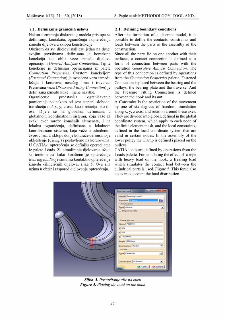
2.1. Definisanje graničnih uslova Nakon formiranja diskretnog modela pristupa se definisanju kontakata, ograničenja i opterećenja između dijelova u sklopu konstrukcije. Obzirom da svi dijelovi naliježu jedan na drugi svojim površinama definisana je kontaktna konekcija kao oblik veze između dijelova operacijom General Analysis Connection. Tip te konekcije je definisan operacijama iz palete Connection Properties. Čvrstom konekcijom (Fastened Connection) je označena veza između ležaja i koturova, nosećeg lima i traverze. Presovana veza (Pressure Fitting Connection) je definisana između kuke i njene navrtke. Ograničenje predstavlja ograničavanje pomjeranja po nekom od šest stepeni slobode: translacija duž x, y, z osa, kao i rotacija oko tih osa. Dijele se na globalna, definisana u globalnom koordinatnom sistemu, koja važe za svaki čvor mreže konačnih elemenata, i na lokalna ograničenja, definisana u lokalnom koordinatnom sistemu, koja važe u određenim čvorovima. U sklopu donje koturače definisano je uklještenje (Clamp) i postavljeno na koturovima. U CATIA-i opterećenja se definišu operacijama iz palete Loads. Za simuliranje djelovanja užeta sa teretom na kuku korišteno je opterećenje Bearing load koje simulira kontaktno opterećenje između cilindričnih dijelova, slika 5. Ova sila uzima u obzir i raspored djelovanja opterećenja.
2.1. Defining boundary conditions After the formation of a discrete model, it is possible to define the contacts, constraints and loads between the parts in the assemlby of the construction. Since all the parts lie on one another with their surfaces, a contact connection is defined as a form of connection between parts with the operation Generative Anaysis Connection. The type of this connection is defined by operations from the Connection Properties palette. Fastened Connection is placed between the bearing and the pulleys, the bearing plate and the traverse. And the Pressure Fitting Connection is defined between the hook and its nut. A Constraint is the restriction of the movement by one of six degrees of freedom: translation along x, y, z axis, and rotation around these axes. They are divided into global, defined in the global coordinate system, which apply to each node of the finite element mesh, and the local constraints, defined in the local coordinate system that are valid in certain nodes. In the assembly of the lower pulley the Clamp is defined i placed on the pulleys. CATIA loads are defined by operations from the Loads palette. For simulating the effect of a rope with heavy load on the hook, a Bearing load which simulates the contact load between the cilindrical parts is used, Figure 5. This force also takes into account the load distribution.
Slika 5. Postavljanje sile na kuku
Figure 5. Placing the load on the hook

Mašinstvo 1(15), 21 – 30, (2018) S. Papić at al: METHODOLOGY, TOOL AND…
26
3. ANALIZA REZULTATA Nakon formiranja MKE modela pristupa se izvođenu proračuna. Uz prethodno pravilno modeliranje, sav posao proračuna vrši CATIA. Vrijeme trajanja proračuna zavisi od kompleksnosti strukture, gustine mreže, broja kontakata i dr. Analizirana su ukupna pomjeranja, von Mises naponi i glavni naponi. Na osnovu ukupnih pomjeranja može se uvrditi krutost sklopa, von Mises naponi ukazuju na mjesta najveće koncentracije napona, a glavni naponi, koji djeluju u okomitim ravnima, ukazuju na naprezanja koja se dešavaju u samo određenim pravcima, pa su stoga upoređeni sa analitičkim proračunom na karakterističnim mjestima konstrukcije. Za teret težine kNQn 70= , vrši se odabir užeta i proračun svih dijelova u sklopu. Nosivost dizalice ima vrijednost [4]:
3. ANALYSIS OF THE RESULTS After the formation of the FEM model the calculations are approached. With previous correct modeling all the calculation is done by CATIA. Duration of calculation depends on structure complexity, mesh density, number of contacts etc. Total displacements, von Mises stresses and main stresses have been analyzed. Based on total displacements it is possible to find the rigidity of the assembly, von Mises stresses indicate the places with highest stress concentration, and main stresses, acting in normal planes, indicate the strains that occur only in certain directions, and these are, therefore, compared with the analytical calculation on characteristic places of construction. For the load of kNQn 70= , the rope selection and calculation of all parts in the assembly is carried out. Load capacity of the crane has the value [4]:
NkNQ
FQ nn 6867067,68
1081.970
1081,9
1 ==⋅
=⋅
== (1)
3.1. Pomjeranja 3.1. Displacements
Slika 6. Ukupno pomjeranje kuke: a) prozor za definisanje prikaza pomjeranja, b) pomjeranje kuke Figure 6. Total displacement of the hook: a) window for defining hook displacement review, b) hook
displacement
Sa slike 6 se može primjetiti da je najveće pomjeranje kuke 0,577mm. 3.2. Von Mises naponi Von Mises ili ekvivalentni napon često se koristi u mehanici čvrstih tijela za predviđanje razvlačenja materijala kod višeosnih opterećenja koristeći rezultate ispitivanja u slučaju jednosonog zatezanja. Definiše se sa [3]:
From figure 6 it can be seen that the biggest movement of the hook is 0,557 mm. 3.2. Von Mises stresses Von Mises or equivalent stress is often used in solid-state mechanics for predicting the streching of materials in multi-axis loads using the results from the case of single-axis tension. It is defined with: [3]:

Mašinstvo 1(15), 21 – 30, (2018) S. Papić at al: METHODOLOGY, TOOL AND…
27
( ) ( ) ( )[ ]213
232
2212 2
13 σσσσσσσσ −+−+−=== Jem (2)
Pri čemu je J2 druga invarijanta napona a 321 ,, σσσ glavni normalni naponi u pravcu osa
x, y, z Analizirajući raspodjelu von Mises naponskih polja najveći napon nastaje na kuki, slika 7, što je i očekivano obzirom na djelovanje opterećenja, i iznosi 167 MPa. 3.3. Glavni naponi Glavni naponi se nazivaju i normalnim naponima zato što su njihovi pravci djelovanja međusobno okomiti [6]. Usvojena je standardna konvencija da je 1σ 32 σσ >> .
Where J2 is the second invariant of stress, and 321 ,, σσσ the main stresses in the direction of
x, y, z axises. Analyzing the distribution of von Mises stress fields, highest stress is generated on the hook, Figure 7, which is expected, due to the action of the load, and it is 167 MPa. 3.3. Main stresses The main stresses are also called normal stresses because their directions of action are mutually normal [6]. A standard convention has been adopted that is 1σ 32 σσ >> .
Slika 7. Von Mises naponi na kuki
Figure 7. Von Mises stresses on the hook U programskom paketu CATIA naponi 1σ , 2σ i
3σ odgovaraju naponima C11, C22, C33 respektivno. Oni daju bolji prikaz stvarnog stanja konstrukcije. Biće prikazani naponi u horizontalnoj (C11) i vertikalnoj ravni (C33) na karakterističnim presjecima kuke i upoređeni sa analitičkim, slika 8. Naponi u karakterističnim presjecima kuke, slika 9, dobijeni analizom u CATIA-i prikazani su na slikama 9, 10 i 11. Ispitivani su naponi u vratu kuke, u krajnjim vlaknima sa unutrašnje strane u horizontalnoj ravni, i u krajnjim vlaknima sa vanjske strane u vertikalnoj ravni, u presjecima A-A i B-B. Može se konstatovati da nema velikih razlika između analitičkog i numeričkog proračuna.
In CATIA software package, the stresses 1σ , 2σ i 3σ correspond to C11, C22, C33, respectively. They give a better picture of the actual state of construction. The stresses in horizontal (C11) and vertical (C33) plane at the characteristic cross-sections of the hook will be shown and compared with the analytical, Figure 8. Stresses on characteristic hook sections, Figure 9, obtained by analysis in CATIA, are shown on Figures 9, 10, 11. The stresses are examined in the hooks neck, in the end fibers from the inside, in the horizontal plane, and in the outer fibers, in the vertical plane, in sections A-A and B-B. It can be noticed that there are no major differences between analytical and numerical calculations.

Mašinstvo 1(15), 21 – 30, (2018) S. Papić at al: METHODOLOGY, TOOL AND…
28
Slika 8. Ukupni napon kuke
Figure 8. Total stress on the hook
Slika 9. Glavni naponi na vratu kuke u vertikalnoj ravni
Figure 9. Main stresses on the hooks neck on the vertical plate
Slika 10. Glavni naponi u presjeku A-A Figure 10. Main stresses in section A-A

Mašinstvo 1(15), 21 – 30, (2018) S. Papić at al: METHODOLOGY, TOOL AND…
29
Slika 11. Glavni naponi u presjeku B-B Figure 11. Main stresses in section B-B
Naponi na presjecima kuke imaju približno iste vrijednosti sa analitički dobijenim naponima. Vrijednosti napona u pojedinim presjecima kuke dobijeni analitičkim proračunom i pomoću CATIA-e, date su u tabeli 1. Odstupanja dobijenih rezultata kreću se do 14,79 %. Imajući u vidu da su za veće napone odstupanja do 0,71 %, može se konstatovati da je ovaj način strukturne analize prihvatljiv.
The stresses in the hook sections have approximately the same values as the analytically obtained stresses. The stress values in some cross sections of the hook obtained by analytical calculation and using CATIA are given in Table 1. The deviations of the obtained results range up to 14.79%. Bearing in mind that for higher stresses deviations range up to 0.71%, it can be concluded that this method of structural analysis is acceptable.
Tabela 1. Naponi na karakterističnim mjestima kuke (MPa) Table 1. Stresses on characteristic hook places (MPa)
Kuka Analitički proračun
MKE analiza Procentualna razlika (%)
Vrat kuke 92,017 92,6 0,63 Presjek A-A
Unutrašnja krajnja vlakna 104,18 103,6 0,56 Vanjska krajnja vlakna -43,05 -49,5 13,03
Presjek B-B
Unutrašnja krajnja vlakna 63,65 63,2 0,71 Vanjska krajnja vlakna -24,68 -21,5 14,79
4. ZAKLJUČAK Strukturna analiza sve više predstavlja neophodan alat za kontrolu i provjeru konstrukcionog rješenja proizvoda u svim poljima inženjerstva. U CATIA-i se strukturna analiza vrši metodom konačnih elemenata, pri čemu se vrši diskretizacija modela odnosno njihova podjela na elemente konačnih dimenzija koji predstavljaju osnovu razmatranja. Pri formiranju MKE modela cilj je što bolje aproksimirati realno stanje konstrukcije, da bi se dobili što bolji rezultati. Posebna pažnja se posvećuje pravilnom definisanju konačnih elemenata, ograničenja,
4. CONCLUSION Structual analysis is more and more an essential tool for controlling and verifying the solution of product construction in all fields of engineering. In CATIA, structural analysis is carried out using the finite element method (FEM), whereby the discretisation of the model and their division into the final dimension elements represents the basis of consideration. When forming an FEM model, the goal is to better approximate real state of the construction, in order to get the best possible results. Special attention is paid to the correct definition of final elements, constraints, loads and mutual contacts. After the formation of an FEM
Mašinstvo 1(15), 21 – 30, (2018) S. Papić at al: METHODOLOGY, TOOL AND…
30
opterećenja i međusobnih kontakata. Nakon formiranja MKE modela pristupa se izvođenju proračuna. Upoređivanjem dobijenih vrijednosti napona može se konstatovati da su naponi približno isti, odnosno odstupanja za veće napone po intenzitetu za dati poprečni presjek iznose do 0,71 %. Osnovni razlog postojanja većih i manjih razlika između dobijenih rezultata je taj što je MKE analiza u CATIA-i ograničena linearnošću materijala i malim mogućim deformacijama. Opšte je poznato da su dobijene vrijednosti pomjeranja tačnije od vrijednosti napona, zato što se naponi dobijaju diferenciranjem pomjeranja pa sadrže grešku. Javljaju se i greške idealizacije, zbog nemogućnosti da se sva složenost realne strukture i njenog okruženja preslika na model. Ali i pored ovih ograničenja osnovni problemi dizajna konstrukcije mogu se riješiti primjenom MKE modula CATIA-e. Rješavanje konstruktivnih problema na ovaj način znatno ubrzava proces projektovanja konstrukcija jer je za kraće vrijeme moguće provjeriti niz varijanti konstruktivnih rješenja, tim prije, ako se uzme u obzir i mogućnosti provjere odabira adekvatnog materijala.
model the calculation are approached. By comparing the obtained stress values, it can be concluded that the stresses are approximately the same, i.e., the deviations for higher stresses by intensity for a given cross section are up to 0,71%. The main reason for existence of larger and smaller differences between obtained results is that the FEM analysis in CATIA is limited by linearity of the materials and small possible deformations. It is generally known that the obtained displacement values are more precise than the stress values, because stresses are obtained by differentiating the displacement so they contain error. There can also appear errors of idealisation, because it is impossible to map the entire complexity of the real structure and its environment to the model. Besides these limitations, the basic design problems can be solved by using the CATIA FEM module. Solving constructive problems in this way greatly accelerates the construction design process, because it is possible to check a range of variants of constructive solutions for a shorter time, even more so, considering the possibility of checking the selection of adequate material.
5. LITERATURA-REFERENCES [1] Hasanović, E.; Metodologija, alati i
mogućnosti strukturne analize mašinske konstrukcije u CAD/CAE sistemu CATIA, Magistarski rad, Mašinski fakultet, Sarajevo, 2017.
[2] Muminović, A., Šarić, I., Mešić, E.; Konstruisanje podržano računarima, Mašinski fakultet, Sarajevo, 2012.
[3] CATIA V5: User documentation [4] Repčić, N., Čolić, M.; Transportna
sredstva, Mašinski fakultet, Sarajevo, 2008.
[5] Sekulović M.; Metod konačnih elemenata 2. izdanje, IRO “Građevinska knjiga”, Beograd, 1988.
[6] Zienkiewicz O.C., Taylor R.L., Zhu J.Z.; The Finite Element Method: Its Basics and Fundamentals, 6th e6ition, Butterworth-Heinemann, Oxford, 2005.
[7] Papić, S., Bašić, H., Klisura, F., Hasanović, E.; Izbor danceta pri projektovanju posuda pod pritiskom pomoću programskog paketa CATIA, 10. Naučno-stručni skup sa međunarodnim učešćem ”QUALITY 2017”, Neum, B&H, 17. - 20 maj 2017.
Coresponding autor: Elida Hasanović, MA mašinstva, FeBoCon doo Sarajevo, Email: [email protected]

Mašinstvo 1(15), 31 – 40, (2018) D. Tiro: THE PROCEDURE OF ESTABLISHING…
31
PROCEDURA OSNIVANJA MIKRO POSTROJENJA OBNOVLJIVIH IZVORA ENERGIJE I ISPLATIVOST INVESTICIJE
THE PROCEDURE OF ESTABLISHING MICRO PLANT OF
RENEWABLE ENERGY SOURCES AND THE PROFITABILITY Tiro Dragi 1University “Džemal Bijedić” Mostar Faculty of Mechanical Engineering Ključne riječi: mikro postrojenje, projekat, dozvola Keywords: micro plant, project, license Paper received: 23.11.2017. Paper accepted: 22.02.2018.
Stručni rad REZIME U ovom radu je opisana procedura otvaranja mikro postrojenja za obnovljive izvore energije u BiH, od ideje do same realizacije projekta, gdje su navedeni koraci i postupci pribavljanja određene dokumentacije i dozvola od strane nadležnih ustanova. Također, navedeni su i toškovi za izdavanje dozvola, kako na nivou opštine tako i na nivou Federacije BiH. Isplativost i vrijeme povrata investicije je dato na kraju rada.
Professional paper
SUMMARY This paper describes the procedure of opening a micro plant for renewable energy sources in Bosnia and Herzegovina, from the idea to the realization of the project, where the steps and acts of obtaining specific documents and licences from the relevant institution are mentioned. The costs for licencing at the municipal level and at the level of the Federation are indicated, too. The profitability and payback period is at the end of the paper.
1. UVOD Na osnovu Pravilnika za mikro-postrojenja obnovljivih izvora energije Mikro-postrojenje OIE znači postrojenje za proizvodnju električne energije iz obnovljivih izvora energije, instalisane snage između 2 kW i 23 kW. Izgradnja mikro postrojenja je poslednjih godina sve popularnija u BiH. Put od ideje do realizacije nije tako jednostavan, ali najvažniji preduslov za primjenu bilo kog projekta obnovljivih izvora energije jesu prirodni resursi, a BiH obiluje obnovljivim izvorima energije. Ova postrojenja imaju izuzetno niske troškove održavanja, ne traže veliko angažovanje radne snage. Prije realizacije samog projekta, potrebno je prikupiti mnoštvo dokumentacije i dozvole od nadležnih ministarstava, opština, preduzeća čija je djelatnost povezana sa energijom, te Federalne Regulatorne komisije za energiju (u daljem tekstu FERK), a inače, kada su obezbjeđene sve potrebne dozvole realizacija projekta (izgradnja postrojenja) se odvija relativno brzo.
1. INTRODUCTION According to the Rulebook for micro-power plants of renewable energy sources, the micro-power plant means a plant for the production of electricity from renewable energy sources with installed power between 2 kW and 23 kW. Construction of micro plants has become more and more popular in Bosnia and Herzegovina in recent years. The road from idea to realization is not so simple, but the most important prerequisite for the implementation of any renewable energy project is natural resources, and BiH abounds in renewable energy sources. These plants have extremely low maintenance costs, and do not require a large number of workers. Prior to the realization of the project, it is necessary to collect a lot of documentation and permits from the competent ministries, municipalities, energy-related enterprises and the Federal Energy Regulatory Commission (hereinafter FERK), otherwise, when all the necessary permits are provided, the implementation of the project (construction of the plant) takes place relatively quickly.

Mašinstvo 1(15), 31 – 40, (2018) D. Tiro: THE PROCEDURE OF ESTABLISHING…
32
2. DOKUMENTACIJA KOJU JE POTREBNO PRIBAVITI 2.1. Dokumentacija iz opštine Prilikom otvaranja mikroenergetskog postrojenja neophodno je dobiti zemljišno-knjižni izvadak, kopiju katastarskog plana i posjedovni list, tako da ovi dokumenti predstavljaju sami početak procedure otvaranja mikro postrojenja za sve vrste obnovljivih izvora energije. U totalu naknada za izdavanje pomenutih zahtjeva iznosi oko 50 KM. Od opštine je potrebno dobiti i urbanističku saglasnost i uz zahtjev za izdavanje urbanističke saglasnosti prilaže se [3] kopija katastarskog plana, vrsta i opis građevine, sa urbanističko – tehničkim uslovima i idejni projekt [5]. Urbanistička saglasnost važi godinu dana od dana njene pravosnažnosti, u tom roku se mora podnijeti zahtjev za odobrenje za građenje [3]. Naknada za zahtjev za izdavanje urbanističke saglasnosti iznosi oko 30 KM, a dokumenti koji se prilažu uz zahtjev moraju biti ovjereni u Opštini oko 20 KM. Naknadu za izdavanje urbanističke saglasnosti iznosi oko 500 KM. Zahtjev za odobrenje za gradnju (građevinsku dozvolu) treba da sadrži: urbanističku saglasnost, dokaz o izmirenim obavezama (renta; naknada za uređ. građ. zemljišta i dr. ), dokaz o pravu gradnje (npr. ZK izvadak i sl.), glavni projekt, pisani izvještaj i potvrda o obavljenoj kontroli odnosno reviziji glavnog projekta. [5]. Naknada za podnošenje zahtjeva odobrenje za gradnju iznosi oko 100 KM, a izdavanje građevinske dozvole oko 1,000 KM. Zahtjev za izdavanje upotrebne dozvole se podnosi istoj instituciji koja je izdala građevinsku dozvolu. Zahtjev se podnosi uz: kopiju odobrenja za gradnju odnosno kopija građevinske dozvole, kopija katastarskog plana, sa ucrtanim položajem građevine, pisana izjava izvođača o izvedenim radovima i uslovima za održavanje građevine, pisani izvještaj nadzornog organa nad gradnjom, u skladu sa zakonaom o građenju. [3] Uz pomenuti zahtjev potrebno je priložiti određene naknade. Naknada za stručno lice za nadzor izgradnje iznosi oko 100 KM, naknada za podnošenje zahtjeva iznosi oko 150 KM. Za tehnički pregled i komisiju za upotrebnu dozvolu potrebno je uplatiti oko 1,000 KM.
2. DOCUMENTATION TO BE TAKEN 2.1. Documentation from the municipality When we wont to open a mocro-power plant, it is necessary to obtain a land registry entry, a copy of the cadastral plan and title deed. These documents represent the very beginning of the procedure for opening a micro-power plant for all types of renewable energy sources. In total, the fee for issuing these documents is about 50 KM. The urbanistic licence is required from the municipality. The request mast have the attachments [3]: copy of the cadastral plan, the type and description of the building, the urban-technical conditions and the conceptual design [5]. The urbanistic licence is valid for one year from the day of its validity, and within that period the application for a building permit must be submitted [3]. The fee for the urbanistic licence application is about 30 KM, and the documents in attachment must be certified in the Municipality about 20 KM. The fee for the urbanistic license by the investor is around 500 KM. The application for a building licence should include: the urbanistic licence, evidence of settled obligations (rent, fee for landscaping, etc.), the land registry entry, the main project, written report and the revision of the main project [5]. The fee for submitting the application is about 100 KM, and the issuing of a building licence is about 1,000 KM. Request for use license to the same instruction which issued the building licence. The application is submitted with: the copy of the building licence or the copy of the building permit, the copy of the cadastral plan with marked position of the building, a written statement by the contractor about the performed works and the maintenance of the building, a written report of the supervising authority on the construction in accordance with the construction law [3]. In addition to the above request, it is necessary to attach certain fees. The fee for the expert for construction supervision is about 100 KM, the fee for submitting the request - 150 KM. It is necessary to pay about 1,000 KM for the technical inspection and the commission for the use license.

Mašinstvo 1(15), 31 – 40, (2018) D. Tiro: THE PROCEDURE OF ESTABLISHING…
33
2.1. Dokumentacija iz Elektroprivrede BIH Budući proizvođač električne energije podnosi zahtjev za prethodnu elektroenergetsku saglasnost u nadležnoj elektrodistribuciji, a kao prilog uz ovaj zahtjev prilaže se slijedeća dokumentacija: kopija katastarskog plana, idejni projekat, planirani vremenski režim proizvodnje, ostala dokumentacija o nosiocu investicije i objektu i dokumenti prema praksi u Opštini / Kantonu, npr. Geodetska podloga s ucrtanom lokacijom objekta i sl. [4]. Uplata za obradu zahtjeva u iznosu od oko 35 KM. Neophodno je pribaviti i elektroenergetsku saglasnost. Zahtjev za elektroenergetsku saglasnost sadrži podatke o podnosiocu zahtjeva, podatke o prethodnoj elektroenergetskoj saglasnosti, podatke o proizvodnom objektu i podatke o planiranju izgradnje. Potrebno je priložiti dokumente: kopiju prethodne elektroenergetske saglasnosti, kopiju odobrenja za građenje, glavni projekat proizvodnog objekta (elektrane), izvod iz projektne dokumentacije: pregled osnovnih energetskih i tehničkih podataka [4]. Potrebno je izvršiti uplatu u iznosu od oko 60 KM. U elektrodistribuciji se podnosi zahtjev za novu elektroenergetsku saglasnost radi povećanja priključne snage, jer je potrebno uskladiti snagu električne energije na mjernom mjestu sa snagom mikro postrojenja. U zahtjevu je potrebno navesti podatke o podnosiocu zahtjeva, o elektroenergetskoj saglasnosti i podatke o objektu i izmijenjenim tehničkim zahtjevima, i priložiti dokumente: kopiju postojeće elektroenergetske saglasnosti, dokaz o izmirenju duga na postojećem mjernom mjestu, projektna dokumentacija i ostala dokumentacija po potrebi [4]. Izvršiti uplatu za obradu zahtjeva u iznosu od oko 60 KM. Cijena povećanja snage priključka zavisi od više faktora, npr. sa 6,7 kW na 10 kW iznosi oko 860 KM. Izgradnja i opremanje mjernog mjesta se vrši od strane elektrodistribucije. Naknada za novi mjerni ormar i mjerni sat iznosi oko 1900 KM. Obavezno se postavlja i rezervno mjerno mjesto čije smještanje košta oko 1,200 KM. Izgradnja i opremanje mikro postrojenja košta približno 3,000 KM/kW, stim što postrojenja manje snage imaju veću cijenu po kW instalisane snage, jer svako postrojenje zahtjeva invertor odnosno pretvarač. Pretvarač je srce sistema koji je povezan na mrežu: koristiti se pretvaranje jednosmjerne struje (DC) u izmjeničnu (AC), a njegova cijena nije mala.
2.1. Documentation from Elektroprivreda BIH The future electricity producer submits a request for preliminary electric power consent in the relevant company for electricity distribution. The attachment of this request is: copy of the cadastral plan, conceptual project, planned time regime of production, other documents of the investitor and the object, the documents according to practice in the municipality / canton, e.g. geodetic footprint with mapped location of the building, etc. [4]. Payment for request processing is about 35 KM. Then, it is also necessary to obtain a electric power consent. The request for the electricity consent shall contain information of the applicant, the preliminary electric power consent, data about the production facility and the construction planning data. Documents in the attachment: a copy of the preliminary electric power consent, a copy of the building license, the main project of micro-power plant, a review of the basic energy and technical data from the main project [4]. It is necessary to make a payment of about 60 KM. It is necessary to harmonize the power of electricity at the measuring point with the power of micro plant. So, a request for the purpose of increasing the connection power is submitted in the company for electricity distribution. The request shall include data of the applicant, the electric power consent and the data about the micro-power plant and the amended technical requirements. The documents in attachment: a copy of the existing electric power consent, evidence of debt settlement at the existing measuring point, project documentation and other documentation as needed [4]. The request processing fee is about 60KM. The cost of increasing the power depends on several factors, e.g. from 6.7 kW to 10 kW is about 860 KM. The construction and equipping of the measuring point is performed by the company for electricity distribution. The fee for the new measuring cabinet and the electric current meter is about 1900 KM. A spare measuring station is obligatory. It costs about 1,200 KM. The construction and equipping of the micro-power plant costs about 3,000 KM per kW, and the lower power plants have a higher price per kW of installed power, because each plant requires an inverter. The inverter is the heart of the system, and it’s connected on the grid: use DC conversion to AC and its price is not small.

Mašinstvo 1(15), 31 – 40, (2018) D. Tiro: THE PROCEDURE OF ESTABLISHING…
34
Probni rad elektrane traje 6 mjeseci, dok se mjerenje kvaliteta električne energije vrši u periodu od najmanje mjesec dana. Mjerenje kvaliteta električne energije vrši ovlaštena firma, a naknada za mjerenje iznosi oko 1000 KM. 2.3. Dokumentacija nadležnih ministarstava i FERK-a Protivpožarnu saglasnost na tehničku dokumentaciju daje MUP kantona, gdje se podnosi zahtjev za traženu saglasnost. Taksa za obradu zahtjeva iznosi oko 23 KM. Energetska dozvola je dokument koji izdaje Federalno ministarstvo energije, rudarstva i industrije. U Ministarstvo potrebno je podnijeti zahtjev za izdavanje, gdje se navode opšti podaci o podnositelju zahtjeva, osnovni tehnički podaci, lokacija i vrsta elektrane, opis proizvodnog dijela elektrane, priključak na elektroenergetski sistem, podaci o kupcima toplotne energije, izjave uz zahtjev. Uz zahtjev se prilažu određeni dokumenti: potvrda o upisu u odgovarajući registar izdatu od nadležne institucije, te registarski i porezni broj podnosioca zahtjeva, izjavu podnosioca zahtjeva o strukturi izvora finansiranja, izjavu podnosioca zahtjeva o svim otvorenim transakcijskim računima kod banaka, uvjerenje o nekažnjavanju podnosioca zahtjeva, idejni projekat, odgovarajući ugovor o koncesiji, ako postoji, studiju o procjeni utjecaja na okoliš, okolinsku dozvolu i vodoprivredna akta, ako su potrebna, prethodnu elektroenergetska saglasnost, dokaz o riješenim imovinsko-pravnim odnosima, urbanistička saglasnost, dokaz o tehničkim i finansijskim mogućnostima, ljudskim resursima, dokaz da se podnosilac zahtjeva ne nalazi u postupku stečaja, dokaz da se podnosilac zahtjeva pridržava obaveze plaćanja poreskih i socijalnih obaveza i drugih doprinosa, informacije u vezi rukovodeće i organizacione strukture podnosioca zahtjeva, sažete biografije rukovodećeg osoblja podnosioca zahtjeva i spisak rukovodećeg osoblja i njihovih kvalifikacija, izjava podnosioca zahtjeva o postojećim dozvolama izdanim od strane FERK-a. Taksa za navedeni zahtjev iznosi 10 KM, a ovjere dokumenata oko 10 KM. Nakon izdavanja dozvole od strane ovog Ministarstva potrebno je uplatiti oko 200 KM za izdavanje energetske dozvole.
The test work of the plant lasts for 6 months. The measurement of the electricity quality is performed for a period of at least one month. It is carried out by an authorized company, and the measurement fee is about 1000 KM. 2.3. Documentation from competent ministries and FERK The firearm consent to the technical documentation is given by the Ministry of Internal Affairs of the Canton. The request processing fee is about 23 KM. The energy licence is a document issued by the Federal Ministry of Energy, Mining and Industry. It is required to submit the request for the energy licence issuing, listing general information about the applicant, basic technical data, location and type of micro-power plant, description of micro- power plant production, connection to the electricity grid, and a statements with the request. Certain documents are enclosed with the application: a certificate of registration in the appropriate registry issued by the competent institution, the applicant's registration and tax number, the applicant's statement about the sources of financing, the applicant's statement on all bank accounts, the certificate of impunity of the applicant, preliminary project; appropriate concession contract, if any; the environmental impact assessment study; environmental and water licence, if necessary; preliminary electric power consent, proof of resolved property-legal relations, the urbanistic licence, proof of technical and financial capabilities, human resources, proof that the applicant is not in the bankruptcy procedure, proof that the applicant complies with the obligations of payment the tax and social obligations and other contributions, information regarding the manager and organizational structure of the applicant, the summarized CV of the managerial staff and a list of managerial staff and their qualifications, a statement by the applicant on existing licenses issued by FERK. The fee for the request is 10 KM, and the validation of documents’ copy is about 10 KM. It is necessary to pay around 200 KM to the Ministry for the issuance of an energy licence.

Mašinstvo 1(15), 31 – 40, (2018) D. Tiro: THE PROCEDURE OF ESTABLISHING…
35
Okolinska dozvola je upravni akt koji izdaje nadležno ministarstvo za postrojenja koji imaju ili mogu imati negativan uticaj na okoliš [5]. Ako se radi o mikro-postojenju koje ne utiče na okoliš, nije potrebno izdavanje okolinske dozvole, ali je neophodno u kantonalnom Ministarstvu okoliša pribaviti potvrdu da nije potrebna okolinska dozvola. Naknada za pomenutu potvrdu iznosi oko 3 KM. Zahtjev za izdavanje dozvole za rad za proizvodnju električne energije u mikro-postrojenjima OIE podnosi se FERK-u. Uz zahtjev se prilaže vrlo slična dokumentacija kao kod Federalnog ministarstva energije, rudarstva i industrije za izdavanje energetske dozvole. [5] Pored ovog podnosioc treba da dokaže da: osigurava kvantitet, kvalitet i kontinuitet, te energetsku efikasnost proizvodnje električne energije, i da vrši isporuku i prodaju električne energije pod uslovima utvrđenim zakonom, primjenjuje savremene tehnologije u korištenju novog elektroenergetskog objekta, posjeduje mjerne uređaje tipa i klase definisanih važećim propisima, zadovoljava i poštuje propisane tehničke i pogonske uslove, ispunjava uspostavljene kriterije za zaštitu okoline i osigurava stalnu kontrolu nad uticajem na bezbjednost ljudi i okoline, vodi baze podataka vezane za obavljanje licencirane djelatnosti, poštuje pravila propisana za tržište električne energije, posjeduje finansijsku i tehničku sposobnost u vezi s korištenjem i održavanjem proizvodnih objekata u skladu sa tehničkim i uslovima zaštite okoline i ispunjava obaveze vezane za zaštitu povjerljivih informacija. [5] Za mikro-postrojenja OIE, ako se radi o fizičkom licu, potrebno je dokazati i da je podnosilac zahtjeva ujedno i krajnji kupac električne energije od jednog od snabdjevača u Federaciji BiH; da je mikro postrojenje OIE locirano u sklopu postojećeg objekta koji već posjeduje brojilo električne energije [5]. Pored navedenih dokumenata, podnosilac uz zahtjev treba da priloži i slijedeće dokumente: uvjerenje da obrt nije u sistemu PDV-a (30 KM), potvrda suda da nije izrečena mjera zabrane rada (14 KM), poslovna evidencija za prethodnu godinu (50 KM), potvrda centralne banke da nije blokiran račun (5 KM), uknjižba mikro postrojenja u gruntovnicu (30 KM). Svi dokumenti koji se prilažu za izdavanje dozvole moraju biti ovjereni pa troškovi za ovjeru iznose oko 70 KM.
The environmental licence is an administrative act issued by the competent ministry for the plants that have or may have a negative impact on the environment [5]. In the case of micro- plant that does not affect the environment the environmental licence isn’t required, but it is necessary to obtain a certificate from the cantonal Ministry of Environment for that. The fee for the certificate is about 3 KM. The request for the issuance of a work licence for the production of electricity in RES micro-power plants shall be submitted to FERK. The application is accompanied by a very similar documentation (attachments), as with the Federal Ministry of Energy, Mining and Industry for issuing an energy licence. [5] In addition to this applicant should prove that: it ensures quantity, quality and continuity, and the energy efficiency of electricity production, and to deliver and sell electricity under the conditions determined by law, apply modern technologies in the use of the new power facility, owns measuring devices of type and class defined by applicable regulations, meets established environmental protection criteria and ensures constant control over the impact on the safety of people and the environment, keeps a database related to the performance of the licensed activity, complies with the rules prescribed for the electricity market, possesses financial and technical capacity related to the use and maintenance of production facilities in accordance with the technical and environmental conditions and fulfills obligations related to the protection of confidential information. [5] For RES micro-power plants, it is necessary to prove that the applicant is also the buyer of electricity from one of the suppliers in the Federation of BiH; Also, it is needed that the micro-power plant is located within the existing facility that already has an electricity meter [5]. In addition to the above mentioned documents, the applicant should also enclose the following documents: the certificate that the company is not in the VAT system (30 KM), confirmation of the court that the company is not prohibited from work (14 KM), the business records for the previous year (50 KM), confirmation by the central bank that the account was not blocked (5 KM), registration of micro-power plant in the land register (30 KM). All documents’ copies must be certified and the certification costs are about 70 KM.

Mašinstvo 1(15), 31 – 40, (2018) D. Tiro: THE PROCEDURE OF ESTABLISHING…
36
2.4. Projektna dokumentacija Izrada idejnog projekta od strane ovlaštene firme košta oko 1200 KM. Cijena za izradu glavnog projekta za mikropostrojenja se kreće okvirno od 1000 do 1200 KM. Kontrolu dokumentacije glavnog projekta vrši pravno lice, registrirano za te poslove. Naknada za izvođenje kontrole glavnog projekta iznosi oko 100 KM. Zatim se vrši revizija projekta kojoj podliježu svi glavni projekti. Naknada za reviziju projekta iznosi oko 60 KM, a zahtjev se podnosi u Ministarstvo privrede gdje se prilaže dokaz o naknadi za vještaka u iznosu od oko 120 KM. 2.5. Registrovanje firme/obrta Na osnovu Člana 85. Zakona o električnoj energiji u Federaciji Bosne i Hercegovine obavezi pribavljanja dozvole za rad za obavljanje djelatnosti proizvodnje električne energije podliježu fizička lica koja su osnovana u skladu sa Zakonom o obrtu i srodnim djelatnostima, i koja će tu djelatnost obavljati u statusu obrtnika, u objektima instalisane snage do 23 kW [5]. U slučaju izgradnje elektrane investitor je dužan da se registruje kao proizvođač el. energije ili doda šifru djelatnosti u okviru postojeće firme. Prvi korak je podnošenje potrebnih dokumenata nadležnoj opštinskoj službi i plaćanje opštinske takse za osnivanje obrta koja iznosi oko 100 KM. Potrebni dokumenti koje treba da pribavi vlasnik za osnivanje obrta su: državljanstvo BiH – dokaz, uvjerenje o poslovnoj sposobnosti u Centru za socijalni rad (11,8 KM), ljekarsko uvjerenje, uvjerenje sa nadležnog suda o nekažnjavanju (13,5 KM), uvjerenje o izmirenim poreznim obavezama (15 KM), svi dokumenti koji se prilažu uz zahtjev moraju biti ovjereni (20 KM). [6] Taksa za otvaranje obrtničke djelatnosti iznosi oko 100 KM. [6] Nakon dobijanja Rješenja o početku obavljanja djelatnosti, potrebno je napraviti pečat (30 – 50 KM). Nakon pečata prvi na redu je ID (identifikacioni) broj i Obavijest o razvrstavanju poslovnog subjekta po šiframa djelatnosti koji izdaje Porezna uprava. Potrebno je u banci otvoriti transakcijski račun. Potrebno je podnijeti Zahtjev za inicijalnu fiskalizaciju. Porezna uprava je na svojoj web stranici objavila spisak aktivnosti obveznika fiskalizacije da bi istima olakšala snalaženje u moru propisa. Fiskalizacija košta u prosjeku 700 KM (uređaj + priključak).
2.4. Projects The preliminary project designing by an authorized company costs about 1200 KM. The price of the main project development for micro-power plants ranges from 1000 to 1200 KM. The control of the main project is carried out by the legal entity registered for these activities. The fee of this control is about 100 KM. Then it is necessary to make the revision of the main project by the Ministry of Economy. The fee for this audit is about 60 KM. The fees for expert hired by the Ministry is about 120 KM. 2.5. Company registration Micro-power plants for the production of electricity can be opened by company or craftsmen according to the Law on Craft and related activities. Craftsmen are obliged to obtain a work licence pursuant to Article 85 of the Law on Electricity in the Federation of Bosnia and Herzegovina. It is just for plants with installed power up to 23 kW [5]. The investor is obliged to register as a producer of electric energy or adds the activity code within the existing company. The first step is to submit the necessary documents to the relevant municipal service and to pay a municipal fee for establishing the craft, which is about 100 KM. The necessary documents are: Citizenship of Bosnia and Herzegovina, certificate of business ability at the Center for Social Work (KM 11.8), medical certificate, certificate from the competent court on impunity (KM 13.5) and settled tax liabilities (15 KM). All documents’ copies in the application attachment must be certified (20 KM). [6] The fee for opening a craft business is about 100 KM. [6] Upon receipt of the Decision on starting the activity, a seal should be made (30-50 KM). After that, it is necessary to obtain the ID (identification) number and the Notice on the classification of a business entity by activity codes issued by the Tax Administration. It is necessary to open a transaction account at a bank. The next request is for initial fiscalization. The Tax Administration has published on its website a list of the activities of the taxpayer to facilitate easier navigation in the sea of regulations. Fiscalization costs an average of 700 KM (device + connection).

Mašinstvo 1(15), 31 – 40, (2018) D. Tiro: THE PROCEDURE OF ESTABLISHING…
37
Postupak fiskalizacije može potrajati, čak i po nekoliko mjeseci. Međutim, to ne znači da obrtnik ne može obavljati djelatnost bez fiskalnog uređaja. Ukupni troškovi osnivanja obrta se, posmatrajući razne opštine u FBiH, kreću od 885 do 937 KM, a postupak traje oko 15 dana. 2.6. Operator za obnovljive izvore energije i efikasnu kogeneraciju Investitor podnosi zahtjev Operatoru za obnovljive izvore energije i efikasnu kogeneraciju (dalje u tekstu OIEiEK) za upis u Registar OIEiEK. Uz navedeni zahtjev je potrebno priložiti: urbanističku saglasnost, energetsku dozvolu i građevinsku dozvolu. [7] Uz zahtjev se prilažu ovjereni dokumenti (20 KM) i naknada za upis u Registar OIEiEK koja iznosi 100 KM. Zahtjev za sticanje statusa potencijalnog privilegovanog proizvođača električne energije se, takođe, podnosi OIEiEK. Uz zahtjev se prilaže: izvod iz sudskog registra nadležnog suda, registarski i porezni broj, potvrda poslovne/komercijalne banke, izjavu podnosioca zahtjeva o svim otvorenim transakcijskim računima kod komercijalnih banaka, glavni projekt, energetsku dozvolu, pravosnažnu građevinsku dozvolu, prethodnu elektroenergetsku saglasnost, dokaz o riješenim imovinsko-pravnim odnosima [7]. Naknada za zahtjev iznosi oko 200 KM, a ovjera dokumentacije oko 20 KM. Da bi postrojenje stupilo u rad podnosi se zahtjev OIEiEK za zaključenje ugovora o otkupu električne energije iz OIE iz postrojenja u probnom radu uz naknadu od 200 KM. Uz zahtjev se prilažu skoro isti dokumenti kao i za prethodno objašnjeni zahtjev, a uz to još i upotrebna dozvola za postrojenje, elektroenergetska saglasnost, ugovor o priključenju na distributivni sistem, sa potvrdom nadležnog operatora da je mjerno mjesto postrojenja izvedeno u skladu sa važećim propisima i pravilima, ugovor o snabdijevanju električnom energijom. [7] Nakon završenog probnog rada (6 mjeseci) podnosi se zahtjev za ugovor o otkupu električne energije iz OIE po referentnoj cijeni, uz naknadu od 50 KM. Dokumentacija koja se prilaže je skoro ista, samo treba priložiti i dozvolu za rad - licencu za obavljanje djelatnosti, koja sadrži i dokaz o sticanju statusa kvalifikovanog proizvođača [7]. Naknada za ovjerene dokumente iznosi oko 35 KM.
The fiscalization process may take a few months. However, this does not mean that a craftsman can not perform an activity without a fiscal device. The total cost of establishing a craft is from 885 to 937 KM for various municipalities in FBiH, and the procedure lasts about 15 days. 2.6. Operator for Renewable Energy Sources and Efficient Cogeneration The Investor submits a request to the Operator for Renewable Energy Sources and Efficient Cogeneration (hereinafter OIEiEK) for registration in the OIEiEK Register. In attachment it is necessary to enclose: urban licence, energy permit and building licence. [7] Certified copies of documents (20 KM) and registration fees for the OIEiEK Registry (100 KM) shall be enclosed with the application. The request for obtaining the status of a potential privileged electricity producer is also submitted to the OIEiEK. The attachments are: the extract from the court register of the competent court, registration (ID) and tax number, business / commercial bank certificate, statement of the applicant on all opened transaction accounts at commercial banks, main project, energy licence, building licence, the evidence on settled property-legal relations [7]. The fee for the application is about 200 KM, and the documentation’s copies validation is about 20 KM. The investor must conclude an agreement on the purchase of electric energy in the period of micro-power plant testing. The fee for the contract is 200 KM. With the application for the contract, almost the same documents as for the previously explained request are attached, along with the use licence, the electric power consent, the agreement about connection to the grid, with confirmation from the competent operator that the measuring station has been carried out in accordance with applicable regulations and rules, and the contract for electricity supply. [7] After the completion of the trial work (6 months), the investor gives the request for another contract - for electricity purchase from the micro-power plant at the reference price. The fee is 50 KM. The documentation that is enclosed is almost the same, it should only be accompanied by a work licence, which also includes proof of acquiring the status of a qualified producer [7]. The fee for certified copies of documents is about 35 KM.

Mašinstvo 1(15), 31 – 40, (2018) D. Tiro: THE PROCEDURE OF ESTABLISHING…
38
3. VISINA INVESTICIJE U tabeli 1. su prikazani svi potrebni dokumenti po redoslijedu kako ih je potrebno pribaviti, te određene naknade i period čekanja za iste. Navedene cijene za određene naknade su okvirne.
3. HEIGHT OF INVESTMENT All required documents are shown in Table 1 in the order they need to be obtained, as well as certain fees and waiting periods. The quoted prices for certain fees are indicative.
Tabela 1. Specifikacija potrebnih dokumenata za osnivanje mikro postrojenja za OIE Table 1. Specification of required documents for the establishment of micro-power plant RES
Dokument - Document Period čekanja Period of waiting
Cijena ( KM)Price( KM)
ZK izvadak - Land Registry entry 7 dan (days) 10 Katastarski plan i posjedovni list Cadastral plan and possessory paper
20 dana 40
Idejni projekat - Preliminary project 40 dana 1200 Urbanistička saglasnost - Urban licence 30 dana 550 Prethodna elektroenergetska saglasnost Previous electrical-energy agreement
40 dana 35
Izrada glavnog projekta - Main project 40 dana 1200 Kontrola glavnog projekta - Control of main project 7 dana 100 Građevinska dozvola - Building license 30 dana 1100 Protivpožarna saglasnost - Fire-prevention agreement 7 dan 23 Elektroenergetska saglasnost - Electrical-energy agreement 40 dana 60 Registrovanje obrta - Registration of craft 15 dana 935 Upis u registar OIEiEK - Admission into the register RES and EC 10 dan 120 Revizija glavnog projekta - Revision of main project 25 dana 180 Povećanje priključne snage - Increase in Connected Power 30 dana 921 Okolinska dozvola - Enviromental licence 7 dana 3 Energetska dozvola - Energy licence 7 mjeseci 220 Status potencijalnog privilegovanog proizvođača u OIEiEK Status of potential privileged producer in RES
2 mjeseca 220
Izgradnja i opremanje mjernog mjesta The construction and equipping of the measuring point
30 dana 3073
Izgradnja i opremanje postrojenja – Construction and equipment of plant
10 dana cca. 3000/kW
Upotrebna dozvola - Use license 40 dana 1227 Ugovor o otkupu el. energije u probnom radu Contract of repurchase of electric energy in probition
6 mjeseci 200
Mjerenje kvaliteta el. energije u probnom radu Measuring quality of electric energy in probition
1 mjesec 800
Dozvola za rad - Work licence 2 mjeseca 199 Ugovor o otkupu el. energije - Contract of repurchase of electric energy
1 mjesec 85
Ukupno - Total: ≈ 3 godine 12 501 U tabeli 1. u ukupnu cifru nije uračunata cijena za izgradnju i opremanje postrojenja, jer ona zavisi od instalisane snage postrojenja i mijenja se u zavisnosti od potreba investitora (1 kW nazivne snage postrojenja iznosi oko 3.000 KM), pa tako npr. ukupna cijena za osnivanje mikropostrojenja od 5 kW iznosi oko 27.500 KM. Za osnivanje mikropostrojenja od npr. 10 kW iznosi oko 42.500 KM, itd.
Table 1 in the total figure does not include the cost of building and equipping the plant, because it depends on the installed power plants and changes, depending on the needs of investors (1 kW is around 3,000 KM), so for example, the total cost for the establishment of a micro plant of 5 kW is approximately 27,500 KM. For micro plant of 10 kW it is approximately 42.500 KM, etc.

Mašinstvo 1(15), 31 – 40, (2018) D. Tiro: THE PROCEDURE OF ESTABLISHING…
39
4. ISPLATIVOST I VRIJEME POVRATA INVESTICIJE 4.1. Mikropostrojenja koja nemaju status privilegovanog proizvođača Otkupna cijena električne energije od strane Operatora OIEiEK za solarna mikropostrojenja koja nemaju status privilegovanog proizvođača je 0,105858 KM/kWh. Ako se kao primjer uzme da jedno prosječno mikropostrojenje proizvede godišnje 1100kWh po kW instalisane snage, to znači da mikropostrojenje instalisane snage 10kW proizvede 11000kWh električne energije. Ukupna zarada od proizvedene el. energije je: 11000kWh · 0,105858KM/kWh = 1164KM. Ako je za postrojenje od 10kW uloženo 42500KM, za povrat investicije potrebno: 42500 / 1164 = 36,5 godina. Ako kao primjer uzmemo postrojenje od 5kW instalisane snage, tada je godišnja proizvodnja oko 5500kWh, pa je godišnja zarada: 5500kWh · 0,105858 KM/kWh = 582KM. Ako je za postrojenje od 5kW uloženo 27500KM, to znači da je za povrat investicije potrebno: 27500 / 582 = 47,3 godina. Za postrojenje maksimalne instalisane snage za mikropostrojenja – 23kW, analognim proračunom dobijamo da bi period povrata bio: 1100kWh/kW · 23kW = 25300kWh 25300kWh · 0,105858 KM/kWh = 2678,2 KM 81500KM / 2678,2 KM = 30,4 godine. Ovde treba naglasiti da je za proračun uzeto da jedan kW instalisane snage proizvede godišnje1100kWh. Neka postrojenja mogu imati malo veću, a neka malo manju proizvodnju, ali to ne može znatno izmjeniti broj godina povrata investicije. U proračun nije uzeto održavanje postrojenja i eventualni kvarovi, mjerenja i kontrole, a sve to još više produžava period povrata investicije. 4.2. Mikropostrojenja koja imaju status privilegovanog proizvođača Otkupna cijena električne energije od strane Operatora OIEiEK za solarna mikropostrojenja koja imaju status privilegovanog proizvođača je oko 0,54KM/kWh, a to je oko 5,4 puta više od cijene za solarna mikropostrojenja koja nemaju status privilegovanog proizvođača. To znači da će period povrata investicije ovde biti 5,4 puta kraći, tj: za mikropostrojenje instalisane snage 5kW to je oko 8,8 godine; za mikropostrojenje instalisane snage 10kW to je oko 6,8 godine; za mikropostrojenje instalisane snage 23kW to je oko 5,6 godina.
4. THE PROFITABILITY AND TIME OF THE INVESTMENT RETURN 4.1. Micro-power plants without the status of privileged producer The purchase price of electricity by the OIEiEK for solar micro-power plants without the status of privileged producer is 0,105858KM per kWh. If, for example, one average micro-power plant produces annually 1100 kWh per kW of installed power, this means that the micro-power plant with installed power of 10 kW produces 11000 kWh of electricity. Total earnings from produced el. energy is: 11000kWh · 0,105858KM / kWh = 1164KM. If 42500KM is invested for a plant of 10kW, a return on investment is required: 42500/1164 = 36.5 years. If as an example we take the plant of 5kW installed capacity, then the annual production is about 5500kWh, so the annual salary: 5500kWh · 0,105858KM / kWh = 582KM. If 27500KM is invested for a 5kW plant, this means that the return on investment is: 27500/582 = 47.3 years. For the installation of the maximum installed power for micro-power plants - 23kW, we receive with analogue calculation that the return period would be: 1100kWh / kW · 23kW = 25300kWh 25300kWh · 0,105858KM/kWh = 2678,2 KM 81500KM / 2678,2 KM = 30,4 years. It should be emphasized here that for the calculation it is assumed that one kW of installed power produces annually 1100kWh. Some plants may have a slightly larger, and some slightly less production, but this cannot significantly change the number of years of investment return. No mainte-nance of the plant and possible failures, measure-ments and controls were taken into account, and all this extends the investment return period even further. 4.2. Micro-power plants with the status of privileged producer The purchase price of electricity by the OIEiEK Operator for solar power plants with the status of a privileged producer is around 0.54KM / kWh, which is about 5.4 times higher than the price for solar micro-power plants that do not have the status of a privileged producer. This means that the investment return period will be 5.4 times shorter, i.e.: for the micro-power plants with the installed power of 5kW, this is about 8.8 years; for the micro-power plants with the installed power of 10kW it is about 6.8 years; for the micro-power plants with the installed power of 23kW it is 5.6 years.

Mašinstvo 1(15), 31 – 40, (2018) D. Tiro: THE PROCEDURE OF ESTABLISHING…
40
5. ZAKLJUČAK Procedura otvaranja mikropostrojenja za obnovljive izvore enegrije u BiH i FBiH je veoma složen i dugotrajan proces zbog dokumentacije koju je potrebno prikupiti, a čitava procedura zavisi od nadležnih institucija. Kako je u ovom radu utvrđeno, ta procedura traje 3 godine, što je nedopustivo. Vrijednost investicije zavisi od planirane snage koja će se instalisati, kao i od tehničkih uslova priključenja. Najnižu cijenu za mikropostrojenja po kW imaju veći projekti npr. 23kW. Obnovljivi izvori energije ne zagađuju okoliš i zemlja bi trebala ići na supstituciju energetskih izvora obnovljivim izvorima energije. Izgradnja solarnih elektrana poslednjih godina sve je popularnija, ali za budući razvoj vrlo je bitna podrška države. Država bi trebala obezbjediti jasno propisane i što kraće procedure za dobijanje potrebnih dozvola i saglasnosti, kao i novim investitorima davati status privilegovanih proizvođača, što bi u mnogome olakšalo primjenu obnovljivih izvora energije. Kako je ova studija pokazala, apsolutno se ne isplati investirati u mikropostrojenja ako ona neće proizvoditi električnu energiju koja će biti otkupljena po cijeni za privilegovane proizvođače, jer se ne mogu vratiti ni uložena sredstva, a kamoli ostvariti profit. Zbog toga sva mikropostrojenja moraju biti privilegovani proizvođači.
5. ZAKLJUČAK The procedure for opening micro-power plant for renewable energy sources in BiH and FBiH is a very complex and time-consuming process due to the documentation that needs to be collected, and the entire procedure depends on the competent institutions. As found in this paper, this procedure lasts for 3 years, which is unacceptable. The investment depends on the planned power to be installed, as well as on the technical conditions of connection on the grid. The lowest price per kW is larger projects, for example, 23kW. Renewable energy sources do not pollute the environment, and the country should substitute the energy sources with renewable ones. Construction of solar power plants in recent years is becoming increasingly popular, but for the future development, the support of state is very important. The state should provide clearly prescribed and shorter procedures to obtain the necessary permits and licences, as well as to give the status of privileged producers to the investors, which would greatly facilitate the use of renewable energy sources. As this study has shown, it is absolutely not worthwhile to invest in micro-power plants if they do not produce electricity at the price of privileged producers, because they cannot return the investment, and cannot make a profit. Therefore, all micro-power plants must be privileged producers.
5. LITERATURA - REFERENCES [1] Herzog, A. V., Timothy E. L., and
Kammen D. M..: Renewable energy sources, Encyclopedia of Life Support Systems (EOLSS), 2001
[2] Abdilahi A. M, Yatim A. H. M, Wazir M., Khalaf O. T., Shumran A. F, Nor F. M, Feasibility study of renewable energy-based microgrid system in Somaliland׳s urban centers, Renewable and Sustainable Energy Reviews, Volume 40, December 2014
[3] http://www.mostar.ba/odjel-za-urbanizam.html
[4] http://www.elektroprivreda.ba/stranica/zahtjevi
[5] http://www.fbihvlada.gov.ba/bosanski/zakoni/
[6] http://poslovnisvijet.ba/registracija-obrta-u-bih-potrebno-vrijeme-i-troskovi/
[7] http://www.operatoroieiek.ba Coresponding author: Tiro Dragi University of “Džemal Bijedić” Mostar Faculty of Mechanical Engineering Email: [email protected] Phone: +387 61 482 143

Mašinstvo 1(15), 41-48, (2018) R.Hadžović, et al.: CALCULATION INDEX OF ….
41
PRORAČUN INDEKSA POUZDANOSTI NA PRIMJERU NADSTREŠNICE ČELIČNE HALE, USPOREDBA PTP i EC-1
PROPISA ZA OPTEREĆENJE SNIJEGOM
CALCULATION INDEX OF RELIABILITY ON THE EXAMPLE OF THE SHED OF A STEEL HALL, COMPARATION OF PTP AND EC-1
REGULATIONS FOR SNOW LOAD
Hadžović Rašid1 Redžić Vahid2 Redžić Nermin2 1University “Džemal Bijedić” Civil Engineering Faculty 2University of Zenica, Polytechnic faculty Ključne riječi: indeks pouzdanosti, normirano opterećenje snijegom, karakteristično opterećenje snijegom Keywords: reliability index, standardized load, snow load, characteristic snow load Paper received: 13.09.2017. Paper accepted: 05.12.2017.
Stručni rad REZIME U radu izvršen je proračun čelične nadstešnice u Drvaru u skladu sa važećim tehničkim propisima za snijeg iz 1961. godine i EC-1 propisima. Cilj ovog rada je probabilističkim postupkom provjeriti pouzdanost nosača, odnosno izvršiti kalibraciju čelične nadstrešnice proračunate klasičnim determinističkim postupkom. Statički sistem čelične nadstrešnice je prosta greda datog raspona, slika br.1. Čelični profili su valjani INP profili datih statističkih parametara. Međusobni razmak nosača iznosi λ = 2,4 m. Potrebno je proračunati indekse pouzdanosti u tački 1 (jer su tu mjerodavni statički uticaji i pomjeranja za oba granična stanja) u skladu sa jednačinama graničnih stanja.
Professional paper
SUMMARY This paper deals with the resistance of the shed of a steel hall in Drvar according to technical regulations for snow from 1961 and EC1 regulations. The paper aims to check the reliability of the shed with probabilistic approach. That also implies calibration of the steel hall construction analyzed with classic deterministic method. Statical system of the shed of a steel hall is a beam with a given span, Figure 1. Steel sections are hot rolled INP sections with specified statistic parameters. The length of the beam span is λ = 2,4 m. The reliability indexes have to be analyzed in point 1(relevant statical forces and displacements for ULS and SLS) and according to equations of limit states.
1. UVOD U decembru 1999. i februaru 2012. godine usljed velikih padavina snijega značajan broj objekata doživio je manja ili veća oštećenja. Oštećenja su nastala na različitim vrstama nosača i materijala, ali su najčešće stradale čelične konstrukcije, za koje je snijeg dominantno opterećenje. Dosadašnje vjerovanje je da su proračunati objekti “apsolutno sigurni”, ukoliko se opterećenja pomnože sa globalnim koeficijentom sigurnosti, da naponi budu manji od dopuštenih, a da ugibi budu u dozvoljenim granicama. U današnje vrijeme se provode probabilistički proračuni postojećih objekata -kalibracija konstrukcija u cilju dobivanja indeksa pouzdanosti na osnovu kojeg se može donijeti zaključak o pouzdanosti postojećih konstrukcija u Bosni i Hercegovini.
1. INTRODUCTION Due to extreme snowfall in December 1999 and in February 2012 significant number of objects suffered smaller or serious damage. The damage appeared on different kinds of girders and materials but mostly on steel structures because on those structures snow is the dominant load. Analyzed objects are “absolutely safe” because the analyzed load values are multiplied by the safety coefficient so that the stress levels were under the allowed values and deflection values were within allowed limits. Nowadays existing objects are analyzed with probabilistic approach-calibration of constructions aimed to determine reliability index. The result is getting a conclusion of reliability of existing
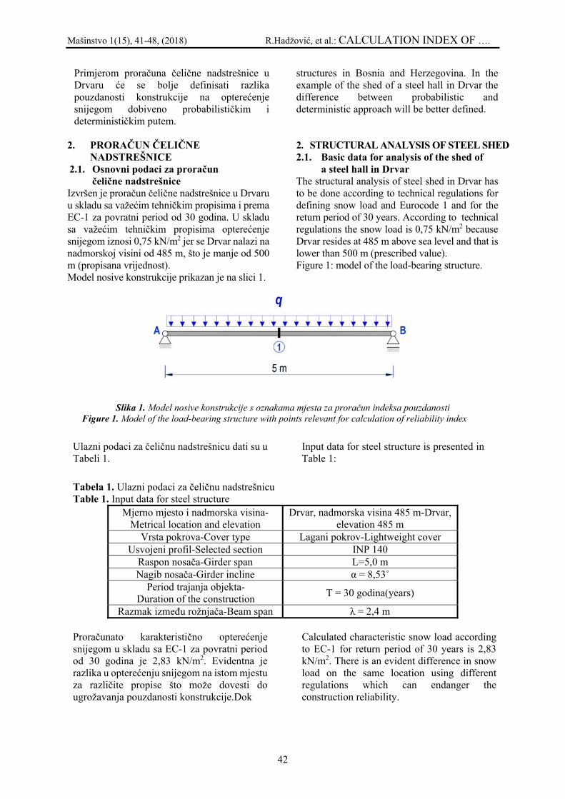
Mašinstvo 1(15), 41-48, (2018) R.Hadžović, et al.: CALCULATION INDEX OF ….
42
Primjerom proračuna čelične nadstrešnice u Drvaru će se bolje definisati razlika pouzdanosti konstrukcije na opterećenje snijegom dobiveno probabilističkim i determinističkim putem.
2. PRORAČUN ČELIČNE
NADSTREŠNICE 2.1. Osnovni podaci za proračun
čelične nadstrešnice Izvršen je proračun čelične nadstrešnice u Drvaru u skladu sa važećim tehničkim propisima i prema EC-1 za povratni period od 30 godina. U skladu sa važećim tehničkim propisima opterećenje snijegom iznosi 0,75 kN/m2 jer se Drvar nalazi na nadmorskoj visini od 485 m, što je manje od 500 m (propisana vrijednost). Model nosive konstrukcije prikazan je na slici 1.
structures in Bosnia and Herzegovina. In the example of the shed of a steel hall in Drvar the difference between probabilistic and deterministic approach will be better defined.
2. STRUCTURAL ANALYSIS OF STEEL SHED 2.1. Basic data for analysis of the shed of
a steel hall in Drvar The structural analysis of steel shed in Drvar has to be done according to technical regulations for defining snow load and Eurocode 1 and for the return period of 30 years. According to technical regulations the snow load is 0,75 kN/m2 because Drvar resides at 485 m above sea level and that is lower than 500 m (prescribed value). Figure 1: model of the load-bearing structure.
Slika 1. Model nosive konstrukcije s oznakama mjesta za proračun indeksa pouzdanosti Figure 1. Model of the load-bearing structure with points relevant for calculation of reliability index
Ulazni podaci za čeličnu nadstrešnicu dati su u Tabeli 1.
Input data for steel structure is presented in Table 1:
Tabela 1. Ulazni podaci za čeličnu nadstrešnicu Table 1. Input data for steel structure
Mjerno mjesto i nadmorska visina-Metrical location and elevation
Drvar, nadmorska visina 485 m-Drvar, elevation 485 m
Vrsta pokrova-Cover type Lagani pokrov-Lightweight cover Usvojeni profil-Selected section INP 140
Raspon nosača-Girder span L=5,0 m Nagib nosača-Girder incline α = 8,53˚
Period trajanja objekta- Duration of the construction T = 30 godina(years)
Razmak između rožnjača-Beam span λ = 2,4 m Proračunato karakteristično opterećenje snijegom u skladu sa EC-1 za povratni period od 30 godina je 2,83 kN/m2. Evidentna je razlika u opterećenju snijegom na istom mjestu za različite propise što može dovesti do ugrožavanja pouzdanosti konstrukcije.Dok
Calculated characteristic snow load according to EC-1 for return period of 30 years is 2,83 kN/m2. There is an evident difference in snow load on the same location using different regulations which can endanger the construction reliability.

Mašinstvo 1(15), 41-48, (2018) R.Hadžović, et al.: CALCULATION INDEX OF ….
43
normirano opterećenje snijegom iznosi 0,75 kN/m2 (n.v. Drvara je 485 m, što je manje od 500 m).
2.2 .Analiza opterećenja na čeličnu
nadstrešnicu Stalno opterećenje:
- krovni panel Al-lim 2x1 poliuretan, kao ispuna 0,15 kN/m2
- spojnice i veze 0,05 kN/m2 0,20 kN/m2 na nosač nadstrešnice: 0,20*λ = 0,20*2,40 = 0,48 kN/m
- vlastita težina nosača (INP 140) 0,144 kN/m g = 0,624 kN/m
Opterećenje snijegom prema PTP na nadstrešnici Snorm = 0,75 kN/m2 x 2,4 m x 0,8 = 1,44 kN/m Mjerodavna kombinacija opterećenja za usvajanje profila:
q = 0,624 kN/m + 1,44 kN/m = 2,064 kN/m Opterećenje snijegom prema EC-1: SK = 2,83 kN/m2 x 2,4 m x 0,8 = 5,43 kN/m Mjerodavna kombinacija opterećenja: q = 0,624 kN/m + 5,43 kN/m = 6,05 kN/m 2.3. Rezultati statičkog proračuna Na sljedećim slikama biće prikazani rezultati statičkog proračuna za opterećenje iz 2.2. Rezultati se odnose na momente savijanja,transverzalne sile, normalne napone, smičuće napone i ugibe. Za statičku analizu korišten je softerski paket Radimpex Tower 6.0.
Determined snow load come to 0,75 kN/m2 (elevation of Drvar is 485 m which is less than 500 m). 2.2. Load analysis for steel shed in Drvar Dead load:
- roof panel Al-sheet metal 2x1 polyurethane as fill material 0,15 kN/m2
- joints and connections 0,05 kN/m2 0,20 kN/m2
on the beam: 0,20*λ = 0,20*2,40 = 0,48 kN/m
- weight of the beam (INP 140) 0,144 kN/m g= 0,624 kN/m
Snow load according to PTP on a shed: Sdet = 0,75 kN/m2 x 2,4 m x 0,8 = 1,44 kN/m’ Relevant load combination for choosing sections:
q = 0,624 kN/m' + 1,44 kN/m' = 2,064 kN/m' Snow load according to EC-1: SK = 2,83 kN/m2 x 2,4 m x 0,8 = 5,43 kN/m Relevant load combination: q = 0,624 kN/m + 5,43 kN/m = 6,05 kN/m 2.3. Results of structural analysis The results of structural analysis for load from 2.2. will be presented in the following Figures. Results refer to bending moment, shear force, normal stress, shear stress and deflections. Software package Radimpex Tower 6.0 is used for structural analysis.
Slika 2. Dijagram momenata savijanja za mjerodavnu kombinaciju opterećenja (kNm) Figure 2. Bending moment diagram for relevant load combination (kNm)

Mašinstvo 1(15), 41-48, (2018) R.Hadžović, et al.: CALCULATION INDEX OF ….
44
Slika 3. Dijagram transverzalnih sila za mjerodavnu kombinaciju opterećenja (kN) Figure 3. Shear force diagram for relevant load combination (kN)
Slika 4. Dijagram ugiba za mjerodavnu kombinaciju opterećenja (mm) Figure 4. Deflection diagram for relevant load combination (mm)
Slika 5. Dijagram normalnih napona za mjerodavnu kombinaciju opterećenja (MPa) Figure 5. Normal stress diagram for relevant load combination (MPa)
Slika 6. Dijagram smičućih napona za mjerodavnu kombinaciju opterećenja (MPa) Figure 6. Shear stress diagram for relevant load combination (MPa)

Mašinstvo 1(15), 41-48, (2018) R.Hadžović, et al.: CALCULATION INDEX OF ….
45
INP 140 → Wx = 81,9 [cm3]; Ix = 573 [cm4]; Sx = 47,7 [cm3]; s = 5,7 [mm]; E = 210000 [MPa]; A = 18,2 [cm2]; G = 0,143 [kN/m'] dopušteni napon: σdop = σF/ν = 240/1,5 = 160 [MPa] ν = 1,5 - globalni koeficijent sigurnosti Kontrola normalnih napona: σmax = Mmax
Wx = 78,80 MPa < σdop=160 [MPa]
Kontrola smičučih napona:
τmax = Tmax·Sx
s·Ix = 6,51 MPa < τdop=90 [MPa]
Kontrola ugiba:
vmax = 1,3359 cm < vdop = L
200 =
500200
= 2,5 [cm] USVOJEN PROFIL: INP 140! 2.4. Probabilistički proračun U nastavku su proračunati indeksi pouzdanosti prema propisanom karakterističnom opterećenju snijegom prema EC-1 za Drvar na prethodno dimenzioniranoj konstrukciji u skladu sa PTP sa ciljem kalibracije konstrukcije.
INP 140 → Wx = 81,9 [cm3]; Ix = 573 [cm4]; Sx = 47,7 [cm3]; s = 5,7 [mm]; E = 210000 [MPa]; A = 18,2 [cm2]; G = 0,143 [kN/m'] allowable stress: σall = σF/ν = 240/1,5 = 160 [MPa] ν = 1,5 - global safety coefficient Normal stress check:
σmax = Mmax
Wx = 78,80 MPa < σall=160 [MPa]
Shear stress check:
τmax = Tmax·Sx
s·Ix = 6,51 MPa < τall=90 [MPa]
Deflection check:
vmax = 1,3359 cm < vdop = L
200 =
500200
= 2,5 [cm] SELECTED SECTION: INP 140! 2.4. Probabilistic analysis In the sequel the indexes of reliability will be calculated according to EC-1 for characteristic snow load in Drvar on previously designed construction according to PTP aiming to construction calibration.
Tabela 2. Bazne varijable otpornosti konstrukcije [1] Table 2. Base variables of structure resistance [1]
BAZNE VARIJABLE OTPORNOSTI
Varijabla-Variable
Srednja vrijednost-Average value V Raspodjela-
Distribution Opis bazne varijable-
Description of base variable
X1 30,9 kN/cm2 0,1 Weibull-ova (Weibull)
Granica popuštanja-Yield strength
X2 18,2 cm2 0,05 Normalna-Normal Površina poprečnog presjeka-Cross section area
X3 81,9 cm3 0,05 Normalna-Normal Moment otpora-Moment of resistance
X4 l/200 = 2,5 cm 0,1 Normalna-Normal Limitirani pomak nosača-Limited displacement of
girder

Mašinstvo 1(15), 41-48, (2018) R.Hadžović, et al.: CALCULATION INDEX OF ….
46
Proračunate vrijednosti indeksa pouzdanosti za povratni period od 30 godina 1 su: βnorm = 3,82 za GSN (granično stanje nosivosti) 2.1. βnorm = 1,58 za GSN (granično stanje upotrebljivosti) 2.2. Proračun je izvršen metodom FORM – metoda pouzdanost prvog reda pomoću programskog paketa STRUREL (Comrel).
Calculated values of reliability index for return period of 30 years: βnorm = 3,82 for ULS (ultimate limit state) 2.1. βnorm = 1,58 za for SLS (serviceability limit state) 2.2. In the analsis is used FORM method of reliability of first row using the software package STRUREL(Comrel).
Tabela 3. Bazne varijable dejstava na konstrukciju iz 2.2 Table 3. Base variables actions on structure from 2.2.
BAZNE VARIJABLE DEJSTVA -BASE VARIABLES OF ACTIONS
Varijabla-Variable
Srednja vrijednost-Average value V Raspodjela-
Distribution
Opis bazne varijable-Description of base
variable
Y1 0,624 kN/m 0,05 Normalna-Normal Stalno dejstvo-Dead load
Y2 S1,S2 V1,V2 Gumbel Dejstvo snijega-Snow load
Tabela 4. Proračunate vrijednosti indeksa pouzdanosti β za opterećenje snijegom prema PTP Table 4. Calculated values of reliability index β for determined load TAČKE NA KONSTRUKCIJI-POINTS ON
CONSTRUCTION Vrijednost indeksa pouzdanosti β - Value of reliability
index obtained from the regulated snow Granično stanje nosivosti – GSN
Ultimate limit state - ULS 1 6,49
Granično stanje upotrebljivosti – GSU Serviceability limit state - SLS 1 1,65
Tabela 5. Proračunate vrijednosti indeksa pouzdanosti β za opterećenje snijegom prema EC-1 (bold označene vrijednosti su manje od preporučenih vrijednosti iz Eurocode-a 1) Table 5. Calculated values od reliability index for snow load according to EC-1 (bold marked values are lower from recommended values in Eurocode 1
TAČKE NA KONSTRUKCIJI-POINTS ON CONSTRUCTION
Vrijednost indeksa pouzdanosti β - Value of reliability index obtained from the regulated snow
load Granično stanje nosivosti - GSN
Ultimate limit state - ULS 1 1,76
Granično stanje upotrebljivosti - GSU Serviceability limit state - SLS 1 -2,34
U tabelama br. 4. i br. 5. su date vrijednosti proračunatih indeksa pouzdanosti za obje vrste opterećenja. Iz tabele br.4 proračunate vrijednosti indeksa pouzdanosti su veće od vrijednosti 2.1. za GSN i 2.2. za GSU, što znači da je konstrukcija sigurna.
In Tables 4 and 5 are given values of reliability indexes for both snow loads. It is visible from the Table 4 that the reliability indexes for certain points on construction are higher from those recommended for ULS and SLS which means that the construction is safe.

Mašinstvo 1(15), 41-48, (2018) R.Hadžović, et al.: CALCULATION INDEX OF ….
47
Iz tabele br. 5. evidentno je da su vrijednosti β manje od vrijednosti 2.1. za GSN i 2.2. za GSU, što znači da je ugrožena sigurnost konstrukcije. Prema tome postoji potreba da se čelični profili povećaju, jer karakteristično opterećenje snijegom je veće od normiranog i objekat je doveden u opasnost od kolapsa. 3. ZAKLJUČAK Na osnovu dobivenih rezultata urađenog primjera može se konstatirati sljedeće:
- prema važećim propisima, opterećenje snijegom ne zavisi od klase građevine i tipa konstrukcije,
- za čelične konstrukcije, opterećenje snijegom je dominantno opterećenje,
- određivanje opterećenja snijegom u privremeno korištenim tehničkim propisima je nedovoljno,
- karakteristično opterećenje snijegom se proračunava za povratni period objekta koje se može pojaviti tokom trajanja objekta,
- proračunom je utvrđeno da su vrijednosti β prema EC-1 manje od vrijednosti β prema PTP, te da ne zadovoljavaju pogledu sigurnosti prema preporukama Eurocode-a 1,
Da bi u budućnosti izbjegli urušavanje objekata potrebno je izvršiti ujednačavanje vrijednosti indeksa pouzdanosti, odnosno stepena sigurnosti na cijeloj teritoriji Bosne i Hercegovine, tako da je ista konstrukcija u svakom dijelu Bosne i Hercegovine jednako sigurna bez obzira na nadmorsku visinu, opterećenje snijegom, snježnu zonu. Uskoro će biti na snazi novi tehnički propisi za određivanje i upotrebu karakterističnog opterećenja u Bosni i Hercegovini BAS EN 1991-1-3:2015, kao dio Eurocode 1, koji će omogućiti ostvarivanje ujednačenijih stepena sigurnosti, a time i optimalniju gradnju građevina.
From the Table 5 it is evident that thr reliability indexes are lower from thos values for ULS and SLS which means that the safety of constructon is in danger.Based on that it can be concluded that there is a need for increasing steel sections because the characteristic snow load is higher from determined and our structure is in danger of collapse. 3. CONCLUSION Based on the results of this example the following can be concluded:
- according to valid regulations, snow load does not depend on the structure class and structure type,
- snow load is the dominant load for steel structures,
- defining snow load from temporary technical regulations is not enough,
- characteristic snow load is calculated for return period of the object and it can appear during the lifetime of the object,
- it is determined that the reliability index value β according to EC-1 is lower than the value of β according to PTP. That does not satisfy safety according to Eurocode 1 recommendation.
To avoid collapsing structures in the future equalizing of reliability index has to be done and therefore safety level will be equalized on the territory of Bosnia and Herzegovina. Under these circumstances every structure in every part of the country is equally safe independently of the elevation, snow load and snow zone. New technical regulations will be used soon for defining and using characteristic load in Bosnia and Herzegovina BAS EN 1991-1-3:2015 as a part of Eurocode 1. That will enable achieving uniformed safety levels and according to that, optimized building constructions.
4. REFERENCES – LITERATURA [1] R. Hadžović, B. Peroš: „Pouzdanost
konstrukcija dominantno opterećenih snijegom u Bosni i Hercegovini“, Građevinski fakultet Univerziteta Džemal Bijedić u Mostaru, 2016.,
[2] K. Zaninović, M. Gajić-Čapka, B. Androić, I. Džeba, D. Dujmović: „Određivanje karakterističnog opterećenja snijegom“ - naučni rad, Građevinar 53 (2001) 6 , 363 – 378.
[3] Evropski standard, Eurocode 1, EN 1991-1-3.: “Dejstva na konstrukcije Dio 1-3 Opterećenje snijegom“ – knjiga propisa,

Mašinstvo 1(15), 41-48, (2018) R.Hadžović, et al.: CALCULATION INDEX OF ….
48
[4] D. Lončarić: „Metalne konstrukcije 1“, Eurocode, Građevinski fakultet Univerziteta u Sarajevu, 2007.,
[5] B. Androić, D. Dujmović, I. Džeba: „Metalne konstrukcije 1“, Sveučilište u Zagrebu, „A. G. Matoš“ d.d. Samobor, 1994.,
[6] B. Androić, D. Dujmović, I. Džeba: „Metalne konstrukcije 3“, Sveučilište u Zagrebu, 1998.,
[7] B. Peroš, R. Hadžović: „Analiza pouzdanosti čeličnih konstrukcija za slučaj ekstremnog opterećenja snijega u Kantonu Sarajevo“ - stručni rad, Bihać – RIM 2003.
[8] STRUREL - A Structural Reliability Analysis Program System, RCP Consult, 1996.
[9] R. Hadžović, B. Peroš: „Određivanje karakterističnog opterećenja snijegom u Bosni i Hercegovini prema Eurocode-u“, Internacionalni naučno-stručni skup “Građevinarstvo – nauka i praksa”, GNP 2006, Žabljak, Crna Gora
[10] R. Hadžović: „Određivanje sigurnosti nosivih konstrukcija za karakteristično opterećenje snijegom u Bosni i Hercegovini“, magistarski rad odbranjen 28.06.2004., Građevinski fakultet Univerziteta u Sarajevu
[11] V. Milčić, B. Peroš: „Uvod u teoriju sigurnosti nosivih konstrukcija“, Građevinski fakultet Sveučilišta u Splitu, 2003,
[12] R. Hadžović, B. Peroš, Ž. Džubur, M. Muratović, M. Šahinagić-Isović: „Određivanje pouzdanosti čeličnih rožnjača opterećenih snijegom u Bosni i Hercegovini“,Internacionalni naučno-stručni skup “Građevinarstvo – nauka i praksa”, GNP 2012, Žabljak, Crna Gora
Coresponding author's: Rašid Hadžović1 Vahid Redžić2 Nermin Redžić3 1University “Džemal Bijedić” Civil Engineering Faculty 2,3University of Zenica, Polytechnic Faculty Fakultetska 1 72000 Zenica 1e-mail: [email protected] 2e-mail: [email protected] 3e-mail: [email protected] 1tel.: +387 62 490 048 2tel.: +387 62 157 879 3tel.: +387 61 699 940

Mašinstvo 1(15), 49 – 55, (2018) A. Tarabar et all: A RESEARCH INTO A CONNECTION …
49
A RESEARCH INTO A CONNECTION BETWEEN ENGINEERING STUDENT MOTIVATION AND THE CLIL APPROACH
ISTRAŽIVANJE VEZE IZMEĐU MOTIVACIJE STUDENATA
INŽINJERSTVA I PRISTUPA INTEGRISANE NASTAVE ENGLESKOG JEZIKA I STRUKE (CLIL)
Tarabar Aida Ahmetspahić Alisa University of Zenica Ključne riječi: studenti, inžinjerstvo, motivacija, CLIL, konferencija, engleski Keywords: students, engineering, motivation, CLIL, conference, English Paper received: 23.02.2018. Paper accepted: 22.03.2018.
Stručni rad REZIME Cilj ovog rada je bio da se istraži veza između studentske motivacije i Pristupa integrisane nastave engleskog jezika i struke (CLIL) na tehničkim fakultetima Univerziteta u Zenici. Zadnjih nekoliko decenija obilježeno je stalnim raspravama o tome koji načini podučavanja najviše motiviraju one koje uče strane jezike. Utvrđeno je da su najefikasniji pristupi koji su fokusirani na studente. CLIL je jedan od njih. U suštini, CLIL koristi strani jezik za podučavanje određenog sadržaja, u našem slučaju - inžinjerskog. Za potrebe istraživanja, provedena je anketa među studentima koji su pohađali CLIL nastavu, nakon njihove konferencije - CLIL 2017, koja je i posljednja faza CLIL pristupa u nastavi engleskog jezika na spomenutim fakultetima. Pretpostavka je bila da CLIL povećava studentsku motivaciju za učenje engleskog jezika više nego ex-cathedra pristup. Upitnik je dokazao tačnost pretpostavke, s obzirom na to da su rezultati pokazali visok nivo motivacije kod studenata. Uz to, studenti su iskazali veliko zadovoljstvo CLIL-om u pogledu njegovog utjecaja na njihovo znanje stranog jezika kao i znanje materije vezane za inžinjersku struku. Također, studenti se čine veoma svjesni činjenice da su dobro poznavanje engleskog jezika i dobro poznavanje stručne materije čvrsta osnova za zapošljavanje.
Professional paper
SUMMARY The aim of this paper was to investigate the connection between student motivation and Content and Integrated Language Learning (CLIL) approach at the technically-oriented faculties of the University of Zenica. The past few decades have been marked with ongoing debates on what teaching approaches are most motivating for foreign language learners. It has been agreed upon that student-centered approaches are the most efficient ones. CLIL is one of them. Inherently, CLIL uses foreign language for teaching a particular content, in our case – the engineering one. For the purpose of the research, a questionnaire was conducted among the CLIL students, subsequent to their conference - CLIL 2017, which is the last stage of the CLIL approach to English language teaching at the aforementioned faculties. We hypothesized that the CLIL approach bolsters student motivation for English language learning more than the ex-cathedra approach. The questionnaire proved the hypothesis true as the results indicated high level of motivation in students. In addition, students expressed great satisfaction with the CLIL in terms of its effect on their foreign language proficiency as well as the knowledge in the content matter related to engineering. Also, students seem to be well aware of the fact that good knowledge of English language and good knowledge of engineering content create a solid basis for employment.

Mašinstvo 1(15), 49 – 55, (2018) A. Tarabar et all: A RESEARCH INTO A CONNECTION …
50
1. INTRODUCTION The last few decades have been tumultuous for theorists in the realms of applied linguistics and psychology regarding motivation: its definition and sustainability. Heyman and Dweck (1992) define motivation as an internal drive that pushes an individual to act (Cited in Covington 1998). Similarly, Harmer (2008) points out the students’ desire to learn as the bedrock of motivation: if it is strong enough, it provokes a decision to act. On the other hand, Julkunen (2002) underlines that foreign language learning (FLL) motivation should not be regarded only as a part of students’ personality but also as a synergy between the learner and the environment, implying that motivation can come both from inside or outside the student. Motivation that comes from the environment (extrinsic motivation) is defined as the desire influenced by a number of external factors i.e. motivation generated by different attitudes in students’ surrounding whereas intrinsic motivation is considered to be generated by what happens inside the classroom and the students’ minds, be it the methods that the teachers employ or the students’ desire to learn more for the sake of knowing more (Harmer 2008). Both the teachers’ methods and the students’ internal drive are important, but sometimes the teachers’ methods are given more prominence probably because one of the teachers’ main tasks should be to help students sustain their motivation. Basically, teachers need to focus on the ways they can motivate their students based on the way a learner perceives the use of language and the way foreign language is most easily acquired, and the psychology of their age. In accordance with that, a plethora of different approaches and methods for enhancing and sustaining student motivation in FLL has been devised. These approaches and methods can be divided into direct or teacher-oriented approaches and constructivist or student-oriented approaches (Westwood 2008). However, in the last few decades language methodologists and language teachers moved away from direct teaching methods and focused on student-centred approaches such as Task-Based Language Teaching and Content and Language Integrated Learning (CLIL).1 This is
1 The two aforementioned approaches are used interchangeably by different theorists because the latter is, in essence, a type of the former.
deemed best practice in situations where a big number of students attend English classes, as is the case at the University of Zenica. Apart from being suitable for such situations, CLIL proves to be good for boosting student motivation in FLL. This paper is aimed to make a research into a connection between student motivation and the CLIL approach as practiced at the technical faculties at the University of Zenica. 2. RESEARCH 2.1. Setting Because English language has become lingua franca used all around the world for different purposes, it emerged as one of the mandatory courses in non-English speaking countries, at all levels of education. That is the case with the technical faculties at the University of Zenica whose CLIL students’ motivation is the subject of our paper. The faculties in question are: Faculty of Mechanical Engineering, Polytechnic Faculty and Faculty of Metallurgy and Materials’ Science (now Faculty of Metallurgy and Technology). These faculties are the ones who have first introduced CLIL approach in their syllabuses. Our research into the connection of CLIL and students’ motivation was carried out after the student conference (CLIL 2017) - the final stage of CLIL classes in an academic year at these faculties. 2.2. Theoretical background Before the role of the CLIL approach in affecting students’ motivation for foreign language learning is elaborated in more detail, the reasons for the introduction of CLIL at the technical faculties at the University of Zenica will be briefly discussed. In fact, these faculties are the only ones that have more than thirty-year long tradition in teaching English at the university level in Bosnia and Herzegovina, which capacitated them for the introduction of CLIL. However, the ex-cathedra approach in the form of English for Specific Purposes (ESP) is still present at the third year of study. Such practice is inevitable due to the fact that education in

Mašinstvo 1(15), 49 – 55, (2018) A. Tarabar et all: A RESEARCH INTO A CONNECTION …
51
Bosnia and Herzegovina still feels the legacy of the poor post-war education particularly at the primary and secondary level. Consequently, students enrolling at these faculties are not equally proficient in English and have different attitudes to it. Thus, the ESP courses are kept to prepare students for CLIL. In essence, CLIL is an innovative approach which has gained full swing in the past few decades and refers to language classroom setting where a foreign language is used to teach a particular content. In other words, non-linguistic content is used to teach language. In this way, learners acquire new language and content at the same time. Apart from benefits that the very definition of CLIL suggests, CLIL is beneficial in terms of student familiarization with a wider cultural context of the language used. Also, it prepares the learner for further interaction by using the language in question; it improves content-specific competences and provides more job opportunities inside or outside of the learners’ country (Papaya 2014). CLIL as an approach relies on numerous task based activities. According to Richards and Rodgers (2014), task based activities are the ones that focus on carrying out meaningful tasks (project or problem-solving activities etc.) by using the appropriate subject-related language. Such tasks help the learners learn a foreign language more easily than they would through extensive practice of language units such as grammar (Knapp et al 2009). With respect to connection between students’ motivation and CLIL, Knapp et al (2009) explain that CLIL, unlike ex-cathedra approaches, increases the learners’ motivation and overall knowledge because such an integration helps create a stimulating learning environment which cannot possibly be made in separate professional and foreign language courses. In CLIL classrooms, the students are not swamped with mundane tasks but have real-life situations brought to them. Such an environment provides a more meaningful link between the content and language being taught. Not only does it motivate students but it motivates teachers too because it involves a more fruitful curriculum along with methods that cannot be used otherwise. While enabling students to learn new content of a particular subject matter via FL, CLIL also helps students to develop their cross-curricular competences. Id est, it gives them some agency, which entices their motivation to learn a foreign language
(Coyle, 2006, Lasagabaster, 2011 cited in Ushioda, 2013). Obviously there must be a link between CLIL and student motivation. To examine this connection, studies were conducted in countries utilizing CLIL extensively at primary and secondary levels since these are the ones that use CLIL most extensively (Sylven & Thompson, 2015; Lasagabaster, 2011; Banegas, 2013; Gil, 2012). Most of them prove that CLIL students showed more interest for foreign language learning than their non-CLIL colleagues and that this interest was maintained over the entire course. At the same time, non-CLIL students’ motivation was lower due to reiteration of the same teaching method over the years, resulting in boredom and poor acquisition of the second language. (Sylvén & Thompson 2015). 3. METHODOLOGY In order to determine the relation between CLIL classes and student motivation at the University of Zenica, a questionnaire consisting of nineteen items was administered. Sixteen items included pre-formulated statements, while the remaining three were open-ended questions. The statements were formulated in accordance with the Intrinsic Motivation Inventory (IMI), which is used to assess motivation in psychology but can be used for other purposes as well. IMI is a measurement device which evaluates one’s motivation related to a particular activity. To be measured properly, IMI heavily relies on the so-called subscales (concepts) including:
1. Interest/Enjoyment 2. Perceived Competence 3. Perceived Choice 4. Effort 5. Value/Usefulness 6. Pressure/Tension
As their titles suggest, each of the subscales has certain objectives. For example, Interest/ Enjoyment subscale is related to the self-report measure of respondents on intrinsic motivation. Similarly, Perceived Competence and Perceived Choice are both “positive predictors of self-report and behavioral measures of intrinsic motivation”. Effort is also relevant to some motivation questions and refers to the self-report on the amount of effort participants put in a particular activity or project. Value/Usefulness underpins the idea that people can be self-regulating concerning activities they

Mašinstvo 1(15), 49 – 55, (2018) A. Tarabar et all: A RESEARCH INTO A CONNECTION …
52
find useful. Unlike the previously mentioned, Pressure/Tension is regarded as a negative predictor of motivation (Intrinsic Motivation Inventory, n.d.). In the questionnaire offered to the respondents (students), the statements and questions were grouped into slightly modified subscales, five of
them: Interest/Enjoyment, Value/Usefulness, Pressure/Tension, Perceived Competence, and Importance. The last subscale, Importance, is to support our rationale that students feel more motivated if they find an activity important, be it for their own satisfaction or for achieving certain goals later in life.
Table 1. Subscales and items used in the questionnaire
1. Interest/Enjoyment 1.1. I felt satisfied while writing my paper. 1.2. I am satisfied with my work. 1.3. I consider this approach to teaching and learning English more interesting than the usual one.
2. Value/Usefulness 2.1. I think that this type of learning English is more effective than the usual one. 2.2. I think this approach to learning English is more purposeful because language and profession
are being taught through a content that is more close and interesting to me. 2.3. I believe that this conference and the preparation for it could serve me in my future work.
3. Pressure/Tension 3.1. I wasn’t feeling tense while writing my paper and using English in it since it was the content I
am familiar with. 3.2. I felt I had the possibility to be more creative while writing my paper and preparing for the
conference. 3.3. I felt more comfortable to give a presentation on the content that was more close to me and
that I had created myself. 3.4. I felt more comfortable than earlier when presenting in English because I had learned a lot
during the preparations so I didn’t think about potential mistakes. 3.5. By the end of the conference I felt more confident and more satisfied.
4. Perceived Competence 4.1. I think that the preparation for the conference and the conference itself gave me more
opportunities for using the English language. 4.2. I feel I have learnt more when it comes to English relevant for my area of studies.
5. Importance 5.1. It was important for me to write a good paper. 5.2. I think I had a chance to meet more people. 5.3. Preparing for the conference and writing my paper made me feel as if I had been in a real-life
situation. Even though the questions were grouped based on the underlying concepts, they were shuffled in the questionnaire so that the respondents do not find the process of responding tedious, thus more open-hearted answers were expected. Although IMI offers its own scale for measuring motivation (in the range from 1-7), we used Likert scale characterized by fixed choice responses expressing different levels of (dis)agreement from strong agreement to strong
disagreement, the mean being neither agree nor disagree (McLeod 2008). The reason behind such a choice was to avoid confusion in students that occurs in situations when students are not familiar with a particular type of scale. Besides, IMI has a wide scope of responses which might influence the accuracy of students’ answers. As already stated, the sample of respondents included students who participated in the CLIL project. The questionnaire was anonymous. For

Mašinstvo 1(15), 49 – 55, (2018) A. Tarabar et all: A RESEARCH INTO A CONNECTION …
53
practical reasons, it was conducted via Google form with 80% of the students responding to it. The results obtained are presented below. 4. DISCUSSION OF THE RESULTS
The results obtained are shown in Table 2. Statements in the table are titled with numbers in accordance with their order and subscales in Table 22.
Table 2. Results of the questionnaire
Item No. Strongly Agree
Agree Undecided Disagree Strongly disagree
1.1. 33.3% 50% 11.1% 5.6% / 1.2. 33.4% 44.4% 11.1% 11.1% / 1.3. 66.6% 22.2% 5.6% 5.6% / 2.1. 44.4% 22.2% 27.8% 5.6% / 2.2. 33.2% 55.6% 5.6% 5.6% / 2.3. 50% 44.4% 5.6% / / 3.1. 22.2% 50% 16.7% 11.1% / 3.2. 33.3% 61.1% 5.6% / / 3.3. 50% 44.4% 5.6% / / 3.4. 27.8% 38.8% 16.7% 16.7% / 3.5. 27.8% 55.6% 11% 5.6% / 4.1. 50% 38.9% 11.1% / / 4.2. 33% 56% 11% / / 5.1. 61% 27.8% 5.6% 5.6% / 5.2. 44.4% 33.4% 22.2% / / 5.3. 16.7% 33.3% 38.9% 11.1% /
Responses to the first statement from the Interest/Enjoyment subscale (I felt satisfied while writing my paper) show a significant positive correlation between CLIL process and participants’ enjoyment. 83.3% of respondents said they enjoyed this approach, 11.1% said they were undecided, while only 5.6% said they did not feel enjoyment or interest. When it comes to the second statement (I am satisfied with my work), the results obtained show that 77.8% of those questioned were satisfied with their performance in the CLIL classes, while only 11.1% expressed their dissatisfaction with their work, the rest 11.1% said they were undecided. As to the statement number three (I consider this approach to teaching and learning English more interesting than the usual one), 88.8% responses were positive, 5.6% negative, and 5.6% undecided. Reactions toward each statement from the IMI Interest/Enjoyment scale suggest that a great majority of students were interested in CLIL and enjoyed in all CLIL activities. Such results definitely indicate a high intrinsic motivation.
2 For practical reasons, the statements are not presented in their full forms since they are too long.
The next section of the survey included Value/Usefulness subscale. Responses to the subscale’s first statement (I think that this type of learning English is more effective than the usual one) indicate that 66.6% answers were positive, 5.6% negative, while 27.8% did not express their opinion. Even though the results for this item vary, they still support the findings of the already mentioned studies conducted on the effectiveness of CLIL, such as the ones carried out by Lasagabaster. However, Lasagabaster’s studies show correlation between CLIL and motivation only at secondary level, while our study focuses on the same issue but at university level. The overall response to statement number two (I think that this approach to learning English is more purposeful because language and profession are being taught through a content that is more close and interesting to me) was positive with 88.8% of respondents agreeing with the statement, 5.6% disagreeing, and 5.6% who neither agreed nor disagreed. As expected, findings in the last item are consistent with Knapp’s (2009: 352) explanation that CLIL

Mašinstvo 1(15), 49 – 55, (2018) A. Tarabar et all: A RESEARCH INTO A CONNECTION …
54
provides students with momentous tasks thus enticing their desire to learn a FL. Interestingly, in response to statement number three (I believe that this conference and the preparation for it could serve me in my future work), no students expressed disagreement, while 94.4% of them expressed agreement, and the rest 5.6% expressed undecidedness. Taken together, the results for this section show that respondents found this activity and CLIL approach highly useful. In other words, there are probably certain reasons why students at technically-oriented faculties find CLIL useful and most probably these are job-related (extrinsic motivation). When it comes to the first statement from the Pressure/Tension subscale (I wasn’t feeling tense while writing my paper and using English in it since it was the content I am familiar with), only 11.1% of students said they felt pressure, 16.7% said they were undecided while the rest 72.2% of students said they did not feel any tension or pressure. In response to statement two (I felt I had the possibility to be more creative while writing my paper and preparing for the conference), nearly all students, 94.4%, said they agree, while the rest 5.6% stated they were undecided. Strikingly, again, no students said they disagree with this statement. Reactions to the third statement (I felt more comfortable to give a presentation on the content that was more close to me and that I had created myself), indicate that 94.4% of students showed positive attitude, while 5.6% showed somewhat ambivalent attitudes to it, meaning that, one more time, no students had negative attitudes. 66.6% of those who responded to the fourth statement (I felt more confident to give a presentation on the content that was more close to me and that I had created myself) had positive attitudes, while 16.7% said they were undecided and 16.7% said they disagreed. 83.4% of those surveyed expressed their agreement with statement number five (By the end of the conference I felt more confident and more satisfied) while very few participants, 5.6%, expressed their disagreement and 11% stated they were undecided. Bearing in mind that this subscale aims to analyze if there were negative predictors related to CLIL motivation, it can be concluded the CLIL approach did not bring about negative effects, such as tension or pressure, in students involved in CLIL. In response to the first item from the Perceived Competence scale (I think that the preparation
for the conference and the conference itself gave me more opportunities for using the English language), the majority of those questioned, 89%, answered positively to the statement, the rest 11% of the respondents stated they were undecided, meaning there were no negative answers to this item. No significant reduction was found in the responses to the second item (I feel I have learnt more when it comes to English relevant for my area of studies) since 89% of respondents expressed agreement, and the rest 11% expressed incertitude. Taking into consideration that the Perceived Competence scale is defined as a positive predictor of motivation, it can be deduced that CLIL approach, which is at the core of this paper, provides students with more opportunities for using foreign language and thus generates their motivation for learning it. The last, Importance subscale included three items, first of which (It was important for me to write a good paper) had 88.8% of students agreeing with it, 5.6% disagreeing and 5.6% of those who were undecided. Second item (I think I had a chance to meet more people) shows that 77.8% of respondents expressed agreement, while the remaining 22.2% expressed undecidedness. Surprisingly, in response to final statement (Preparing for the conference and writing my paper made me feel as if I had been in a real-life situation), a range of different responses was elicited. 50% of those surveyed agreed with this statement, 11.1% disagreed, and 38.9% were undecided. Even though slightly poor when compared to results from other subscales, the overall results from this scale indicate that students did find the CLIL approach and CLIL the conference quite important. 5. CONCLUSION In sum, our research focused on the connection between CLIL and motivation. For that purpose, IMI scale was used with slightly modified subscales: Interest/Enjoyment, Value/Usefulness, Pressure/Tension, Perceived Competence, Importance. The obtained results were satisfactory and confirmed our hypothesis that CLIL does, indeed, motivate students for English language learning at the university level. Moreover there were no negative answers to some items. Such results are a clear indicator that students involved in CLIL find it extremely useful not only because it can provide them with better language skills but also because it does

Mašinstvo 1(15), 49 – 55, (2018) A. Tarabar et all: A RESEARCH INTO A CONNECTION …
55
not induce psychological pressure on students as ex-cathedra approach does. Additionally, CLIL provides students with better job opportunities since good knowledge of English is one of the important prerequisites for
engineering positions, and this approach has proved to have a stimulating effect for learning English language.
5. LITERATURA - REFERENCES [1] Banegas, D. (2013): Motivation and
autonomy through CLIL. A collaborative undertaking. [online] Academia.edu. Available at: http://www.academia.edu/2085908/Motivation_and_autonomy_through_CLIL._A_collaborative_undertaking [Accessed 19 Feb. 2018].
[2] Covington, M. (1998): The will to learn. Cambridge, U.K.: Cambridge University Press.
[3] Harmer, J. (2002): The practice of English language teaching. 4th ed. Harlow: Longman.
[4] Harmer, J. (2008): How to teach English. Harlow: Pearson/Longman.
[5] Julkunen, K. (2001): Situation-and Task-Specific Motivation in Foreign Language Learning. In: Dörnyei, Z. and Schmidt, R. Ed. Motivation and Second Language Acquistion. Honolulu: Second Language Teaching & Curriculum Center pp. 29-37. Available at: https://books.google.ba/books/about/Motivation_and_Second_Language_Acquisiti.html?id=7MELVJorM6AC&redir_esc=y.
[6] Knapp, K., Seidhofler, B. and Widdowson, H. ed., (2009): Handbook of Foreign Language Communication and Learning. Berlin: Mouton de Gruyter.
[7] Lasagabaster, D. (2011): English achievement and student motivation in CLIL and EFL settings, Innovation in Language Learning and Teaching, 5 (1), pp. 3-18. Available at: https://pdfs.semanticscholar.org/d72b/c9717167d7d0b7ccfe5524d4ae553d20ee00.pdf.
[8] McLeod, S. (2008): Likert Scale | Simply Psychology. Simplypsychology.org. Available at: https://www.simplypsychology.org/likert-scale.html [Accessed 19 Mar. 2018].
[9] Navarro Gil, N. (2012): Motivation and Content Language Integrated Learning:
An impulse for Second Language Teaching. Master’s thesis. Open University of Catalonia. Available at: https://repositori.upf.edu/bitstream/handle/10230/19996/TFM_Motivation_CLIL_published_NoeliaNavarro.pdf;sequence=6. [Accessed 5 Feb. 2018].
[10] Papaya, K. (2014): Focus on CLIL: A Qualitative Evaluation of Content and Language Integrated Learning (CLIL) in Polish Secondary Education. Newcastle: Cambridge Scholars Publishing.
[11] Richards, J. and Rodgers, T. (2014): Approaches and methods in language teaching. 3rd edition. Cambridge, U.K.: Cambridge University Press.
[12] Selfdeterminationtheory.org. (n.d.).selfdeterminationtheory.org – Intrinsic Motivation Inventory (IMI). [online] Available at: http://selfdeterminationtheory.org/intrinsic-motivation-inventory/ [Accessed 1 Jan. 2018].
[13] Sylvén, L. and Thompson, A. (2015): ResearchGate. Available at: https://www.researchgate.net/publication/272201175_Language_learning_motivation_and_CLIL_Is_there_a_connection [Accessed 5 Feb. 2018].
[14] Ushioda, E. (2013): International Perspectives on Motivation: Language Learning and Professional Challenges. Basingstoke: Palgrave Macmillan Ltd. Available at: https://books.google.ba/books?id=rsZBIJ-pc00C&source=gbs_navlinks_s.
[15] Westwood, P. (2008): What Teachers Need to Know about Teaching Methods. Camberwell: Australian Council for Educational Research.
Coresponding author: Tarabar Aida University of Zenica Email: [email protected] Phone: +387 32 449 120

u suradnji sa
organizira i poziva Vas na
24. međunarodno i mediteransko savjetovanje HDO-a
ODRŽAVANJE 2018
MeditMaint 2018 16. – 18. svibnja 2018.
Vodice, Olympia Sky Hotel
Poziv sudionicima Poštovani prijatelji, stručnjaci održavanja i gospodarenja imovinom,
Programski i organizacijski odbor savjetovanja poziva Vas na 24. međunarodno savjetovanje i izložbu Održavanje 2018 . Ovogodišnje savjetovanje i izložba održati će se pod naslovom MeditMaint 2018 kako bi po prvi puta posebno naglasili uključenost zemalja Mediterana. Očekujemo više od 250 sudionika, renomirane pozivne predavače iz cijelog svijeta, Europe, US i Mediterana što bi posebno trebalo zaokupljati pažnju liderima i menadžerima održavanja kao i profesionalcima i ekspertima gospodarenja imovinom.
CILJ SAVJETOVANJA
Cilj savjetovanja je istaknuti važnost održavanja i gospodarenja imovinom putem razmjene znanja i iskustva inženjera, stručnjaka, znanstvenika, proizvođača i osoblja održavanja opreme. Želja nam je da okupljanje i komunikacija stručnjaka i znanstvenika iz područja održavanja te izložbe i prezentacije proizvođača opreme potaknu nove i korisne teme u stručnom i istraživačkom radu vezanom uz djelatnost održavanja i inženjerstva u širem smislu. Izbor mjesta održavanja ovogodišnjeg savjetovanja vezano je uz namjeru okupljanja stručnjaka održavanja i gospodarenja imovinom iz zemalja Mediterana sa 3 kontinenta. Eminentni predavači iz Europe i svijeta garancija su zanimljivosti sadržaja savjetovanja iz različitih područja gospodarstva energetike, građevinarstva, naftne industrije, farmaceutske i prehrambene industrije.

Mašinstvo 1(15), 57 – 61 (2018) N. Surname 1 et al.: TITLE OF PAPER….
57
INSTRUKCIJE ZA AUTORE (Style: Times New Roman, 14pt, Bold)
INSTRUCTIONS FOR AUTHORS (Style: Times New Roman, 14pt, Bold)
Name Surname 1, Name Surname 2, Name Surname X (Author's name, Co-author's name - Style: Times New Roman, 11pt, Bold) Authors’Institution (Style: Times New Roman, 11pt) Ključne riječi: abecedni popis ključnih riječi na bosanskom, hrvatskom ili srpskom jeziku (Style: Times New Roman, 10pt) Keywords: Alphabetic list of keywords in English (Style: Times New Roman, 10pt) Paper received: xx.xx.xxxx. Paper accepted: xx.xx.xxxx.
Kategorizacija članka (Style: Times New Roman, 10pt, Bold, Italic) REZIME (Style: Times New Roman, 10pt, Bold) Naslov rada (do 15 riječi). Puna imena i prezimena autora (bez navođenja zvanja i akademskih titula). Rezime rada (do 150 riječi). Rezime treba što vjernije odražavati sadržaj rada. U njemu se navode upotrebljene metode i ističu ostvareni rezultati kao i doprinos rada. Naslov, rezime rada i ključne riječi autori sa ex-YU prostora pišu i na bosanskom, hrvatskom ili sprskom jeziku. Ključne riječi u pravilu su iz naslova rada, a samo eventualno iz sažetka rada. Ovaj dio rada se ne lektoriše i autori su odgovorni za njegovu jezičnu i gramatičku ispravnost. Nakon završetka recenzentskog postupka autori mogu biti zamoljeni da naprave određene popravke ili dopune svoj rad. (Style: Times New Roman, 10pt, Italic)
Categorization of paper (Style: Times New Roman, 10pt, Bold, Italic)
SUMMARY (Style: Times New Roman, 10pt, Bold) Title of the paper (up to 15 words). The full list of authors (without specifying grades and ranks). Summary (up to 150 words). Summary should be as faithfully reflect the content of the paper. It outlines the methods used and highlight the results achieved as well as the contribution of the paper. Title, summary of paper and keywords, authors from ex-Yugoslavia area, write to the Bosnian, Croatian or Serbian languages. Keywords are generally from the title of paper, and just possibly from the summary. This part of the paper is not proofread and authors are responsible for the linguistic and grammatical correctness. After completion of the review process, authors may be asked to make certain repairs or additions to their paper. (Style: Times New Roman, 10pt, Italic)
1. INTRODUCTION (Style: Times New Roman, 11pt, Bold)
Upon its acceptance the article is categorized as follows: original scientific paper, preliminary notes, subject review, professional paper and conference paper. Original scientific papers should report original theoretical or practical research results. The given data must be sufficient in order to enable the experiment to be repeated with all effects described by the author, measurement results or theoretical calculations. Preliminary notes present one or more new scientific results but without details that allow the reported data to be checked. The papers of this category inform about experimental research, small research projects or progress reports that are of interest.
Subject reviews cover the state of art and tendencies in the development of the specific theory, technology and application with given remarks by the author. Such a paper ends with a list of reference literature with all the necessary items in the related field. Professional papers report on the original design of an instrument, device or equipment not necessarily resulting from the original research. The paper contributes to the application of well-known scientific results and to their adaptation for practical use. Papers presented at scientific conferences can also be published in the journal upon the agreement of the conference organizer and the author. (Style: Times New Roman, 11pt, Normal) Papers to be published in the journal Tehnički vjesnik/Technical Gazette, should be written in
Mašinstvo 1(15), 57 – 61 (2018) N. Surname 1 et al.: TITLE OF PAPER….
58
English. The metrology and terminology used in the paper have to meet legal regulations, standards and International System of Units (SI) 1.1. Subtitle 1 (Writing Instructions)
(Style: Times New Roman, 11pt, Bold) The text of the paper is arranged in sections and when necessary into subsections. Sections are marked with one Arabic numeral and subsections with two Arabic numerals, e.g. 1.1., 1.2., 1.3., ... When a subsection is arranged in smaller parts, each of them is marked with three Arabic numerals, e.g. 1.1.1., 1.1.2., ... Further divisions are not allowed. The text has to be organized in the following order: Title of the paper (up to 15 words). Papers should be headed by a concise but informative title that clearly reflects the subject of the paper. Authors' full names (without grades and ranks). Summary-Abstract (up to 150 words) should present a brief and factual account of content and conclusions of the paper, and an indication of the relevance of the new material presented. Title and abstract in Bosnian/Croatian/Serbian (BCS). Only for authors from ex-Yugoslavian area. Alphabetic list of keywords in English and in (BCS). Keywords normally originate from the title and from the abstract. Introduction should state the reason for the work, with brief reference to previous work on the subject. It informs about the applied method and its advantages. Central part of the paper may be arranged in sections. Complete mathematical procedures for formula derivations should be avoided. The necessary mathematical descriptions may be given in an appendix. Authors are advised to use examples to illustrate the experimental procedure, applications or algorithms. In general all the theoretical statements have to be experimentally verified. In Conclusions all the results are stated, and all the advantages of the used method are pointed out. The limitations of the method should be clearly described as well as the application areas. List of references should be brought together at the end of the article and numbered in square brackets in order of their appearance in the text followed by other literature. Coressponding authors' full names followed by the name and address of the institution in which the work was carried on. A List of used symbols and theirs SI units is optional after list of references.
1.1.1. Subtitle 2 (Preparation of Manuscript) (Style: Times New Roman, 11pt, Bold)
The paper should be written using Latin characters. Greek letters may be used for symbols. The volume of the article is limited to 10 pages (A4 format). That includes blanks and equivalent number of characters covered by figures and tables. Number of pages must be even. The text should be sent to the Editorial Board using e-mail. For the text preparing may be used only MS Word for Windows respectively *.doc, *.docx (Word Document) or *.rtf (Rich Text Format) format of records. The text has to be prepared in accordance with this template. The Editorial Board may exceptionally request the CD-ROM with recorded articles and figures and tables. In that case the figures (drawings, diagrams and photographs) should be submitted stored on the CD-ROM in JPG/JPEG, PNG, TIF (TIFF Bitmap) or BMP (Windows Bitmap) format, min. resolution of 300 dpi. Each figure is labelled the same as it is in the paper and recorded format (e.g. fig-1.JPG). If figures inserted into text they must be also with min. resolution of 300 dpi. Latin or Greek characters in italics are used for physical symbols and normal characters for measuring units and numerical values. Text in figures is also written with normal letters. Character size is to be chosen on the basis of the following criteria: after expected figure size reduction a capital Latin character should be about 2 mm high (no less than 6pt). All figures in the Journal will be printed in black and white technique. Coloured figures will be seen only in the PDF format on the Web address http://www.mf.unze.ba/index.php?option=com_content&view=article&id=118&Itemid=107 Tables are created with the word processing program. Each table is positioned in the desired place in the text. In the case of decimal numbers use comas (e.g. 0,253); use a small gap separating the thousands (e.g. 25.000, but not in the case of 1500). The texts under figures and table titles are in English language and in BCS for authors from ex-YU area. Section titles and titles of subsections are typed in small letters only in English language. Equations are numbered with Arabic numerals in parenthesis at the right margin of the text. In the text an equation is referenced by its number in parenthesis like "... from Eq. (3) follows ...".

Mašinstvo 1(15), 57 – 61 (2018) N. Surname 1 et al.: TITLE OF PAPER….
59
Create equations with MS Word Equation Editor (some examples are given below).
)( 214
iiiiiii rxqxpwfwO ++== (1)
2)( 2ii
iyoE −
= (2)
( )22
2
2 nn
n
sssG
ωζωω
++= (3)
(Notice: If you convert and save your document as a MS Word 2010 file and then add equations to it, you will not be able to use previous versions of MS Word to change any of the new equations.). Figures and tables are numbered with Arabic numerals (1 ÷ n). In the text in figure or table is referenced by its number (e.g. in Fig. 1, in Tab. 1, etc.).
Slika 1. Tekst unutar formula (samo za autore sa ex-YU prostora)
Figure 1 The texts under figures (Style: Times New Roman, 11pt, Italic)
Figure 2. Simplified musculoskeletal model of an arm
(Style: Times New Roman, 11pt, Italic)
When reference to literature is made the publication number from the list of references in square brackets is used like "... in [7] the authors showed ...". In the list of references literature is cited in accordance with examples in Section. 2 COPYRIGHT TRANSFER AGREEMENT Copyright assignment. The author hereby assigns to the journal "Mašinstvo" the copyright in the above article (for U. S. government employees: to the extent transferable), throughout the world, in any form,
in any language, for the full term of copyright, effective upon acceptance for publication. Author's warranties. The author warrants that the article is original, written by stated author/s, has not been published before and it will not be submitted anywhere else for publication prior to acceptance/rejection by "Mašinstvo", contains no unlawful statements, does not infringe the rights of others, and that any necessary written permissions to quote from other sources have been obtained by the author/s. Rights of authors. Authors retain the following rights: - all proprietary rights relating to the article,
other than copyright, such as patent rights, - the right to use the substance of the article in
future own works, including lectures and books,
- the right to reproduce this article for own purposes, provided the copies are not offered for sale.
Co-authorship. If the article was prepared jointly with other authors, the signatory of this form warrants that he/she has been authorized by all co-authors to sign this agreement on their behalf, and agrees to inform his/her co-authors of the terms of this agreement.

Mašinstvo 1(15), 57 – 61 (2018) N. Surname 1 et al.: TITLE OF PAPER….
60
Figure 3. Page setup (Style: Times New Roman, 11pt, Italic)
Figure X. Photography resolution of 300 dpi (min) (Style: Times New Roman, 11pt, Italic) 3. PUBLICATION ETHICS AND PUBLICATION MALPRACTICE STATEMENT The publication of an article in a peer reviewed journal is an essential model for our journal "Mašinstvo". It is necessary to agree upon standards of expected ethical behaviour for all parties involved in the act of publishing: the author, the journal editor, the peer reviewer and the publisher. Publication decisions. The editor of the "Mašinstvo" is responsible for deciding which of the articles submitted to the Journal should be published. The editor may be guided by the policies of the Journal's editorial board and constrained by such legal requirements as shall then be in force
regarding libel, copyright infringement and plagiarism. The editor may confer with other editors or reviewers in making this decision. Fair play. An editor at any time evaluate manuscripts for their intellectual content without regard to race, gender, sexual orientation, religious belief, ethnic origin, citizenship, or political philosophy of the authors. Confidentiality. The editor and any editorial staff must not disclose any information about a submitted manuscript to anyone other than the corresponding author, reviewers, potential reviewers, other editorial advisers, and the publisher, as appropriate. Disclosure and conflicts of interest. Unpublished materials disclosed in a submitted manuscript must not be used in an editor's own research without the express written consent of the author. Contribution to editorial decisions. Peer review assists the editor in making editorial decisions and through the editorial communications with the author may also assist the author in improving the paper. Acknowledgement of sources. Reviewers should identify relevant published work that has not been cited by the authors. Any statement that an observation, derivation, or argument had been previously reported should be accompanied by the relevant citation. A reviewer should also call to the editor's attention any substantial similarity or overlap between the manuscript under consideration and any other published paper of which they have personal knowledge.

Mašinstvo 1(15), 57 – 61 (2018) N. Surname 1 et al.: TITLE OF PAPER….
61
Table 1. Table titles (Style: Times New Roman, 11pt, Normal)
Engineering stress σe / MPa
Engineeringplastic strain εe,pl / %
True stress σt / MPa
True plastic strain εt,pl / %
250,0 0,00 250,8 0,00 250,0 0,21 250,8 0,21 285,7 1,35 290,0 1,34 322,7 2,13 330,1 2,10 358,4 3,06 370,0 3,00 393,1 4,35 411,0 4,24 423,6 6,05 450,1 5,85 449,7 8,76 490,1 8,36 457,0 15,79 530,1 14,59 467,9 21,58 570,0 19,45 475,0 29,77 617,5 25,94
(Style in table: Times New Roman, 11pt, Normal) X. CONCLUSION Paper manuscripts, prepared in accordance with these Instructions for Authors, are to be submitted to the Editorial Board of the "Mašinstvo" journal. Manuscripts and the CD-ROM are not returned to authors. When being prepared for printing the text may undergo small alternations by the Editorial Board. Papers not prepared in accordance with these Instructions shall be returned to the first author. When there are several authors the first author is to be contacted. The Editorial Board shall accept the statements made by the first author. The author warrants that the article is original, written by stated author/s, has not been published before and it will not be submitted anywhere else for publication prior to acceptance/rejection by "Mašinstvo", contains no unlawful statements, does not infringe the rights of others, and that any necessary written permissions to quote from other sources have been obtained by the author/s.
XX. REFERENCES (Style: Times New Roman, 11pt, Normal) [1] P.E. Nikravesh, Computer-Aided Analysis
of Mechanical Systems, Prantice Hall Inc.,Englewood Cliff,NJ,1988.
[2] Gordon Robertson, Graham Caldwell, Joseph Hamill, Gary Kamen, Saunders Whittlesey: Research Methods in Biomechanics, Human Kinetics; 2nd edition, 2014.
[3] Imai, M.: KAIZEN: the key to Japan’s competitive success, Editorial CECSA, Mexico. In Spanish, 1996.
[4] Nemoto, M.: Total quality control for management. Strategies and techniques from Toyota and Toyoda Gosei, Prentice-Hall, Englewood Cliffs, NJ, 1987.
[5] Cheser, R.: The effect of Japanese KAIZEN on employee motivation in US manufacturing, Int J Org Anal 6(3):197–217, 1998.
[6] Aoki, K.: Transferring Japanese KAIZEN activities to overseas plants in China, Int J Oper Prod Manag 28(6):518–539, 2008.
[7] Tanner, C.; Roncarti, J.: KAIZEN leads to breakthroughs in responsiveness and the Shingo prize at Critikon, Natl Prod Rev 13(4):517–531, 1994.
[8] Rink, J.: Lean can save American manufacturing. Reliable plant. http://www.reliableplant.com/Read/330/lean-manufacturing-save. Accessed at 14 April 2014.
[9] SolidWorks, http://www.solidworks.com (12.5.2015)
Coresponding author: Name and surname Institution Email: [email protected] Phone: +xxx xx xxxxxx (Style: Times New Roman, 11pt, Bold)

CONFERENCE DATE AND VENUE
The conference will be held from to 20 in10 12 May 8 Hotelth th
1Zenica, osnia and erzegovina.Zenica, B HZenica is a town in the Zenica-Doboj Canton, in the central part ofBosnia and Herzegovina. Area of the city is 500 km ², population isabout 130 thousand. Economic center of the geographic region ofcentral Bosnia and near Travnik and Jajce, the most important cityin that part of the state.
INVITATION TO THE AUTHORS ANDPARTICIPANTS
Organizing Committee would like to invite all potential authorsand participants to submmit abstracts (up to 100 words), not laterthan 20 The official Conference languages areFebruary 15 18
st
English, Bosnian, Serbian and Croatian.
On line registration on www. .unze.baodrzavanje
CONFERENCE OBJECTIVES
Conference objectives are:
- Gathering of people engaged in maintenance funds for theoperation of various aspects and their structural organization,
- Communication of the results of research in the field ofmaintenance, as theoretical and practical,
- Exchange of experiences from practical maintenanceactivities,
- Transfer of knowledge in the field of maintenance.
CONFERENCE TOPICSThe will be performed as follows: plenary sessionConference(Ke papers concerned global topics), symposium (papersyaccording to the conference topics) and workshops, whenneeded. We would like to inform all the potential authors toprepare papers in the following topics:
1. Technology maintenance2 Reliability and maintenance.3 Logistics in the maintenance.4 Quality and maintenance.5 Monitoring and Diagnostics.6 M and maintenance. anagement7 Information systems maintenance.8 New technologies in the maintenance.9 Education Maintenance.10. Human resources in maintaining1 Asset management1.1 acility Management2. F1 utsourcing3. O1 isk Management4. R1 Ecology and aintenance5. M1 nventory Management6. I1 Cost of maintenance7.18. Safety at work19. Performance indicators of maintenance20. Trends in Maintenance
CONFERENCE FEEThe conference fee for authors and participants is 1 0,00 EUR5(including members of the Scientific Committee, and sessionchairmen). The conference fee include: conference proceedings andaccompanying materials, admission to all sessions and presentations,refreshments, and welcome drink.
ACCOMPANYING EVENTSWe hereby inform interested companies and manufacturers ofequipment and devices for maintenance to be able to rent exhibitspace or to make a presentation of the company or equipment withinthe planned sessions.
IMPORTANT DATES
� Submission of abstracts . ............... .. .... 20 .. ...... .. .... . February 15 18th
· Notification of acceptance of theabstracts and instructions forpreparing the papers . ...................... . .. ... 20 ... . . .. February 20 18...... ..
th
� Submission of the full paper ............... ... .......... 20 .......... . April 01 18st
� Registration fee payment........... .... ... .. ..... 20 ....... . . ...... .... May. 01 18st
� Final Programme ............................. .......... .. 20 .... ... . 01 18. .
.. .... Mayst
� ........ ........ .... to 20 .MAINTENANCE 2018 .. May 10 12 18..... ... ..... ...th th
WELCOME
TO
ZENICA
Sve informacije u vezi Skupa možete dobiti na:You can get all the information regarding the Conference at:
telefone : +387 32 449-143, 449-145,/phonefax:+387 32 246-612
E-mail: [email protected];s jasar @abahudin evic yahoo.com
Osobe za kontakt :- You can also contact:- Sabahudin Jašarević -presidentDr.
Dr. Safet Brdarević,- - secretarEmir Đulić y
- 201 , Zenica,10 12 May 8Bosnia and Herzegovina
ODR 2ŽAVANJE 018MAINTENANCE 2018
CONFERENCE5th
UN
I
VE
RS I T Y O F
ZE
N
IC
A
UN
IV
ER
SIT
AS
STUDIO RUMZ
E
NIC
AE
NS
IS
UN
IV
ER
SIT
AS
S T U D I O R U MZ
E
NIC
AE
NS
IS
UN
I
VE
R Z I T E T UZ
EN
IC
I
UDRUŽENJEDRUŠTVO ODRŽAVALACAU BOSNI I HERCEGOVINI
UNIVERSITY OF ZENICA(Bosnia and Herzegovina)
FACULTY OF MECHANICALENGINEERING
DRUŠTVO ODRŽAVALACAU BOSNI I HERCEGOVINIA „SSSOCIATION OCIETYOF AINTAINERS INMB H “OSNIA AND ERZEGOVINA

� ������ ������
ISSN 1512 - 5173