Embed Size (px)
Citation preview
NAME____________________________________ DATE________________
1
Lab 7: Magnetism and Electricity Essentials of Physics: PHYS 101
You have probably played with magnets. You know, then, that a magnet can exert a force on certain kinds of materials, even if those materials aren’t in direct contact with the magnet. You may also know that the needle of a compass is really a magnet that aligns itself in the Earth’s magnetic field. While it is fairly easy to observe magnetism in action, its origin is a bit mysterious. In 1820, Hans Christian Oersted discovered in a classroom demonstration that electric current affects a compass. As we learned last week, current is charge in motion, so evidently moving charge is somehow related to magnetism. But we need not connect a battery to a bar magnet for it to work. Where is the moving charge in the metal of the magnet? It turns out that electrons moving (‘orbiting’) about a nucleus and spinning on their axes can also give rise to magnetism. In a bar magnet, interactions between the ‘orbits’ or spins of electrons in neighboring atoms cause an alignment that forms a larger magnet (called a domain). Aligning these many domains causes certain metals to become what we call a magnet. Of course current moving down a wire can be also used to create a magnet. In the first experiment, you will be challenged to design and build an electromagnet. Loudspeakers use electromagnets to push and pull on a fabric cone that, in turn, creates sound waves in air. Interestingly, magnets can be used to create electric currents— a process called electromagnetic induction… sort of a mirror of the phenomenon described above. The second experiment is an investigation of what aspects of the magnetic field— the lines representing the strength and direction of magnetic forces— affect the generation of electricity via electromagnetic induction.
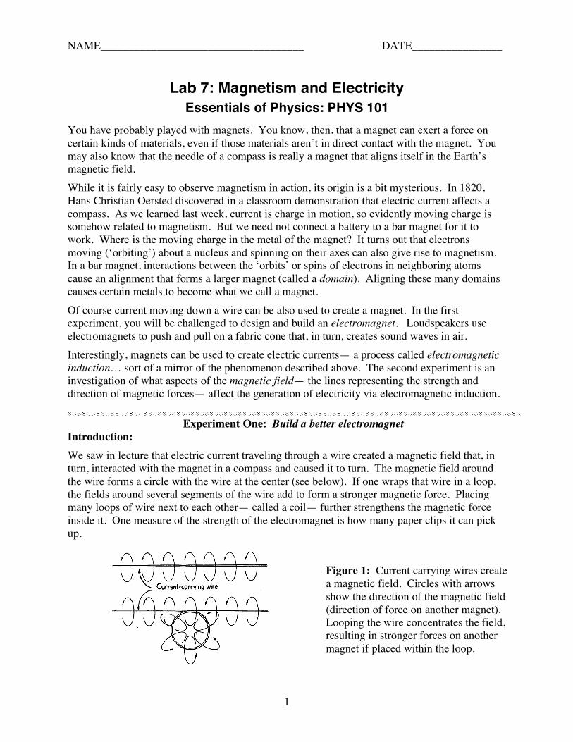
Experiment One: Build a better electromagnet Introduction: We saw in lecture that electric current traveling through a wire created a magnetic field that, in turn, interacted with the magnet in a compass and caused it to turn. The magnetic field around the wire forms a circle with the wire at the center (see below). If one wraps that wire in a loop, the fields around several segments of the wire add to form a stronger magnetic force. Placing many loops of wire next to each other— called a coil— further strengthens the magnetic force inside it. One measure of the strength of the electromagnet is how many paper clips it can pick up.
Figure 1: Current carrying wires create a magnetic field. Circles with arrows show the direction of the magnetic field (direction of force on another magnet). Looping the wire concentrates the field, resulting in stronger forces on another magnet if placed within the loop.

2
Challenge: You are charged with building a better electromagnet. There are several things you can try, listed below: To build a better electromagnet you must rank how effective each modification is at increasing magnetism. Modifications: • Change the number of loops (turns) of wire in the electromagnet. • Change the diameter of the loops of wire. • Put something (pencil, straw, screw?) along the axis of the coil. • Change the current going through the wire. Question: Which do you think will lead to the greatest increase in the number of paper clips an electromagnet can pick up:
1. Doubling the number of loops 2. Doubling the diameter of the loops 3. Placing an iron nail along the axis of the coil 4. Doubling the current traveling through the wire in the electromagnet.
Choose one and give your reasoning below: Checkpoint: Have the lab instructor check your prediction and reasoning, above.
Procedures: Several procedures are listed below, each varying one aspect of the electromagnet. All the procedures are compared to the results using a “reference coil”— comprising 30 loops wound around a small-diameter bolt (with the bolt removed afterwards) connected to one battery.
Reference coil test:
1. Make an electromagnet by winding enameled wire around a small-diameter bolt. Wind 30 complete loops of wire around the core. Leave at least 6” of wire at either end of the coil to allow for connection to the battery.
Figure 2. Increasing the number of turns of a coil (the core will be removed for testing)

3
2. Carefully remove the coil of wire you just made from the core. Place a piece of tape around the coil to keep it from falling apart (see figure, above) (note: try to keep the coil length the same for each experiment, below). Connect the two wires to either end of the empty battery holder.
3. Place the battery in the holder and try to pick up paper clips. This is best accomplished by piling paperclips around and inside the coil (connected to the battery), picking up the coil, and then trying to “stick” extra paper clips to those already stuck. Record how many paper clips you can pick up in all the entries for column 1 in the table, below. As soon as you are done, remove the battery from its holder (to save on batteries).
A) Number of Loops:
1. Wind another, 60 loop coil in the same fashion as step 1), above. Again, carefully remove the coil from the (same) core and connect the wires to the battery holder.
2. Put the battery in the holder and determine how many paper clips can be picked up. Again record the number in column 2 of the data table and disconnect the battery.
B) Diameter of Loops:
1. Make an electromagnet by winding enameled wire around a large-diameter core. Wind 30 complete loops of wire around the small bolt. Again, leave at least 6” of wire at either end of the coil to allow for connection to the battery.
Figure 3: Increasing the diameter of the coil (the cores will be removed before testing).
2. Carefully remove the coil of wire you just made from the core and secure it with tape. Connect the two wires to either end of the empty battery holder.
3. Put the battery in the holder and determine how many paper clips can be picked up using the large diameter coil. Again record the number in the data table and disconnect the battery.
C) Placing an iron core in the coil:
1. Carefully reinsert the small core into the center of the 30-turn, small-diameter coil you wound in the “reference coil” procedure. You may want to carefully remove the tape before doing this.

4
Figure 4: Using an electromagnetic with a core of ferromagnetic material.
2. Connect the two wires to either end of the empty battery holder.
3. Put the battery in the holder and determine how many paper clips can be picked up using the 30-turn, small-diameter coil with the iron bolt, called a “core.” Again record the number in column 2 of the data table and disconnect the battery.
D) Doubling the current through the coil:
1. Connect a second battery holder in series with the first. Place one battery in its holder, but not the second.
Figure 5: Using two batteries in series to push twice as much current through the coil.
2. Connect the two wires of the small, 30-turn coil (without bolt) to either end of the empty battery holder.
3. Put the second battery in the holder and determine how many paper clips can be picked up using the 30-turn, small-diameter coil with double the current. Again record the number in column 2 of the data table and disconnect the battery.
Observations: Data Table: Experiment One
1) # of paper clips 2) # of paper clips 3) ratio of 2) to 1) 4) ranking
Number of turns of coil
for 30-turn coil without core
for 60-turn coil
Diameter of coil
for small 30-turn coil without core.
for larger-diameter 30-turn coil.
Iron core in the coil
for small 30-turn coil without core.
for small 30-turn coil with core
Doubling the current .
for small 30-turn coil without core
30 turn small coil with current doubled

5
Questions:
1. For Procedure D you connected two batteries in series to the coil to double the current. How do you know that connecting two batteries in series doubles the current?
2. For each row of the data table, take the ratio of the entry in the 2nd column to that in the 1st. ratio = 2nd column / 1st column
Enter this ratio in the 3rd column. Why do you take the ratio of the number of paper clips instead of comparing the values? 3. Using the ratios calculated for varying the 4 design criteria, rank the effectiveness of each
variation at increasing the magnetic field strength and record in the 4th column, above. 4. Given limited resources (amount of wire, space to put electromagnet, number of batteries),
describe how you would build the best (strongest) electromagnet below. Draw a picture of your “better electromagnet” and label the important features.
5. What coil configuration served as the “control” during this experiment? Why was it
important to use a “control” in this experiment? Epilogue: The formula which states the relationship between the magnetic field strength and the design of a coil is given by:
B = µNI
l
where B is the strength of the magnetic field, N is the number of turns (loops) for the coil, I is the current, and l is the length of the coil. µ is something called magnetic susceptibility, which is determined by what’s in the coil. Metals such as iron and nickel have very large µ relative to air, and that has the effect of concentrating the magnetic field of the coil in the core. All electromagnets have a magnetic core (iron, nickel, etc.) for this reason.

NAME____________________________________ DATE________________
6
Experiment 2: We’re makin’ electricity here! Introduction: In Experiment 1 you found that passing electric current through a wire arranged as a coil created a magnetic field. A battery was used as a source to push charge through the wire. The moving charges created a magnetic field. What if you were to, instead, connect a light bulb to a coil and use a bar magnet to create the magnetic field. Could you do something with this combination such that charges moved through the light bulb and caused it to light? Question: You have a magnet, a coil and an LED light bulb and current meter connected to the coil as follows:
Figure 6: Coil, current meter, bulb and magnets.
Question 1: What would you do with the magnet to “generate” electric current? (actually, electrical energy is not generated, but converted from another type of energy.) Please be specific in describing what you would do. Checkpoint: Have the lab instructor check your answer before proceeding with the experiment. For this experiment you will explore how varying the interaction of the magnet with the coil causes changes in how electricity (current) is generated.
Part A: Procedure:
1. Pick up the magnet and experiment with the coil and magnet combination.

7
2. What do you need to do with the magnet to light the LED light? Observe the deflection of the meter indicating the amount of current through the circuit. Record your observations below.
Observations:
Calculations/Questions: 1. What, specifically, did you have to do in order to light the bulb? How does this compare to
what you had predicted in answering the question, above? 2. State a rule about what, in general, must be done with the magnet to generate electricity.
Give supporting evidence.
Part B: Prediction: Where is the best place to move the magnet in relation to the coil so as to produce the maximum current? Describe what orientation of the magnet relative to the coil you think will work best. (draw a figure if that helps.) Part B: Procedure:
1. Move the magnet along different paths outside the coil and inside the coil while observing the brightness of the bulb and the deflection of the current meter needle.
2. Try to move the magnet at approximately the same speed each time. Record your observations of amount of light and current meter movement below.

8
Observations:
Calculations/Questions: 1. Which path and orientation, specifically, produced the best results (brightest bulb flash,
greatest current meter deflection)? Draw a magnet near the coil, below, showing the best orientation of the magnet. Describe in words the optimal orientation of the magnet.
2. Draw on the diagram (previous page) an arrow showing the optimal path of the moving
magnet. Did your observations from Experiment One (building an electromagnet) give you any guidance in determining the optimal path? How?
3. Is there a path or orientation of the magnet where no current is observed to be generated? If
so, describe the path or orientation. 4. Restate your rule, above, to include the information gleaned from this part of Experiment 2.
Again, give supporting evidence.
9
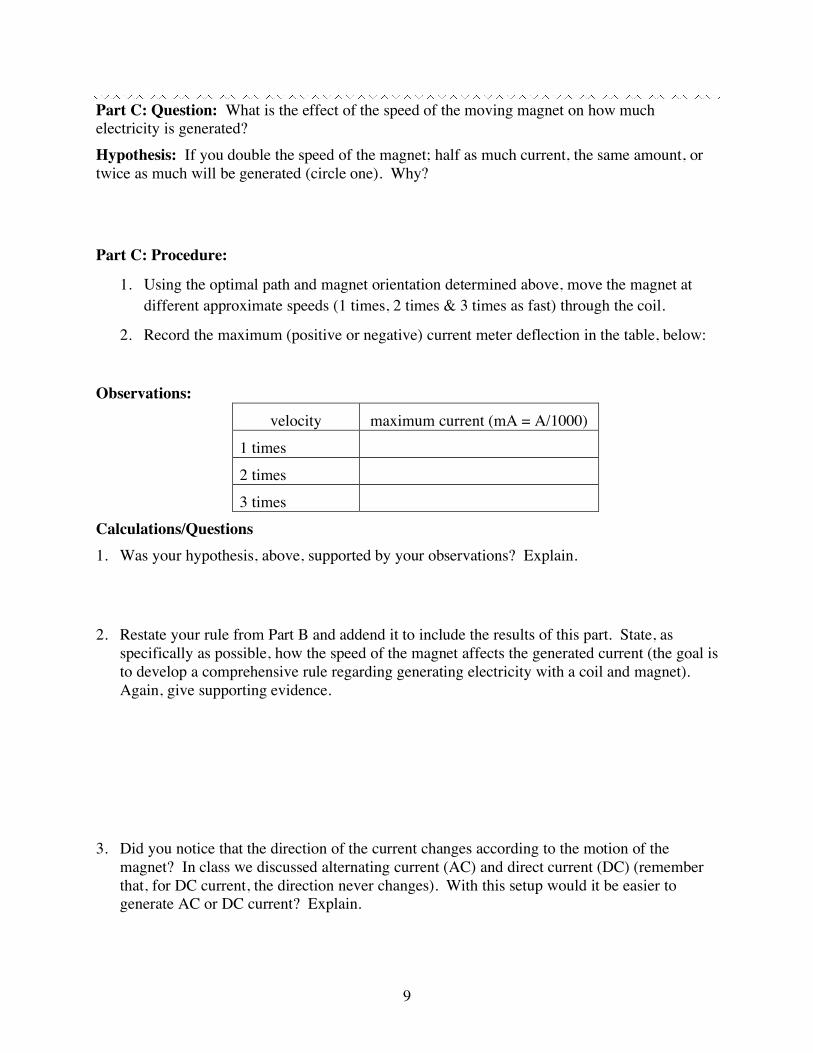
Part C: Question: What is the effect of the speed of the moving magnet on how much electricity is generated? Hypothesis: If you double the speed of the magnet; half as much current, the same amount, or twice as much will be generated (circle one). Why?
Part C: Procedure:
1. Using the optimal path and magnet orientation determined above, move the magnet at different approximate speeds (1 times, 2 times & 3 times as fast) through the coil.
2. Record the maximum (positive or negative) current meter deflection in the table, below:
Observations:
velocity maximum current (mA = A/1000)
1 times
2 times
3 times
Calculations/Questions 1. Was your hypothesis, above, supported by your observations? Explain. 2. Restate your rule from Part B and addend it to include the results of this part. State, as
specifically as possible, how the speed of the magnet affects the generated current (the goal is to develop a comprehensive rule regarding generating electricity with a coil and magnet). Again, give supporting evidence.
3. Did you notice that the direction of the current changes according to the motion of the
magnet? In class we discussed alternating current (AC) and direct current (DC) (remember that, for DC current, the direction never changes). With this setup would it be easier to generate AC or DC current? Explain.

10
(These questions can be answered after lab) 4. Almost the same set of rules that govern the strength of an electromagnet (number of loops in
coil, diameter of coil) also govern how much electricity is generated by a coil. With the electromagnet, however, we found that increasing the current in the coil increased the strength of the electromagnet. Similarly, increasing how quickly the magnetic field changes, when used to generate electricity, increases amount of current that is generated. Describe, below, what factors you would consider in designing a magnet & coil electrical generating device.
5. When a magnet moves through a coil, what type of energy is being converted to electrical
energy with our magnet and coil system? Explain. Definitions: Name Symbol Definition Formula Magnetic field strength
B (Teslas) The strength of a magnet and the direction of the force at different locations around a magnet.
Magnetic flux Φ (Teslas/m2) The strength of a magnetic field over a given area.
Φ = B / area
Current I (Amps) Charges in motion. The number of charges (Q) passing a point in one second.
I = Q/t
Magnetic field strength inside a coil
B (Teslas) The magnetic field inside a coil is proportional to the number of turns per length (N/l), the current through the coil (I0, and the magnetic susceptability (µ)
B = µ · N · I / l
Magnetic Susceptibility
T · m / A A property of matter (air, metals, etc.) that has the effect of “concentrating” magnetic fields.
Faraday’s Law of Electromagnetic Induction
ε (Volts) ε is the “charge push” induced in a loop of wire when a magnetic field is changing within it. For a coil, ε is proportional to N and the change in magnetic flux (ΔΦ) over time.
ε = -N ΔΦ / Δt

11