Embed Size (px)
Citation preview

© 2012 Pica8 Inc. All © 2012 Pica8 Inc. All
© 2012 Pica8 Inc. All Rights Reserved. P a g e | 1
Configuration Guide
PICA8, INC.
L2/L3 Configuration Guide PicOS 2.1.0
Yachal Chen, Zoneson Chen
2013-11-22
This guide provides the configuration commands of L2/L3 for PicOS 2.1.0.

© Copyright 2009- 2013 Pica8, Inc. All rights reserved. Pica8, Inc. makes no warranty of any kind with regard to this material, including, but not limited to, the implied warranties of merchantability and fitness for a particular purpose. The information is provided “as is” without warranty of any kind, and is subject to change without notice.
L2/L3 Configuration Guide, PicOS 2.1.0.

© 2012 Pica8 Inc. All
Table of Contents
© 2012 Pica8 Inc. All
© 2013 Pica8 Inc. All Rights Reserved. L2/L3 Configuration Guide
P a g e | 3
Table of Contents
TABLE OF CONTENTS ............................................................................................................ 3
PREFACE .................................................................................................................................. 6 Intended Audience ................................................................................................................................................................6 PicOS Documents .................................................................................................................................................................6 Organization .........................................................................................................................................................................6
CHAPTER 1. OVERVIEW ......................................................................................................... 7 L2/L3Features List ................................................................................................................................................................7
CHAPTER 2.SYSTEM MANAGEMENT CONFIGURATION ..................................................... 9 The Boot Process ..................................................................................................................................................................9 Operation Mode and Configuration Mode .......................................................................................................................... 11 Commit Failed and Exit Discard......................................................................................................................................... 11 Configuring DHCP and a Static IP Address ....................................................................................................................... 12 Configuring DHCP relay .................................................................................................................................................... 12 Configuring DHCP option82 .............................................................................................................................................. 13 Configuring DHCP snooping .............................................................................................................................................. 13 Configuring a User Account ............................................................................................................................................... 14 ConfiguringAAA (Authentication/Authorization/Accounting) ...................................................................................... 1514 ConfiguringSSH and Telnet Parameters ............................................................................................................................. 17 Configuring the Log-inACL ........................................................................................................................................... 1817 ConfiguringNTP and the Timezone Parameter ............................................................................................................... 1817 Configuring IPFIX .............................................................................................................................................................. 18 ConfiguringsFlow ........................................................................................................................................................... 1918 Configuring SNMP ......................................................................................................................................................... 2120 Configuring theSyslog Log Level ................................................................................................................................... 2221 Configuring theSyslog Disk ............................................................................................................................................ 2322 Updating the PicOS Software and Platform ....................................................................................................................... 23 DisplayingSystem Information ....................................................................................................................................... 2423 Technical Support ........................................................................................................................................................... 2625 Flushing ARP and the Neighbor Table ............................................................................................................................... 26 Rebooting the System ......................................................................................................................................................... 26 Displaying the Debugging Message ............................................................................................................................... 2726 Installing Software .............................................................................................................................................................. 27
CHAPTER 3.FILE MANAGEMENT CONFIGURATION .......................................................... 30 Managing ConfigurationFiles ............................................................................................................................................. 30 Displaying Your Current Configuration ............................................................................................................................. 32 Saving your Current Configuration as the Default Configuration ...................................................................................... 33 Rolling Back a Configuration ............................................................................................................................................. 33 ManagingConfiguration Files ............................................................................................................................................. 34 Saving, Applying, Executing and Loading Configuration Files ......................................................................................... 35

© 2012 Pica8 Inc. All © 2012 Pica8 Inc. All
Table of Contents
© 2013 Pica8 Inc. All Rights Reserved. L2/L3 Configuration Guide
P a g e | 4
CHAPTER 4.LAYER2 SWITCHING CONFIGURATION ......................................................... 37 Configuring LLDP (Link Layer Discovery Protocol) ......................................................................................................... 37 Static Link Aggregation Configuration .............................................................................................................................. 38 Link Aggregation Control Protocol (LACP) Configuration ............................................................................................... 39 MLAG Configuration Guide .............................................................................................................................................. 40 Configuring base mLAG example ...................................................................................................................................... 42 Ethernet Port Configuration ................................................................................................................................................ 47 Storm Control in Ethernet Port Configuration .................................................................................................................... 49 Static MAC entries and Dynamic MAC Address Learning ................................................................................................ 49 Cut-through Mode Configuration ....................................................................................................................................... 50 Configuring Mirroring ........................................................................................................................................................ 50 802.1Q Basic Port Configuration ........................................................................................................................................ 50 VLAN Configuration Example ........................................................................................................................................... 52 Q-in-Q Basic Port Configuration ........................................................................................................................................ 54 Q-in-Q Configuration Example .......................................................................................................................................... 57 MSTP Configuration .......................................................................................................................................................... 63 PVST Configuration ........................................................................................................................................................... 66 MSTP Configuration Example ........................................................................................................................................... 69 PVST Configuration Example ............................................................................................................................................ 84 Buffer Management Configuration ..................................................................................................................................... 88 BPDU Tunneling Configuration ......................................................................................................................................... 89 BPDU Tunneling ConfigurationExample ........................................................................................................................... 90 Configuring Flex Links ....................................................................................................................................................... 92 UDLD Protocol Configuration ........................................................................................................................................... 93 Configuring IPv6 RA Guard ............................................................................................................................................... 94
CHAPTER 5. LAYER3 ROUTING CONFIGURATION ............................................................ 97 Layer3 VLAN Interface Configuration .............................................................................................................................. 97 ARP Configuration ............................................................................................................................................................. 98 Dynamic ARP Inspection---DAI ........................................................................................................................................ 98 Static Routing Configuration ............................................................................................................................................ 100 Static Routing Configuration Example ............................................................................................................................. 101 RIPv2 Routing Protocol Configuration ............................................................................................................................ 104 RIPv2 Routing Configuration Example ............................................................................................................................ 106 OSPF Routing Protocol Configuration ............................................................................................................................. 109 OSPF Routing Basic Configuration Example ................................................................................................................... 110 OSPF Configuration Example: NSSA/Stub/Normal ........................................................................................................ 114 OSPF Stub Area/NSSA Summary .................................................................................................................................... 117 OSPF Virtual Link Configuration Guide .......................................................................................................................... 118 OSPF Area RangeConfiguration Guide ............................................................................................................................ 122 Importing anExternal Route into an OSPF Area .............................................................................................................. 124 BFD Protocol Configuration ............................................................................................................................................. 126 BFD Basic Configuration Example .................................................................................................................................. 128 BGP Configuration Guide ................................................................................................................................................ 131 BGP Basic Configuration Example .................................................................................................................................. 137 BGP Route Reflector ConfigurationExample ................................................................................................................... 144 BGP ConfederationConfiguration Example ..................................................................................................................... 149 BGP Load Balancing Configuration Example .................................................................................................................. 155 Configuring ECMP (Equal-CostMultipathRouting) ......................................................................................................... 162 Configuring VRRP (Virtual Router Redundancy Protocol) ............................................................................................. 164 IPv6 Neighbor Configuration ........................................................................................................................................... 165 IPv6 Static Routing Configuration.................................................................................................................................... 165

© 2012 Pica8 Inc. All © 2012 Pica8 Inc. All
Table of Contents
© 2013 Pica8 Inc. All Rights Reserved. L2/L3 Configuration Guide
P a g e | 5
OSPFv3 Routing Protocol Configuration ......................................................................................................................... 166 ACLand Filter Configuration ............................................................................................................................................ 168
CHAPTER 6. MULTICAST CONFIGURATION ..................................................................... 171 IGMP Snooping Configuration ......................................................................................................................................... 171 IGMP Configuration ......................................................................................................................................................... 172 PIM-SM Configuration ..................................................................................................................................................... 173 PIM-SM Configuration Example ...................................................................................................................................... 175
CHAPTER 7.QOS CONFIGURATION .................................................................................. 179 Configuring QoS ............................................................................................................................................................... 179
CHAPTER 8.OPENFLOW CONFIGURATION ...................................................................... 181 OpenFlowIntroduction ...................................................................................................................................................... 181 OpenFlowBasic Configuration ......................................................................................................................................... 184 Group table Configuration ................................................................................................................................................ 188 Crossflow Configuration Example ................................................................................................................................... 191
© 2012 Pica8 Inc. All
Preface
© 2012 Pica8 Inc. All
© 2013 Pica8 Inc. All Rights Reserved. L2/L3 Configuration Guide
P a g e | 6
Preface
Intended Audience This guide is intended for data center administrators, system administrators, and customer service staffs responsible for monitoring or configuring PicOS L2/L3.
PicOS Documents The PicOS documents are available on our Pica8 website: http://www.pica8.com/portal/
Organization This configuration guide is organized as follows:
Chapter Description
Chap 1. Overview Provides an overview of the L2/L3 switch
Chap 2. System Management Configuration Describes system management configurations
Chap 3. File Management Configuration Describes file management configurations
Chap 4. Layer 2 Switching Configuration Describes Layer2 switching configuration steps
Chap 5. Layer 2 Switching Configuration Describes Layer 3 routing configuration steps
Chap 6. Multicast Configuration Describesmulticast configuration steps
Chap 7. QoS Configuration Describes QoS configuration steps
Chap 8. OpenFlow Configuration Describes OpenFlowconfiguration steps

© 2012 Pica8 Inc. All
Overview
© 2012 Pica8 Inc. All
© 2013 Pica8 Inc. All Rights Reserved. Configuration Guide
P a g e | 7
Chapter 1. Overview
This chapter provides an overview of PicOS L2/L3 features, including Layer2 switching and Layer3 routing.
L2/L3Features List
PicOS L2/L3 supports Layer2 switching (STP, RSTP, MSTP, MAC learning, Q-in-Q) and Layer3 routing (static routing, RIPv2, OSPF, IGMP, PIM-SM, IPv6):
Table 1-1. L2/L3 Features List.
Category Functional Requirement
System Management&
Administration
Support for clock/date setting and NTP
Support for inband IP access via any routed interface
Support for DHCP client ,DHCP relay ,DHCP Option 82 and DHCP snooping
Support for multiple local user accounts
Support for SSHv2 protocol
Ability to enable debugging for a specific module
Support for Read Only and Read Write access SNMP
Support for IPFIX, monitors data flow in specified server
Device Configuration, Software,& File Management
Device configuration can be saved to flash on the device
Support for configuration versioning and rollback; compares the two configurations for differences
Ability to import/export configuration files, device software, and logs from a file on a remote server
(tftp/scp as possible options)
Ping tool and Traceroute tool from CLI
SSH tool and telnet tool from CLI
Ability to view and configure MAC/ARP table information
Layer2 Forwarding and Protocol
Support for LLDP protocols for detecting devices on a link
Support for LACP protocol andhashing of traffic using Src/Dst MAC address, Src/Dst IP address, and Layer4 port information and mlag
Support for 802.1q trunked interfaces, for both single and LAG interfaces
Support for 802.1q tagged/untagged interfaces and native tags
Support for Q-in-Q
Support for Jumbo Frame
Support for 802.1d Spanning Tree Protocol (STP)
Support for 802.1w rapid STP (RSTP)and Per-VLAN Spanning Tree(PVST)
Support for 802.1s Multiple Spanning Tree protocol (MSTP)
Support for functionality of BPDU Guard / Filter/UDLD etc.
Support for storm-control for unicast, multicast, broadcast
Support foringress/egress port mirroring

© 2012 Pica8 Inc. All © 2012 Pica8 Inc. All
Overview
© 2013 Pica8 Inc. All Rights Reserved. L2/L3 Configuration Guide
P a g e | 8
Support for802.1p in Layer2 forwarding
Support for Flow control per-interface
Supportfor IGMP snooping enable per-VLAN
Support for IGMP snooping querier per-VLAN
Layer3 Forwarding and Routing
Protocol Full support for dual stacked IPv4 and IPv6 addressing.
Support for 6 members in a Layer3 LAG interface
Support for IPv4 and IPv6 static route configuration
Support for OSPFv2 (IPv4)
Support for stub, normal, and NSSA OSPF area types
Support for up to 32 equal-cost routes in OSPF
Support for RIP routing protocol
Support for BGP routing protocol and BFD
Support for 128 equal-cost routes in the device’s routing/forwarding tables
Support for ECMP routing with hashing of traffic using Src/Dst IP and Port
Support the ToS and DSCP in Layer3 forwarding
Support for IGMP v1/v2
Support for PIM-SM multicast routing
Support for VRRP protocol

System Management Configuration
© 2012 Pica8 Inc. All © 2012 Pica8 Inc. All
© 2013 Pica8 Inc. All Rights Reserved. Configuration Guide
P a g e | 9
Chapter 2.System Management Configuration
Overview This chapter describes the configuration steps for the system management, DHCP, and setting up a user account.
The Boot Process
Before receiving the switch’s boot information, you should make sure the switch has been connected in the console port with the correct baud rate, data bits value, and stop bits value.
●The baud rate is 115200. ● The data bits value is 8. ● The stop bits value is 1.
The output message of the boot-up is shown below: U-Boot 1.3.0 (Mar 8 2011 - 16:39:03)
CPU: 8541, Version: 1.1, (0x80720011)
Core: E500, Version: 2.0, (0x80200020)
Clock Configuration:
CPU: 825 MHz, CCB: 330 MHz,
DDR: 165 MHz, LBC: 41 MHz
L1: D-cache 32 kB enabled
I-cache 32 kB enabled
I2C: ready
DRAM: Initializing
initdram robin1
initdram robin2
robin before CFG_READ_SPD
robin after CFG_READ_SPD
initdram robin3
DDR: 512 MB
FLASH: 32 MB
L2 cache 256KB: enabled
In: serial
Out: serial
Err: serial
Net: TSEC0, TSEC1
IDE: Bus 0: OK
Device 0: Model: CF 512MB Firm: 20060911 Ser#: TSS25016070309051750
Type: Hard Disk
Capacity: 495.1 MB = 0.4 GB (1014048 x 512)
Hit any key to stop autoboot: 5
Note: You can modify the baud rate of the switch. For that, enter the U-Boot and configure the baud rate (or other parameters). Eaxmple:
U-Boot 1.3.0 (Sep 8 2010 - 17:20:00)
CPU: 8541, Version: 1.1, (0x80720011)
Core: E500, Version: 2.0, (0x80200020)
© 2012 Pica8 Inc. All © 2012 Pica8 Inc. All
System Management Configuration
© 2013 Pica8 Inc. All Rights Reserved. L2/L3 Configuration Guide
P a g e | 10
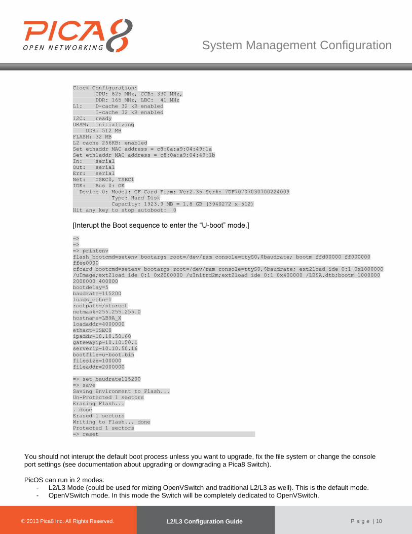
Clock Configuration:
CPU: 825 MHz, CCB: 330 MHz,
DDR: 165 MHz, LBC: 41 MHz
L1: D-cache 32 kB enabled
I-cache 32 kB enabled
I2C: ready
DRAM: Initializing
DDR: 512 MB
FLASH: 32 MB
L2 cache 256KB: enabled
Set ethaddr MAC address = c8:0a:a9:04:49:1a
Set eth1addr MAC address = c8:0a:a9:04:49:1b
In: serial
Out: serial
Err: serial
Net: TSEC0, TSEC1
IDE: Bus 0: OK
Device 0: Model: CF Card Firm: Ver2.35 Ser#: 7DF70707030700224009
Type: Hard Disk
Capacity: 1923.9 MB = 1.8 GB (3940272 x 512)
Hit any key to stop autoboot: 0
[Interupt the Boot sequence to enter the “U-boot” mode.]
=>
=>
=> printenv
flash_bootcmd=setenv bootargs root=/dev/ram console=ttyS0,$baudrate; bootm ffd00000 ff000000
ffee0000
cfcard_bootcmd=setenv bootargs root=/dev/ram console=ttyS0,$baudrate; ext2load ide 0:1 0x1000000
/uImage;ext2load ide 0:1 0x2000000 /uInitrd2m;ext2load ide 0:1 0x400000 /LB9A.dtb;bootm 1000000
2000000 400000
bootdelay=5
baudrate=115200
loads_echo=1
rootpath=/nfsroot
netmask=255.255.255.0
hostname=LB9A_X
loadaddr=4000000
ethact=TSEC0
ipaddr=10.10.50.60
gatewayip=10.10.50.1
serverip=10.10.50.16
bootfile=u-boot.bin
filesize=100000
fileaddr=2000000
=> set baudrate115200
=> save
Saving Environment to Flash...
Un-Protected 1 sectors
Erasing Flash...
. done
Erased 1 sectors
Writing to Flash... done
Protected 1 sectors
=> reset
You should not interupt the default boot process unless you want to upgrade, fix the file system or change the console port settings (see documentation about upgrading or downgrading a Pica8 Switch). PicOS can run in 2 modes:
- L2/L3 Mode (could be used for mizing OpenVSwitch and traditional L2/L3 as well). This is the default mode. - OpenVSwitch mode. In this mode the Switch will be completely dedicated to OpenVSwitch.
© 2012 Pica8 Inc. All © 2012 Pica8 Inc. All
System Management Configuration
© 2013 Pica8 Inc. All Rights Reserved. L2/L3 Configuration Guide
P a g e | 11
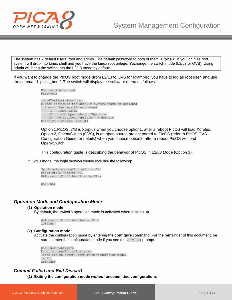
The system has 2 default users: root and admin. The default password to both of them is “pica8”. If you login as root, system will drop into Linux shell and you have the Linux root prilege. Yochange the switch mode (L2/L3 or OVS). Using admin will bring the switch into the L2/L3 mode by default.
If you want to change the PicOS boot mode (from L2/L3 to OVS for example), you have to log as root user and use the command “picos_boot”. The switch will display the software menu as follows:
XorPlus login: root
Password:
root@XorPlus#picos_boot
Please configure the default system start-up options:
(Press other key if no change)
[1] PicOS L2/L3
[2] PicOS Open vSwitch/OpenFlow
[3] No start-up options * default
Enter your choice (1,2,3):
Option 1,PicOS l2/l3 is Xorplus.when you choose option1, after a reboot PicOS will load Xorplus. Option 2, OpenvSwitch (OVS), is an open source project ported to PicOS (refer to PicOS OVS Configuration Guide for details) when you choose option2, after a reboot PicOS will load OpenvSwitch. This configuration guide is describing the behavior of PicOS in L2/L3 Mode (Option 1).
In L2/L3 mode, the login session should look like the following:
Synchronizing configuration...OK.
Pica8 PicOS Version 2.1
Welcome to PicOS L2/L3 on XorPlus
XorPlus>
Operation Mode and Configuration Mode
(1) Operation mode By default, the switch’s operation mode is activated when it starts up.
Welcome to PicOS L2/L3on XorPlus
XorPlus>
(2) Configuration mode Activate the configuration mode by entering the configure command. For the remainder of this document, be
sure to enter the configuration mode if you see the XorPlus# prompt.
XorPlus> configure
Entering configuration mode.
There are no other users in configuration mode.
[edit]
XorPlus#
Commit Failed and Exit Discard
(1) Exiting the configuration mode without uncommitted configurations

© 2012 Pica8 Inc. All © 2012 Pica8 Inc. All
System Management Configuration
© 2013 Pica8 Inc. All Rights Reserved. L2/L3 Configuration Guide
P a g e | 12
Switch to the execution mode from the configuration mode without any uncommitted configurations.
XorPlus# exit
XorPlus>
(2) Exiting the configuration mode with uncommitted configurations Use the exit discard command to enter the execution mode from the configuration mode with any uncommitted or failed committed configurations.
XorPlus# set interface gigabit-ethernet ge-1/1/1 disable true
[edit]
XorPlus# exit
ERROR: There are uncommitted changes.
Use "commit" to commit the changes, or "exit discard" to discard them.
XorPlus# exit discard
XorPlus>
Configuring DHCP and a Static IP Address
(1) Enabling DHCP By default, DHCP is enabled on the management interface eth0. You can enable DHCP manually with the following CLI command: XorPlus# set interface management-ethernet eth0 address dhcp
[edit]
XorPlus# commit
Commit OK.
Save done.
[edit]
XorPlus#
(2) Configuring a static IP address and gateway Configure yourmanagement interface eth0 witha static IP address. XorPlus# set interface management-ethernet eth0 address 192.168.1.5/24
[edit]
XorPlus# set interface management-ethernet eth0 gateway 192.168.1.1
[edit]
XorPlus# commit
Commit OK.
Save done.
[edit]
XorPlus#
Configuring DHCP relay
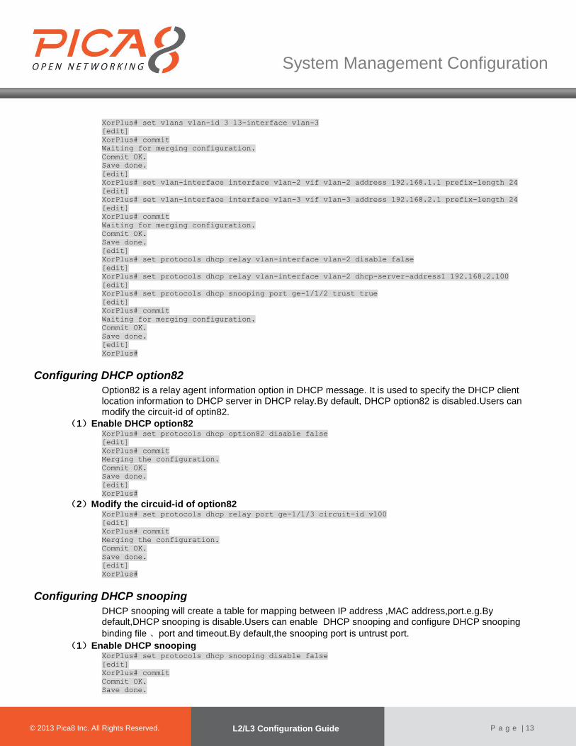
(1) Enabling DHCP relay in a VLAN interface When you enable DHCP relay in a VLAN interface, the switch will relay the received DHCP request to the specified DHCP server via routing. Usually, the port connects to DHCP server should be a trusted port .So ,users should configure this port trust true. XorPlus# set vlans vlan-id 2
[edit]
XorPlus# set vlans vlan-id 3
[edit]
XorPlus# set interface gigabit-ethernet ge-1/1/1 family ethernet-switching native-vlan-id 2
[edit]
XorPlus# set interface gigabit-ethernet ge-1/1/2 family ethernet-switching native-vlan-id 3
[edit]
XorPlus# set vlans vlan-id 2 l3-interface vlan-2
[edit]
© 2012 Pica8 Inc. All © 2012 Pica8 Inc. All
System Management Configuration
© 2013 Pica8 Inc. All Rights Reserved. L2/L3 Configuration Guide
P a g e | 13
XorPlus# set vlans vlan-id 3 l3-interface vlan-3
[edit]
XorPlus# commit
Waiting for merging configuration.
Commit OK.
Save done.
[edit]
XorPlus# set vlan-interface interface vlan-2 vif vlan-2 address 192.168.1.1 prefix-length 24
[edit]
XorPlus# set vlan-interface interface vlan-3 vif vlan-3 address 192.168.2.1 prefix-length 24
[edit]
XorPlus# commit
Waiting for merging configuration.
Commit OK.
Save done.
[edit]
XorPlus# set protocols dhcp relay vlan-interface vlan-2 disable false
[edit]
XorPlus# set protocols dhcp relay vlan-interface vlan-2 dhcp-server-address1 192.168.2.100
[edit]
XorPlus# set protocols dhcp snooping port ge-1/1/2 trust true
[edit]
XorPlus# commit
Waiting for merging configuration.
Commit OK.
Save done.
[edit]
XorPlus#
Configuring DHCP option82
Option82 is a relay agent information option in DHCP message. It is used to specify the DHCP client location information to DHCP server in DHCP relay.By default, DHCP option82 is disabled.Users can modify the circuit-id of optin82.
(1)Enable DHCP option82 XorPlus# set protocols dhcp option82 disable false
[edit]
XorPlus# commit
Merging the configuration.
Commit OK.
Save done.
[edit]
XorPlus#
(2)Modify the circuid-id of option82 XorPlus# set protocols dhcp relay port ge-1/1/3 circuit-id v100
[edit]
XorPlus# commit
Merging the configuration.
Commit OK.
Save done.
[edit]
XorPlus#
Configuring DHCP snooping
DHCP snooping will create a table for mapping between IP address ,MAC address,port.e.g.By default,DHCP snooping is disable.Users can enable DHCP snooping and configure DHCP snooping
binding file 、port and timeout.By default,the snooping port is untrust port.
(1)Enable DHCP snooping XorPlus# set protocols dhcp snooping disable false
[edit]
XorPlus# commit
Commit OK.
Save done.
© 2012 Pica8 Inc. All © 2012 Pica8 Inc. All
System Management Configuration
© 2013 Pica8 Inc. All Rights Reserved. L2/L3 Configuration Guide
P a g e | 14
[edit]
XorPlus#
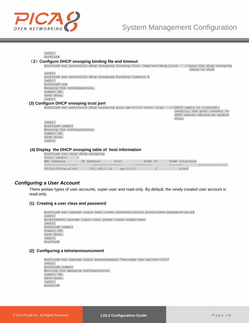
(2)Configure DHCP snooping binding file and timeout XorPlus# set protocols dhcp snooping binding file /tmp/run/dhcp_bind //sync the dhcp snooping
table to disk
[edit]
XorPlus# set protocols dhcp snooping binding timeout 8
[edit]
XorPlus# com
Merging the configuration.
Commit OK.
Save done.
[edit]
(3) Configure DHCP snooping trust port XorPlus# set protocols dhcp snooping port ge-1/1/2 trust true //(DHCP reply is trusted),
usually, the port connect to
DHCP server should be enable
this.
[edit]
XorPlus# commit
Merging the configuration.
Commit OK.
Save done.
[edit]
(4) Display the DHCP snooping table of host information XorPlus# run show dhcp snooping
Total count: 1
MAC Address IP Address Port VLAN ID VLAN Interface
----------------- --------------- --------- ------- ---------------
00:1d:09:fa:a1:b4 192.168.1.10 ge-1/1/1 2 vlan2
Configuring a User Account
There aretwo types of user accounts, super-user and read-only. By default, the newly created user account is read-only.
(1) Creating a user class and password
XorPlus# set system login user ychen authentication plain-text-password pica8
[edit]
XorPlus#set system login user ychen class super-user
[edit]
XorPlus# commit
Commit OK.
Save done.
[edit]
XorPlus#
(2) Configuring a telnetannouncement
XorPlus# set system login announcement "welcome the switch-1101"
[edit]
XorPlus# commit
Waiting for merging configuration.
Commit OK.
Save done.
[edit]
XorPlus#
© 2012 Pica8 Inc. All © 2012 Pica8 Inc. All
System Management Configuration
© 2013 Pica8 Inc. All Rights Reserved. L2/L3 Configuration Guide
P a g e | 15
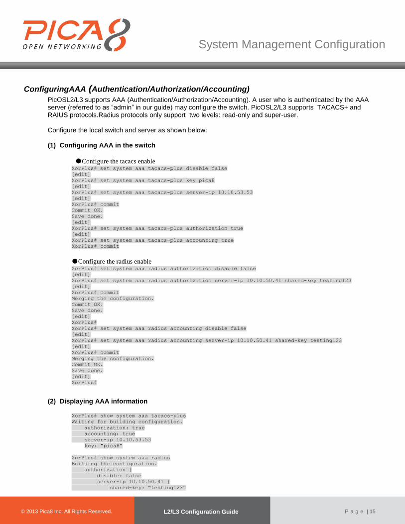
ConfiguringAAA (Authentication/Authorization/Accounting)
PicOSL2/L3 supports AAA (Authentication/Authorization/Accounting). A user who is authenticated by the AAA server (referred to as “admin” in our guide) may configure the switch. PicOSL2/L3 supports TACACS+ and RAIUS protocols.Radius protocols only support two levels: read-only and super-user.
Configure the local switch and server as shown below: (1) Configuring AAA in the switch
●Configure the tacacs enable XorPlus# set system aaa tacacs-plus disable false
[edit]
XorPlus# set system aaa tacacs-plus key pica8
[edit]
XorPlus# set system aaa tacacs-plus server-ip 10.10.53.53
[edit]
XorPlus# commit
Commit OK.
Save done.
[edit]
XorPlus# set system aaa tacacs-plus authorization true
[edit]
XorPlus# set system aaa tacacs-plus accounting true
XorPlus# commit
●Configure the radius enable XorPlus# set system aaa radius authorization disable false
[edit]
XorPlus# set system aaa radius authorization server-ip 10.10.50.41 shared-key testing123
[edit]
XorPlus# commit
Merging the configuration.
Commit OK.
Save done.
[edit]
XorPlus#
XorPlus# set system aaa radius accounting disable false
[edit]
XorPlus# set system aaa radius accounting server-ip 10.10.50.41 shared-key testing123
[edit]
XorPlus# commit
Merging the configuration.
Commit OK.
Save done.
[edit]
XorPlus#
(2) Displaying AAA information
XorPlus# show system aaa tacacs-plus
Waiting for building configuration.
authorization: true
accounting: true
server-ip 10.10.53.53
key: "pica8"
XorPlus# show system aaa radius
Building the configuration.
authorization {
disable: false
server-ip 10.10.50.41 {
shared-key: "testing123"

© 2012 Pica8 Inc. All © 2012 Pica8 Inc. All
System Management Configuration
© 2013 Pica8 Inc. All Rights Reserved. L2/L3 Configuration Guide
P a g e | 16
}
}
accounting {
disable: false
server-ip 10.10.50.41 {
shared-key: "testing123"
}
}
[edit]
XorPlus#
(3) Configuring the AAA server
Configure the AAA server configurationfile as follows: Tacacs server configuration:
key = pica8
# Accounting File
accounting file = /var/tmp/acctfile
default authentication = file /etc/passwd
user = admin {
member = admins
}
group = admins {
global = cleartext "password"
service = exec {
default attribute = permit
}
}
user = operator {
global = cleartext "operator"
service = exec {
default attribute = permit
}
}
user = ychen {
global = cleartext "ychen"
member = admins
service = exec {
default attribute = permit
}
}
Users should add “/usr/share/freeradius/dictionary.pica8” to radius server before the configuration. Radius server configuration:
operator Cleartext-Password := "testing"
Service-Type = Framed-User,
Framed-Protocol = PPP,
Framed-IP-Address = 172.16.3.33,
Framed-IP-Netmask = 255.255.255.0,
Framed-Routing = Broadcast-Listen,
Framed-Filter-Id = "std.ppp",
Framed-MTU = 1500,
Framed-Compression = Van-Jacobsen-TCP-IP,
Class = "read-only"
ychen Cleartext-Password := "testing"
Service-Type = Framed-User,
Framed-Protocol = PPP,
Framed-IP-Address = 172.16.3.33,
Framed-IP-Netmask = 255.255.255.0,
Framed-Routing = Broadcast-Listen,
Framed-Filter-Id = "std.ppp",

© 2012 Pica8 Inc. All © 2012 Pica8 Inc. All
System Management Configuration
© 2013 Pica8 Inc. All Rights Reserved. L2/L3 Configuration Guide
P a g e | 17
Framed-MTU = 1500,
Framed-Compression = Van-Jacobsen-TCP-IP,
Class = "super-user"
Following theconfiguration above, the admin or operator can access the switch viatelnet or SSH. Any validCLI commands executed by the admin or operator will be recordedto the specified accounting
file. In our example above,the accounting file is/var/tmp/acctfile.
(4) Configuring the local log-in
XorPlus# set system aaa local disable true
[edit]
XorPlus# commit
Commit OK.
Save done.
[edit]
In theconfiguration above, you cannot log in to the switch with a local account.
ConfiguringSSH and Telnet Parameters
(1) Configuring the SSH connection limit
XorPlus# set system services ssh protocol-version v2
[edit]
XorPlus# set system services ssh connection-limit 5
[edit]
XorPlus# commit
Waiting for merging configuration.
Commit OK.
Save done.
[edit]
XorPlus#
(2) Disablingtelnet service
XorPlus# set system services telnet disable true
[edit]
XorPlus# commit
Waiting for merging configuration.
Commit OK.
Save done.
[edit]
XorPlus#
(3) Enabling and disabling inband service
By default, SSH and telnet with inband interfacesare disabled. You can enableinband service by entering the command below: XorPlus# set system inband enable true
[edit]
XorPlus# commit
Waiting for merging configuration.
Commit OK.
Save done.
[edit]
XorPlus#
© 2012 Pica8 Inc. All © 2012 Pica8 Inc. All
System Management Configuration
© 2013 Pica8 Inc. All Rights Reserved. L2/L3 Configuration Guide
P a g e | 18
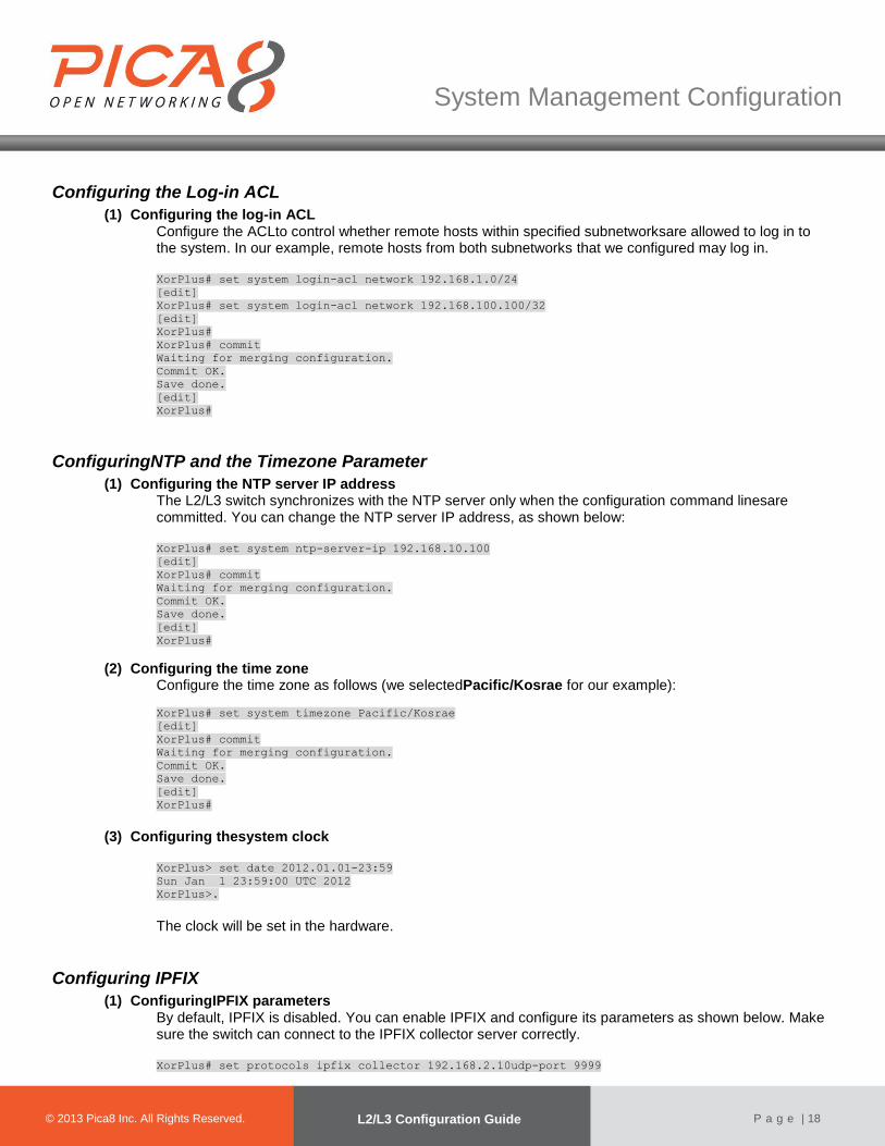
Configuring the Log-in ACL
(1) Configuring the log-in ACL Configure the ACLto control whether remote hosts within specified subnetworksare allowed to log in to the system. In our example, remote hosts from both subnetworks that we configured may log in. XorPlus# set system login-acl network 192.168.1.0/24
[edit]
XorPlus# set system login-acl network 192.168.100.100/32
[edit]
XorPlus#
XorPlus# commit
Waiting for merging configuration.
Commit OK.
Save done.
[edit]
XorPlus#
ConfiguringNTP and the Timezone Parameter
(1) Configuring the NTP server IP address The L2/L3 switch synchronizes with the NTP server only when the configuration command linesare committed. You can change the NTP server IP address, as shown below: XorPlus# set system ntp-server-ip 192.168.10.100
[edit]
XorPlus# commit
Waiting for merging configuration.
Commit OK.
Save done.
[edit]
XorPlus#
(2) Configuring the time zone Configure the time zone as follows (we selectedPacific/Kosrae for our example):
XorPlus# set system timezone Pacific/Kosrae
[edit]
XorPlus# commit
Waiting for merging configuration.
Commit OK.
Save done.
[edit]
XorPlus#
(3) Configuring thesystem clock
XorPlus> set date 2012.01.01-23:59
Sun Jan 1 23:59:00 UTC 2012
XorPlus>.
The clock will be set in the hardware.
Configuring IPFIX
(1) ConfiguringIPFIX parameters By default, IPFIX is disabled. You can enable IPFIX and configure its parameters as shown below. Make sure the switch can connect to the IPFIX collector server correctly. XorPlus# set protocols ipfix collector 192.168.2.10udp-port 9999

© 2012 Pica8 Inc. All © 2012 Pica8 Inc. All
System Management Configuration
© 2013 Pica8 Inc. All Rights Reserved. L2/L3 Configuration Guide
P a g e | 19
[edit]
XorPlus# set protocols ipfix interfaces ingress ge-1/1/1
[edit]
XorPlus# commit
Waiting for merging configuration.
Commit OK.
Save done.
[edit]
XorPlus#
ConfiguringsFlow
(1) Globally enabling sFlow By default, sFlow is disabled. You can enable sFlow and configure itsparameters.Check that the switch can connect to thesFlow collector server correctly, and be sure to configure the sFlow agent-idand source-addressat the same time that you enable sFlow, as shown below: XorPlus# set protocols sflow disable false
[edit]
XorPlus# set protocols sflow agent-id 10.10.50.248
[edit]
XorPlus# set protocols sflow source-address 10.10.50.248
[edit]
XorPlus# commit
Waiting for merging configuration.
Commit OK.
Save done.
[edit]
XorPlus#
(2) Configuring sFlow parameters You can configure global parameters for sFlow, includingagent-id, collector IP, polling-interval, sampling-rate, and source-address. XorPlus# set protocols sflow agent-id 10.10.50.248
[edit]
XorPlus# set protocols sflow collector 10.10.50.221 udp-port 6343
[edit]
XorPlus# set protocols sflow polling-interval 30
[edit]
XorPlus# set protocols sflow sampling-rate ingress 2000
[edit]
XorPlus# set protocols sflow sampling-rate egress 2000
[edit]
XorPlus# set protocols sflow header-len 128
[edit]
XorPlus# set protocols sflow source-address 10.10.50.248
[edit]
XorPlus# commit
Waiting for merging configuration.
Commit OK.
Save done.
[edit]
XorPlus#
XorPlus# run show sflow
sFlow : Enabled
Agent ID : 10.10.50.248
Source Address : 10.10.50.248
Sample rate ingress: 1:2000
Sample rate egress : 1:2000
Polling interval : 30 seconds
Header Length : 128
XorPlus#
XorPlus# run show sflow collector

© 2012 Pica8 Inc. All © 2012 Pica8 Inc. All
System Management Configuration
© 2013 Pica8 Inc. All Rights Reserved. L2/L3 Configuration Guide
P a g e | 20
Collector address UDP-port No of Samples
----------------- -------- -------------
10.10.50.221 6343 5336
XorPlus#
(3) Configuring sFlowon a specific interface You can configure sFlow parameterson a specific interface: XorPlus# set protocols sflow interface ge-1/1/1 polling-interval 100
[edit]
XorPlus# set protocols sflow interface ge-1/1/1 sampling-rateegress1800
[edit]
XorPlus# set protocols sflow interface ge-1/1/1 sampling-rate ingress1500
[edit]
XorPlus# commit
Waiting for merging configuration.
Commit OK.
Save done.
[edit]
XorPlus#
XorPlus# run show sflow interface
Interface Status Sample rate Polling interval Header length
Ingress Egress
--------- ------ ------- ------- ---------------- -------------
ge-1/1/1 Enabled 1500 1800 100 64
ge-1/1/10 Enabled 2000 2000 30 64
ge-1/1/11 Enabled 2000 2000 30 64
ge-1/1/12 Enabled 2000 2000 30 64
ge-1/1/13 Enabled 2000 2000 30 64
ge-1/1/14 Enabled 2000 2000 30 64
ge-1/1/15 Enabled 2000 2000 30 64
ge-1/1/16 Enabled 2000 2000 30 64
ge-1/1/17 Enabled 2000 2000 30 64
ge-1/1/18 Enabled 2000 2000 30 64
ge-1/1/19 Enabled 2000 2000 30 64
ge-1/1/2 Enabled 2000 2000 30 64
In the current version, sFlow samples only the ingress traffic of each interface. You can monitor the traffic with sFlowTrendas follows:

© 2012 Pica8 Inc. All © 2012 Pica8 Inc. All
System Management Configuration
© 2013 Pica8 Inc. All Rights Reserved. L2/L3 Configuration Guide
P a g e | 21
Figure 2-1.sFlowTrendtools.
Configuring SNMP
(1) ConfiguringSNMP parameters By default, SNMP is disabled. You can enable SNMP and configure its parameters (e.g. community, contact, location)as shown below: XorPlus# set protocols snmp community Pica8-data-center
[edit]
XorPlus# set protocols snmp community Pica8-data-center authorization read-only
[edit]
XorPlus# set protocols snmp contact [email protected]
[edit]
XorPlus# set protocols snmp location Beijing
[edit]
XorPlus# set protocols snmp trap-group targets 10.10.1.1
[edit]
XorPlus# set protocols snmp trap-group version v2
[edit]
XorPlus# commit
Waiting for merging configuration.
Commit OK.
Save done.
[edit]
XorPlus#
(2) Configuring an SNMP ACL By default, all hosts can “snmpwalk” the information of the switch. Configure an SNMP ACL to control which hosts within the subnetwork may snmpwalk the switch.
XorPlus# set system snmp-acl network 1.1.1.0/24
[edit]
XorPlus# set system snmp-acl network 2.2.2.0/24
[edit]
XorPlus# commit
Waiting for merging configuration.
Commit OK.
Save done.
[edit]
XorPlus#
(3) Configuring SNMPset Users can use “snmpset”(OID1.3.6.1.4.1.35098.2.0.0) to load configuration and also can use “snmpset”(OID 1.3.6.1.4.1.35098.2.1.0) to delete or load the configure.But only set&delete commands can be included in the command batch which oid is 1.3.6.1.4.1.35098.2.1.0. Other commands would be invalid and ignored. And it can not clear the dependent configuration.
XorPlus# set protocols snmp community private authorization read-write
[edit]
XorPlus# commit
© 2012 Pica8 Inc. All © 2012 Pica8 Inc. All
System Management Configuration
© 2013 Pica8 Inc. All Rights Reserved. L2/L3 Configuration Guide
P a g e | 22
Waiting for merging configuration.
Commit OK.
Save done.
[edit]
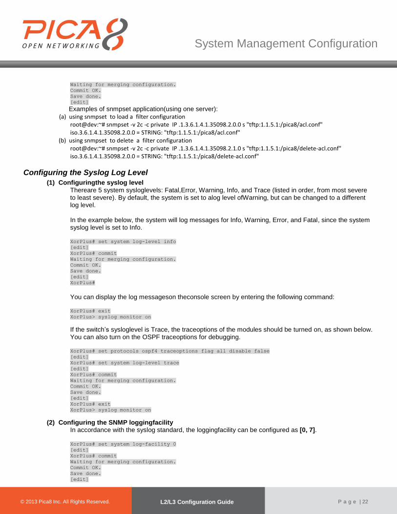
Examples of snmpset application(using one server):
(a) using snmpset to load a filter configuration root@dev:~# snmpset -v 2c -c private IP .1.3.6.1.4.1.35098.2.0.0 s "tftp:1.1.5.1:/pica8/acl.conf" iso.3.6.1.4.1.35098.2.0.0 = STRING: "tftp:1.1.5.1:/pica8/acl.conf"
(b) using snmpset to delete a filter configuration root@dev:~# snmpset -v 2c -c private IP .1.3.6.1.4.1.35098.2.1.0 s "tftp:1.1.5.1:/pica8/delete-acl.conf" iso.3.6.1.4.1.35098.2.0.0 = STRING: "tftp:1.1.5.1:/pica8/delete-acl.conf"
Configuring the Syslog Log Level
(1) Configuringthe syslog level Thereare 5 system sysloglevels: Fatal,Error, Warning, Info, and Trace (listed in order, from most severe to least severe). By default, the system is set to alog level ofWarning, but can be changed to a different log level. In the example below, the system will log messages for Info, Warning, Error, and Fatal, since the system syslog level is set to Info. XorPlus# set system log-level info
[edit]
XorPlus# commit
Waiting for merging configuration.
Commit OK.
Save done.
[edit]
XorPlus#
You can display the log messageson theconsole screen by entering the following command: XorPlus# exit
XorPlus> syslog monitor on
If the switch’s sysloglevel is Trace, the traceoptions of the modules should be turned on, as shown below. You can also turn on the OSPF traceoptions for debugging. XorPlus# set protocols ospf4 traceoptions flag all disable false
[edit]
XorPlus# set system log-level trace
[edit]
XorPlus# commit
Waiting for merging configuration.
Commit OK.
Save done.
[edit]
XorPlus# exit
XorPlus> syslog monitor on
(2) Configuring the SNMP loggingfacility In accordance with the syslog standard, the loggingfacility can be configured as [0, 7]. XorPlus# set system log-facility 0
[edit]
XorPlus# commit
Waiting for merging configuration.
Commit OK.
Save done.
[edit]

© 2012 Pica8 Inc. All © 2012 Pica8 Inc. All
System Management Configuration
© 2013 Pica8 Inc. All Rights Reserved. L2/L3 Configuration Guide
P a g e | 23
XorPlus#
Oct 17 15:22:42 XorPlus local0.warn : admin logined the switch
Oct 17 15:22:50 XorPlus local0.warn pica_sh: Tacacs send acct body send failed: wrote -1 of 127:
Connection refused
XorPlus# set system log-facility 2
[edit]
XorPlus# commit
Waiting for merging configuration.
Commit OK.
Save done.
[edit]
XorPlus#
Oct 17 15:22:42 XorPlus local2.warn : admin logined the switch
Configuring the Syslog Disk
(1) Configuring the syslog host After you configure the syslog server IP address, thelog files will be sent to the syslog server. XorPlus# set system syslog host 192.168.1.1
[edit]
XorPlus# commit
Waiting for merging configuration.
Commit OK.
Save done.
[edit]
XorPlus#
(2) Configuring syslog for local storage You can configure syslog messages to be stored in RAM or in a local SD card. XorPlus# set system syslog local-file disk
[edit]
XorPlus# commit
Waiting for merging configuration.
Commit OK.
Save done.
[edit]
XorPlus#
XorPlus# set system syslog local-file ram
[edit]
XorPlus# commit
Waiting for merging configuration.
Commit OK.
Save done.
[edit]
XorPlus#
Updating the PicOS Software and Platform
Youcan separate the system’s PicOS Platform and PicOS Software and update them respectively. Generally, rootfs.tar.gz will include both the PicOSPlatform and PisOSSoftware, and pica.tar.gz will include only the PicOSSoftware. (1) Displaying the system version
XorPlus# run show version
Copyright (C) 2009-2013 Pica8, Inc.
Base ethernet MAC Address : 08:9e:01:61:65:80
Hardware model : P-3290
PicOS Version : 2.0

© 2012 Pica8 Inc. All © 2012 Pica8 Inc. All
System Management Configuration
© 2013 Pica8 Inc. All Rights Reserved. L2/L3 Configuration Guide
P a g e | 24
Revision ID : 10863
(2) Updating the PicOS Software XorPlus> file tftp get remote-file pica.tar.gz local-filepica.tar.gz ip-address 1.1.5.6
XorPlus> configure
XorPlus# save running-to-startup(//save the current config to startup config if necessary)
XorPlus# run request system reboot
The image will be placed under the local installation directory (/cftmp). The system will decompress pica.tar.gzautomatically when rebooted,updating only the PicOS Software.
(3) Updating the PicOS Platform
XorPlus> file tftp get remote-file rootfs.tar.gz local-filepica.tar.gz ip-address 1.1.5.6
XorPlus> configure
XorPlus# save running-to-startup(//save the current config to startup config if necessary)
XorPlus# run request system reboot
The image will be placed under the local installation directory (/cftmp). The system will decompressrootfs.tar.gz automatically when rebooted, updating both the PicOS Platform and PicOS Software.
Displaying System Information
You can displayyour system’s information, including fan, power supply unit, and serialnumber information. (1) Displaying the system fan
XorPlus>show system fan
Sensor Temperature:
Sensor 1 Temperature : 42 Centigrade
Sensor 2 Temperature : 39 Centigrade
Sensor 3 Temperature : 46 Centigrade
Sensor 4 Temperature : 33 Centigrade
Fan Status:
Fan 1 speed = 12529 RPM, PWM = 79
Fan 2 speed = 12413 RPM, PWM = 79
Fan 3 speed = 12300 RPM, PWM = 79
(2) Displaying the system power supply unit
XorPlus> show system rpsu
RPSU 1:
TEMPERATURE_1 : N/A
RPSU 2:
TEMPERATURE_1 : 38.00 Centigrade
TEMPERATURE_2 : 40.00 Centigrade
FAN_SPEED : 10784.0 RPM
FAN_PWM : 60
(3) Displaying the system serial number XorPlus> show system serial-number
MotherBoard Serial Number : QTFCXI2460009
RPSU 1 Serial Number : N/A
RPSU 2 Serial Number : 601G10103C370ZG
SFP te-1/1/49 :
Vendor Name : PICA8
Serial Number : 78613B10987

© 2012 Pica8 Inc. All © 2012 Pica8 Inc. All
System Management Configuration
© 2013 Pica8 Inc. All Rights Reserved. L2/L3 Configuration Guide
P a g e | 25
Module Type : SR/850nm
Cable Length : 80m
SFP te-1/1/50 :
Vendor Name : JESS-LINK
Serial Number : 12344D0001
Cable Length : 5m
SFP te-1/1/51 :
Vendor Name : DELTA
Serial Number : 084109000017
Module Type : SR/850nm
Cable Length : 80m
SFP te-1/1/52 :
Vendor Name : JESS-LINK
Serial Number : 12344D0002
Cable Length : 5m
(4) Displaying additional system information XorPlus# run show system temperature
Temperature: 41 Centigrade
XorPlus#
XorPlus# run show system uptime
01:21:33 up 50 min, load average: 0.04, 0.06, 0.07
XorPlus#
XorPlus# run show system cpu-usage
Cpu usage: 15%
XorPlus#
XorPlus# run show system rollback ?
Possible completions:
compare Show the difference between tow rolled back configurations
file Show rolled back configuration file
list Show rolled back file list
XorPlus# run show system rollback compare to 02
637,639d636
< open-flow {
< working-mode: "l2/l3-mode"
< }
753c750
< enable: true
---
> enable: false
XorPlus#
XorPlus# run show system rollback file 02
/*XORP Configuration File, v1.0*/
interface {
ecmp {
max-path: 4
hash-mapping {
field {
ingress-interface {
disable: true
}
vlan {
disable: true
}
ip-protocol {
disable: true
}
ip-source {
disable: false
}
ip-destination {
disable: false
}
port-source {
disable: false
}
© 2012 Pica8 Inc. All © 2012 Pica8 Inc. All
System Management Configuration
© 2013 Pica8 Inc. All Rights Reserved. L2/L3 Configuration Guide
P a g e | 26
port-destination {
disable: false
}
}
}
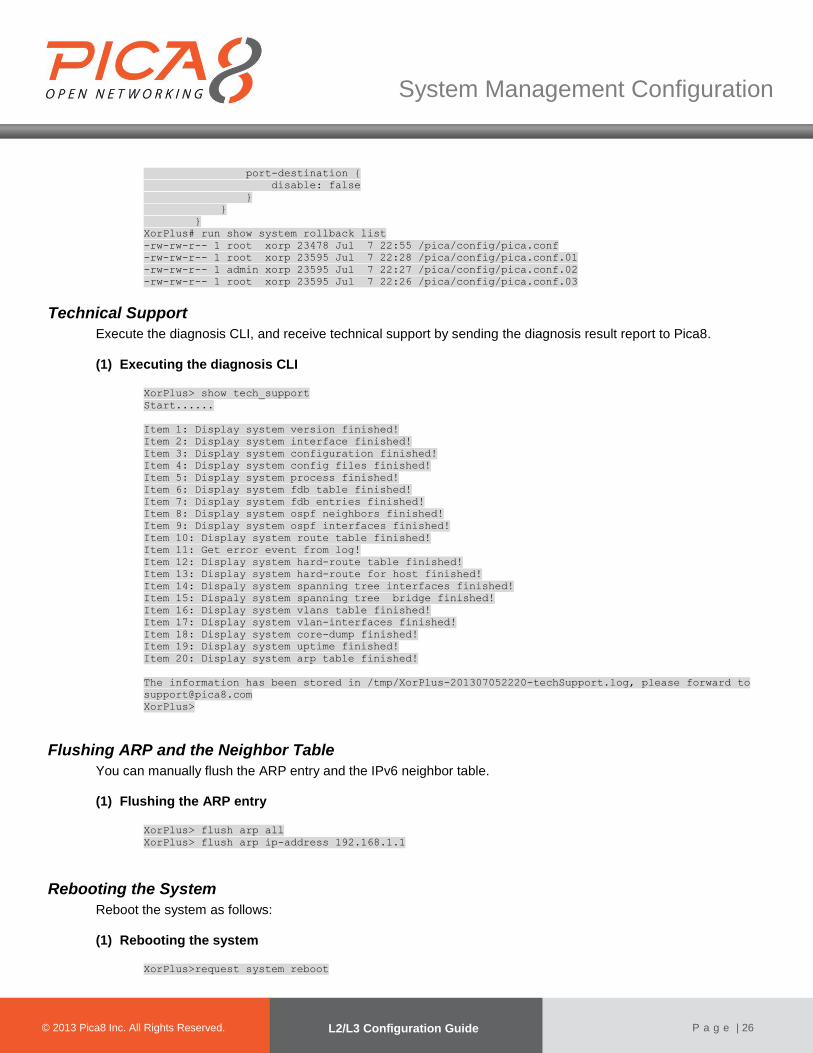
XorPlus# run show system rollback list
-rw-rw-r-- 1 root xorp 23478 Jul 7 22:55 /pica/config/pica.conf
-rw-rw-r-- 1 root xorp 23595 Jul 7 22:28 /pica/config/pica.conf.01
-rw-rw-r-- 1 admin xorp 23595 Jul 7 22:27 /pica/config/pica.conf.02
-rw-rw-r-- 1 root xorp 23595 Jul 7 22:26 /pica/config/pica.conf.03
Technical Support
Execute the diagnosis CLI, and receive technical support by sending the diagnosis result report to Pica8. (1) Executing the diagnosis CLI
XorPlus> show tech_support
Start......
Item 1: Display system version finished!
Item 2: Display system interface finished!
Item 3: Display system configuration finished!
Item 4: Display system config files finished!
Item 5: Display system process finished!
Item 6: Display system fdb table finished!
Item 7: Display system fdb entries finished!
Item 8: Display system ospf neighbors finished!
Item 9: Display system ospf interfaces finished!
Item 10: Display system route table finished!
Item 11: Get error event from log!
Item 12: Display system hard-route table finished!
Item 13: Display system hard-route for host finished!
Item 14: Dispaly system spanning tree interfaces finished!
Item 15: Dispaly system spanning tree bridge finished!
Item 16: Display system vlans table finished!
Item 17: Display system vlan-interfaces finished!
Item 18: Display system core-dump finished!
Item 19: Display system uptime finished!
Item 20: Display system arp table finished!
The information has been stored in /tmp/XorPlus-201307052220-techSupport.log, please forward to
XorPlus>
Flushing ARP and the Neighbor Table
You can manually flush the ARP entry and the IPv6 neighbor table. (1) Flushing the ARP entry
XorPlus> flush arp all
XorPlus> flush arp ip-address 192.168.1.1
Rebooting the System
Reboot the system as follows: (1) Rebooting the system
XorPlus>request system reboot

© 2012 Pica8 Inc. All © 2012 Pica8 Inc. All
System Management Configuration
© 2013 Pica8 Inc. All Rights Reserved. L2/L3 Configuration Guide
P a g e | 27
U-Boot 1.3.0 (Apr 11 2011 - 10:41:10)
CPU: 8541, Version: 1.1, (0x80720011)
Core: E500, Version: 2.0, (0x80200020)
Clock Configuration:
CPU: 825 MHz, CCB: 330 MHz,
DDR: 165 MHz, LBC: 41 MHz
L1: D-cache 32 kB enabled
I-cache 32 kB enabled
I2C: ready
DRAM: Initializing
DDR: 512 MB
FLASH: 32 MB
L2 cache 256KB: enabled
Set ethaddr MAC address = 60:eb:69:d2:9c:d8
In: serial
Out: serial
Err: serial
Net: TSEC0
IDE: Bus 0: OK
Device 0: Model: TRANSCEND Firm: 20091130 Ser#: 20100723 C4130E83
Type: Hard Disk
Capacity: 1911.6 MB = 1.8 GB (3915072 x 512)
Displaying the Debugging Message
You can configure the debugging message in your current window. (1) Syslog monitor on
XorPlus> syslog monitor on
Nov 21 2000 22:27:39 XorPlus local0.warn : [SIF]Interface ge-1/1/3, changed state to up
Nov 21 2000 22:27:41 XorPlus local0.warn : root logined the switch
Nov 21 2000 22:41:18 XorPlus local0.info xinetd[1102]: START: telnet pid=7650 from=10.10.50.16
Nov 21 2000 22:41:23 XorPlus authpriv.debug login[7651]: pam_unix(login:account): account admin
has password changed in future
Nov 21 2000 22:41:26 XorPlus local0.warn : admin logined the switch
Nov 21 2000 22:55:58 XorPlus local0.info xinetd[1102]: START: telnet pid=8039 from=10.10.51.16
Nov 21 2000 22:56:01 XorPlus authpriv.debug login[8040]: pam_unix(login:account): account root
has password changed in future
Nov 21 2000 23:31:13 XorPlus local0.info xinetd[1102]: START: telnet pid=9028 from=10.10.50.16
Nov 21 2000 23:31:16 XorPlus authpriv.debug login[9029]: pam_unix(login:account): account admin
has password changed in future
Nov 21 2000 23:31:21 XorPlus local0.warn : admin logined the switch
XorPlus>
Installing Software
You can install software that you’d like to have inyour Debian system(e.g.make, python, g++) as shown below:
(1) Updating the software list on the source server
root@XorPlus#apt-get update
Hit http://ftp.tw.debian.org stable Release.gpg
Hit http://ftp.tw.debian.org stable Release
Hit http://ftp.tw.debian.org stable/main powerpc Packages
Hit http://ftp.tw.debian.org stable/main Translation-en
Reading package lists... Done
root@XorPlus#
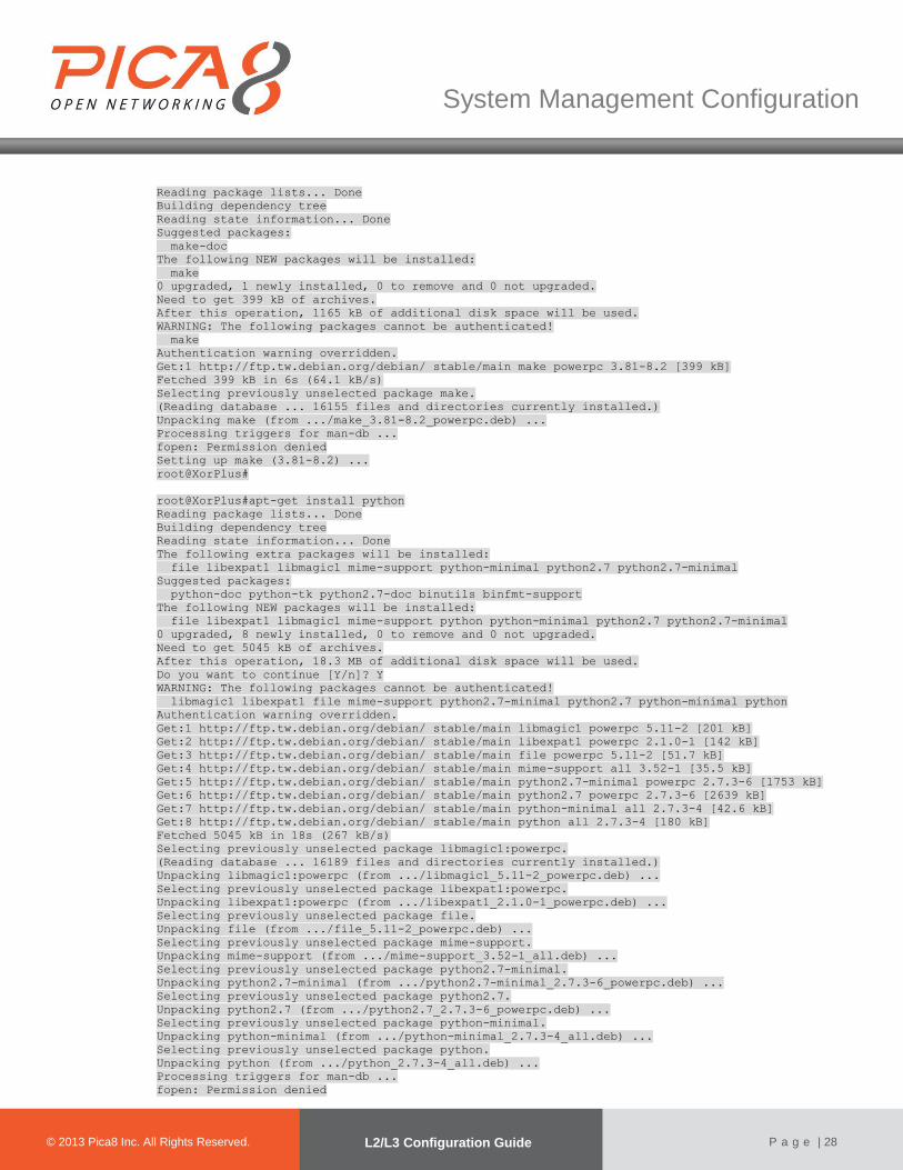
(2) Installing newsoftware root@XorPlus#apt-get install make
© 2012 Pica8 Inc. All © 2012 Pica8 Inc. All
System Management Configuration
© 2013 Pica8 Inc. All Rights Reserved. L2/L3 Configuration Guide
P a g e | 28
Reading package lists... Done
Building dependency tree
Reading state information... Done
Suggested packages:
make-doc
The following NEW packages will be installed:
make
0 upgraded, 1 newly installed, 0 to remove and 0 not upgraded.
Need to get 399 kB of archives.
After this operation, 1165 kB of additional disk space will be used.
WARNING: The following packages cannot be authenticated!
make
Authentication warning overridden.
Get:1 http://ftp.tw.debian.org/debian/ stable/main make powerpc 3.81-8.2 [399 kB]
Fetched 399 kB in 6s (64.1 kB/s)
Selecting previously unselected package make.
(Reading database ... 16155 files and directories currently installed.)
Unpacking make (from .../make_3.81-8.2_powerpc.deb) ...
Processing triggers for man-db ...
fopen: Permission denied
Setting up make (3.81-8.2) ...
root@XorPlus#
root@XorPlus#apt-get install python
Reading package lists... Done
Building dependency tree
Reading state information... Done
The following extra packages will be installed:
file libexpat1 libmagic1 mime-support python-minimal python2.7 python2.7-minimal
Suggested packages:
python-doc python-tk python2.7-doc binutils binfmt-support
The following NEW packages will be installed:
file libexpat1 libmagic1 mime-support python python-minimal python2.7 python2.7-minimal
0 upgraded, 8 newly installed, 0 to remove and 0 not upgraded.
Need to get 5045 kB of archives.
After this operation, 18.3 MB of additional disk space will be used.
Do you want to continue [Y/n]? Y
WARNING: The following packages cannot be authenticated!
libmagic1 libexpat1 file mime-support python2.7-minimal python2.7 python-minimal python
Authentication warning overridden.
Get:1 http://ftp.tw.debian.org/debian/ stable/main libmagic1 powerpc 5.11-2 [201 kB]
Get:2 http://ftp.tw.debian.org/debian/ stable/main libexpat1 powerpc 2.1.0-1 [142 kB]
Get:3 http://ftp.tw.debian.org/debian/ stable/main file powerpc 5.11-2 [51.7 kB]
Get:4 http://ftp.tw.debian.org/debian/ stable/main mime-support all 3.52-1 [35.5 kB]
Get:5 http://ftp.tw.debian.org/debian/ stable/main python2.7-minimal powerpc 2.7.3-6 [1753 kB]
Get:6 http://ftp.tw.debian.org/debian/ stable/main python2.7 powerpc 2.7.3-6 [2639 kB]
Get:7 http://ftp.tw.debian.org/debian/ stable/main python-minimal all 2.7.3-4 [42.6 kB]
Get:8 http://ftp.tw.debian.org/debian/ stable/main python all 2.7.3-4 [180 kB]
Fetched 5045 kB in 18s (267 kB/s)
Selecting previously unselected package libmagic1:powerpc.
(Reading database ... 16189 files and directories currently installed.)
Unpacking libmagic1:powerpc (from .../libmagic1_5.11-2_powerpc.deb) ...
Selecting previously unselected package libexpat1:powerpc.
Unpacking libexpat1:powerpc (from .../libexpat1_2.1.0-1_powerpc.deb) ...
Selecting previously unselected package file.
Unpacking file (from .../file_5.11-2_powerpc.deb) ...
Selecting previously unselected package mime-support.
Unpacking mime-support (from .../mime-support_3.52-1_all.deb) ...
Selecting previously unselected package python2.7-minimal.
Unpacking python2.7-minimal (from .../python2.7-minimal_2.7.3-6_powerpc.deb) ...
Selecting previously unselected package python2.7.
Unpacking python2.7 (from .../python2.7_2.7.3-6_powerpc.deb) ...
Selecting previously unselected package python-minimal.
Unpacking python-minimal (from .../python-minimal_2.7.3-4_all.deb) ...
Selecting previously unselected package python.
Unpacking python (from .../python_2.7.3-4_all.deb) ...
Processing triggers for man-db ...
fopen: Permission denied
© 2012 Pica8 Inc. All © 2012 Pica8 Inc. All
System Management Configuration
© 2013 Pica8 Inc. All Rights Reserved. L2/L3 Configuration Guide
P a g e | 29
Setting up libmagic1:powerpc (5.11-2) ...
Setting up libexpat1:powerpc (2.1.0-1) ...
Setting up file (5.11-2) ...
Setting up mime-support (3.52-1) ...
Setting up python2.7-minimal (2.7.3-6) ...
Linking and byte-compiling packages for runtime python2.7...
Setting up python2.7 (2.7.3-6) ...
Setting up python-minimal (2.7.3-4) ...
Setting up python (2.7.3-4) ...
root@XorPlus#
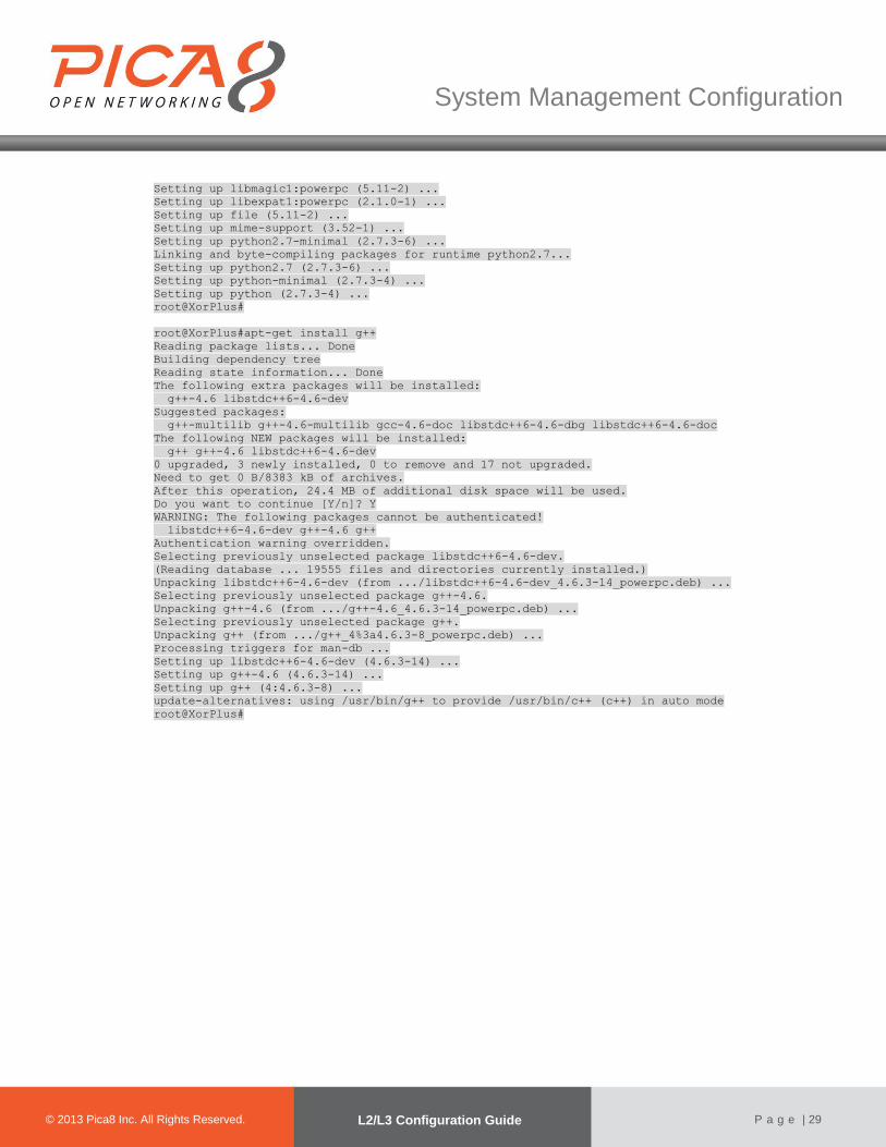
root@XorPlus#apt-get install g++
Reading package lists... Done
Building dependency tree
Reading state information... Done
The following extra packages will be installed:
g++-4.6 libstdc++6-4.6-dev
Suggested packages:
g++-multilib g++-4.6-multilib gcc-4.6-doc libstdc++6-4.6-dbg libstdc++6-4.6-doc
The following NEW packages will be installed:
g++ g++-4.6 libstdc++6-4.6-dev
0 upgraded, 3 newly installed, 0 to remove and 17 not upgraded.
Need to get 0 B/8383 kB of archives.
After this operation, 24.4 MB of additional disk space will be used.
Do you want to continue [Y/n]? Y
WARNING: The following packages cannot be authenticated!
libstdc++6-4.6-dev g++-4.6 g++
Authentication warning overridden.
Selecting previously unselected package libstdc++6-4.6-dev.
(Reading database ... 19555 files and directories currently installed.)
Unpacking libstdc++6-4.6-dev (from .../libstdc++6-4.6-dev_4.6.3-14_powerpc.deb) ...
Selecting previously unselected package g++-4.6.
Unpacking g++-4.6 (from .../g++-4.6_4.6.3-14_powerpc.deb) ...
Selecting previously unselected package g++.
Unpacking g++ (from .../g++_4%3a4.6.3-8_powerpc.deb) ...
Processing triggers for man-db ...
Setting up libstdc++6-4.6-dev (4.6.3-14) ...
Setting up g++-4.6 (4.6.3-14) ...
Setting up g++ (4:4.6.3-8) ...
update-alternatives: using /usr/bin/g++ to provide /usr/bin/c++ (c++) in auto mode
root@XorPlus#
File Management Configuration
© 2012 Pica8 Inc. All © 2012 Pica8 Inc. All
© 2013 Pica8 Inc. All Rights Reserved. Configuration Guide
P a g e | 30
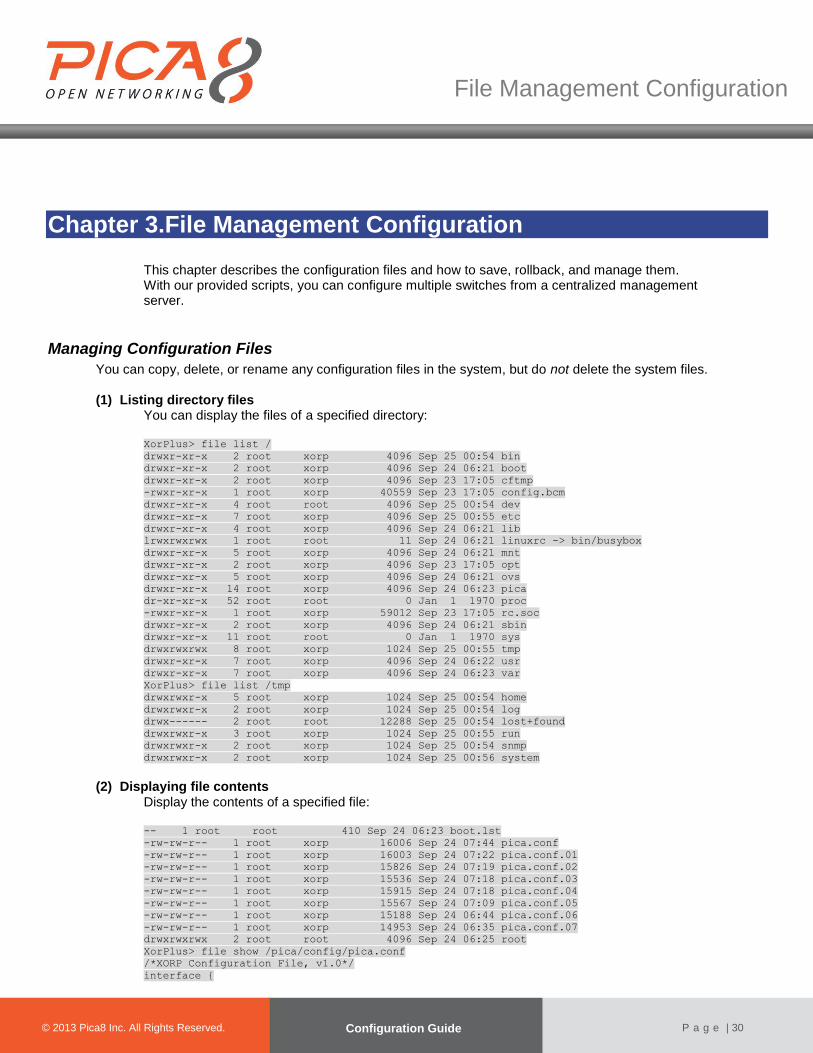
Chapter 3.File Management Configuration
This chapter describes the configuration files and how to save, rollback, and manage them. With our provided scripts, you can configure multiple switches from a centralized management server.
Managing Configuration Files
You can copy, delete, or rename any configuration files in the system, but do not delete the system files. (1) Listing directory files
You can display the files of a specified directory:
XorPlus> file list /
drwxr-xr-x 2 root xorp 4096 Sep 25 00:54 bin
drwxr-xr-x 2 root xorp 4096 Sep 24 06:21 boot
drwxr-xr-x 2 root xorp 4096 Sep 23 17:05 cftmp
-rwxr-xr-x 1 root xorp 40559 Sep 23 17:05 config.bcm
drwxr-xr-x 4 root root 4096 Sep 25 00:54 dev
drwxr-xr-x 7 root xorp 4096 Sep 25 00:55 etc
drwxr-xr-x 4 root xorp 4096 Sep 24 06:21 lib
lrwxrwxrwx 1 root root 11 Sep 24 06:21 linuxrc -> bin/busybox
drwxr-xr-x 5 root xorp 4096 Sep 24 06:21 mnt
drwxr-xr-x 2 root xorp 4096 Sep 23 17:05 opt
drwxr-xr-x 5 root xorp 4096 Sep 24 06:21 ovs
drwxr-xr-x 14 root xorp 4096 Sep 24 06:23 pica
dr-xr-xr-x 52 root root 0 Jan 1 1970 proc
-rwxr-xr-x 1 root xorp 59012 Sep 23 17:05 rc.soc
drwxr-xr-x 2 root xorp 4096 Sep 24 06:21 sbin
drwxr-xr-x 11 root root 0 Jan 1 1970 sys
drwxrwxrwx 8 root xorp 1024 Sep 25 00:55 tmp
drwxr-xr-x 7 root xorp 4096 Sep 24 06:22 usr
drwxr-xr-x 7 root xorp 4096 Sep 24 06:23 var
XorPlus> file list /tmp
drwxrwxr-x 5 root xorp 1024 Sep 25 00:54 home
drwxrwxr-x 2 root xorp 1024 Sep 25 00:54 log
drwx------ 2 root root 12288 Sep 25 00:54 lost+found
drwxrwxr-x 3 root xorp 1024 Sep 25 00:55 run
drwxrwxr-x 2 root xorp 1024 Sep 25 00:54 snmp
drwxrwxr-x 2 root xorp 1024 Sep 25 00:56 system
(2) Displaying file contents Display the contents of a specified file:
-- 1 root root 410 Sep 24 06:23 boot.lst
-rw-rw-r-- 1 root xorp 16006 Sep 24 07:44 pica.conf
-rw-rw-r-- 1 root xorp 16003 Sep 24 07:22 pica.conf.01
-rw-rw-r-- 1 root xorp 15826 Sep 24 07:19 pica.conf.02
-rw-rw-r-- 1 root xorp 15536 Sep 24 07:18 pica.conf.03
-rw-rw-r-- 1 root xorp 15915 Sep 24 07:18 pica.conf.04
-rw-rw-r-- 1 root xorp 15567 Sep 24 07:09 pica.conf.05
-rw-rw-r-- 1 root xorp 15188 Sep 24 06:44 pica.conf.06
-rw-rw-r-- 1 root xorp 14953 Sep 24 06:35 pica.conf.07
drwxrwxrwx 2 root root 4096 Sep 24 06:25 root
XorPlus> file show /pica/config/pica.conf
/*XORP Configuration File, v1.0*/
interface {
© 2012 Pica8 Inc. All © 2012 Pica8 Inc. All
File Management Configuration
© 2013 Pica8 Inc. All Rights Reserved. L2/L3 Configuration Guide
P a g e | 31
ecmp {
max-path: 4
hash-mapping {
field {
ingress-interface {
disable: false
}
vlan {
disable: false
}
ip-protocol {
disable: false
}
ip-source {
disable: false
}
ip-destination {
disable: false
}
port-source {
disable: false
}
port-destination {
disable: false
}
}
}
}
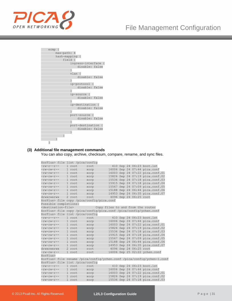
(3) Additional file management commands You can also copy, archive, checksum, compare, rename, and sync files.
XorPlus> file list /pica/config
-rw-r--r-- 1 root root 410 Sep 24 06:23 boot.lst
-rw-rw-r-- 1 root xorp 16006 Sep 24 07:44 pica.conf
-rw-rw-r-- 1 root xorp 16003 Sep 24 07:22 pica.conf.01
-rw-rw-r-- 1 root xorp 15826 Sep 24 07:19 pica.conf.02
-rw-rw-r-- 1 root xorp 15536 Sep 24 07:18 pica.conf.03
-rw-rw-r-- 1 root xorp 15915 Sep 24 07:18 pica.conf.04
-rw-rw-r-- 1 root xorp 15567 Sep 24 07:09 pica.conf.05
-rw-rw-r-- 1 root xorp 15188 Sep 24 06:44 pica.conf.06
-rw-rw-r-- 1 root xorp 14953 Sep 24 06:35 pica.conf.07
drwxrwxrwx 2 root root 4096 Sep 24 06:25 root
XorPlus> file copy /pica/config/pica.conf
Possible completions:
<destination-file> Copy files to and from the router
XorPlus> file copy /pica/config/pica.conf /pica/config/ychen.conf
XorPlus> file list /pica/config
-rw-r--r-- 1 root root 410 Sep 24 06:23 boot.lst
-rw-rw-r-- 1 root xorp 16006 Sep 24 07:44 pica.conf
-rw-rw-r-- 1 root xorp 16003 Sep 24 07:22 pica.conf.01
-rw-rw-r-- 1 root xorp 15826 Sep 24 07:19 pica.conf.02
-rw-rw-r-- 1 root xorp 15536 Sep 24 07:18 pica.conf.03
-rw-rw-r-- 1 root xorp 15915 Sep 24 07:18 pica.conf.04
-rw-rw-r-- 1 root xorp 15567 Sep 24 07:09 pica.conf.05
-rw-rw-r-- 1 root xorp 15188 Sep 24 06:44 pica.conf.06
-rw-rw-r-- 1 root xorp 14953 Sep 24 06:35 pica.conf.07
drwxrwxrwx 2 root root 4096 Sep 24 06:25 root
-rw-rw-r-- 1 root root 16006 Sep 25 02:22 ychen.conf
XorPlus>
XorPlus> file rename /pica/config/ychen.conf /pica/config/ychen-1.conf
XorPlus> file list /pica/config
-rw-r--r-- 1 root root 410 Sep 24 06:23 boot.lst
-rw-rw-r-- 1 root xorp 16006 Sep 24 07:44 pica.conf
-rw-rw-r-- 1 root xorp 16003 Sep 24 07:22 pica.conf.01
-rw-rw-r-- 1 root xorp 15826 Sep 24 07:19 pica.conf.02
-rw-rw-r-- 1 root xorp 15536 Sep 24 07:18 pica.conf.03

© 2012 Pica8 Inc. All © 2012 Pica8 Inc. All
File Management Configuration
© 2013 Pica8 Inc. All Rights Reserved. L2/L3 Configuration Guide
P a g e | 32
-rw-rw-r-- 1 root xorp 15915 Sep 24 07:18 pica.conf.04
-rw-rw-r-- 1 root xorp 15567 Sep 24 07:09 pica.conf.05
-rw-rw-r-- 1 root xorp 15188 Sep 24 06:44 pica.conf.06
-rw-rw-r-- 1 root xorp 14953 Sep 24 06:35 pica.conf.07
drwxrwxrwx 2 root root 4096 Sep 24 06:25 root
-rw-rw-r-- 1 root root 16006 Sep 25 02:22 ychen-1.conf
XorPlus>
XorPlus> file checksum /pica/config/ychen-1.conf
3559192236 16006 /pica/config/ychen-1.conf
XorPlus>
XorPlus> file sync
XorPlus>
XorPlus> file compare /pica/config/pica.conf /pica/config/pica.conf.01
--- /pica/config/pica.conf Mon Sep 24 07:44:45 2012
+++ /pica/config/pica.conf.01 Mon Sep 24 07:22:37 2012
@@ -5,13 +5,13 @@
hash-mapping {
field {
ingress-interface {
- disable: false
+ disable: true
}
vlan {
- disable: false
+ disable: true
}
ip-protocol {
- disable: false
+ disable: true
}
ip-source {
disable: false
Displaying Your Current Configuration
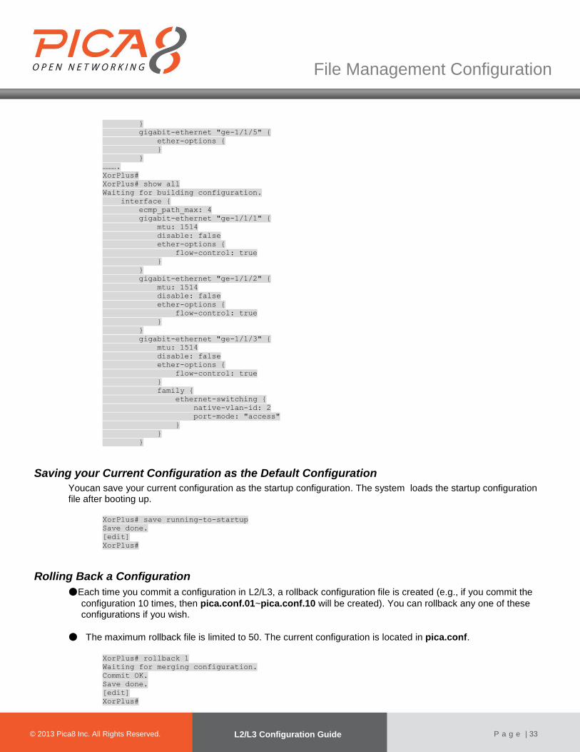
In L2/L3, you can display your non-default configuration with the show command. Display all configurations using the show all command.
XorPlus# show
Waiting for building configuration.
interface {
gigabit-ethernet "ge-1/1/1" {
ether-options {
}
}
gigabit-ethernet "ge-1/1/2" {
ether-options {
}
}
gigabit-ethernet "ge-1/1/3" {
ether-options {
}
family {
ethernet-switching {
native-vlan-id: 2
}
}
}
gigabit-ethernet "ge-1/1/4" {
ether-options {
}
family {
ethernet-switching {
native-vlan-id: 3
}
}
© 2012 Pica8 Inc. All © 2012 Pica8 Inc. All
File Management Configuration
© 2013 Pica8 Inc. All Rights Reserved. L2/L3 Configuration Guide
P a g e | 33
}
gigabit-ethernet "ge-1/1/5" {
ether-options {
}
}
……….
XorPlus#
XorPlus# show all
Waiting for building configuration.
interface {
ecmp_path_max: 4
gigabit-ethernet "ge-1/1/1" {
mtu: 1514
disable: false
ether-options {
flow-control: true
}
}
gigabit-ethernet "ge-1/1/2" {
mtu: 1514
disable: false
ether-options {
flow-control: true
}
}
gigabit-ethernet "ge-1/1/3" {
mtu: 1514
disable: false
ether-options {
flow-control: true
}
family {
ethernet-switching {
native-vlan-id: 2
port-mode: "access"
}
}
}
Saving your Current Configuration as the Default Configuration
Youcan save your current configuration as the startup configuration. The system loads the startup configuration file after booting up.
XorPlus# save running-to-startup
Save done.
[edit]
XorPlus#
Rolling Back a Configuration
●Each time you commit a configuration in L2/L3, a rollback configuration file is created (e.g., if you commit the
configuration 10 times, then pica.conf.01~pica.conf.10 will be created). You can rollback any one of these configurations if you wish.
● The maximum rollback file is limited to 50. The current configuration is located in pica.conf.
XorPlus# rollback 1
Waiting for merging configuration.
Commit OK.
Save done.
[edit]
XorPlus#
© 2012 Pica8 Inc. All © 2012 Pica8 Inc. All
File Management Configuration
© 2013 Pica8 Inc. All Rights Reserved. L2/L3 Configuration Guide
P a g e | 34
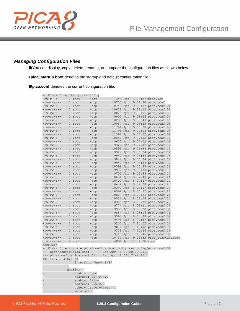
Managing Configuration Files
●You can display, copy, delete, rename, or compare the configuration files as shown below.
●pica_startup.boot denotes the startup and default configuration file.
●pica.conf denotes the current configuration file.
XorPlus> file list pica/config
-rw-r--r-- 1 root root 344 Apr 1 02:27 boot.lst
-rw-rw-r-- 1 root xorp 10750 Apr 9 09:20 pica.conf
-rw-rw-r-- 1 root xorp 10749 Apr 9 09:17 pica.conf.01
-rw-rw-r-- 1 root xorp 10619 Apr 9 09:15 pica.conf.02
-rw-rw-r-- 1 root xorp 10023 Apr 9 08:56 pica.conf.03
-rw-rw-r-- 1 root xorp 9902 Apr 9 08:56 pica.conf.04
-rw-rw-r-- 1 root xorp 10238 Apr 9 08:43 pica.conf.05
-rw-rw-r-- 1 root xorp 10057 Apr 9 08:43 pica.conf.06
-rw-rw-r-- 1 root xorp 11796 Apr 9 08:37 pica.conf.07
-rw-rw-r-- 1 root xorp 11796 Apr 9 07:05 pica.conf.08
-rw-rw-r-- 1 root xorp 11364 Apr 9 07:02 pica.conf.09
-rw-rw-r-- 1 root xorp 10057 Apr 9 07:02 pica.conf.10
-rw-rw-r-- 1 root xorp 9625 Apr 9 07:02 pica.conf.11
-rw-rw-r-- 1 root xorp 9322 Apr 9 07:02 pica.conf.12
-rw-rw-r-- 1 root xorp 10599 Apr 9 06:34 pica.conf.13
-rw-rw-r-- 1 root xorp 9947 Apr 9 06:34 pica.conf.14
-rw-rw-r-- 1 root xorp 9947 Apr 9 06:34 pica.conf.15
-rw-rw-r-- 1 root xorp 9848 Apr 9 06:34 pica.conf.16
-rw-rw-r-- 1 root xorp 9947 Apr 9 06:34 pica.conf.17
-rw-rw-r-- 1 root xorp 10599 Apr 9 06:33 pica.conf.18
-rw-rw-r-- 1 root xorp 9912 Apr 9 06:33 pica.conf.19
-rw-rw-r-- 1 root xorp 9702 Apr 9 06:33 pica.conf.20
-rw-rw-r-- 1 root xorp 10604 Apr 8 07:47 pica.conf.21
-rw-rw-r-- 1 root xorp 10402 Apr 8 07:47 pica.conf.22
-rw-rw-r-- 1 root xorp 10402 Apr 8 07:27 pica.conf.23
-rw-rw-r-- 1 root xorp 10390 Apr 8 06:47 pica.conf.24
-rw-rw-r-- 1 root xorp 10392 Apr 8 06:32 pica.conf.25
-rw-rw-r-- 1 root xorp 10023 Apr 8 06:25 pica.conf.26
-rw-rw-r-- 1 root xorp 10024 Apr 8 06:08 pica.conf.27
-rw-rw-r-- 1 root xorp 10305 Apr 8 03:27 pica.conf.28
-rw-rw-r-- 1 root xorp 9774 Apr 8 03:21 pica.conf.29
-rw-rw-r-- 1 root xorp 9958 Apr 8 03:20 pica.conf.30
-rw-rw-r-- 1 root xorp 9854 Apr 8 03:16 pica.conf.31
-rw-rw-r-- 1 root xorp 9567 Apr 8 03:08 pica.conf.32
-rw-rw-r-- 1 root xorp 9498 Apr 8 02:57 pica.conf.33
-rw-rw-r-- 1 root xorp 9257 Apr 7 10:52 pica.conf.34
-rw-rw-r-- 1 root xorp 9073 Apr 7 10:52 pica.conf.35
-rw-rw-r-- 1 root xorp 9311 Apr 7 10:46 pica.conf.36
-rw-rw-r-- 1 root xorp 9149 Apr 7 10:45 pica.conf.37
-rw-rw-r-- 1 root xorp 10750 Apr 9 09:32 pica_startup.boot
drwxrwxrwx 2 root root 4096 Apr 1 02:28 root
XorPlus>
XorPlus> file compare pica/config/pica.conf pica/config/pica.conf.01
--- pica/config/pica.conf Sat Apr 9 09:20:39 2011
+++ pica/config/pica.conf.01 Sat Apr 9 09:17:44 2011
@@ -410,8 +410,8 @@
interface "ge-1/1/3"
}
querier {
- enable: true
- address: 10.10.1.1
+ enable: false
+ address: 0.0.0.0
other-querier-timer: 1
version: 2
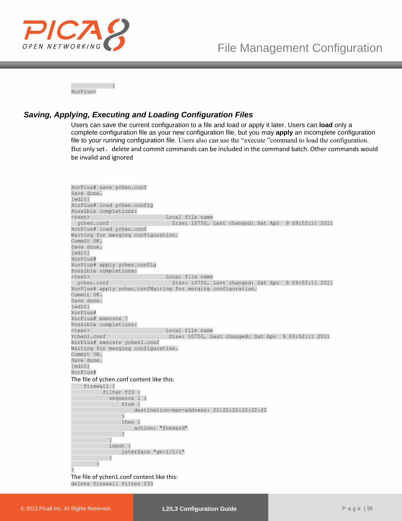
© 2012 Pica8 Inc. All © 2012 Pica8 Inc. All
File Management Configuration
© 2013 Pica8 Inc. All Rights Reserved. L2/L3 Configuration Guide
P a g e | 35
}
XorPlus>
Saving, Applying, Executing and Loading Configuration Files
Users can save the current configuration to a file and load or apply it later. Users can load only a complete configuration file as your new configuration file, but you may apply an incomplete configuration
file to your running configuration file. Users also can use the “execute ”command to load the configuration.
But only set、delete and commit commands can be included in the command batch. Other commands would be invalid and ignored
XorPlus# save ychen.conf
Save done.
[edit]
XorPlus# load ychen.config
Possible completions:
<text> Local file name
ychen.conf Size: 10750, Last changed: Sat Apr 9 09:52:11 2011
XorPlus# load ychen.conf
Waiting for merging configuration.
Commit OK.
Save done.
[edit]
XorPlus#
XorPlus# apply ychen.config
Possible completions:
<text> Local file name
ychen.conf Size: 10750, Last changed: Sat Apr 9 09:52:11 2011
XorPlus# apply ychen.confWaiting for merging configuration.
Commit OK.
Save done.
[edit]
XorPlus#
XorPlus# execute ?
Possible completions:
<text> Local file name
Ychen1.conf Size: 10750, Last changed: Sat Apr 9 09:52:11 2011 XorPlus# execute ychen1.conf
Waiting for merging configuration.
Commit OK.
Save done.
[edit]
XorPlus#
The file of ychen.conf content like this: firewall {
filter f33 {
sequence 1 {
from {
destination-mac-address: 22:22:22:22:22:22
}
then {
action: "forward"
}
}
input {
interface "ge-1/1/1"
}
}
}
The file of ychen1.conf content like this: delete firewall filter f33

© 2012 Pica8 Inc. All © 2012 Pica8 Inc. All
File Management Configuration
© 2013 Pica8 Inc. All Rights Reserved. L2/L3 Configuration Guide
P a g e | 36
commit

Layer2 Switching Configuration
© 2012 Pica8 Inc. All © 2012 Pica8 Inc. All
© 2013 Pica8 Inc. All Rights Reserved. Configuration Guide
P a g e | 37
Chapter 4.Layer2 Switching Configuration
This chapter describes the configuration steps of Layer2 switching, including MAC address learning, LLDP, LACP, 802.1Q VLAN, flow control, mirroring, storm control, and the Spanning Tree Protocol (STP/RSTP/MSTP).
Configuring LLDP (Link Layer Discovery Protocol)
●LLDP is a standard link-layer discovery protocol which can broadcast its capability, IP address, ID, and
interface name as TLVs (Type/Length/Value) in LLDP PDUs (Link Layer Discovery Protocol Data Units).
● An LLDP PDU includes 4 basic TLVs and several optional TLVs. Basic TLVs include the Chassis ID, Port
ID,TTL, and End TLVs.
●In L2/L3, you can select the following optional TLVs:
Table 3-1. Supported TLVs of L2/L3.
TLV Name Description
mac-phy-cfg MAC address of the system
management-address Management IP address of the system
port-description The port description of system
port-vlan The VLAN ID of the port
system-capabilities System capability (e.g. switching, routing)
system-description System description
system-name System name
(1) Configuring the LLDP mode
LLDP supports 4 modes: TxRx, Tx_only, Rx_only, and Disabled. InTxRx mode, the system transmitsand receives LLDPDUs. In Tx_only, the system only transmitsLLDPDUs. In Rx_only, the system only receives LLDPDUs. In Disabled, the system will not transmit or receive any LLDPDUs. You can configure the system as shown below:
XorPlus# set protocols lldp enable true
[edit]
XorPlus# set protocols lldp interface ge-1/1/1 status tx_rx
[edit]
XorPlus# commit
Waiting for merging configuration.
Commit OK.
Save done.
[edit]
XorPlus#
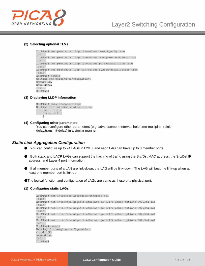
© 2012 Pica8 Inc. All © 2012 Pica8 Inc. All
Layer2 Switching Configuration
© 2013 Pica8 Inc. All Rights Reserved. L2/L3 Configuration Guide
P a g e | 38
(2) Selecting optional TLVs
XorPlus# set protocols lldp tlv-select mac-phy-cfg true
[edit]
XorPlus# set protocols lldp tlv-select management-address true
[edit]
XorPlus# set protocols lldp tlv-select port-description true
[edit]
XorPlus# set protocols lldp tlv-select system-capabilities true
[edit]
XorPlus# commit
Waiting for merging configuration.
Commit OK.
Save done.
[edit]
XorPlus#
(3) Displaying LLDP information
XorPlus# show protocols lldp
Waiting for building configuration.
enable: true
tlv-select {
}
(4) Configuring other parameters You can configure other parameters (e.g. advertisement-interval, hold-time-multiplier, reinit-delay,transmit-delay) in a similar manner.
Static Link Aggregation Configuration
● You can configure up to 24 LAGs in L2/L3, and each LAG can have up to 8 member ports.
● Both static and LACP LAGs can support the hashing of traffic using the Src/Dst MAC address, the Src/Dst IP
address, and Layer 4 port information.
● If all member ports of a LAN are link-down, the LAG will be link-down. The LAG will become link-up when at
least one member port is link-up.
●The logical function and configuration of LAGs are same as those of a physical port.
(1) Configuring static LAGs
XorPlus# set interface aggregate-ethernet ae1
[edit]
XorPlus# set interface gigabit-ethernet ge-1/1/1 ether-options 802.3ad ae1
[edit]
XorPlus# set interface gigabit-ethernet ge-1/1/2 ether-options 802.3ad ae1
[edit]
XorPlus# set interface gigabit-ethernet ge-1/1/3 ether-options 802.3ad ae1
[edit]
XorPlus# set interface gigabit-ethernet ge-1/1/4 ether-options 802.3ad ae1
[edit]
XorPlus# commit
Waiting for merging configuration.
Commit OK.
Save done.
[edit]
XorPlus#

© 2012 Pica8 Inc. All © 2012 Pica8 Inc. All
Layer2 Switching Configuration
© 2013 Pica8 Inc. All Rights Reserved. L2/L3 Configuration Guide
P a g e | 39
(2) Displaying static LAG information
XorPlus# run show interface aggregate-ethernet ae1
Physical interface: ae1, Enabled, Physical link is Up
Interface index: 53
Link-level type: Ethernet, MTU: 1514, Speed: Auto, Duplex: Auto
Source filtering: Disabled, Flow control: Enabled, Auto-negotiation: Enabled
Interface flags: Hardware-Down SNMP-Traps Internal: 0x0
Current address: c8:0a:a9:9e:14:9f, Hardware address: c8:0a:a9:9e:14:9f
Traffic statistics:
Input Packets............................176
Output Packets...........................16
Input Octets.............................12888
Output Octets............................1594
Aggregated link protocol: STATIC
Members Status Port Speed
--------- -------- ----------
ge-1/1/1 Down Auto
ge-1/1/2 Down Auto
ge-1/1/3 Up Auto
ge-1/1/4 Up Auto
Link Aggregation Control Protocol (LACP) Configuration
● LACP (802.3ad) provides the dynamic link aggregation function.
● The LACPDU includes the LACP system priority, the system’s MAC, the port priority and I.D. The port,
included in the LACP LAG, will transmit the LACPDU to its neighbors.
● The configuration of the LACP LAG is similar to that of the static LAG.
● min-selected-port denotes that the LAG is up only when no fewer than the defined number of ports are up.
Below, our defined number is 4. (1) Configuring LACP LAGs
XorPlus# set interface aggregate-ethernet ae1aggregated-ether-options lacp enable true
[edit]
XorPlus# set interface aggregate-ethernet ae1 aggregated-ether-options min-selected-port 4
[edit]
XorPlus# set interface gigabit-ethernet ge-1/1/1 ether-options 802.3ad ae1
[edit]
XorPlus# set interface gigabit-ethernet ge-1/1/2 ether-options 802.3ad ae1
[edit]
XorPlus# set interface gigabit-ethernet ge-1/1/3 ether-options 802.3ad ae1
[edit]
XorPlus# set interface gigabit-ethernet ge-1/1/4 ether-options 802.3ad ae1
[edit]
XorPlus# commit
Waiting for merging configuration.
Commit OK.
Save done.
[edit]
XorPlus#
(2) Displaying LACP LAG information
XorPlus# run show interface aggregate-ethernet ae1
Physical interface: ae1, Enabled, Physical link is Down
Interface index: 53

© 2012 Pica8 Inc. All © 2012 Pica8 Inc. All
Layer2 Switching Configuration
© 2013 Pica8 Inc. All Rights Reserved. L2/L3 Configuration Guide
P a g e | 40
Description:
Link-level type: Ethernet, MTU: 1514, Speed: Auto, Duplex: Auto
Source filtering: Disabled, Flow control: Enabled, Auto-negotiation: Enabled
Interface flags: Hardware-Down SNMP-Traps Internal: 0x0
Current address: 60:eb:69:d2:9c:d7, Hardware address: 60:eb:69:d2:9c:d7
Traffic statistics:
5 sec input rate 0 bits/sec, 0 packets/sec
5 sec output rate 0 bits/sec, 0 packets/sec
Input Packets............................0
Output Packets...........................0
Input Octets.............................0
Output Octets............................0
Aggregated link protocol: LACP
Minimum number of selected ports: 4
Members Status Port Speed
--------- ---------- ----------
ge-1/1/1 up(active) Auto
ge-1/1/2 up(active) Auto
ge-1/1/3 up(active) Auto
ge-1/1/4 up(active) Auto
MLAG Configuration Guide
Traditionally, an aggregation interface is a logical interface which used to increase the bandwidth or available by use of more than one physical interfaces in a switch. While multi-chassis LAG (MLAG) can form a logical aggregation interface to multiple switches. As described by Fig 1, switch A and C are connected by link A, and switch B and C are connected by link B. In switch C, link A and B are formed an aggregation interface to balance the traffic, in the meanwhile, switch A and B are formed a MLAG use link A and B. For the communication between the members of the MLAG, for example, mac entries which learned by the MLAG need be synchronized between the switch A and B, link C are used to connect the switch A and B as the channel interface. The number of links which connect switch A and C or B and C can more than 1.
SwitchA SwitchB
SwitchC
Link A Link B
Link C
LAG

© 2012 Pica8 Inc. All © 2012 Pica8 Inc. All
Layer2 Switching Configuration
© 2013 Pica8 Inc. All Rights Reserved. L2/L3 Configuration Guide
P a g e | 41
There are two issues in the MLAG: Mac entry synchronization and broadcast traffic control. Mac entry synchronization
means the Mac entry which learned by the interface should be synchronized by the peer switch. In current version, we
only support 2 nodes in a MLAG and use L2 traffic to communicate between the nodes.
(1) Configuring mLAG ID
The mlag-id command assigns an MLAG ID to a aggregation interface. mLAG neighbor switches form an mLAG when each switch configures the same mLAG-ID to a aggregation interface. Only one MLAG ID can be assigned to an aggregation interface. The same mLAG-ID cannot be assigned to more than one aggregation interface. The mLAG-ID configuration dependent mLAG mac and node-id. XorPlus# set interface aggregate-ethernet ae22 aggregated-ether-options mlag mlag-id 1
[edit]
XorPlus# commit
Waiting for merging configuration.
Commit OK.
Save done.
[edit]
XorPlus#
(2) Configuring mLAG node-id
The node-id command assigns an mLAG to a aggregation interface, its user in LACP aggregation interface. The mLAG neighbor have different node id. It used to computer the interfaces number in LACP aggregation interface . XorPlus# set interface aggregate-ethernet ae22 aggregated-ether-options mlag node-id 0
[edit]
XorPlus# commit
Waiting for merging configuration.
Commit OK.
Save done.
[edit]
XorPlus#
(3) Configuring mLAG system mac
The mac command specifies the local chassis system mac address for a mLAG domain, its used in LACP aggregation interface as source system mac address. XorPlus# set interface aggregate-ethernet ae22 aggregated-ether-options mlag mac e8:9a:8f:50:3d:30
[edit]
XorPlus# commit
Waiting for merging configuration.
Commit OK.
Save done.
[edit]
XorPlus#
(4) Configuring mLAG neighbor
The neighbor command specifies the neighbor mac address for a mLAG domain. mLAG hello-interval and mac synchronized messages will sent to the neighbor mac address. XorPlus# set interface aggregate-ethernet ae22 aggregated-ether-options mlag neighbour
e8:9a:8f:50:3d:30 channel "ae24"
XorPlus# commit
Waiting for merging configuration.
Commit OK.
Save done.
[edit]
XorPlus#
(5) Configuring mLAG channel
Configures the selected aggregation interface or gigabitEthernet interface as the mLAGchannel port. To form an mLAG,
two switches are connected through an interface called a channel port. The channel port carries control and data traffic
between the two switches. XorPlus# set interface aggregate-ethernet ae22 aggregated-ether-options mlag neighbour
e8:9a:8f:50:3d:30 channel "ae24"
© 2012 Pica8 Inc. All © 2012 Pica8 Inc. All
Layer2 Switching Configuration
© 2013 Pica8 Inc. All Rights Reserved. L2/L3 Configuration Guide
P a g e | 42
XorPlus# commit
Waiting for merging configuration.
Commit OK.
Save done.
[edit]
XorPlus#
(6) Configuring mLAG priority
The priority command assigns a mLAG domain. The priority use master/slave negotiation between the two neighbor switch. XorPlus# set interface aggregate-ethernet ae22 aggregated-ether-options mlag priority 4096
[edit]
XorPlus# commit
Waiting for merging configuration.
Commit OK.
Save done.
[edit]
XorPlus# set protocols bgp peer 192.168.49.1 export send-network
[edit]
XorPlus# commit
Waiting for merging configuration.
Commit OK.
Save done.
[edit]
XorPlus#
(7) Configuring mLAG hello-interval
The hello-interval command configures the hello messages in both directions between the mLAG neighbors. If the neighbor switch in four times the hello-interval does not receive the message, mLAG neighbor switches revert to their independent state. XorPlus# set interface aggregate-ethernet ae22 aggregated-ether-options mlag hello-interval 60
[edit]
XorPlus# commit
Waiting for merging configuration.
Commit OK.
Save done.
[edit]
XorPlus#
Configuring base mLAG example
●As shown in Figure 6-3, mLAG runs between SwitcheA and SwitchB; The mLAG connections between the
neighbor switches and two Network Devices.
●The mLAG switches connect through a LACP LAG to SwitchC.
●The mLAG switches connect through a static LAG to ServerA..

© 2012 Pica8 Inc. All © 2012 Pica8 Inc. All
Layer2 Switching Configuration
© 2013 Pica8 Inc. All Rights Reserved. L2/L3 Configuration Guide
P a g e | 43
SwitchA SwitchB
LAG1
SwitchC ServerA
LAG2
LA
G3
Channel port
Te-1/1/49
Te-1/1/50
Te-1/1/49
Te-1/1/50
Ge-1/1/1
Ge-1/1/1
Ge-1/1/2
NIC 2
Ge-1/1/2 Ge-1/1/1
Ge-1/1/2 NIC /2
(1) Configure the SwitchA
●Configure static and LACP LAG . XorPlus# set interface aggregate-ethernet ae1 aggregated-ether-options lacp enable true
[edit]
XorPlus# set interface aggregate-ethernet ae2
[edit]
XorPlus# set interface aggregate-ethernet ae3
[edit]
XorPlus# commit
Waiting for merging configuration.
Commit OK.
Save done.
[edit]
XorPlus#
XorPlus# set interface gigabit-ethernet ge-1/1/1 ether-options 802.3ad ae1
[edit]
XorPlus# set interface gigabit-ethernet ge-1/1/2 ether-options 802.3ad ae2
[edit]
XorPlus# set interface gigabit-ethernet te-1/1/49 ether-options 802.3ad ae3
[edit]
XorPlus# set interface gigabit-ethernet te-1/1/50 ether-options 802.3ad ae3
[edit]
XorPlus# commit
Waiting for merging configuration.
Commit OK.
Save done.
[edit]
XorPlus#
●Configure the VLAN that each aggregation interface belongs to. XorPlus# set protocols spanning-tree enable false
[edit]
XorPlus# set vlans vlan-id 15
[edit]

© 2012 Pica8 Inc. All © 2012 Pica8 Inc. All
Layer2 Switching Configuration
© 2013 Pica8 Inc. All Rights Reserved. L2/L3 Configuration Guide
P a g e | 44
XorPlus# set vlans vlan-id 16
[edit]
XorPlus# commit
Waiting for merging configuration.
Commit OK.
Save done.
[edit]
XorPlus#
XorPlus# set interface aggregate-ethernet ae1 family ethernet-switching port-mode trunk
[edit]
XorPlus# set interface aggregate-ethernet ae1 family ethernet-switching vlan members 15
[edit]
XorPlus# set interface aggregate-ethernet ae1 family ethernet-switching vlan members 16
[edit]
XorPlus# set interface aggregate-ethernet ae2 family ethernet-switching port-mode trunk
[edit]
XorPlus# set interface aggregate-ethernet ae2 family ethernet-switching vlan members 15
[edit]
XorPlus# set interface aggregate-ethernet ae2 family ethernet-switching vlan members 16
[edit]
XorPlus# set interface aggregate-ethernet ae3 family ethernet-switching port-mode trunk
[edit]
XorPlus# set interface aggregate-ethernet ae3 family ethernet-switching vlan members 15
[edit]
XorPlus# set interface aggregate-ethernet ae3 family ethernet-switching vlan members 16
[edit]
XorPlus# commit
Waiting for merging configuration.
Commit OK.
Save done.
[edit]
XorPlus#
●Configure mLAG-id, mac and node-id to the aggregation interface. XorPlus# set interface aggregate-ethernet ae1 aggregated-ether-options mlag mlag-id 1
[edit]
XorPlus# set interface aggregate-ethernet ae1 aggregated-ether-options mlag mac e8:9a:8f:50:3d:30
[edit]
XorPlus# set interface aggregate-ethernet ae1 aggregated-ether-options mlag node-id 0
[edit]
XorPlus# commit
Waiting for merging configuration.
Commit OK.
Save done.
[edit]
XorPlus#
XorPlus# set interface aggregate-ethernet ae2 aggregated-ether-options mlag mlag-id 2
[edit]
XorPlus# set interface aggregate-ethernet ae2 aggregated-ether-options mlag mac e8:9a:8f:50:3d:30
[edit]
XorPlus# set interface aggregate-ethernet ae2 aggregated-ether-options mlag node-id 0
[edit]
XorPlus# commit
Waiting for merging configuration.
Commit OK.
Save done.
[edit]
XorPlus#
●Configure mLAG neighbor mac address and channel port . XorPlus# set interface aggregate-ethernet ae1 aggregated-ether-options mlag neighbour
c8:0a:a9:9e:14:a4 channel "ae3"
[edit]
XorPlus# set interface aggregate-ethernet ae2 aggregated-ether-options mlag neighbour
c8:0a:a9:9e:14:a4 channel "ae3"
[edit]
XorPlus# commit
© 2012 Pica8 Inc. All © 2012 Pica8 Inc. All
Layer2 Switching Configuration
© 2013 Pica8 Inc. All Rights Reserved. L2/L3 Configuration Guide
P a g e | 45
Waiting for merging configuration.
Commit OK.
Save done.
[edit]
XorPlus#
(2) Configure the SwitchB
●Configure static and LACP LAG . XorPlus# set interface aggregate-ethernet ae1 aggregated-ether-options lacp enable true
[edit]
XorPlus# set interface aggregate-ethernet ae2
[edit]
XorPlus# set interface aggregate-ethernet ae3
[edit]
XorPlus# commit
Waiting for merging configuration.
Commit OK.
Save done.
[edit]
XorPlus#
XorPlus# set interface gigabit-ethernet ge-1/1/1 ether-options 802.3ad ae1
[edit]
XorPlus# set interface gigabit-ethernet ge-1/1/2 ether-options 802.3ad ae2
[edit]
XorPlus# set interface gigabit-ethernet te-1/1/49 ether-options 802.3ad ae3
[edit]
XorPlus# set interface gigabit-ethernet te-1/1/50 ether-options 802.3ad ae3
[edit]
XorPlus# commit
Waiting for merging configuration.
Commit OK.
Save done.
[edit]
XorPlus#
●Configure the VLAN that each aggregation interface belongs to. XorPlus# set protocols spanning-tree enable false
[edit]
XorPlus# set vlans vlan-id 15
[edit]
XorPlus# set vlans vlan-id 16
[edit]
XorPlus# commit
Waiting for merging configuration.
Commit OK.
Save done.
[edit]
XorPlus#
XorPlus# set interface aggregate-ethernet ae1 family ethernet-switching port-mode trunk
[edit]
XorPlus# set interface aggregate-ethernet ae1 family ethernet-switching vlan members 15
[edit]
XorPlus# set interface aggregate-ethernet ae1 family ethernet-switching vlan members 16
[edit]
XorPlus# set interface aggregate-ethernet ae2 family ethernet-switching port-mode trunk
[edit]
XorPlus# set interface aggregate-ethernet ae2 family ethernet-switching vlan members 15
[edit]
XorPlus# set interface aggregate-ethernet ae2 family ethernet-switching vlan members 16
[edit]
XorPlus# set interface aggregate-ethernet ae3 family ethernet-switching port-mode trunk
[edit]
XorPlus# set interface aggregate-ethernet ae3 family ethernet-switching vlan members 15
[edit]
XorPlus# set interface aggregate-ethernet ae3 family ethernet-switching vlan members 16
[edit]

© 2012 Pica8 Inc. All © 2012 Pica8 Inc. All
Layer2 Switching Configuration
© 2013 Pica8 Inc. All Rights Reserved. L2/L3 Configuration Guide
P a g e | 46
XorPlus# commit
Waiting for merging configuration.
Commit OK.
Save done.
[edit]
XorPlus#
●Configure mLAG-id, mac and node-id to the aggregation interface. XorPlus# set interface aggregate-ethernet ae1 aggregated-ether-options mlag mlag-id 1
[edit]
XorPlus# set interface aggregate-ethernet ae1 aggregated-ether-options mlag mac c8:0a:a9:9e:14:a4
[edit]
XorPlus# set interface aggregate-ethernet ae1 aggregated-ether-options mlag node-id 0
[edit]
XorPlus# commit
Waiting for merging configuration.
Commit OK.
Save done.
[edit]
XorPlus#
XorPlus# set interface aggregate-ethernet ae2 aggregated-ether-options mlag mlag-id 2
[edit]
XorPlus# set interface aggregate-ethernet ae2 aggregated-ether-options mlag mac c8:0a:a9:9e:14:a4
[edit]
XorPlus# set interface aggregate-ethernet ae2 aggregated-ether-options mlag node-id 0
[edit]
XorPlus# commit
Waiting for merging configuration.
Commit OK.
Save done.
[edit]
XorPlus#
●Configure mLAG neighbor mac address and channel port . XorPlus# set interface aggregate-ethernet ae1 aggregated-ether-options mlag neighbour
e8:9a:8f:50:3d:30 channel "ae3"
[edit]
XorPlus# set interface aggregate-ethernet ae2 aggregated-ether-options mlag neighbour
e8:9a:8f:50:3d:30 channel "ae3"
[edit]
XorPlus# commit
Waiting for merging configuration.
Commit OK.
Save done.
[edit]
XorPlus#
(3) Configure the SwitchC
●Configure LACP LAG . XorPlus# set interface aggregate-ethernet ae1 aggregated-ether-options lacp enable true
[edit]
XorPlus# commit
Waiting for merging configuration.
Commit OK.
Save done.
[edit]
XorPlus#
XorPlus# set interface gigabit-ethernet ge-1/1/1 ether-options 802.3ad ae1
[edit]
XorPlus# set interface gigabit-ethernet ge-1/1/2 ether-options 802.3ad ae1
[edit]
XorPlus# commit
Waiting for merging configuration.
Commit OK.
Save done.
[edit]
XorPlus#

© 2012 Pica8 Inc. All © 2012 Pica8 Inc. All
Layer2 Switching Configuration
© 2013 Pica8 Inc. All Rights Reserved. L2/L3 Configuration Guide
P a g e | 47
●Configure the VLAN that each aggregation interface belongs to. XorPlus# set protocols spanning-tree enable false
[edit]
XorPlus# set vlans vlan-id 15
[edit]
XorPlus# set vlans vlan-id 16
[edit]
XorPlus# commit
Waiting for merging configuration.
Commit OK.
Save done.
[edit]
XorPlus#
XorPlus# set interface aggregate-ethernet ae1 family ethernet-switching port-mode trunk
[edit]
XorPlus# set interface aggregate-ethernet ae1 family ethernet-switching vlan members 15
[edit]
XorPlus# set interface aggregate-ethernet ae1 family ethernet-switching vlan members 16
[edit]
XorPlus# commit
Waiting for merging configuration.
Commit OK.
Save done.
[edit]
XorPlus#
(4) Configure the ServerA
● Configure the Server NIC1 and NIC2 as static LAG
(5) View the mLAG internal and neighbor status of SwitchA. SwitchA# run show mlag internal
MLAG ID LOCAL_LAG FLOODING MAC_SYNCING STATE ROLE
----------------------------------------------------------------------------
2 ae2 false true FULL SLAVE
1 ae1 false true FULL SLAVE
SwitchA# run show mlag neighbour 1
NEIGGHBOUR STATE LINK STATUS
----------------------------------------------------
c8:0a:a9:9e:14:a4 FULL LINKUP
SwitchA# run show mlag neighbour 2
NEIGGHBOUR STATE LINK STATUS
----------------------------------------------------
c8:0a:a9:9e:14:a4 FULL LINKUP
XorPlus#
(6) View the mLAG internal and neighbor status of SwitchB . SwitchA# run show mlag internal
MLAG ID LOCAL_LAG FLOODING MAC_SYNCING STATE ROLE
----------------------------------------------------------------------------
2 ae2 false true FULL MASTER
1 ae1 false true FULL MASTER
SwitchA# run show mlag neighbour 1
NEIGGHBOUR STATE LINK STATUS
----------------------------------------------------
e8:9a:8f:50:3d:30 FULL LINKUP
SwitchA# run show mlag neighbour 2
NEIGGHBOUR STATE LINK STATUS
----------------------------------------------------
e8:9a:8f:50:3d:30 FULL LINKUP
XorPlus#
Ethernet Port Configuration
You can disable and enable the Ethernet port, as well as configure its MTU, rate-limit, and flow control.

© 2012 Pica8 Inc. All © 2012 Pica8 Inc. All
Layer2 Switching Configuration
© 2013 Pica8 Inc. All Rights Reserved. L2/L3 Configuration Guide
P a g e | 48
(1) Shutting downtheEthernet port
XorPlus# set interface gigabit-ethernet ge-1/1/1disable true
[edit]
XorPlus# commit
Waiting for merging configuration.
Commit OK.
Save done.
[edit]
XorPlus#
(2) Configuring the MTU and rate-limit
XorPlus# set interface gigabit-ethernet ge-1/1/1 rate-limiting egress kilobits 10000
[edit]
XorPlus# set interface gigabit-ethernet ge-1/1/1 mtu 1200
[edit]
XorPlus# commit
Waiting for merging configuration.
Commit OK.
Save done.
[edit]
XorPlus#
(3) Enabling port flow control
XorPlus# set interface gigabit-ethernet ge-1/1/1 ether-options flow-control true
[edit]
XorPlus# commit
Waiting for merging configuration.
Commit OK.
Save done.
[edit]
XorPlus#
(4) Configuring port speed
XorPlus# set interface gigabit-ethernet ge-1/1/1 speed 100
[edit]
XorPlus# commit
Waiting for merging configuration.
Commit OK.
Save done.
[edit]
XorPlus#
(5) Displaying port information
XorPlus# run show interface gigabit-ethernet ge-1/1/1 detail
Physical interface: ge-1/1/1, Enabled, Physical link is Up
Interface index: 1
Link-level type: Ethernet, MTU: 1514, Speed: 1Gb/s, Duplex: Full
Source filtering: Disabled, Flow control: Enabled, Auto-negotiation: Enabled
Interface flags: Hardware-Down SNMP-Traps Internal: 0x0
Interface rate limit ingress:0, egress:0
Current address: c8:0a:a9:04:49:19, Hardware address: c8:0a:a9:04:49:19
Traffic statistics:
Input Packets............................35748
Output Packets...........................35143881241
Input Octets.............................3923150
Output Octets............................2266956387852
MAC statistics:
Multicast packets RX and TX..............199565932

© 2012 Pica8 Inc. All © 2012 Pica8 Inc. All
Layer2 Switching Configuration
© 2013 Pica8 Inc. All Rights Reserved. L2/L3 Configuration Guide
P a g e | 49
Broadcast packets RX and TX..............4968094
Undersize packets RX and TX..............0
Fragments packets RX and TX..............0
Packets RX and TX 64 Octets..............35088774487
Packets RX and TX 65-127 Octets..........27771
Packets RX and TX 128-255 Octets.........2574126
Packets RX and TX 256-511 Octets.........52540605
Packets RX and TX 512-1023 Octets........0
Packets RX and TX 1024-1518 Octets.......0
XorPlus# run clear interface statistics all
Storm Control in Ethernet Port Configuration
You can configure unicast, multicast, and broadcast storm controlin packets per second.
(1) Configuring storm control XorPlus# set interface gigabit-ethernet ge-1/1/1 storm-control broadcast pps 10000
[edit]
XorPlus# set interface gigabit-ethernet ge-1/1/1 storm-control multicastpps 10000
[edit]
XorPlus# commit
Waiting for merging configuration.
Commit OK.
Save done.
[edit]
XorPlus#
Static MAC entries and Dynamic MAC Address Learning
You can configure a static MAC entry in the FDB, and managedynamic MAC address learning (e.g. configuring aging time, deleting the dynamic MAC address entry).
(1) Configuring a static MAC entry and managing the FDB
XorPlus# set interface gigabit-ethernet ge-1/1/1 static-ethernet-switching mac-address
22:22:22:22:22:22 vlan 1
[edit]
XorPlus# set interface ethernet-switching-options mac-table-aging-time 60
[edit]
XorPlus# commit
Waiting for merging configuration.
Commit OK.
Save done.
[edit]
XorPlus# run show ethernet-switching table
Total entries in switching table: 2
Static entries in switching table: 0
Dynamic entries in switching table: 2
VLAN MAC address Type Age Interfaces
---- ----------------- ------- ---- ----------
1 00:22:be:96:f2:83 Dynamic 60 ge-1/1/1
1 00:22:be:96:f2:84 Dynamic 60 ge-1/1/2
XorPlus# run clear ethernet-switching table all
XorPlus# run show ethernet-switching table
Total entries in switching table: 0
Static entries in switching table: 0
Dynamic entries in switching table: 0
VLAN MAC address Type Age Interfaces
---- ----------------- ------- ---- ----------
XorPlus#
© 2012 Pica8 Inc. All © 2012 Pica8 Inc. All
Layer2 Switching Configuration
© 2013 Pica8 Inc. All Rights Reserved. L2/L3 Configuration Guide
P a g e | 50
Cut-through Mode Configuration
By default, the switch forwards the packetsincut-throughswitching mode. Youcan configure the switch tostore-and-forward mode with the commands below.
(1) Configuring your switch to store-and-forwardmode
XorPlus# set interface cut_through_mode false
[edit]
XorPlus# commit
Waiting for merging configuration.
Commit OK.
Save done.
[edit]
XorPlus#
Configuring Mirroring
You can configure one (1) mirror to analyze traffic.Configure the source/destination port (also called the input/output port).
(1) Configuring a mirror to analyze traffic
XorPlus# set interface ethernet-switching-options analyzer 111 input egress ge-1/1/1
[edit]
XorPlus# set interface ethernet-switching-options analyzer 111 input ingress ge-1/1/1
[edit]
XorPlus# set interface ethernet-switching-options analyzer 111 input egress ge-1/1/2
[edit]
XorPlus# set interface ethernet-switching-options analyzer 111 input ingress ge-1/1/2
[edit]
XorPlus# set interface ethernet-switching-options analyzer 111 output ge-1/1/3
[edit]
XorPlus# commit
Waiting for merging configuration.
Commit OK.
Save done.
[edit]
XorPlus# run show analyzer 111
Analyzer name: 111
Output interface: <ge-1/1/3>
Ingress monitored interfaces: <ge-1/1/1><ge-1/1/2>
Egress monitored interfaces: <ge-1/1/1><ge-1/1/2>
XorPlus#
The output port does not belong to any VLAN, and will not participate in Layer2 or Layer3 forwarding.
802.1Q Basic Port Configuration
●IEEE 802.1Q,or VLAN tagging, is a networking standard that defines VLAN. You can configure a port as either a trunk or access port, andwiththe native VLAN ID.You can also add the port to more than one VLANifthe port is intrunk mode.
●Access ports belongtonative VLANs, whiletrunk ports can belong to more than one VLAN ( including the
native VLAN.)
(1) Configuringthe access/trunk mode

© 2012 Pica8 Inc. All © 2012 Pica8 Inc. All
Layer2 Switching Configuration
© 2013 Pica8 Inc. All Rights Reserved. L2/L3 Configuration Guide
P a g e | 51
XorPlus# set interface gigabit-ethernet ge-1/1/1 family ethernet-switching port-mode access
[edit]
XorPlus# set interface gigabit-ethernet ge-1/1/2 family ethernet-switching port-mode trunk
[edit]
XorPlus# commit
Waiting for merging configuration.
Commit OK.
Save done.
[edit]
XorPlus#
(2) Configuringthe native VLANID The native VLANID is the ID of default VLAN thatthe port belongs to. Every port should be included in at least one VLAN.
XorPlus# set vlans vlan-id 5
[edit]
XorPlus# set interface gigabit-ethernet ge-1/1/1 family ethernet-switching native-vlan-id 5
[edit]
XorPlus# commit
Waiting for merging configuration.
Commit OK.
Save done.
[edit]
XorPlus# run show vlans vlan-id 5
VLAN ID: 5
VLAN Name: default
Description:
vlan-interface:
Number of member ports: 1
Tagged port: None
Untagged port: ge-1/1/1,
XorPlus#
(3) Adding a port toa VLAN
XorPlus# set vlans vlan-id 5
[edit]
XorPlus# set vlans vlan-id 6
[edit]
XorPlus# set vlans vlan-id 7
[edit]
XorPlus# set interface gigabit-ethernet ge-1/1/2 family ethernet-switching port-mode trunk
[edit]
XorPlus# set interface gigabit-ethernet ge-1/1/2 family ethernet-switching vlan members 5
[edit]
XorPlus# set interface gigabit-ethernet ge-1/1/2 family ethernet-switching vlan members 6
[edit]
XorPlus# set interface gigabit-ethernet ge-1/1/2 family ethernet-switching vlan members 7
[edit]
XorPlus# commit
Waiting for merging configuration.
Commit OK.
Save done.
[edit]
XorPlus# run show vlans
VlanID Tag Interfaces
------ -------- ------------------------------------------------------
1 tagged
untagged ge-1/1/2, ge-1/1/3, ge-1/1/4, ge-1/1/5, ge-1/1/6,
ge-1/1/7, ge-1/1/8, ge-1/1/9, ge-1/1/10, ge-1/1/11,
ge-1/1/12, ge-1/1/13, ge-1/1/14, ge-1/1/15, ge-1/1/16,
ge-1/1/17, ge-1/1/18, ge-1/1/19, ge-1/1/20, ge-1/1/21,
ge-1/1/22, ge-1/1/23, ge-1/1/24, ge-1/1/25, ge-1/1/26,
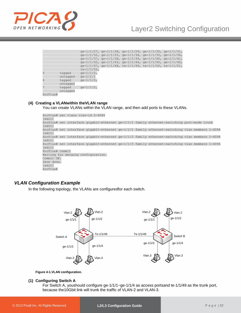
© 2012 Pica8 Inc. All © 2012 Pica8 Inc. All
Layer2 Switching Configuration
© 2013 Pica8 Inc. All Rights Reserved. L2/L3 Configuration Guide
P a g e | 52
ge-1/1/27, ge-1/1/28, ge-1/1/29, ge-1/1/30, ge-1/1/31,
ge-1/1/32, ge-1/1/33, ge-1/1/34, ge-1/1/35, ge-1/1/36,
ge-1/1/37, ge-1/1/38, ge-1/1/39, ge-1/1/40, ge-1/1/41,
ge-1/1/42, ge-1/1/43, ge-1/1/44, ge-1/1/45, ge-1/1/46,
ge-1/1/47, ge-1/1/48, te-1/1/49, te-1/1/50, te-1/1/51,
te-1/1/52,
5 tagged ge-1/1/2,
untagged ge-1/1/1
6 tagged ge-1/1/2,
untagged
7 tagged ge-1/1/2,
untagged
XorPlus#
(4) Creating a VLANwithin theVLAN range
You can create VLANs within the VLAN range, and then add ports to these VLANs.
XorPlus# set vlans vlan-id 2-4094
[edit]
XorPlus# set interface gigabit-ethernet ge-1/1/1 family ethernet-switching port-mode trunk
[edit]
XorPlus# set interface gigabit-ethernet ge-1/1/1 family ethernet-switching vlan members 1-4094
[edit]
XorPlus# set interface gigabit-ethernet ge-1/1/2 family ethernet-switching vlan members 1-4094
[edit]
XorPlus# set interface gigabit-ethernet ge-1/1/3 family ethernet-switching vlan members 1-4094
[edit]
XorPlus# commit
Waiting for merging configuration.
Commit OK.
Save done.
[edit]
XorPlus#
VLAN Configuration Example
In the following topology, the VLANs are configuredfor each switch.
Switch A Switch BTe-1/1/49 Te-1/1/49
ge-1/1/3 ge-1/1/4ge-1/1/3 ge-1/1/4
Vlan.2Vlan.2 Vlan.2 Vlan.2
Vlan.3Vlan.3Vlan.3Vlan.3
ge-1/1/1 ge-1/1/2 ge-1/1/1ge-1/1/2
Figure 4-1.VLAN configuration.
(1) Configuring Switch A
For Switch A, youshould configure ge-1/1/1~ge-1/1/4 as access portsand te-1/1/49 as the trunk port, because the10Gbit link will trunk the traffic of VLAN-2 and VLAN-3.
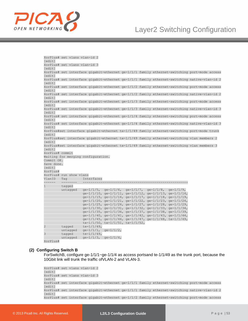
© 2012 Pica8 Inc. All © 2012 Pica8 Inc. All
Layer2 Switching Configuration
© 2013 Pica8 Inc. All Rights Reserved. L2/L3 Configuration Guide
P a g e | 53
XorPlus# set vlans vlan-id 2
[edit]
XorPlus# set vlans vlan-id 3
[edit]
XorPlus# set interface gigabit-ethernet ge-1/1/1 family ethernet-switching port-mode access
[edit]
XorPlus# set interface gigabit-ethernet ge-1/1/1 family ethernet-switching native-vlan-id 2
[edit]
XorPlus# set interface gigabit-ethernet ge-1/1/2 family ethernet-switching port-mode access
[edit]
XorPlus# set interface gigabit-ethernet ge-1/1/2 family ethernet-switching native-vlan-id 2
[edit]
XorPlus# set interface gigabit-ethernet ge-1/1/3 family ethernet-switching port-mode access
[edit]
XorPlus# set interface gigabit-ethernet ge-1/1/3 family ethernet-switching native-vlan-id 3
[edit]
XorPlus# set interface gigabit-ethernet ge-1/1/4 family ethernet-switching port-mode access
[edit]
XorPlus# set interface gigabit-ethernet ge-1/1/4 family ethernet-switching native-vlan-id 3
[edit]
XorPlus#set interface gigabit-ethernet te-1/1/49 family ethernet-switching port-mode trunk
[edit]
XorPlus#set interface gigabit-ethernet te-1/1/49 family ethernet-switching vlan members 2
[edit]
XorPlus#set interface gigabit-ethernet te-1/1/49 family ethernet-switching vlan members 3
[edit]
XorPlus# commit
Waiting for merging configuration.
Commit OK.
Save done.
[edit]
XorPlus#
XorPlus# run show vlans
VlanID Tag Interfaces
------ -------- ------------------------------------------------------
1 tagged
untagged ge-1/1/5, ge-1/1/6, ge-1/1/7, ge-1/1/8, ge-1/1/9,
ge-1/1/10, ge-1/1/11, ge-1/1/12, ge-1/1/13, ge-1/1/14,
ge-1/1/15, ge-1/1/16, ge-1/1/17, ge-1/1/18, ge-1/1/19,
ge-1/1/20, ge-1/1/21, ge-1/1/22, ge-1/1/23, ge-1/1/24,
ge-1/1/25, ge-1/1/26, ge-1/1/27, ge-1/1/28, ge-1/1/29,
ge-1/1/30, ge-1/1/31, ge-1/1/32, ge-1/1/33, ge-1/1/34,
ge-1/1/35, ge-1/1/36, ge-1/1/37, ge-1/1/38, ge-1/1/39,
ge-1/1/40, ge-1/1/41, ge-1/1/42, ge-1/1/43, ge-1/1/44,
ge-1/1/45, ge-1/1/46, ge-1/1/47, ge-1/1/48, te-1/1/49,
te-1/1/50, te-1/1/51, te-1/1/52,
2 tagged te-1/1/49,
untagged ge-1/1/1, ge-1/1/2,
3 tagged te-1/1/49,
untagged ge-1/1/3, ge-1/1/4,
XorPlus#
(2) Configuring Switch B ForSwitchB, configure ge-1/1/1~ge-1/1/4 as access portsand te-1/1/49 as the trunk port, because the 10Gbit link will trunk the traffic ofVLAN-2 and VLAN-3.
XorPlus# set vlans vlan-id 2
[edit]
XorPlus# set vlans vlan-id 3
[edit]
XorPlus# set interface gigabit-ethernet ge-1/1/1 family ethernet-switching port-mode access
[edit]
XorPlus# set interface gigabit-ethernet ge-1/1/1 family ethernet-switching native-vlan-id 2
[edit]
XorPlus# set interface gigabit-ethernet ge-1/1/2 family ethernet-switching port-mode access

© 2012 Pica8 Inc. All © 2012 Pica8 Inc. All
Layer2 Switching Configuration
© 2013 Pica8 Inc. All Rights Reserved. L2/L3 Configuration Guide
P a g e | 54
[edit]
XorPlus# set interface gigabit-ethernet ge-1/1/2 family ethernet-switching native-vlan-id 2
[edit]
XorPlus# set interface gigabit-ethernet ge-1/1/3 family ethernet-switching port-mode access
[edit]
XorPlus# set interface gigabit-ethernet ge-1/1/3 family ethernet-switching native-vlan-id 3
[edit]
XorPlus# set interface gigabit-ethernet ge-1/1/4 family ethernet-switching port-mode access
[edit]
XorPlus# set interface gigabit-ethernet ge-1/1/4 family ethernet-switching native-vlan-id 3
[edit]
XorPlus#set interface gigabit-ethernet te-1/1/49 family ethernet-switching port-mode trunk
[edit]
XorPlus#set interface gigabit-ethernet te-1/1/49 family ethernet-switching vlan members 2
[edit]
XorPlus#set interface gigabit-ethernet te-1/1/49 family ethernet-switching vlan members 3
[edit]
XorPlus# commit
Waiting for merging configuration.
Commit OK.
Save done.
[edit]
XorPlus#
XorPlus# run show vlans
VlanID Tag Interfaces
------ -------- ------------------------------------------------------
1 tagged
untagged ge-1/1/5, ge-1/1/6, ge-1/1/7, ge-1/1/8, ge-1/1/9,
ge-1/1/10, ge-1/1/11, ge-1/1/12, ge-1/1/13, ge-1/1/14,
ge-1/1/15, ge-1/1/16, ge-1/1/17, ge-1/1/18, ge-1/1/19,
ge-1/1/20, ge-1/1/21, ge-1/1/22, ge-1/1/23, ge-1/1/24,
ge-1/1/25, ge-1/1/26, ge-1/1/27, ge-1/1/28, ge-1/1/29,
ge-1/1/30, ge-1/1/31, ge-1/1/32, ge-1/1/33, ge-1/1/34,
ge-1/1/35, ge-1/1/36, ge-1/1/37, ge-1/1/38, ge-1/1/39,
ge-1/1/40, ge-1/1/41, ge-1/1/42, ge-1/1/43, ge-1/1/44,
ge-1/1/45, ge-1/1/46, ge-1/1/47, ge-1/1/48, te-1/1/49,
te-1/1/50, te-1/1/51, te-1/1/52,
2 tagged te-1/1/49,
untagged ge-1/1/1, ge-1/1/2,
3 tagged te-1/1/49,
untagged ge-1/1/3, ge-1/1/4,
Q-in-Q Basic Port Configuration
●Q-in-Q tunneling allows service providers on Ethernet access networks to extend a Layer 2 Ethernet connection between two customer sites. You can also use Q-in-Q tunneling to segregate or bundle customer traffic into fewer VLANs, or different VLANs, by adding another layer of 802.1Q tags.
●Q-in-Q tunneling is useful when customers have overlapping VLAN IDs, because the customer’s 802.1Q VLAN
tags are prependedby the service VLAN tag. The L2/L3implementation of Q-in-Q tunneling supports the IEEE 802.1ad standard.
●The Q-in-Q tunneling external mode belongs to basic Q-in-Q, while the Q-in-Q tunneling internal mode belongs
to selective Q-in-Q.
(1) Configuringthe Q-in-Q tunneling internal/external mode By default, Q-in-Q is disabled. You can enable it as shown below: XorPlus# set interface gigabit-ethernet ge-1/1/1 family ethernet-switching dot1q-tunneling
internal
[edit]
XorPlus# set interface gigabit-ethernet ge-1/1/2 family ethernet-switching dot1q-tunneling mode
external
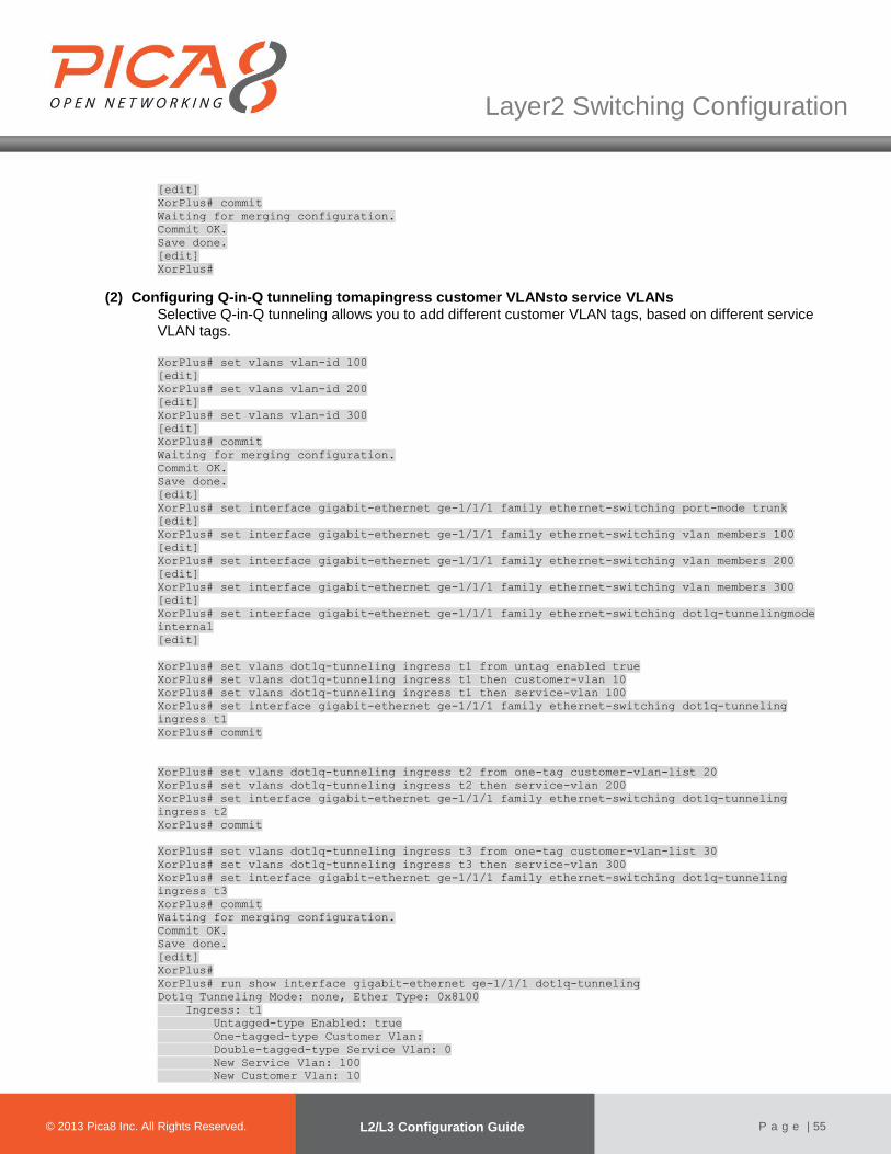
© 2012 Pica8 Inc. All © 2012 Pica8 Inc. All
Layer2 Switching Configuration
© 2013 Pica8 Inc. All Rights Reserved. L2/L3 Configuration Guide
P a g e | 55
[edit]
XorPlus# commit
Waiting for merging configuration.
Commit OK.
Save done.
[edit]
XorPlus#
(2) Configuring Q-in-Q tunneling tomapingress customer VLANsto service VLANs Selective Q-in-Q tunneling allows you to add different customer VLAN tags, based on different service VLAN tags. XorPlus# set vlans vlan-id 100
[edit]
XorPlus# set vlans vlan-id 200
[edit]
XorPlus# set vlans vlan-id 300
[edit]
XorPlus# commit
Waiting for merging configuration.
Commit OK.
Save done.
[edit]
XorPlus# set interface gigabit-ethernet ge-1/1/1 family ethernet-switching port-mode trunk
[edit]
XorPlus# set interface gigabit-ethernet ge-1/1/1 family ethernet-switching vlan members 100
[edit]
XorPlus# set interface gigabit-ethernet ge-1/1/1 family ethernet-switching vlan members 200
[edit]
XorPlus# set interface gigabit-ethernet ge-1/1/1 family ethernet-switching vlan members 300
[edit]
XorPlus# set interface gigabit-ethernet ge-1/1/1 family ethernet-switching dot1q-tunnelingmode
internal
[edit]
XorPlus# set vlans dot1q-tunneling ingress t1 from untag enabled true
XorPlus# set vlans dot1q-tunneling ingress t1 then customer-vlan 10
XorPlus# set vlans dot1q-tunneling ingress t1 then service-vlan 100
XorPlus# set interface gigabit-ethernet ge-1/1/1 family ethernet-switching dot1q-tunneling
ingress t1
XorPlus# commit
XorPlus# set vlans dot1q-tunneling ingress t2 from one-tag customer-vlan-list 20
XorPlus# set vlans dot1q-tunneling ingress t2 then service-vlan 200
XorPlus# set interface gigabit-ethernet ge-1/1/1 family ethernet-switching dot1q-tunneling
ingress t2
XorPlus# commit
XorPlus# set vlans dot1q-tunneling ingress t3 from one-tag customer-vlan-list 30
XorPlus# set vlans dot1q-tunneling ingress t3 then service-vlan 300
XorPlus# set interface gigabit-ethernet ge-1/1/1 family ethernet-switching dot1q-tunneling
ingress t3
XorPlus# commit
Waiting for merging configuration.
Commit OK.
Save done.
[edit]
XorPlus#
XorPlus# run show interface gigabit-ethernet ge-1/1/1 dot1q-tunneling
Dot1q Tunneling Mode: none, Ether Type: 0x8100
Ingress: t1
Untagged-type Enabled: true
One-tagged-type Customer Vlan:
Double-tagged-type Service Vlan: 0
New Service Vlan: 100
New Customer Vlan: 10

© 2012 Pica8 Inc. All © 2012 Pica8 Inc. All
Layer2 Switching Configuration
© 2013 Pica8 Inc. All Rights Reserved. L2/L3 Configuration Guide
P a g e | 56
Ingress: t2
Untagged-type Enabled: false
One-tagged-type Customer Vlan: 20
Double-tagged-type Service Vlan: 0
New Service Vlan: 200
New Customer Vlan: 0
Ingress: t3
Untagged-type Enabled: false
One-tagged-type Customer Vlan: 30
Double-tagged-type Service Vlan: 0
New Service Vlan: 300
New Customer Vlan: 0
XorPlus#
(3) Configuring Q-in-Q tunneling egress pop service VLANs Selective Q-in-Q tunneling allows you to delete different customer VLAN tags, based on different service VLAN tags.
XorPlus# set vlans vlan-id 100
[edit]
XorPlus# set vlans vlan-id 200
[edit]
XorPlus# set vlans vlan-id 300
[edit]
XorPlus# commit
Waiting for merging configuration.
Commit OK.
Save done.
[edit]
XorPlus# set interface gigabit-ethernet ge-1/1/1 family ethernet-switching port-mode trunk
[edit]
XorPlus# set interface gigabit-ethernet ge-1/1/1 family ethernet-switching vlan members 100
[edit]
XorPlus# set interface gigabit-ethernet ge-1/1/1 family ethernet-switching vlan members 200
[edit]
XorPlus# set interface gigabit-ethernet ge-1/1/1 family ethernet-switching vlan members 300
[edit]
XorPlus# set interface gigabit-ethernet ge-1/1/1 family ethernet-switching native-vlan-id 100
[edit]
XorPlus# set interface gigabit-ethernet ge-1/1/1 family ethernet-switching dot1q-tunneling mode
internal
XorPlus# commit
XorPlus# set vlans dot1q-tunneling egress t1 from customer-vlan 10
XorPlus# set vlans dot1q-tunneling egress t1 from service-vlan 100
XorPlus# set vlans dot1q-tunneling egress t1 then action none
XorPlus# set interface gigabit-ethernet ge-1/1/1 family ethernet-switching dot1q-tunneling
egress t1
XorPlus# commit
XorPlus# set vlans dot1q-tunneling egress t2 from customer-vlan 20
XorPlus# set vlans dot1q-tunneling egress t2 from service-vlan 200
XorPlus# set vlans dot1q-tunneling egress t2 then action one
XorPlus# set interface gigabit-ethernet ge-1/1/1 family ethernet-switching dot1q-tunneling
egress t2
XorPlus# commit
XorPlus# set vlans dot1q-tunneling egress t3 from customer-vlan 30
XorPlus# set vlans dot1q-tunneling egress t3 from service-vlan 300
XorPlus# set vlans dot1q-tunneling egress t3 then action one
XorPlus# set interface gigabit-ethernet ge-1/1/1 family ethernet-switching dot1q-tunneling
egress t3
XorPlus# commit
Waiting for merging configuration.
Commit OK.
Save done.
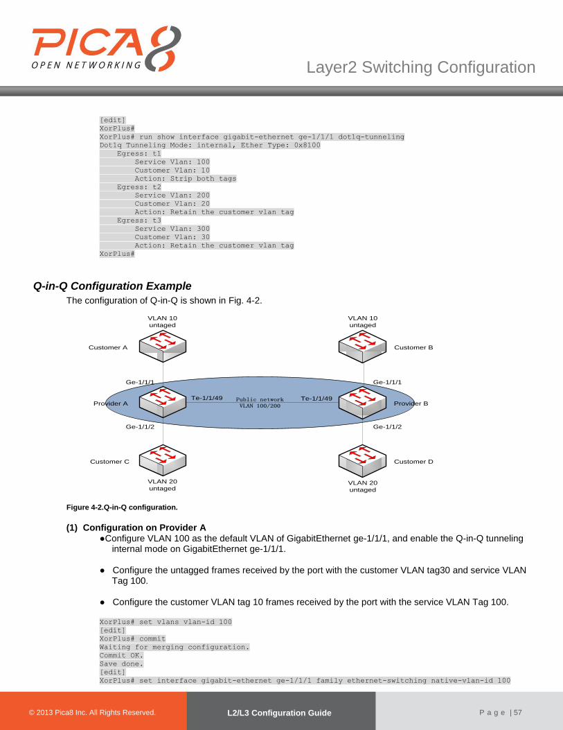
© 2012 Pica8 Inc. All © 2012 Pica8 Inc. All
Layer2 Switching Configuration
© 2013 Pica8 Inc. All Rights Reserved. L2/L3 Configuration Guide
P a g e | 57
[edit]
XorPlus#
XorPlus# run show interface gigabit-ethernet ge-1/1/1 dot1q-tunneling
Dot1q Tunneling Mode: internal, Ether Type: 0x8100
Egress: t1
Service Vlan: 100
Customer Vlan: 10
Action: Strip both tags
Egress: t2
Service Vlan: 200
Customer Vlan: 20
Action: Retain the customer vlan tag
Egress: t3
Service Vlan: 300
Customer Vlan: 30
Action: Retain the customer vlan tag
XorPlus#
Q-in-Q Configuration Example
The configuration of Q-in-Q is shown in Fig. 4-2.
Public networkVLAN 100/200Provider A
Te-1/1/49 Te-1/1/49Provider B
Customer C Customer D
Customer A Customer B
VLAN 20
untaged
VLAN 10
untaged
VLAN 10
untaged
VLAN 20
untaged
Ge-1/1/1
Ge-1/1/2
Ge-1/1/1
Ge-1/1/2
Figure 4-2.Q-in-Q configuration.
(1) Configuration on Provider A
●Configure VLAN 100 as the default VLAN of GigabitEthernet ge-1/1/1, and enable the Q-in-Q tunneling internal mode on GigabitEthernet ge-1/1/1.
● Configure the untagged frames received by the port with the customer VLAN tag30 and service VLAN
Tag 100.
● Configure the customer VLAN tag 10 frames received by the port with the service VLAN Tag 100.
XorPlus# set vlans vlan-id 100
[edit]
XorPlus# commit
Waiting for merging configuration.
Commit OK.
Save done.
[edit]
XorPlus# set interface gigabit-ethernet ge-1/1/1 family ethernet-switching native-vlan-id 100

© 2012 Pica8 Inc. All © 2012 Pica8 Inc. All
Layer2 Switching Configuration
© 2013 Pica8 Inc. All Rights Reserved. L2/L3 Configuration Guide
P a g e | 58
[edit]
XorPlus# set vlans dot1q-tunneling ingress t1 from untag enabled true
XorPlus# set vlans dot1q-tunneling ingress t1 then customer-vlan 30
XorPlus# set vlans dot1q-tunneling ingress t1 then service-vlan 100
XorPlus# set interface gigabit-ethernet ge-1/1/1 family ethernet-switching dot1q-tunneling
ingress t1
XorPlus# commit
XorPlus# set vlans dot1q-tunneling ingress t2 from one-tag customer-vlan-list 10
XorPlus# set vlans dot1q-tunneling ingress t2 then service-vlan 100
XorPlus# set interface gigabit-ethernet ge-1/1/1 family ethernet-switching dot1q-tunneling
ingress t2
XorPlus# commit
XorPlus# set vlans dot1q-tunneling egress t3 from customer-vlan 10
XorPlus# set vlans dot1q-tunneling egress t3 from service-vlan 100
XorPlus# set vlans dot1q-tunneling egress t3 then action one
XorPlus# set interface gigabit-ethernet ge-1/1/1 family ethernet-switching dot1q-tunneling
egress t3
XorPlus# commit
XorPlus# set vlans dot1q-tunneling egress t4 from customer-vlan 30
XorPlus# set vlans dot1q-tunneling egress t4 from service-vlan 100
XorPlus# set vlans dot1q-tunneling egress t4 then action none
XorPlus# set interface gigabit-ethernet ge-1/1/1 family ethernet-switching dot1q-tunneling
egress t4
XorPlus# set interface gigabit-ethernet ge-1/1/1 family ethernet-switching dot1q-tunneling mode
internal
XorPlus# commit
Waiting for merging configuration.
Commit OK.
Save done.
[edit]
XorPlus# run show interface gigabit-ethernet ge-1/1/1 dot1q-tunneling
Dot1q Tunneling Mode: internal, Ether Type: 0x8100
Ingress: t1
Untagged-type Enabled: true
One-tagged-type Customer Vlan:
Double-tagged-type Service Vlan: 0
New Service Vlan: 100
New Customer Vlan: 30
Ingress: t2
Untagged-type Enabled: false
One-tagged-type Customer Vlan: 10
Double-tagged-type Service Vlan: 0
New Service Vlan: 100
New Customer Vlan: 0
Egress: t3
Service Vlan: 100
Customer Vlan: 10
Action: Retain the customer vlan tag
Egress: t4
Service Vlan: 100
Customer Vlan: 30
Action: Strip both tags
XorPlus#
● Configure VLAN 200 as the default VLAN of GigabitEthernet ge-1/1/2, and enable the Q-in-Q tunneling internal mode on GigabitEthernet ge-1/1/2.
● Configure the untagged frames received by the port with the customer VLAN tag30 and service VLAN
Tag 200.
● Configure the customer VLAN tag20frames received by the port with the service VLAN Tag 200.
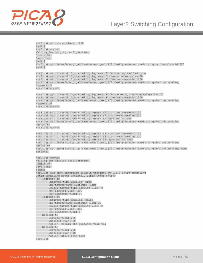
© 2012 Pica8 Inc. All © 2012 Pica8 Inc. All
Layer2 Switching Configuration
© 2013 Pica8 Inc. All Rights Reserved. L2/L3 Configuration Guide
P a g e | 59
XorPlus# set vlans vlan-id 200
[edit]
XorPlus# commit
Waiting for merging configuration.
Commit OK.
Save done.
[edit]
XorPlus# set interface gigabit-ethernet ge-1/1/2 family ethernet-switching native-vlan-id 200
[edit]
XorPlus# set vlans dot1q-tunneling ingress t5 from untag enabled true
XorPlus# set vlans dot1q-tunneling ingress t5 then customer-vlan 30
XorPlus# set vlans dot1q-tunneling ingress t5 then service-vlan 200
XorPlus# set interface gigabit-ethernet ge-1/1/2 family ethernet-switching dot1q-tunneling
ingress t5
XorPlus# commit
XorPlus# set vlans dot1q-tunneling ingress t6 from one-tag customer-vlan-list 20
XorPlus# set vlans dot1q-tunneling ingress t6 then service-vlan 200
XorPlus# set interface gigabit-ethernet ge-1/1/2 family ethernet-switching dot1q-tunneling
ingress t6
XorPlus# commit
XorPlus# set vlans dot1q-tunneling egress t7 from customer-vlan 20
XorPlus# set vlans dot1q-tunneling egress t7 from service-vlan 200
XorPlus# set vlans dot1q-tunneling egress t7 then action one
XorPlus# set interface gigabit-ethernet ge-1/1/2 family ethernet-switching dot1q-tunneling
egress t7
XorPlus# commit
XorPlus# set vlans dot1q-tunneling egress t8 from customer-vlan 30
XorPlus# set vlans dot1q-tunneling egress t8 from service-vlan 200
XorPlus# set vlans dot1q-tunneling egress t8 then action none
XorPlus# set interface gigabit-ethernet ge-1/1/2 family ethernet-switching dot1q-tunneling
egress t8
XorPlus# set interface gigabit-ethernet ge-1/1/2 family ethernet-switching dot1q-tunneling mode
internal
XorPlus# commit
Waiting for merging configuration.
Commit OK.
Save done.
[edit]
XorPlus# run show interface gigabit-ethernet ge-1/1/2 dot1q-tunneling
Dot1q Tunneling Mode: internal, Ether Type: 0x8100
Ingress: t5
Untagged-type Enabled: true
One-tagged-type Customer Vlan:
Double-tagged-type Service Vlan: 0
New Service Vlan: 200
New Customer Vlan: 30
Ingress: t6
Untagged-type Enabled: false
One-tagged-type Customer Vlan: 20
Double-tagged-type Service Vlan: 0
New Service Vlan: 200
New Customer Vlan: 0
Egress: t7
Service Vlan: 200
Customer Vlan: 20
Action: Retain the customer vlan tag
Egress: t8
Service Vlan: 200
Customer Vlan: 30
Action: Strip both tags
XorPlus#

© 2012 Pica8 Inc. All © 2012 Pica8 Inc. All
Layer2 Switching Configuration
© 2013 Pica8 Inc. All Rights Reserved. L2/L3 Configuration Guide
P a g e | 60
Configure VLAN 100/200 as the trunk port of GigabitEthernet te-1/1/49, and enable the Q-in-Q tunneling internal mode.
XorPlus# set interface gigabit-ethernet te-1/1/49 family ethernet-switching port-mode trunk
[edit]
XorPlus# set interface gigabit-ethernet te-1/1/49 family ethernet-switching vlan members 100
[edit]
XorPlus# set interface gigabit-ethernet te-1/1/49 family ethernet-switching vlan members 200
[edit]
XorPlus# set interface gigabit-ethernet te-1/1/49 family ethernet-switching dot1q-tunneling
modeinternal
[edit]
XorPlus# commit
Waiting for merging configuration.
Commit OK.
Save done.
[edit]
XorPlus# run show interface gigabit-ethernet te-1/1/49 dot1q-tunneling
Dot1q Tunneling Mode: internal, Ether Type: 0x8100
XorPlus#
(2) Configuration on Provider B ● Configure VLAN 100 as the default VLAN of GigabitEthernet ge-1/1/1, and enable the Q-in-Q
tunneling internal mode on GigabitEthernet ge-1/1/1.
● Configure the untagged frames received by the port with the customer VLAN tag30 and service VLAN Tag 100.
● Configure the customer VLAN tag 10 frames received by the port with the service VLAN Tag 100. XorPlus# set vlans vlan-id 100
[edit]
XorPlus# commit
Waiting for merging configuration.
Commit OK.
Save done.
[edit]
XorPlus# set interface gigabit-ethernet ge-1/1/1 family ethernet-switching native-vlan-id 100
[edit]
XorPlus# set vlans dot1q-tunneling ingress t1 from untag enabled true
XorPlus# set vlans dot1q-tunneling ingress t1 then customer-vlan 30
XorPlus# set vlans dot1q-tunneling ingress t1 then service-vlan 100
XorPlus# set interface gigabit-ethernet ge-1/1/1 family ethernet-switching dot1q-tunneling
ingress t1
XorPlus# commit
XorPlus# set vlans dot1q-tunneling ingress t2 from one-tag customer-vlan-list 10
XorPlus# set vlans dot1q-tunneling ingress t2 then service-vlan 100
XorPlus# set interface gigabit-ethernet ge-1/1/1 family ethernet-switching dot1q-tunneling
ingress t2
XorPlus# commit
XorPlus# set vlans dot1q-tunneling egress t3 from customer-vlan 10
XorPlus# set vlans dot1q-tunneling egress t3 from service-vlan 100
XorPlus# set vlans dot1q-tunneling egress t3 then action one
XorPlus# set interface gigabit-ethernet ge-1/1/1 family ethernet-switching dot1q-tunneling
egress t3
XorPlus# commit
XorPlus# set vlans dot1q-tunneling egress t4 from customer-vlan 30
XorPlus# set vlans dot1q-tunneling egress t4 from service-vlan 100

© 2012 Pica8 Inc. All © 2012 Pica8 Inc. All
Layer2 Switching Configuration
© 2013 Pica8 Inc. All Rights Reserved. L2/L3 Configuration Guide
P a g e | 61
XorPlus# set vlans dot1q-tunneling egress t4 then action none
XorPlus# set interface gigabit-ethernet ge-1/1/1 family ethernet-switching dot1q-tunneling
egress t4
XorPlus# set interface gigabit-ethernet ge-1/1/1 family ethernet-switching dot1q-tunneling mode
internal
XorPlus# commit
Waiting for merging configuration.
Commit OK.
Save done.
[edit]
XorPlus# run show interface gigabit-ethernet ge-1/1/1 dot1q-tunneling
Dot1q Tunneling Mode: internal, Ether Type: 0x8100
Ingress: t1
Untagged-type Enabled: true
One-tagged-type Customer Vlan:
Double-tagged-type Service Vlan: 0
New Service Vlan: 100
New Customer Vlan: 30
Ingress: t2
Untagged-type Enabled: false
One-tagged-type Customer Vlan: 10
Double-tagged-type Service Vlan: 0
New Service Vlan: 100
New Customer Vlan: 0
Egress: t3
Service Vlan: 100
Customer Vlan: 10
Action: Retain the customer vlan tag
Egress: t4
Service Vlan: 100
Customer Vlan: 30
Action: Strip both tags
XorPlus#
●Configure VLAN 200 as the default VLAN of Gigabit Ethernet ge-1/1/2, and enable the Q-in-Q tunneling
internal mode on Gigabit Ethernet 1/1/2.
● Configure the untagged frames received by the port with the customer VLAN tag 30 and service VLAN Tag 200.
● Configure the customer VLAN tag 20 frames received by the port with the service VLAN Tag 200.
XorPlus# set vlans vlan-id 200
[edit]
XorPlus# commit
Waiting for merging configuration.
Commit OK.
Save done.
[edit]
XorPlus# set interface gigabit-ethernet ge-1/1/2 family ethernet-switching native-vlan-id 200
[edit]
XorPlus# set vlans dot1q-tunneling ingress t5 from untag enabled true
XorPlus# set vlans dot1q-tunneling ingress t5 then customer-vlan 30
XorPlus# set vlans dot1q-tunneling ingress t5 then service-vlan 200
XorPlus# set interface gigabit-ethernet ge-1/1/2 family ethernet-switching dot1q-tunneling
ingress t5
XorPlus# commit
XorPlus# set vlans dot1q-tunneling ingress t6 from one-tag customer-vlan-list 20
XorPlus# set vlans dot1q-tunneling ingress t6 then service-vlan 200
XorPlus# set interface gigabit-ethernet ge-1/1/2 family ethernet-switching dot1q-tunneling
ingress t6
XorPlus# commit
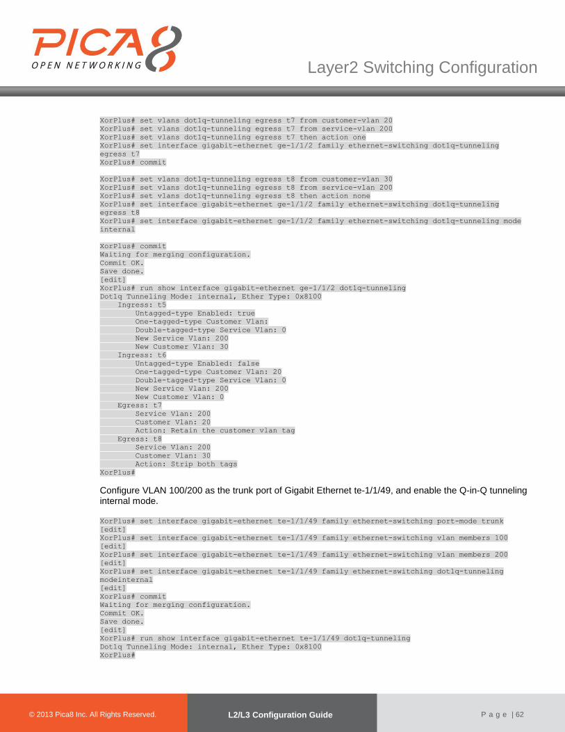
© 2012 Pica8 Inc. All © 2012 Pica8 Inc. All
Layer2 Switching Configuration
© 2013 Pica8 Inc. All Rights Reserved. L2/L3 Configuration Guide
P a g e | 62
XorPlus# set vlans dot1q-tunneling egress t7 from customer-vlan 20
XorPlus# set vlans dot1q-tunneling egress t7 from service-vlan 200
XorPlus# set vlans dot1q-tunneling egress t7 then action one
XorPlus# set interface gigabit-ethernet ge-1/1/2 family ethernet-switching dot1q-tunneling
egress t7
XorPlus# commit
XorPlus# set vlans dot1q-tunneling egress t8 from customer-vlan 30
XorPlus# set vlans dot1q-tunneling egress t8 from service-vlan 200
XorPlus# set vlans dot1q-tunneling egress t8 then action none
XorPlus# set interface gigabit-ethernet ge-1/1/2 family ethernet-switching dot1q-tunneling
egress t8
XorPlus# set interface gigabit-ethernet ge-1/1/2 family ethernet-switching dot1q-tunneling mode
internal
XorPlus# commit
Waiting for merging configuration.
Commit OK.
Save done.
[edit]
XorPlus# run show interface gigabit-ethernet ge-1/1/2 dot1q-tunneling
Dot1q Tunneling Mode: internal, Ether Type: 0x8100
Ingress: t5
Untagged-type Enabled: true
One-tagged-type Customer Vlan:
Double-tagged-type Service Vlan: 0
New Service Vlan: 200
New Customer Vlan: 30
Ingress: t6
Untagged-type Enabled: false
One-tagged-type Customer Vlan: 20
Double-tagged-type Service Vlan: 0
New Service Vlan: 200
New Customer Vlan: 0
Egress: t7
Service Vlan: 200
Customer Vlan: 20
Action: Retain the customer vlan tag
Egress: t8
Service Vlan: 200
Customer Vlan: 30
Action: Strip both tags
XorPlus#
Configure VLAN 100/200 as the trunk port of Gigabit Ethernet te-1/1/49, and enable the Q-in-Q tunneling internal mode. XorPlus# set interface gigabit-ethernet te-1/1/49 family ethernet-switching port-mode trunk
[edit]
XorPlus# set interface gigabit-ethernet te-1/1/49 family ethernet-switching vlan members 100
[edit]
XorPlus# set interface gigabit-ethernet te-1/1/49 family ethernet-switching vlan members 200
[edit]
XorPlus# set interface gigabit-ethernet te-1/1/49 family ethernet-switching dot1q-tunneling
modeinternal
[edit]
XorPlus# commit
Waiting for merging configuration.
Commit OK.
Save done.
[edit]
XorPlus# run show interface gigabit-ethernet te-1/1/49 dot1q-tunneling
Dot1q Tunneling Mode: internal, Ether Type: 0x8100
XorPlus#
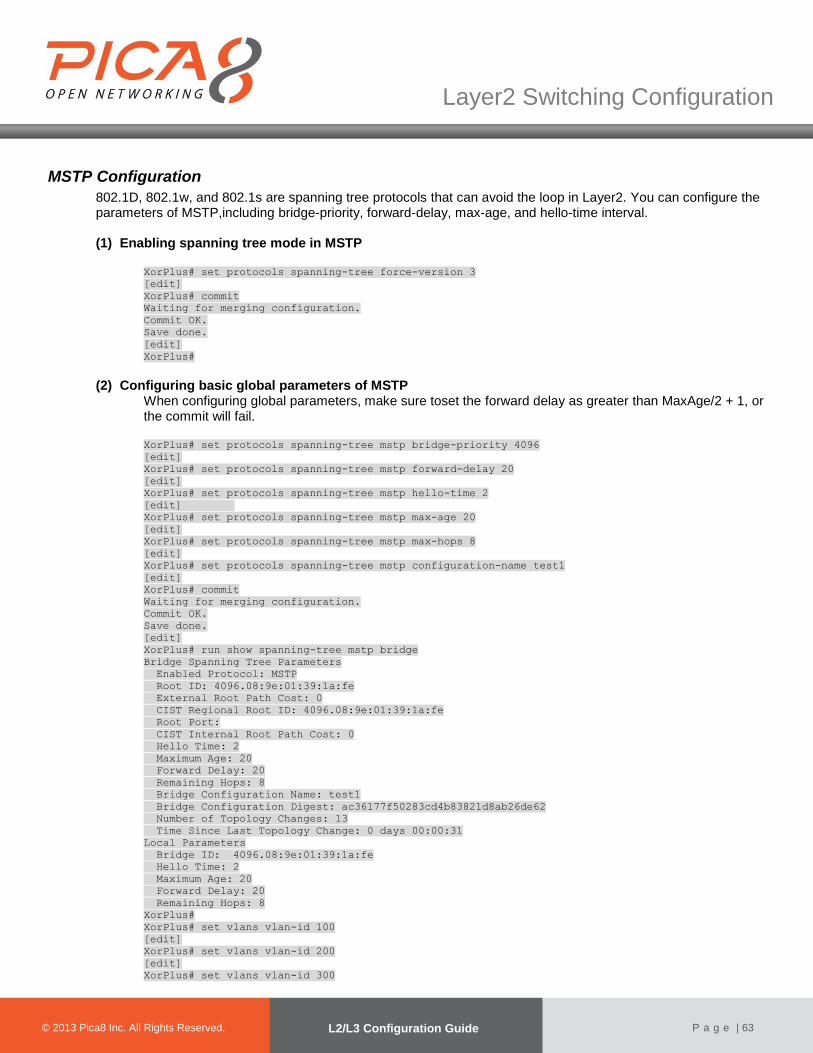
© 2012 Pica8 Inc. All © 2012 Pica8 Inc. All
Layer2 Switching Configuration
© 2013 Pica8 Inc. All Rights Reserved. L2/L3 Configuration Guide
P a g e | 63
MSTP Configuration
802.1D, 802.1w, and 802.1s are spanning tree protocols that can avoid the loop in Layer2. You can configure the parameters of MSTP,including bridge-priority, forward-delay, max-age, and hello-time interval.
(1) Enabling spanning tree mode in MSTP
XorPlus# set protocols spanning-tree force-version 3
[edit]
XorPlus# commit
Waiting for merging configuration.
Commit OK.
Save done.
[edit]
XorPlus#
(2) Configuring basic global parameters of MSTP
When configuring global parameters, make sure toset the forward delay as greater than MaxAge/2 + 1, or the commit will fail. XorPlus# set protocols spanning-tree mstp bridge-priority 4096
[edit]
XorPlus# set protocols spanning-tree mstp forward-delay 20
[edit]
XorPlus# set protocols spanning-tree mstp hello-time 2
[edit]
XorPlus# set protocols spanning-tree mstp max-age 20
[edit]
XorPlus# set protocols spanning-tree mstp max-hops 8
[edit]
XorPlus# set protocols spanning-tree mstp configuration-name test1
[edit]
XorPlus# commit
Waiting for merging configuration.
Commit OK.
Save done.
[edit]
XorPlus# run show spanning-tree mstp bridge
Bridge Spanning Tree Parameters
Enabled Protocol: MSTP
Root ID: 4096.08:9e:01:39:1a:fe
External Root Path Cost: 0
CIST Regional Root ID: 4096.08:9e:01:39:1a:fe
Root Port:
CIST Internal Root Path Cost: 0
Hello Time: 2
Maximum Age: 20
Forward Delay: 20
Remaining Hops: 8
Bridge Configuration Name: test1
Bridge Configuration Digest: ac36177f50283cd4b83821d8ab26de62
Number of Topology Changes: 13
Time Since Last Topology Change: 0 days 00:00:31
Local Parameters
Bridge ID: 4096.08:9e:01:39:1a:fe
Hello Time: 2
Maximum Age: 20
Forward Delay: 20
Remaining Hops: 8
XorPlus#
XorPlus# set vlans vlan-id 100
[edit]
XorPlus# set vlans vlan-id 200
[edit]
XorPlus# set vlans vlan-id 300

© 2012 Pica8 Inc. All © 2012 Pica8 Inc. All
Layer2 Switching Configuration
© 2013 Pica8 Inc. All Rights Reserved. L2/L3 Configuration Guide
P a g e | 64
[edit]
XorPlus# set vlans vlan-id 400
[edit]
XorPlus# commit
Waiting for merging configuration.
Commit OK.
Save done.
[edit]
XorPlus# set protocols spanning-tree mstp msti 1
[edit]
XorPlus# set protocols spanning-tree mstp msti 2
[edit]
XorPlus# commit
Waiting for merging configuration.
Commit OK.
Save done.
[edit]
XorPlus# set protocols spanning-tree mstp msti 1 vlan 100
[edit]
XorPlus# set protocols spanning-tree mstp msti 1 vlan 200
[edit]
XorPlus# set protocols spanning-tree mstp msti 2 vlan 300
[edit]
XorPlus# set protocols spanning-tree mstp msti 2 vlan 400
[edit]
XorPlus# commit
Waiting for merging configuration.
Commit OK.
Save done.
[edit]
XorPlus#
XorPlus# run show spanning-tree mstp bridge
Bridge Spanning Tree Parameters
Enabled Protocol: MSTP
Root ID: 4096.08:9e:01:39:1a:fe
External Root Path Cost: 0
CIST Regional Root ID: 4096.08:9e:01:39:1a:fe
Root Port:
CIST Internal Root Path Cost: 0
Hello Time: 2
Maximum Age: 20
Forward Delay: 20
Remaining Hops: 8
Bridge Configuration Name: test1
Bridge Configuration Digest: 8b5d98ca042bad0d7fa5f18744f4755d
Msti 1 Member VLANs:
100, 200,
Msti 2 Member VLANs:
300, 400,
Number of Topology Changes: 14
Time Since Last Topology Change: 0 days 00:02:49
Local Parameters
Bridge ID: 4096.08:9e:01:39:1a:fe
Hello Time: 2
Maximum Age: 20
Forward Delay: 20
Remaining Hops: 8
XorPlus#
(3) Configuring MSTP interface parameters XorPlus# set protocols spanning-tree mstp interface ge-1/1/1 external-path-cost 30000
[edit]
XorPlus# set protocols spanning-tree mstp interface ge-1/1/1 internal-path-cost 10000
[edit]
XorPlus# set protocols spanning-tree mstp interface ge-1/1/1 edge true
[edit]

© 2012 Pica8 Inc. All © 2012 Pica8 Inc. All
Layer2 Switching Configuration
© 2013 Pica8 Inc. All Rights Reserved. L2/L3 Configuration Guide
P a g e | 65
XorPlus# set protocols spanning-tree mstp interface ge-1/1/1 mode point-to-point
[edit]
XorPlus# set protocols spanning-tree mstp interface ge-1/1/1 port-priority 100
[edit]
XorPlus# commit
Waiting for merging configuration.
Commit OK.
Save done.
[edit]
XorPlus# run show spanning-tree mstp interface
Spanning Tree Interface Parameters for Instance 0
Interface Port ID Designated Designated Bridge Ext Port Int Port State
Role
Port ID ID Cost Cost
---------- --------- ---------- ----------------------- --------- --------- ---------- ---
---
ge-1/1/1 96.1 96.1 8192.08:9e:01:39:1a:fe 30000 10000 FORWARDING
EDGE
(4) Configuring the BPDU Filter The BPDU filter prevents the bridge from using BPDUs for STP calculations. Theswitch will then ignore any BPDUs that it receives.
XorPlus# set protocols spanning-tree mstp interface ge-1/1/1 bpdu-filter true
[edit]
XorPlus# commit
Waiting for merging configuration.
Commit OK.
Save done.
[edit]
XorPlus#
(5) Configuring BPDU root guard If a switch port receives a higher bridge-priority BPDU, it will ignore the BPDU and keep the current root-bridge as the root-bridge.
XorPlus# set protocols spanning-tree mstp interface ge-1/1/1 root-guard true
[edit]
XorPlus# commit
Waiting for merging configuration.
Commit OK.
Save done.
[edit]
XorPlus#
(6) Configuring BPDU TCN-guard When a port is configured with TCN-guard, the port does not process and propagate any topological change-related information received on the configured port. XorPlus# set protocols spanning-tree mstp interface ge-1/1/1 tcn-guard true
[edit]
XorPlus# commit
Waiting for merging configuration.
Commit OK.
Save done.
[edit]
XorPlus#
(7) Disabling/enabling MSTP If you disable MSTP, the port will stay in forwarding statusand cease to send BPDUs.
XorPlus# set protocols spanning-tree enable false
[edit]
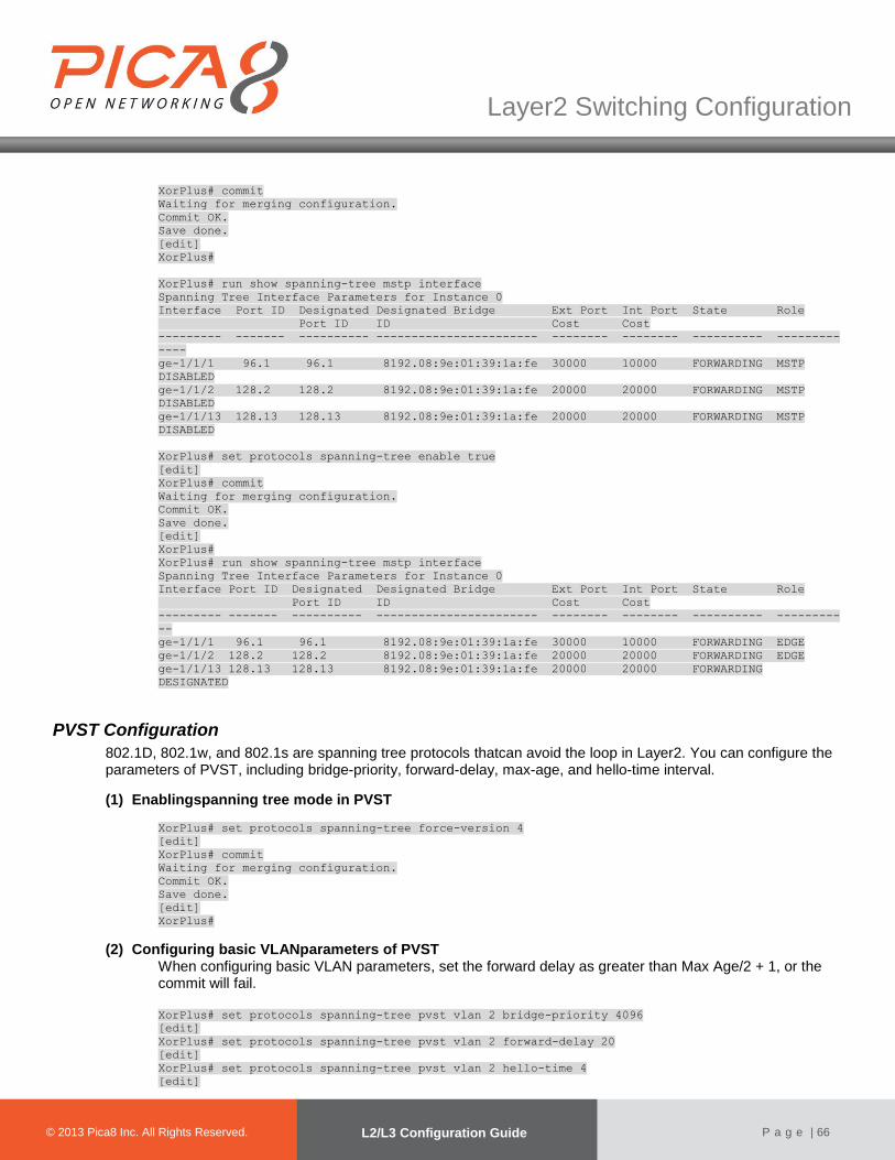
© 2012 Pica8 Inc. All © 2012 Pica8 Inc. All
Layer2 Switching Configuration
© 2013 Pica8 Inc. All Rights Reserved. L2/L3 Configuration Guide
P a g e | 66
XorPlus# commit
Waiting for merging configuration.
Commit OK.
Save done.
[edit]
XorPlus#
XorPlus# run show spanning-tree mstp interface
Spanning Tree Interface Parameters for Instance 0
Interface Port ID Designated Designated Bridge Ext Port Int Port State Role
Port ID ID Cost Cost
--------- ------- ---------- ----------------------- -------- -------- ---------- ---------
----
ge-1/1/1 96.1 96.1 8192.08:9e:01:39:1a:fe 30000 10000 FORWARDING MSTP
DISABLED
ge-1/1/2 128.2 128.2 8192.08:9e:01:39:1a:fe 20000 20000 FORWARDING MSTP
DISABLED
ge-1/1/13 128.13 128.13 8192.08:9e:01:39:1a:fe 20000 20000 FORWARDING MSTP
DISABLED
XorPlus# set protocols spanning-tree enable true
[edit]
XorPlus# commit
Waiting for merging configuration.
Commit OK.
Save done.
[edit]
XorPlus#
XorPlus# run show spanning-tree mstp interface
Spanning Tree Interface Parameters for Instance 0
Interface Port ID Designated Designated Bridge Ext Port Int Port State Role
Port ID ID Cost Cost
--------- ------- ---------- ----------------------- -------- -------- ---------- ---------
--
ge-1/1/1 96.1 96.1 8192.08:9e:01:39:1a:fe 30000 10000 FORWARDING EDGE
ge-1/1/2 128.2 128.2 8192.08:9e:01:39:1a:fe 20000 20000 FORWARDING EDGE
ge-1/1/13 128.13 128.13 8192.08:9e:01:39:1a:fe 20000 20000 FORWARDING
DESIGNATED
PVST Configuration
802.1D, 802.1w, and 802.1s are spanning tree protocols thatcan avoid the loop in Layer2. You can configure the parameters of PVST, including bridge-priority, forward-delay, max-age, and hello-time interval.
(1) Enablingspanning tree mode in PVST
XorPlus# set protocols spanning-tree force-version 4
[edit]
XorPlus# commit
Waiting for merging configuration.
Commit OK.
Save done.
[edit]
XorPlus#
(2) Configuring basic VLANparameters of PVST When configuring basic VLAN parameters, set the forward delay as greater than Max Age/2 + 1, or the commit will fail.
XorPlus# set protocols spanning-tree pvst vlan 2 bridge-priority 4096
[edit]
XorPlus# set protocols spanning-tree pvst vlan 2 forward-delay 20
[edit]
XorPlus# set protocols spanning-tree pvst vlan 2 hello-time 4
[edit]

© 2012 Pica8 Inc. All © 2012 Pica8 Inc. All
Layer2 Switching Configuration
© 2013 Pica8 Inc. All Rights Reserved. L2/L3 Configuration Guide
P a g e | 67
XorPlus# set protocols spanning-tree pvst vlan 2 max-age 30
[edit]
XorPlus# commit
Waiting for merging configuration.
Commit OK.
Save done.
[edit]
XorPlus#
XorPlus# run show spanning-tree pvst bridge vlan 2
PVST Bridge Parameters for VLAN 2
Root Bridge: 4098.08:9e:01:61:65:71
Root Cost: 0
Root Port:
Hello Time: 4
Max Age: 30
Forward Delay: 20
Time Since Last Topology Change: 0 days 00:02:55
Local Parameters
Bridge ID: 4098.08:9e:01:61:65:71
Hello Time: 4
Maximum Age: 30
Forward Delay: 20
(3) Configuring PVST interface parameters XorPlus# set protocols spanning-tree pvst vlan 2 interface ge-1/1/1 path-cost 555555
[edit]
XorPlus# set protocols spanning-tree pvst vlan 2 interface ge-1/1/1 port-priority 200
[edit]
XorPlus# commit
Waiting for merging configuration.
Commit OK.
Save done.
[edit]
XorPlus# run show spanning-tree pvst interface vlan 2
Rapid PVST+ Spanning Tree Interface Status for VLAN 2
Interface Port ID Designated Designated Bridge Port Cost State Role
Port ID ID
---------- --------- ---------- ----------------------- --------- ---------- --------------
-
ge-1/1/1 192.1 192.1 4098.08:9e:01:61:65:71 555555 FORWARDING EDGE
(4) Configuring the interface mode You can configure the interface mode as point-to-point or shared.
XorPlus# set protocols spanning-tree pvst interface ge-1/1/1 mode point-to-point
[edit]
XorPlus# commit
Waiting for merging configuration.
Commit OK.
Save done.
[edit]
XorPlus# set protocols spanning-tree pvst interface ge-1/1/1 mode shared
[edit]
XorPlus# commit
Waiting for merging configuration.
Commit OK.
Save done.
[edit]
XorPlus#
(5) Disabling/enabling PVST on one VLAN You can disable or enable the spanning tree protocol PVST on a singledesignated VLAN.
XorPlus# set protocols spanning-tree pvst vlan 2 enable false
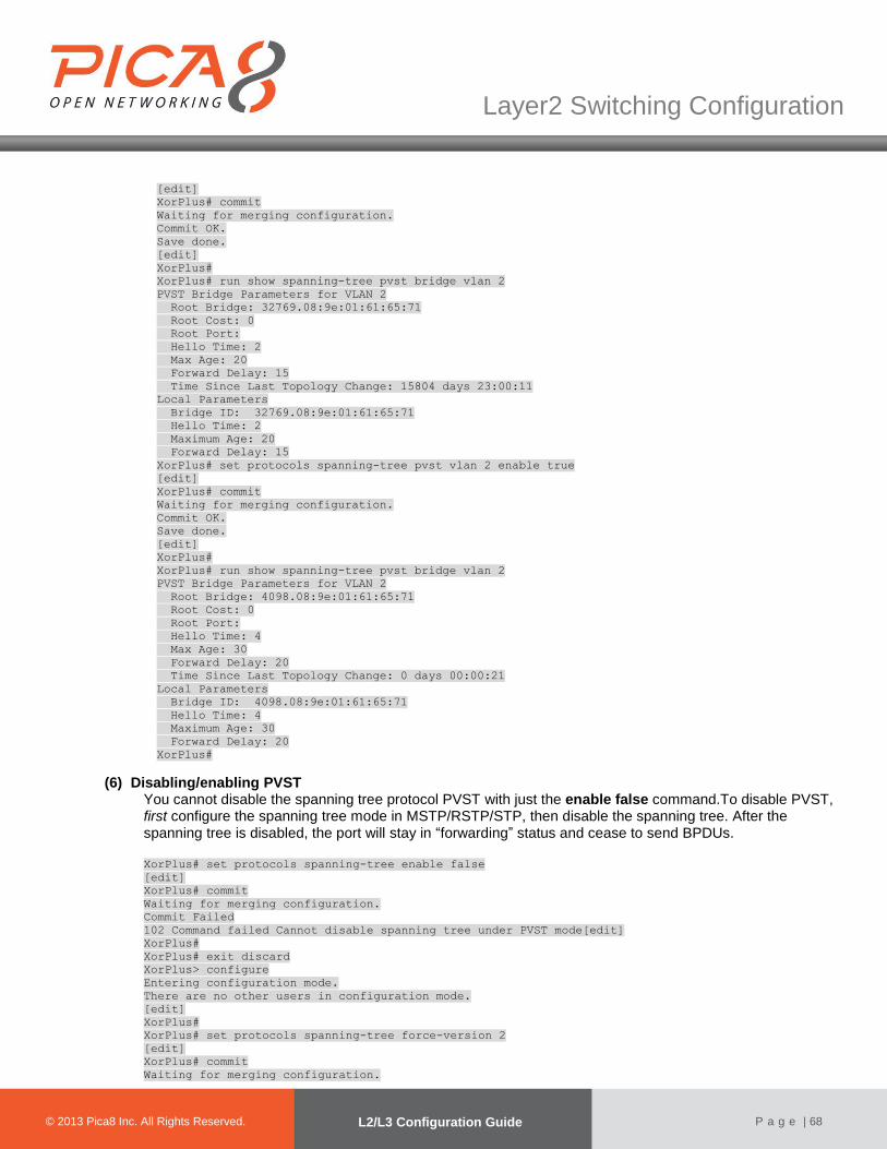
© 2012 Pica8 Inc. All © 2012 Pica8 Inc. All
Layer2 Switching Configuration
© 2013 Pica8 Inc. All Rights Reserved. L2/L3 Configuration Guide
P a g e | 68
[edit]
XorPlus# commit
Waiting for merging configuration.
Commit OK.
Save done.
[edit]
XorPlus#
XorPlus# run show spanning-tree pvst bridge vlan 2
PVST Bridge Parameters for VLAN 2
Root Bridge: 32769.08:9e:01:61:65:71
Root Cost: 0
Root Port:
Hello Time: 2
Max Age: 20
Forward Delay: 15
Time Since Last Topology Change: 15804 days 23:00:11
Local Parameters
Bridge ID: 32769.08:9e:01:61:65:71
Hello Time: 2
Maximum Age: 20
Forward Delay: 15
XorPlus# set protocols spanning-tree pvst vlan 2 enable true
[edit]
XorPlus# commit
Waiting for merging configuration.
Commit OK.
Save done.
[edit]
XorPlus#
XorPlus# run show spanning-tree pvst bridge vlan 2
PVST Bridge Parameters for VLAN 2
Root Bridge: 4098.08:9e:01:61:65:71
Root Cost: 0
Root Port:
Hello Time: 4
Max Age: 30
Forward Delay: 20
Time Since Last Topology Change: 0 days 00:00:21
Local Parameters
Bridge ID: 4098.08:9e:01:61:65:71
Hello Time: 4
Maximum Age: 30
Forward Delay: 20
XorPlus#
(6) Disabling/enabling PVST You cannot disable the spanning tree protocol PVST with just the enable false command.To disable PVST, first configure the spanning tree mode in MSTP/RSTP/STP, then disable the spanning tree. After the spanning tree is disabled, the port will stay in “forwarding” status and cease to send BPDUs. XorPlus# set protocols spanning-tree enable false
[edit]
XorPlus# commit
Waiting for merging configuration.
Commit Failed
102 Command failed Cannot disable spanning tree under PVST mode[edit]
XorPlus#
XorPlus# exit discard
XorPlus> configure
Entering configuration mode.
There are no other users in configuration mode.
[edit]
XorPlus#
XorPlus# set protocols spanning-tree force-version 2
[edit]
XorPlus# commit
Waiting for merging configuration.
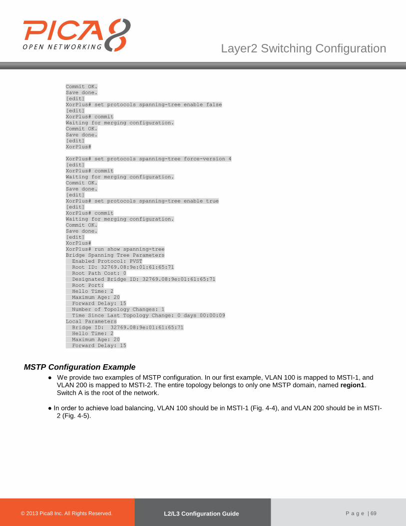
© 2012 Pica8 Inc. All © 2012 Pica8 Inc. All
Layer2 Switching Configuration
© 2013 Pica8 Inc. All Rights Reserved. L2/L3 Configuration Guide
P a g e | 69
Commit OK.
Save done.
[edit]
XorPlus# set protocols spanning-tree enable false
[edit]
XorPlus# commit
Waiting for merging configuration.
Commit OK.
Save done.
[edit]
XorPlus#
XorPlus# set protocols spanning-tree force-version 4
[edit]
XorPlus# commit
Waiting for merging configuration.
Commit OK.
Save done.
[edit]
XorPlus# set protocols spanning-tree enable true
[edit]
XorPlus# commit
Waiting for merging configuration.
Commit OK.
Save done.
[edit]
XorPlus#
XorPlus# run show spanning-tree
Bridge Spanning Tree Parameters
Enabled Protocol: PVST
Root ID: 32769.08:9e:01:61:65:71
Root Path Cost: 0
Designated Bridge ID: 32769.08:9e:01:61:65:71
Root Port:
Hello Time: 2
Maximum Age: 20
Forward Delay: 15
Number of Topology Changes: 1
Time Since Last Topology Change: 0 days 00:00:09
Local Parameters
Bridge ID: 32769.08:9e:01:61:65:71
Hello Time: 2
Maximum Age: 20
Forward Delay: 15
MSTP Configuration Example
● We provide two examples of MSTP configuration. In our first example, VLAN 100 is mapped to MSTI-1, and VLAN 200 is mapped to MSTI-2. The entire topology belongs to only one MSTP domain, named region1. Switch A is the root of the network.
● In order to achieve load balancing, VLAN 100 should be in MSTI-1 (Fig. 4-4), and VLAN 200 should be in MSTI-
2 (Fig. 4-5).
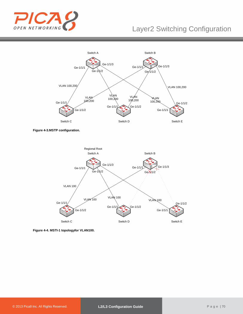
© 2012 Pica8 Inc. All © 2012 Pica8 Inc. All
Layer2 Switching Configuration
© 2013 Pica8 Inc. All Rights Reserved. L2/L3 Configuration Guide
P a g e | 70
Switch A
Switch C Switch ESwitch D
Ge-1/1/1
Ge-1/1/2
Ge-1/1/1
Ge-1/1/1
Ge-1/1/2
Ge-1/1/1
Ge-1/1/2
Ge-1/1/2
Switch B
Ge-1/1/3Ge-1/1/3
Ge-1/1/1
Ge-1/1/2
VLAN 100,200VLAN 100,200
VLAN
100,200
VLAN
100,200VLAN
100,200VLAN
100,200
Figure 4-3.MSTP configuration.
Switch A
Switch C Switch ESwitch D
Ge-1/1/1
Ge-1/1/2
Ge-1/1/1
Ge-1/1/1
Ge-1/1/2
Ge-1/1/1
Ge-1/1/2
Ge-1/1/2
Switch B
Ge-1/1/3Ge-1/1/3
Ge-1/1/1
Ge-1/1/2
VLAN 100
VLAN 100VLAN 100
VLAN 100
Regional Root
Figure 4-4. MSTI-1 topologyfor VLAN100.

© 2012 Pica8 Inc. All © 2012 Pica8 Inc. All
Layer2 Switching Configuration
© 2013 Pica8 Inc. All Rights Reserved. L2/L3 Configuration Guide
P a g e | 71
Switch A
Switch C Switch ESwitch D
Ge-1/1/1
Ge-1/1/2
Ge-1/1/1
Ge-1/1/1
Ge-1/1/2
Ge-1/1/1
Ge-1/1/2
Ge-1/1/2
Switch B
Ge-1/1/3Ge-1/1/3
Ge-1/1/1
Ge-1/1/2
VLAN 200 VLAN 200VLAN 200
VLAN 200
Regional Root
Figure 4-5. MSTI-2 topologyfor VLAN200.
(1) Configuring Switch A
ForSwitchA, configure ge-1/1/1~ge-1/1/3as trunk ports,and as members of VLAN 100 and VLAN 200. XorPlus# set vlans vlan-id 100
[edit]
XorPlus# set vlans vlan-id 200
[edit]
XorPlus# set interface gigabit-ethernet ge-1/1/1 family ethernet-switching port-mode trunk
[edit]
XorPlus# set interface gigabit-ethernet ge-1/1/1 family ethernet-switching vlan members 100
[edit]
XorPlus# set interface gigabit-ethernet ge-1/1/1 family ethernet-switching vlan members 200
[edit]
XorPlus# set interface gigabit-ethernet ge-1/1/2 family ethernet-switching port-mode trunk
[edit]
XorPlus# set interface gigabit-ethernet ge-1/1/2 family ethernet-switching vlan members 100
[edit]
XorPlus# set interface gigabit-ethernet ge-1/1/2 family ethernet-switching vlan members 200
[edit]
XorPlus# set interface gigabit-ethernet ge-1/1/3 family ethernet-switching port-mode trunk
[edit]
XorPlus# set interface gigabit-ethernet ge-1/1/3 family ethernet-switching vlan members 100
[edit]
XorPlus# set interface gigabit-ethernet ge-1/1/3 family ethernet-switching vlan members 200
[edit]
XorPlus# commit
Waiting for merging configuration.
Commit OK.
Save done.
[edit]
XorPlus#
XorPlus# set protocols spanning-tree mstp msti 1 vlan 100
[edit]
XorPlus# set protocols spanning-tree mstp msti 2 vlan 200
[edit]
XorPlus# set protocols spanning-tree mstp configuration-name region1
[edit]
XorPlus# commit
Waiting for merging configuration.
Commit OK.
Save done.
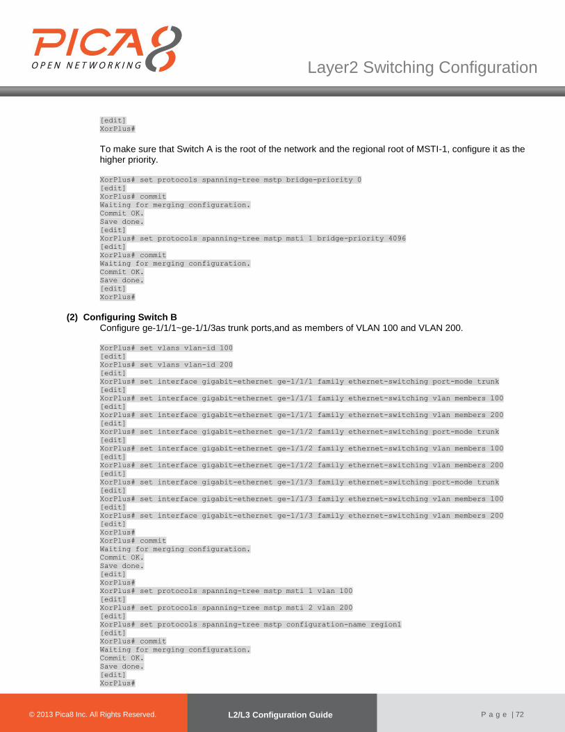
© 2012 Pica8 Inc. All © 2012 Pica8 Inc. All
Layer2 Switching Configuration
© 2013 Pica8 Inc. All Rights Reserved. L2/L3 Configuration Guide
P a g e | 72
[edit]
XorPlus#
To make sure that Switch A is the root of the network and the regional root of MSTI-1, configure it as the higher priority. XorPlus# set protocols spanning-tree mstp bridge-priority 0
[edit]
XorPlus# commit
Waiting for merging configuration.
Commit OK.
Save done.
[edit]
XorPlus# set protocols spanning-tree mstp msti 1 bridge-priority 4096
[edit]
XorPlus# commit
Waiting for merging configuration.
Commit OK.
Save done.
[edit]
XorPlus#
(2) Configuring Switch B Configure ge-1/1/1~ge-1/1/3as trunk ports,and as members of VLAN 100 and VLAN 200.
XorPlus# set vlans vlan-id 100
[edit]
XorPlus# set vlans vlan-id 200
[edit]
XorPlus# set interface gigabit-ethernet ge-1/1/1 family ethernet-switching port-mode trunk
[edit]
XorPlus# set interface gigabit-ethernet ge-1/1/1 family ethernet-switching vlan members 100
[edit]
XorPlus# set interface gigabit-ethernet ge-1/1/1 family ethernet-switching vlan members 200
[edit]
XorPlus# set interface gigabit-ethernet ge-1/1/2 family ethernet-switching port-mode trunk
[edit]
XorPlus# set interface gigabit-ethernet ge-1/1/2 family ethernet-switching vlan members 100
[edit]
XorPlus# set interface gigabit-ethernet ge-1/1/2 family ethernet-switching vlan members 200
[edit]
XorPlus# set interface gigabit-ethernet ge-1/1/3 family ethernet-switching port-mode trunk
[edit]
XorPlus# set interface gigabit-ethernet ge-1/1/3 family ethernet-switching vlan members 100
[edit]
XorPlus# set interface gigabit-ethernet ge-1/1/3 family ethernet-switching vlan members 200
[edit]
XorPlus#
XorPlus# commit
Waiting for merging configuration.
Commit OK.
Save done.
[edit]
XorPlus#
XorPlus# set protocols spanning-tree mstp msti 1 vlan 100
[edit]
XorPlus# set protocols spanning-tree mstp msti 2 vlan 200
[edit]
XorPlus# set protocols spanning-tree mstp configuration-name region1
[edit]
XorPlus# commit
Waiting for merging configuration.
Commit OK.
Save done.
[edit]
XorPlus#
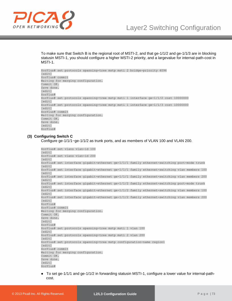
© 2012 Pica8 Inc. All © 2012 Pica8 Inc. All
Layer2 Switching Configuration
© 2013 Pica8 Inc. All Rights Reserved. L2/L3 Configuration Guide
P a g e | 73
To make sure that Switch B is the regional root of MSTI-2, and that ge-1/1/2 and ge-1/1/3 are in blocking statusin MSTI-1, you should configure a higher MSTI-2 priority, and a largevalue for internal-path-cost in MSTI-1. XorPlus# set protocols spanning-tree mstp msti 2 bridge-priority 4096
[edit]
XorPlus# commit
Waiting for merging configuration.
Commit OK.
Save done.
[edit]
XorPlus#
XorPlus# set protocols spanning-tree mstp msti 1 interface ge-1/1/2 cost 10000000
[edit]
XorPlus# set protocols spanning-tree mstp msti 1 interface ge-1/1/3 cost 10000000
[edit]
XorPlus# commit
Waiting for merging configuration.
Commit OK.
Save done.
[edit]
XorPlus#
(3) Configuring Switch C Configure ge-1/1/1~ge-1/1/2 as trunk ports, and as members of VLAN 100 and VLAN 200. XorPlus# set vlans vlan-id 100
[edit]
XorPlus# set vlans vlan-id 200
[edit]
XorPlus# set interface gigabit-ethernet ge-1/1/1 family ethernet-switching port-mode trunk
[edit]
XorPlus# set interface gigabit-ethernet ge-1/1/1 family ethernet-switching vlan members 100
[edit]
XorPlus# set interface gigabit-ethernet ge-1/1/1 family ethernet-switching vlan members 200
[edit]
XorPlus# set interface gigabit-ethernet ge-1/1/2 family ethernet-switching port-mode trunk
[edit]
XorPlus# set interface gigabit-ethernet ge-1/1/2 family ethernet-switching vlan members 100
[edit]
XorPlus# set interface gigabit-ethernet ge-1/1/2 family ethernet-switching vlan members 200
[edit]
XorPlus#
XorPlus# commit
Waiting for merging configuration.
Commit OK.
Save done.
[edit]
XorPlus#
XorPlus# set protocols spanning-tree mstp msti 1 vlan 100
[edit]
XorPlus# set protocols spanning-tree mstp msti 2 vlan 200
[edit]
XorPlus# set protocols spanning-tree mstp configuration-name region1
[edit]
XorPlus# commit
Waiting for merging configuration.
Commit OK.
Save done.
[edit]
XorPlus#
● To set ge-1/1/1 and ge-1/1/2 in forwarding statusin MSTI-1, configure a lower value for internal-path-cost.

© 2012 Pica8 Inc. All © 2012 Pica8 Inc. All
Layer2 Switching Configuration
© 2013 Pica8 Inc. All Rights Reserved. L2/L3 Configuration Guide
P a g e | 74
● To set ge-1/1/1 in blocking status in MSTI-2, configure a higher value for internal-path-cost. XorPlus# set protocols spanning-tree mstp msti 1 interface ge-1/1/1 cost 1000
[edit]
XorPlus# set protocols spanning-tree mstp msti 1 interface ge-1/1/2 cost 1000
[edit]
XorPlus# commit
Waiting for merging configuration.
Commit OK.
Save done.
[edit]
XorPlus# set protocols spanning-tree mstp msti 2 interface ge-1/1/1 cost 100000
[edit]
XorPlus# commit
Waiting for merging configuration.
Commit OK.
Save done.
[edit]
XorPlus#
(4) Configuring Switch D Configure ge-1/1/1~ge-1/1/2 as trunk ports,and as members of VLAN 100 and VLAN 200.
XorPlus# set vlans vlan-id 100
[edit]
XorPlus# set vlans vlan-id 200
[edit]
XorPlus# set interface gigabit-ethernet ge-1/1/1 family ethernet-switching port-mode trunk
[edit]
XorPlus# set interface gigabit-ethernet ge-1/1/1 family ethernet-switching vlan members 100
[edit]
XorPlus# set interface gigabit-ethernet ge-1/1/1 family ethernet-switching vlan members 200
[edit]
XorPlus# set interface gigabit-ethernet ge-1/1/2 family ethernet-switching port-mode trunk
[edit]
XorPlus# set interface gigabit-ethernet ge-1/1/2 family ethernet-switching vlan members 100
[edit]
XorPlus# set interface gigabit-ethernet ge-1/1/2 family ethernet-switching vlan members 200
[edit]
XorPlus#
XorPlus# commit
Waiting for merging configuration.
Commit OK.
Save done.
[edit]
XorPlus#
XorPlus# set protocols spanning-tree mstp msti 1 vlan 100
[edit]
XorPlus# set protocols spanning-tree mstp msti 2 vlan 200
[edit]
XorPlus# set protocols spanning-tree mstp configuration-name region1
[edit]
XorPlus# commit
Waiting for merging configuration.
Commit OK.
Save done.
[edit]
XorPlus#
To set ge-1/1/1 in blocking statusin MSTI-2 and ge-1/1/2 in blocking status in MSTI-1, configure a large value for internal-path-cost. XorPlus# set protocols spanning-tree mstp msti 2 interface ge-1/1/1 cost 10000000
[edit]

© 2012 Pica8 Inc. All © 2012 Pica8 Inc. All
Layer2 Switching Configuration
© 2013 Pica8 Inc. All Rights Reserved. L2/L3 Configuration Guide
P a g e | 75
XorPlus# commit
Waiting for merging configuration.
Commit OK.
Save done.
[edit]
XorPlus# set protocols spanning-tree mstp msti 1 interface ge-1/1/2 cost 10000000
[edit]
XorPlus# commit
Waiting for merging configuration.
Commit OK.
Save done.
[edit]
XorPlus#
(5) Configuring Switch E Configure ge-1/1/1~ge-1/1/2 as trunk ports,and as members of VLAN 100 and VLAN 200. XorPlus# set vlans vlan-id 100
[edit]
XorPlus# set vlans vlan-id 200
[edit]
XorPlus# set interface gigabit-ethernet ge-1/1/1 family ethernet-switching port-mode trunk
[edit]
XorPlus# set interface gigabit-ethernet ge-1/1/1 family ethernet-switching vlan members 100
[edit]
XorPlus# set interface gigabit-ethernet ge-1/1/1 family ethernet-switching vlan members 200
[edit]
XorPlus# set interface gigabit-ethernet ge-1/1/2 family ethernet-switching port-mode trunk
[edit]
XorPlus# set interface gigabit-ethernet ge-1/1/2 family ethernet-switching vlan members 100
[edit]
XorPlus# set interface gigabit-ethernet ge-1/1/2 family ethernet-switching vlan members 200
[edit]
XorPlus#
XorPlus# commit
Waiting for merging configuration.
Commit OK.
Save done.
[edit]
XorPlus#
XorPlus# set protocols spanning-tree mstp msti 1 vlan 100
[edit]
XorPlus# set protocols spanning-tree mstp msti 2 vlan 200
[edit]
XorPlus# set protocols spanning-tree mstp configuration-name region1
[edit]
XorPlus# commit
Waiting for merging configuration.
Commit OK.
Save done.
[edit]
XorPlus#
● To set ge-1/1/1 and ge-1/1/2 in forwarding status in MSTI-2, configure a lower value for internal-path-cost.
● To set ge-1/1/2 in blocking status in MSTI-1, configure a large value for internal-path-cost.
XorPlus# set protocols spanning-tree mstp msti 2 interface ge-1/1/1 cost 1000
[edit]
XorPlus# set protocols spanning-tree mstp msti 2 interface ge-1/1/2 cost 1000
[edit]
XorPlus# commit
Waiting for merging configuration.
Commit OK.
Save done.

© 2012 Pica8 Inc. All © 2012 Pica8 Inc. All
Layer2 Switching Configuration
© 2013 Pica8 Inc. All Rights Reserved. L2/L3 Configuration Guide
P a g e | 76
[edit]
XorPlus# set protocols spanning-tree mstp msti 1 interface ge-1/1/2 cost 10000000
[edit]
XorPlus# commit
Waiting for merging configuration.
Commit OK.
Save done.
[edit]
XorPlus#
● Inour second example, there are two regions. In region 1, VLAN 100 is mapped to MSTI-1, VLAN 200 is mapped to MSTI-2, and VLAN 300 is mapped to MSTI-3. In region 2, VLAN 200 is mapped to MSTI-2, and VLAN 400 is mapped to MSTI-4. Switch A is the root of the entire network.
● The topologies of the VLANs are presented in Fig. 4-6 through 4-10.
Switch A
Switch C
Switch ESwitch D
Ge-1/1/1
Ge-1/1/2
Ge-1/1/1 Ge-1/1/1
Ge-1/1/2
Ge-1/1/2
Switch B
Ge-1/1/3Ge-1/1/3
Ge-1/1/1 Ge-1/1/2
ROOT
Ge-1/1/1
Ge-1/1/2
Region 1
Region 2Ge-1/1/3 Ge-1/1/3
Figure 4-6. MSTP configuration.

© 2012 Pica8 Inc. All © 2012 Pica8 Inc. All
Layer2 Switching Configuration
© 2013 Pica8 Inc. All Rights Reserved. L2/L3 Configuration Guide
P a g e | 77
Switch A
Switch C
Switch ESwitch D
Ge-1/1/1
Ge-1/1/2
Ge-1/1/1 Ge-1/1/1
Ge-1/1/2
Ge-1/1/2
Switch B
Ge-1/1/3Ge-1/1/3
Ge-1/1/1 Ge-1/1/2
Regional Root
Ge-1/1/1
Ge-1/1/2
Region 1
Region 2Ge-1/1/3 Ge-1/1/3
VLAN 100VLAN 100
VLAN 100
VLAN 100
Regional Root
Figure 4-7.Topologyfor VLAN 100.
Switch A
Switch C
Switch ESwitch D
Ge-1/1/1
Ge-1/1/2
Ge-1/1/1 Ge-1/1/1
Ge-1/1/2
Ge-1/1/2
Switch B
Ge-1/1/3Ge-1/1/3
Ge-1/1/1 Ge-1/1/2
Regional Root
Ge-1/1/1
Ge-1/1/2
Region 1
Region 2Ge-1/1/3 Ge-1/1/3
VLAN 200
VLAN 200
VLAN 200
VLAN 200
Regional Root
Figure 4-8.Topologyfor VLAN 200.

© 2012 Pica8 Inc. All © 2012 Pica8 Inc. All
Layer2 Switching Configuration
© 2013 Pica8 Inc. All Rights Reserved. L2/L3 Configuration Guide
P a g e | 78
Switch A
Switch C
Switch ESwitch D
Ge-1/1/1
Ge-1/1/2
Ge-1/1/1 Ge-1/1/1
Ge-1/1/2
Ge-1/1/2
Switch B
Ge-1/1/3Ge-1/1/3
Ge-1/1/1 Ge-1/1/2
Regional
Root
Ge-1/1/1
Ge-1/1/2
Region 1
Region 2Ge-1/1/3 Ge-1/1/3
VLAN 300
VLAN 300
VLAN 300
VLAN 300
Regional Root
Figure 4-9.Topologyfor VLAN 300.
Switch A
Switch C
Switch ESwitch D
Ge-1/1/1
Ge-1/1/2
Ge-1/1/1 Ge-1/1/1
Ge-1/1/2
Ge-1/1/2
Switch B
Ge-1/1/3Ge-1/1/3
Ge-1/1/1 Ge-1/1/2
Regional Root
Ge-1/1/1
Ge-1/1/2
Region 1
Region 2Ge-1/1/3 Ge-1/1/3
VLAN 400 VLAN 400
VLAN 400
VLAN 400
Regional Root
Figure 4-10.Topologyfor VLAN 400.
(1) Configuring Switch A For SwitchA, configure ge-1/1/1~ge-1/1/2 as trunk ports,and as members of VLAN 100, VLAN 200, VLAN 300, and VLAN 400. XorPlus# set vlans vlan-id 100
[edit]
XorPlus# set vlans vlan-id 200
[edit]
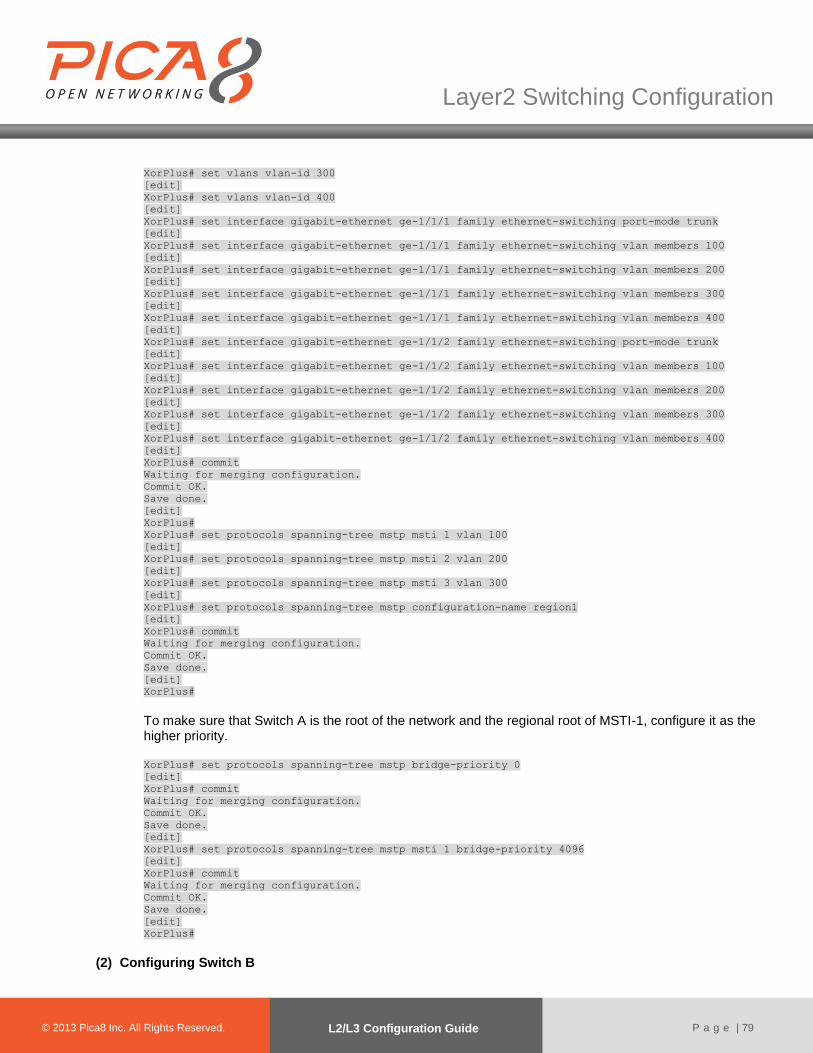
© 2012 Pica8 Inc. All © 2012 Pica8 Inc. All
Layer2 Switching Configuration
© 2013 Pica8 Inc. All Rights Reserved. L2/L3 Configuration Guide
P a g e | 79
XorPlus# set vlans vlan-id 300
[edit]
XorPlus# set vlans vlan-id 400
[edit]
XorPlus# set interface gigabit-ethernet ge-1/1/1 family ethernet-switching port-mode trunk
[edit]
XorPlus# set interface gigabit-ethernet ge-1/1/1 family ethernet-switching vlan members 100
[edit]
XorPlus# set interface gigabit-ethernet ge-1/1/1 family ethernet-switching vlan members 200
[edit]
XorPlus# set interface gigabit-ethernet ge-1/1/1 family ethernet-switching vlan members 300
[edit]
XorPlus# set interface gigabit-ethernet ge-1/1/1 family ethernet-switching vlan members 400
[edit]
XorPlus# set interface gigabit-ethernet ge-1/1/2 family ethernet-switching port-mode trunk
[edit]
XorPlus# set interface gigabit-ethernet ge-1/1/2 family ethernet-switching vlan members 100
[edit]
XorPlus# set interface gigabit-ethernet ge-1/1/2 family ethernet-switching vlan members 200
[edit]
XorPlus# set interface gigabit-ethernet ge-1/1/2 family ethernet-switching vlan members 300
[edit]
XorPlus# set interface gigabit-ethernet ge-1/1/2 family ethernet-switching vlan members 400
[edit]
XorPlus# commit
Waiting for merging configuration.
Commit OK.
Save done.
[edit]
XorPlus#
XorPlus# set protocols spanning-tree mstp msti 1 vlan 100
[edit]
XorPlus# set protocols spanning-tree mstp msti 2 vlan 200
[edit]
XorPlus# set protocols spanning-tree mstp msti 3 vlan 300
[edit]
XorPlus# set protocols spanning-tree mstp configuration-name region1
[edit]
XorPlus# commit
Waiting for merging configuration.
Commit OK.
Save done.
[edit]
XorPlus#
To make sure that Switch A is the root of the network and the regional root of MSTI-1, configure it as the higher priority.
XorPlus# set protocols spanning-tree mstp bridge-priority 0
[edit]
XorPlus# commit
Waiting for merging configuration.
Commit OK.
Save done.
[edit]
XorPlus# set protocols spanning-tree mstp msti 1 bridge-priority 4096
[edit]
XorPlus# commit
Waiting for merging configuration.
Commit OK.
Save done.
[edit]
XorPlus#
(2) Configuring Switch B
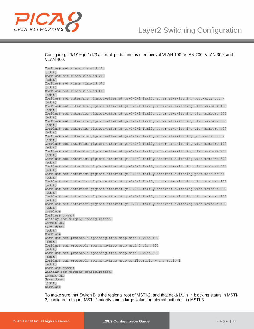
© 2012 Pica8 Inc. All © 2012 Pica8 Inc. All
Layer2 Switching Configuration
© 2013 Pica8 Inc. All Rights Reserved. L2/L3 Configuration Guide
P a g e | 80
Configure ge-1/1/1~ge-1/1/3 as trunk ports, and as members of VLAN 100, VLAN 200, VLAN 300, and VLAN 400.
XorPlus# set vlans vlan-id 100
[edit]
XorPlus# set vlans vlan-id 200
[edit]
XorPlus# set vlans vlan-id 300
[edit]
XorPlus# set vlans vlan-id 400
[edit]
XorPlus# set interface gigabit-ethernet ge-1/1/1 family ethernet-switching port-mode trunk
[edit]
XorPlus# set interface gigabit-ethernet ge-1/1/1 family ethernet-switching vlan members 100
[edit]
XorPlus# set interface gigabit-ethernet ge-1/1/1 family ethernet-switching vlan members 200
[edit]
XorPlus# set interface gigabit-ethernet ge-1/1/1 family ethernet-switching vlan members 300
[edit]
XorPlus# set interface gigabit-ethernet ge-1/1/1 family ethernet-switching vlan members 400
[edit]
XorPlus# set interface gigabit-ethernet ge-1/1/2 family ethernet-switching port-mode trunk
[edit]
XorPlus# set interface gigabit-ethernet ge-1/1/2 family ethernet-switching vlan members 100
[edit]
XorPlus# set interface gigabit-ethernet ge-1/1/2 family ethernet-switching vlan members 200
[edit]
XorPlus# set interface gigabit-ethernet ge-1/1/2 family ethernet-switching vlan members 300
[edit]
XorPlus# set interface gigabit-ethernet ge-1/1/2 family ethernet-switching vlan members 400
[edit]
XorPlus# set interface gigabit-ethernet ge-1/1/3 family ethernet-switching port-mode trunk
[edit]
XorPlus# set interface gigabit-ethernet ge-1/1/3 family ethernet-switching vlan members 100
[edit]
XorPlus# set interface gigabit-ethernet ge-1/1/3 family ethernet-switching vlan members 200
[edit]
XorPlus# set interface gigabit-ethernet ge-1/1/3 family ethernet-switching vlan members 300
[edit]
XorPlus# set interface gigabit-ethernet ge-1/1/3 family ethernet-switching vlan members 400
[edit]
XorPlus#
XorPlus# commit
Waiting for merging configuration.
Commit OK.
Save done.
[edit]
XorPlus#
XorPlus# set protocols spanning-tree mstp msti 1 vlan 100
[edit]
XorPlus# set protocols spanning-tree mstp msti 2 vlan 200
[edit]
XorPlus# set protocols spanning-tree mstp msti 3 vlan 300
[edit]
XorPlus# set protocols spanning-tree mstp configuration-name region1
[edit]
XorPlus# commit
Waiting for merging configuration.
Commit OK.
Save done.
[edit]
XorPlus#
To make sure that Switch B is the regional root of MSTI-2, and that ge-1/1/1 is in blocking status in MSTI-3, configure a higher MSTI-2 priority, and a large value for internal-path-cost in MSTI-3.
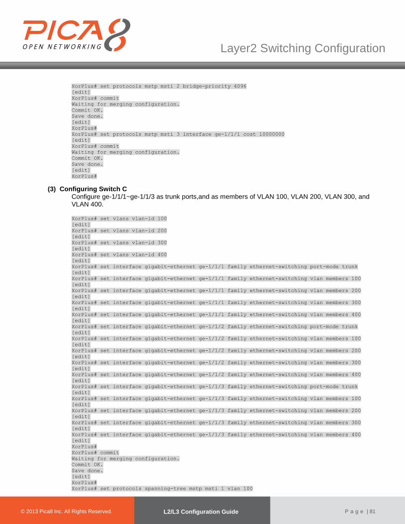
© 2012 Pica8 Inc. All © 2012 Pica8 Inc. All
Layer2 Switching Configuration
© 2013 Pica8 Inc. All Rights Reserved. L2/L3 Configuration Guide
P a g e | 81
XorPlus# set protocols mstp msti 2 bridge-priority 4096
[edit]
XorPlus# commit
Waiting for merging configuration.
Commit OK.
Save done.
[edit]
XorPlus#
XorPlus# set protocols mstp msti 3 interface ge-1/1/1 cost 10000000
[edit]
XorPlus# commit
Waiting for merging configuration.
Commit OK.
Save done.
[edit]
XorPlus#
(3) Configuring Switch C Configure ge-1/1/1~ge-1/1/3 as trunk ports,and as members of VLAN 100, VLAN 200, VLAN 300, and VLAN 400.
XorPlus# set vlans vlan-id 100
[edit]
XorPlus# set vlans vlan-id 200
[edit]
XorPlus# set vlans vlan-id 300
[edit]
XorPlus# set vlans vlan-id 400
[edit]
XorPlus# set interface gigabit-ethernet ge-1/1/1 family ethernet-switching port-mode trunk
[edit]
XorPlus# set interface gigabit-ethernet ge-1/1/1 family ethernet-switching vlan members 100
[edit]
XorPlus# set interface gigabit-ethernet ge-1/1/1 family ethernet-switching vlan members 200
[edit]
XorPlus# set interface gigabit-ethernet ge-1/1/1 family ethernet-switching vlan members 300
[edit]
XorPlus# set interface gigabit-ethernet ge-1/1/1 family ethernet-switching vlan members 400
[edit]
XorPlus# set interface gigabit-ethernet ge-1/1/2 family ethernet-switching port-mode trunk
[edit]
XorPlus# set interface gigabit-ethernet ge-1/1/2 family ethernet-switching vlan members 100
[edit]
XorPlus# set interface gigabit-ethernet ge-1/1/2 family ethernet-switching vlan members 200
[edit]
XorPlus# set interface gigabit-ethernet ge-1/1/2 family ethernet-switching vlan members 300
[edit]
XorPlus# set interface gigabit-ethernet ge-1/1/2 family ethernet-switching vlan members 400
[edit]
XorPlus# set interface gigabit-ethernet ge-1/1/3 family ethernet-switching port-mode trunk
[edit]
XorPlus# set interface gigabit-ethernet ge-1/1/3 family ethernet-switching vlan members 100
[edit]
XorPlus# set interface gigabit-ethernet ge-1/1/3 family ethernet-switching vlan members 200
[edit]
XorPlus# set interface gigabit-ethernet ge-1/1/3 family ethernet-switching vlan members 300
[edit]
XorPlus# set interface gigabit-ethernet ge-1/1/3 family ethernet-switching vlan members 400
[edit]
XorPlus#
XorPlus# commit
Waiting for merging configuration.
Commit OK.
Save done.
[edit]
XorPlus#
XorPlus# set protocols spanning-tree mstp msti 1 vlan 100
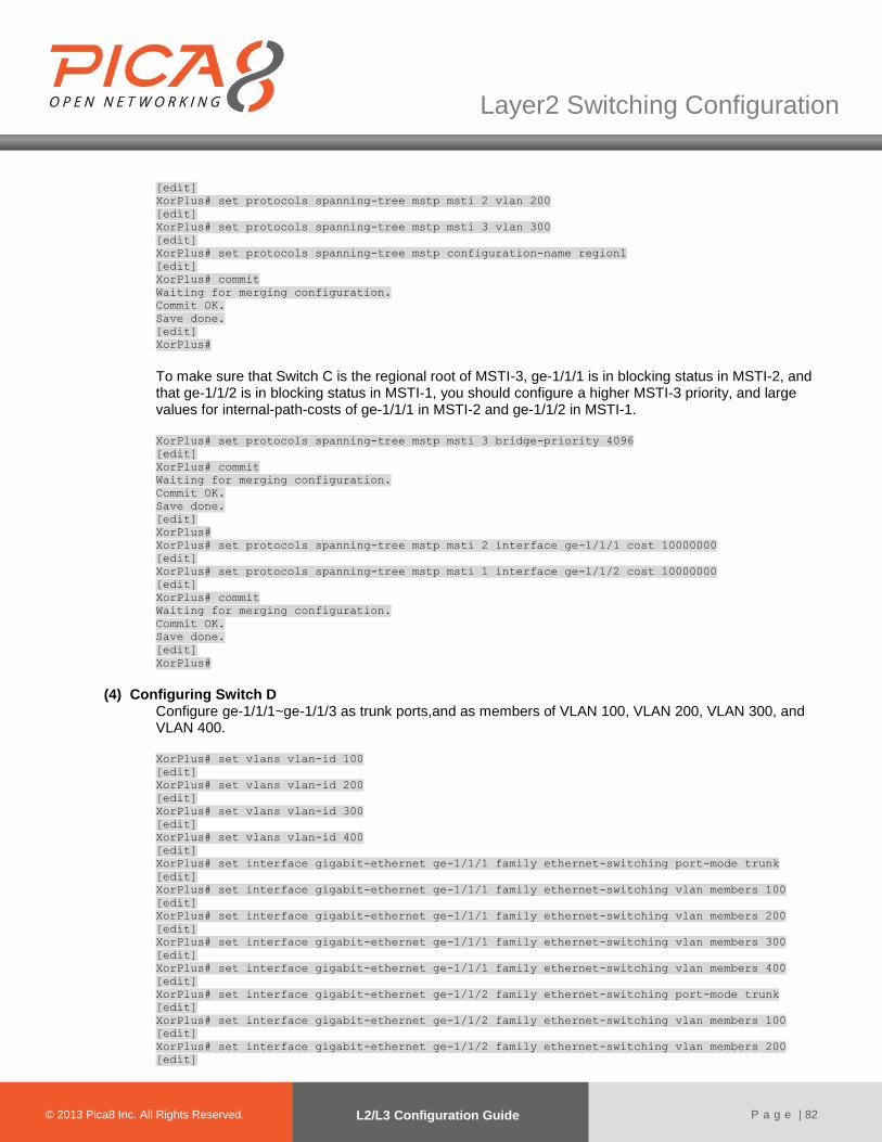
© 2012 Pica8 Inc. All © 2012 Pica8 Inc. All
Layer2 Switching Configuration
© 2013 Pica8 Inc. All Rights Reserved. L2/L3 Configuration Guide
P a g e | 82
[edit]
XorPlus# set protocols spanning-tree mstp msti 2 vlan 200
[edit]
XorPlus# set protocols spanning-tree mstp msti 3 vlan 300
[edit]
XorPlus# set protocols spanning-tree mstp configuration-name region1
[edit]
XorPlus# commit
Waiting for merging configuration.
Commit OK.
Save done.
[edit]
XorPlus#
To make sure that Switch C is the regional root of MSTI-3, ge-1/1/1 is in blocking status in MSTI-2, and that ge-1/1/2 is in blocking status in MSTI-1, you should configure a higher MSTI-3 priority, and large values for internal-path-costs of ge-1/1/1 in MSTI-2 and ge-1/1/2 in MSTI-1.
XorPlus# set protocols spanning-tree mstp msti 3 bridge-priority 4096
[edit]
XorPlus# commit
Waiting for merging configuration.
Commit OK.
Save done.
[edit]
XorPlus#
XorPlus# set protocols spanning-tree mstp msti 2 interface ge-1/1/1 cost 10000000
[edit]
XorPlus# set protocols spanning-tree mstp msti 1 interface ge-1/1/2 cost 10000000
[edit]
XorPlus# commit
Waiting for merging configuration.
Commit OK.
Save done.
[edit]
XorPlus#
(4) Configuring Switch D Configure ge-1/1/1~ge-1/1/3 as trunk ports,and as members of VLAN 100, VLAN 200, VLAN 300, and VLAN 400.
XorPlus# set vlans vlan-id 100
[edit]
XorPlus# set vlans vlan-id 200
[edit]
XorPlus# set vlans vlan-id 300
[edit]
XorPlus# set vlans vlan-id 400
[edit]
XorPlus# set interface gigabit-ethernet ge-1/1/1 family ethernet-switching port-mode trunk
[edit]
XorPlus# set interface gigabit-ethernet ge-1/1/1 family ethernet-switching vlan members 100
[edit]
XorPlus# set interface gigabit-ethernet ge-1/1/1 family ethernet-switching vlan members 200
[edit]
XorPlus# set interface gigabit-ethernet ge-1/1/1 family ethernet-switching vlan members 300
[edit]
XorPlus# set interface gigabit-ethernet ge-1/1/1 family ethernet-switching vlan members 400
[edit]
XorPlus# set interface gigabit-ethernet ge-1/1/2 family ethernet-switching port-mode trunk
[edit]
XorPlus# set interface gigabit-ethernet ge-1/1/2 family ethernet-switching vlan members 100
[edit]
XorPlus# set interface gigabit-ethernet ge-1/1/2 family ethernet-switching vlan members 200
[edit]
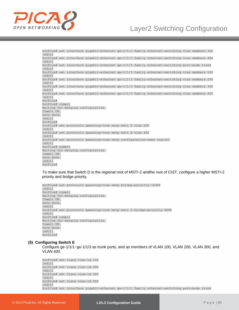
© 2012 Pica8 Inc. All © 2012 Pica8 Inc. All
Layer2 Switching Configuration
© 2013 Pica8 Inc. All Rights Reserved. L2/L3 Configuration Guide
P a g e | 83
XorPlus# set interface gigabit-ethernet ge-1/1/2 family ethernet-switching vlan members 300
[edit]
XorPlus# set interface gigabit-ethernet ge-1/1/2 family ethernet-switching vlan members 400
[edit]
XorPlus# set interface gigabit-ethernet ge-1/1/3 family ethernet-switching port-mode trunk
[edit]
XorPlus# set interface gigabit-ethernet ge-1/1/3 family ethernet-switching vlan members 100
[edit]
XorPlus# set interface gigabit-ethernet ge-1/1/3 family ethernet-switching vlan members 200
[edit]
XorPlus# set interface gigabit-ethernet ge-1/1/3 family ethernet-switching vlan members 300
[edit]
XorPlus# set interface gigabit-ethernet ge-1/1/3 family ethernet-switching vlan members 400
[edit]
XorPlus#
XorPlus# commit
Waiting for merging configuration.
Commit OK.
Save done.
[edit]
XorPlus#
XorPlus# set protocols spanning-tree mstp msti 2 vlan 200
[edit]
XorPlus# set protocols spanning-tree mstp msti 4 vlan 400
[edit]
XorPlus# set protocols spanning-tree mstp configuration-name region2
[edit]
XorPlus# commit
Waiting for merging configuration.
Commit OK.
Save done.
[edit]
XorPlus#
To make sure that Switch D is the regional root of MSTI-2 andthe root of CIST, configure a higher MSTI-2 priority and bridge priority.
XorPlus# set protocols spanning-tree mstp bridge-priority 16384
[edit]
XorPlus# commit
Waiting for merging configuration.
Commit OK.
Save done.
[edit]
XorPlus# set protocols spanning-tree mstp msti 2 bridge-priority 4096
[edit]
XorPlus# commit
Waiting for merging configuration.
Commit OK.
Save done.
[edit]
XorPlus#
(5) Configuring Switch E Configure ge-1/1/1~ge-1/1/3 as trunk ports, and as members of VLAN 100, VLAN 200, VLAN 300, and VLAN 400.
XorPlus# set vlans vlan-id 100
[edit]
XorPlus# set vlans vlan-id 200
[edit]
XorPlus# set vlans vlan-id 300
[edit]
XorPlus# set vlans vlan-id 400
[edit]
XorPlus# set interface gigabit-ethernet ge-1/1/1 family ethernet-switching port-mode trunk

© 2012 Pica8 Inc. All © 2012 Pica8 Inc. All
Layer2 Switching Configuration
© 2013 Pica8 Inc. All Rights Reserved. L2/L3 Configuration Guide
P a g e | 84
[edit]
XorPlus# set interface gigabit-ethernet ge-1/1/1 family ethernet-switching vlan members 100
[edit]
XorPlus# set interface gigabit-ethernet ge-1/1/1 family ethernet-switching vlan members 200
[edit]
XorPlus# set interface gigabit-ethernet ge-1/1/1 family ethernet-switching vlan members 300
[edit]
XorPlus# set interface gigabit-ethernet ge-1/1/1 family ethernet-switching vlan members 400
[edit]
XorPlus# set interface gigabit-ethernet ge-1/1/2 family ethernet-switching port-mode trunk
[edit]
XorPlus# set interface gigabit-ethernet ge-1/1/2 family ethernet-switching vlan members 100
[edit]
XorPlus# set interface gigabit-ethernet ge-1/1/2 family ethernet-switching vlan members 200
[edit]
XorPlus# set interface gigabit-ethernet ge-1/1/2 family ethernet-switching vlan members 300
[edit]
XorPlus# set interface gigabit-ethernet ge-1/1/2 family ethernet-switching vlan members 400
[edit]
XorPlus# set interface gigabit-ethernet ge-1/1/3 family ethernet-switching port-mode trunk
[edit]
XorPlus# set interface gigabit-ethernet ge-1/1/3 family ethernet-switching vlan members 100
[edit]
XorPlus# set interface gigabit-ethernet ge-1/1/3 family ethernet-switching vlan members 200
[edit]
XorPlus# set interface gigabit-ethernet ge-1/1/3 family ethernet-switching vlan members 300
[edit]
XorPlus# set interface gigabit-ethernet ge-1/1/3 family ethernet-switching vlan members 400
[edit]
XorPlus#
XorPlus# commit
Waiting for merging configuration.
Commit OK.
Save done.
[edit]
XorPlus#
XorPlus# set protocols spanning-tree mstp msti 2 vlan 200
[edit]
XorPlus# set protocols spanning-tree mstp msti 4 vlan 400
[edit]
XorPlus# set protocols spanning-tree mstp configuration-name region2
[edit]
XorPlus# commit
Waiting for merging configuration.
Commit OK.
Save done.
[edit]
XorPlus#
To make sure that Switch E is the regional root of MSTI-4, configure a higher MSTI-4 priority. XorPlus# set protocols spanning-tree mstp msti 4 bridge-priority 4096
[edit]
XorPlus# commit
Waiting for merging configuration.
Commit OK.
Save done.
[edit]
XorPlus#
PVST Configuration Example
In the following topology, we provide anexample of PVST configuration.Switches A and B are in the aggregation layer, and switches C and D are in the access layer. Configure switch A as the root bridge of VLAN 100 and VLAN 200, switch B as the root bridge of VLAN 300, and switch C as the root bridge of VLAN 400.

© 2012 Pica8 Inc. All © 2012 Pica8 Inc. All
Layer2 Switching Configuration
© 2013 Pica8 Inc. All Rights Reserved. L2/L3 Configuration Guide
P a g e | 85
Switch A
Switch C Switch D
Ge-1/1/1
Ge-1/1/2
Ge-1/1/1 Ge-1/1/1
Ge-1/1/2
Ge-1/1/2
Switch B
Ge-1/1/3Ge-1/1/3
Ge-1/1/1
Ge-1/1/2Ge-1/1/3 Ge-1/1/3
Permit: all VLAN
Permit: VLAN
100, 200
Permit: VLAN 200, 400
Permit: VLAN
100, 200Permit: VLAN
200, 300
Permit: VLAN
200, 300
Figure 4-11. PVST configuration.
(1) Configuring Switch A
For Switch A, configure ge-1/1/1~ge-1/1/3 as trunk ports,and ge-1/1/1 as a member of VLANs 100, 200, 300, and 400; ge-1/1/2 as a member of VLANs 200 and 300; and ge-1/1/3 as a member of VLANs 100 and 200.
XorPlus# set vlans vlan-id 100
[edit]
XorPlus# set vlans vlan-id 200
[edit]
XorPlus# set vlans vlan-id 300
[edit]
XorPlus# set vlans vlan-id 400
[edit]
XorPlus# set interface gigabit-ethernet ge-1/1/1 family ethernet-switching port-mode trunk
[edit]
XorPlus# set interface gigabit-ethernet ge-1/1/1 family ethernet-switching vlan members 100
[edit]
XorPlus# set interface gigabit-ethernet ge-1/1/1 family ethernet-switching vlan members 200
[edit]
XorPlus# set interface gigabit-ethernet ge-1/1/1 family ethernet-switching vlan members 300
[edit]
XorPlus# set interface gigabit-ethernet ge-1/1/1 family ethernet-switching vlan members 400
[edit]
XorPlus# set interface gigabit-ethernet ge-1/1/2 family ethernet-switching port-mode trunk
[edit]
XorPlus# set interface gigabit-ethernet ge-1/1/2 family ethernet-switching vlan members 200
[edit]
XorPlus# set interface gigabit-ethernet ge-1/1/2 family ethernet-switching vlan members 300
[edit]
XorPlus# set interface gigabit-ethernet ge-1/1/3 family ethernet-switching port-mode trunk
[edit]
XorPlus# set interface gigabit-ethernet ge-1/1/3 family ethernet-switching vlan members 100
[edit]
XorPlus# set interface gigabit-ethernet ge-1/1/3 family ethernet-switching vlan members 200
[edit]
XorPlus# commit
Waiting for merging configuration.
Commit OK.
Save done.
[edit]
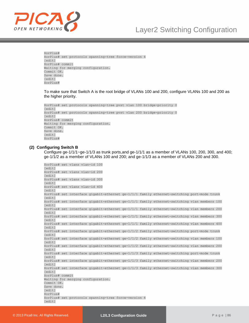
© 2012 Pica8 Inc. All © 2012 Pica8 Inc. All
Layer2 Switching Configuration
© 2013 Pica8 Inc. All Rights Reserved. L2/L3 Configuration Guide
P a g e | 86
XorPlus#
XorPlus# set protocols spanning-tree force-version 4
[edit]
XorPlus# commit
Waiting for merging configuration.
Commit OK.
Save done.
[edit]
XorPlus#
To make sure that Switch A is the root bridge of VLANs 100 and 200, configure VLANs 100 and 200 as the higher priority.
XorPlus# set protocols spanning-tree pvst vlan 100 bridge-priority 0
[edit]
XorPlus# set protocols spanning-tree pvst vlan 200 bridge-priority 0
[edit]
XorPlus# commit
Waiting for merging configuration.
Commit OK.
Save done.
[edit]
XorPlus#
(2) Configuring Switch B Configure ge-1/1/1~ge-1/1/3 as trunk ports,and ge-1/1/1 as a member of VLANs 100, 200, 300, and 400; ge-1/1/2 as a member of VLANs 100 and 200; and ge-1/1/3 as a member of VLANs 200 and 300.
XorPlus# set vlans vlan-id 100
[edit]
XorPlus# set vlans vlan-id 200
[edit]
XorPlus# set vlans vlan-id 300
[edit]
XorPlus# set vlans vlan-id 400
[edit]
XorPlus# set interface gigabit-ethernet ge-1/1/1 family ethernet-switching port-mode trunk
[edit]
XorPlus# set interface gigabit-ethernet ge-1/1/1 family ethernet-switching vlan members 100
[edit]
XorPlus# set interface gigabit-ethernet ge-1/1/1 family ethernet-switching vlan members 200
[edit]
XorPlus# set interface gigabit-ethernet ge-1/1/1 family ethernet-switching vlan members 300
[edit]
XorPlus# set interface gigabit-ethernet ge-1/1/1 family ethernet-switching vlan members 400
[edit]
XorPlus# set interface gigabit-ethernet ge-1/1/2 family ethernet-switching port-mode trunk
[edit]
XorPlus# set interface gigabit-ethernet ge-1/1/2 family ethernet-switching vlan members 100
[edit]
XorPlus# set interface gigabit-ethernet ge-1/1/2 family ethernet-switching vlan members 200
[edit]
XorPlus# set interface gigabit-ethernet ge-1/1/3 family ethernet-switching port-mode trunk
[edit]
XorPlus# set interface gigabit-ethernet ge-1/1/3 family ethernet-switching vlan members 200
[edit]
XorPlus# set interface gigabit-ethernet ge-1/1/3 family ethernet-switching vlan members 300
[edit]
XorPlus# commit
Waiting for merging configuration.
Commit OK.
Save done.
[edit]
XorPlus#
XorPlus# set protocols spanning-tree force-version 4
[edit]
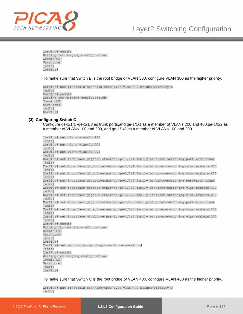
© 2012 Pica8 Inc. All © 2012 Pica8 Inc. All
Layer2 Switching Configuration
© 2013 Pica8 Inc. All Rights Reserved. L2/L3 Configuration Guide
P a g e | 87
XorPlus# commit
Waiting for merging configuration.
Commit OK.
Save done.
[edit]
XorPlus#
To make sure that Switch B is the root bridge of VLAN 300, configure VLAN 300 as the higher priority.
XorPlus# set protocols spanning-tree pvst vlan 300 bridge-priority 0
[edit]
XorPlus# commit
Waiting for merging configuration.
Commit OK.
Save done.
[edit]
XorPlus#
(3) Configuring Switch C Configure ge-1/1/1~ge-1/1/3 as trunk ports,and ge-1/1/1 as a member of VLANs 200 and 400,ge-1/1/2 as a member of VLANs 100 and 200, and ge-1/1/3 as a member of VLANs 100 and 200.
XorPlus# set vlans vlan-id 100
[edit]
XorPlus# set vlans vlan-id 200
[edit]
XorPlus# set vlans vlan-id 400
[edit]
XorPlus# set interface gigabit-ethernet ge-1/1/1 family ethernet-switching port-mode trunk
[edit]
XorPlus# set interface gigabit-ethernet ge-1/1/1 family ethernet-switching vlan members 200
[edit]
XorPlus# set interface gigabit-ethernet ge-1/1/1 family ethernet-switching vlan members 400
[edit]
XorPlus# set interface gigabit-ethernet ge-1/1/2 family ethernet-switching port-mode trunk
[edit]
XorPlus# set interface gigabit-ethernet ge-1/1/2 family ethernet-switching vlan members 100
[edit]
XorPlus# set interface gigabit-ethernet ge-1/1/2 family ethernet-switching vlan members 200
[edit]
XorPlus# set interface gigabit-ethernet ge-1/1/3 family ethernet-switching port-mode trunk
[edit]
XorPlus# set interface gigabit-ethernet ge-1/1/3 family ethernet-switching vlan members 100
[edit]
XorPlus# set interface gigabit-ethernet ge-1/1/3 family ethernet-switching vlan members 200
[edit]
XorPlus# commit
Waiting for merging configuration.
Commit OK.
Save done.
[edit]
XorPlus#
XorPlus# set protocols spanning-tree force-version 4
[edit]
XorPlus# commit
Waiting for merging configuration.
Commit OK.
Save done.
[edit]
XorPlus#
To make sure that Switch C is the root bridge of VLAN 400, configure VLAN 400 as the higher priority.
XorPlus# set protocols spanning-tree pvst vlan 400 bridge-priority 0
[edit]
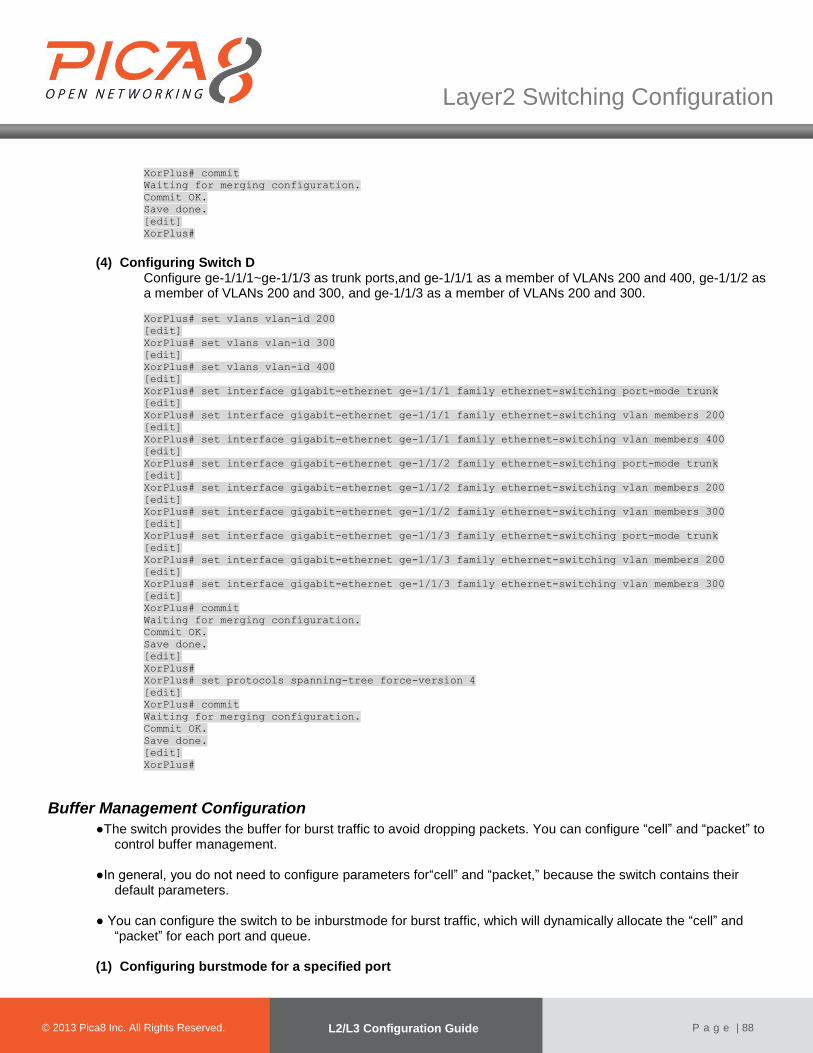
© 2012 Pica8 Inc. All © 2012 Pica8 Inc. All
Layer2 Switching Configuration
© 2013 Pica8 Inc. All Rights Reserved. L2/L3 Configuration Guide
P a g e | 88
XorPlus# commit
Waiting for merging configuration.
Commit OK.
Save done.
[edit]
XorPlus#
(4) Configuring Switch D Configure ge-1/1/1~ge-1/1/3 as trunk ports,and ge-1/1/1 as a member of VLANs 200 and 400, ge-1/1/2 as a member of VLANs 200 and 300, and ge-1/1/3 as a member of VLANs 200 and 300.
XorPlus# set vlans vlan-id 200
[edit]
XorPlus# set vlans vlan-id 300
[edit]
XorPlus# set vlans vlan-id 400
[edit]
XorPlus# set interface gigabit-ethernet ge-1/1/1 family ethernet-switching port-mode trunk
[edit]
XorPlus# set interface gigabit-ethernet ge-1/1/1 family ethernet-switching vlan members 200
[edit]
XorPlus# set interface gigabit-ethernet ge-1/1/1 family ethernet-switching vlan members 400
[edit]
XorPlus# set interface gigabit-ethernet ge-1/1/2 family ethernet-switching port-mode trunk
[edit]
XorPlus# set interface gigabit-ethernet ge-1/1/2 family ethernet-switching vlan members 200
[edit]
XorPlus# set interface gigabit-ethernet ge-1/1/2 family ethernet-switching vlan members 300
[edit]
XorPlus# set interface gigabit-ethernet ge-1/1/3 family ethernet-switching port-mode trunk
[edit]
XorPlus# set interface gigabit-ethernet ge-1/1/3 family ethernet-switching vlan members 200
[edit]
XorPlus# set interface gigabit-ethernet ge-1/1/3 family ethernet-switching vlan members 300
[edit]
XorPlus# commit
Waiting for merging configuration.
Commit OK.
Save done.
[edit]
XorPlus#
XorPlus# set protocols spanning-tree force-version 4
[edit]
XorPlus# commit
Waiting for merging configuration.
Commit OK.
Save done.
[edit]
XorPlus#
Buffer Management Configuration
●The switch provides the buffer for burst traffic to avoid dropping packets. You can configure “cell” and “packet” to control buffer management.
●In general, you do not need to configure parameters for“cell” and “packet,” because the switch contains their
default parameters. ● You can configure the switch to be inburstmode for burst traffic, which will dynamically allocate the “cell” and
“packet” for each port and queue.
(1) Configuring burstmode for a specified port

© 2012 Pica8 Inc. All © 2012 Pica8 Inc. All
Layer2 Switching Configuration
© 2013 Pica8 Inc. All Rights Reserved. L2/L3 Configuration Guide
P a g e | 89
XorPlus# set interface ethernet-switching-options bufferburst-mode enable true
[edit]
XorPlus# commit
Waiting for merging configuration.
Commit OK.
Save done.
[edit]
XorPlus#
(2) Configuring“cell” and “packet” for a specified port XorPlus# set interface ethernet-switching-options buffer cell queue 1 guaranteed-ratio 10
[edit]
XorPlus#set interface ethernet-switching-options buffer cell queue 1 shared-ratio 30
[edit]
XorPlus# set interface ethernet-switching-options buffer cell shared-ratio 50
[edit]
XorPlus# set interface ethernet-switching-options buffer cell total-shared-ratio 80
[edit]
XorPlus# commit
Waiting for merging configuration.
Commit OK.
Save done.
[edit]
XorPlus#
XorPlus# set interface ethernet-switching-options buffer packet queue 1 guaranteed-ratio 10
[edit]
XorPlus#set interface ethernet-switching-options buffer packet queue 1 shared-ratio 40
[edit]
XorPlus# set interface ethernet-switching-options buffer packet shared-ratio 60
[edit]
XorPlus# set interface ethernet-switching-options buffer packet total-shared-ratio 80
[edit]
XorPlus# commit
Waiting for merging configuration.
Commit OK.
Save done.
[edit]
XorPlus#
BPDU Tunneling Configuration
Asa Layer2 tunneling technology, BPDU tunneling enables Layer 2 protocol packets fromgeographically dispersed customer networks to be transparently transmitted over specific tunnels acrossa service provider network.
(1) Configuring BPDU tunneling for STPonan interface
XorPlus# set interface gigabit-ethernet ge-1/1/37 family ethernet-switching bpdu-tunneling
protocol stp
[edit]
XorPlus# commit
Waiting for merging configuration.
Commit OK.
Save done.
[edit]
XorPlus#
(2) Configuring destination multicast MAC address for BPDU packets
XorPlus# set interface bpdu-tunneling destination-mac 01:0E:00:00:00:01
[edit]
XorPlus# commit
Waiting for merging configuration.

© 2012 Pica8 Inc. All © 2012 Pica8 Inc. All
Layer2 Switching Configuration
© 2013 Pica8 Inc. All Rights Reserved. L2/L3 Configuration Guide
P a g e | 90
Commit OK.
Save done.
[edit]
XorPlus#
BPDU Tunneling ConfigurationExample
In the following topology, we providean example of configuring BPDU tunneling.
Public networkVLAN 100/200Provider A
Te-1/1/49 Te-1/1/49Provider B
Customer C Customer D
Customer A Customer B
STP2
STP1 STP1
STP2
Ge-1/1/1
Ge-1/1/2
Ge-1/1/1
Ge-1/1/2
Figure4-12. BPDU Tunneling Configuration.
(1) Configuration on Provider A Configure VLAN 100 as the default VLAN of GigabitEthernet ge-1/1/1, and enable BPDU tunneling on GigabitEthernet ge-1/1/1.
XorPlus# set vlans vlan-id 100
[edit]
XorPlus# commit
Waiting for merging configuration.
Commit OK.
Save done.
[edit]
XorPlus# set interface gigabit-ethernet ge-1/1/1 family ethernet-switching native-vlan-id 100
[edit]
XorPlus# set interface gigabit-ethernet ge-1/1/1 family ethernet-switching bpdu-tunneling
protocol stp
[edit]
XorPlus# commit
Waiting for merging configuration.
Commit OK.
Save done.
[edit]
XorPlus#
Configure VLAN 200 as the default VLAN of GigabitEthernet ge-1/1/2, and enable BPDUtunneling on GigabitEthernet ge-1/1/2.
XorPlus# set vlans vlan-id 200
[edit]
XorPlus# commit

© 2012 Pica8 Inc. All © 2012 Pica8 Inc. All
Layer2 Switching Configuration
© 2013 Pica8 Inc. All Rights Reserved. L2/L3 Configuration Guide
P a g e | 91
Waiting for merging configuration.
Commit OK.
Save done.
[edit]
XorPlus# set interface gigabit-ethernet ge-1/1/2 family ethernet-switching native-vlan-id 200
[edit]
XorPlus# set interface gigabit-ethernet ge-1/1/2 family ethernet-switching bpdu-tunneling
protocol stp
[edit]
XorPlus# commit
Waiting for merging configuration.
Commit OK.
Save done.
[edit]
XorPlus#
Configure VLAN 200 as the default VLAN of GigabitEthernet te-1/1/49.
XorPlus# set interface gigabit-ethernet te-1/1/49 family ethernet-switching port-mode trunk
[edit]
XorPlus# set interface gigabit-ethernet te-1/1/49 family ethernet-switching vlan members 100
[edit]
XorPlus# set interface gigabit-ethernet te-1/1/49 family ethernet-switching vlan members 200
[edit]
XorPlus# commit
Waiting for merging configuration.
Commit OK.
Save done.
[edit]
Configure the destination multicast MAC address for BPDUs as 01:0E:00:00:00:1.
XorPlus# set interface bpdu-tunneling destination-mac 01:0E:00:00:00:01
[edit]
XorPlus# commit
Waiting for merging configuration.
Commit OK.
Save done.
[edit]
XorPlus#
(2) Configuration on Provider B
Configure VLAN 100 as the default VLAN of GigabitEthernet ge-1/1/1, and enable BPDUtunneling on GigabitEthernet ge-1/1/1.
XorPlus# set vlans vlan-id 100
[edit]
XorPlus# commit
Waiting for merging configuration.
Commit OK.
Save done.
[edit]
XorPlus# set interface gigabit-ethernet ge-1/1/1 family ethernet-switching native-vlan-id 100
[edit]
XorPlus# set interface gigabit-ethernet ge-1/1/1 family ethernet-switching bpdu-tunneling
protocol stp
[edit]
XorPlus# commit
Waiting for merging configuration.
Commit OK.
Save done.
[edit]
XorPlus#

© 2012 Pica8 Inc. All © 2012 Pica8 Inc. All
Layer2 Switching Configuration
© 2013 Pica8 Inc. All Rights Reserved. L2/L3 Configuration Guide
P a g e | 92
Configure VLAN 200 as the default VLAN of GigabitEthernet ge-1/1/2, and enable BPDUtunneling on GigabitEthernet ge-1/1/2. XorPlus# set vlans vlan-id 200
[edit]
XorPlus# commit
Waiting for merging configuration.
Commit OK.
Save done.
[edit]
XorPlus# set interface gigabit-ethernet ge-1/1/2 family ethernet-switching native-vlan-id 200
[edit]
XorPlus# set interface gigabit-ethernet ge-1/1/2 family ethernet-switching bpdu-tunneling
protocol stp
[edit]
XorPlus# commit
Waiting for merging configuration.
Commit OK.
Save done.
[edit]
XorPlus#
Configure VLAN 200 as the default VLAN of GigabitEthernet te-1/1/49. XorPlus# set interface gigabit-ethernet te-1/1/49 family ethernet-switching port-mode trunk
[edit]
XorPlus# set interface gigabit-ethernet te-1/1/49 family ethernet-switching vlan members 100
[edit]
XorPlus# set interface gigabit-ethernet te-1/1/49 family ethernet-switching vlan members 200
[edit]
XorPlus# commit
Waiting for merging configuration.
Commit OK.
Save done.
[edit]
Configure the destination multicast MAC address for BPDUs as 01:0E:00:00:00:1. XorPlus# set interface bpdu-tunneling destination-mac 01:0E:00:00:00:01
[edit]
XorPlus# commit
Waiting for merging configuration.
Commit OK.
Save done.
[edit]
XorPlus#
Configuring Flex Links
(1) Configuring a Flex Links interface and active interface preemption delay You can configure two physical ports or two LAGs as Flex Links, or one physical port and one LAG as Flex Links.
XorPlus# set interface gigabit-ethernet ge-1/1/1 backup-port interface ae1
[edit]
XorPlus# commit
Waiting for merging configuration.
Commit OK.
Save done.
[edit]
XorPlus# set interface gigabit-ethernet ge-1/1/1 backup-port delay 10
[edit]
XorPlus# commit

© 2012 Pica8 Inc. All © 2012 Pica8 Inc. All
Layer2 Switching Configuration
© 2013 Pica8 Inc. All Rights Reserved. L2/L3 Configuration Guide
P a g e | 93
Waiting for merging configuration.
Commit OK.
Save done.
[edit]
XorPlus# set interface aggregate-ethernet ae2 backup-port interface ae3
[edit]
XorPlus# co
Waiting for merging configuration.
Commit OK.
Save done.
[edit]
(2) Configuring thepreemptionmode
By default, the preemption mode is “forced,” and the active interface is preferred. Beyond that, you can configure the “bandwidth” or “off” mode. The “bandwidth” mode calls for a higher bandwidth interface, and the “off” mode turns off preemption.
XorPlus# set interface gigabit-ethernet ge-1/1/1 backup-port mode bandwidth
[edit]
XorPlus# commit
Waiting for merging configuration.
Commit OK.
Save done.
[edit]
XorPlus#
(3) Showing Flex Links on all interfaces You can check the state of your Flex Links interfaces:
XorPlus# run show interface flexlink
Active Interface Backup Interface Mode Delay(seconds)
----------------- ----------------- --------- --------------
ge-1/1/1(up) ge-1/1/2(standby) bandwidth 10
XorPlus#
UDLD Protocol Configuration
● UDLD supports two modes of operation: normal (the default) and aggressive. In normal mode, UDLD can detect unidirectional links due to misconnected interfaces. In aggressive mode, UDLD can also detect unidirectional links due to one-way traffic and twisted-pair links and to misconnected interfaces.
● You can enable UDLD globally or on specific ports.
(3) Configuring UDLD mode
XorPlus# set protocols udld aggressive true
[edit]
XorPlus# commit
Merging the configuration.
Commit OK.
Save done.
[edit]
XorPlus# set protocols udld interface ge-1/1/1 aggressive true
[edit]
XorPlus# commit
Merging the configuration.
Commit OK.
Save done.
[edit]
XorPlus#

© 2012 Pica8 Inc. All © 2012 Pica8 Inc. All
Layer2 Switching Configuration
© 2013 Pica8 Inc. All Rights Reserved. L2/L3 Configuration Guide
P a g e | 94
(4) Enable UDLD globally or on specific port
XorPlus# set protocols udld disable false
[edit]
XorPlus# commit
Commit OK.
Save done.
[edit]
XorPlus# set protocols udld interface ge-1/1/1 disable false
[edit]
XorPlus# commit
Commit OK.
Save done.
[edit]
XorPlus#
(5) Configuring UDLD message-interval
XorPlus# set protocols udld message-interval 20
[edit]
XorPlus# commit
Commit OK.
Save done.
[edit]
XorPlus#
(6) Display UDLD information
XorPlus# run show udld
Interface ge-1/1/1
----------------------------------------
Udld enabled, aggressive mode
Current bidirectional state: undetermined
Current phase: linkdown
Message interval: 7s
Timeout interval: 5s
Interface ge-1/1/2
----------------------------------------
Udld enabled, aggressive mode
Current bidirectional state: undetermined
Current phase: linkdown
Message interval: 7s
Timeout interval: 5s
Interface ge-1/1/3
----------------------------------------
Udld enabled, aggressive mode
Current bidirectional state: undetermined
Current phase: linkdown
Message interval: 7s
Timeout interval: 5s
Configuring IPv6 RA Guard
(1) Configuring the IPv6 RA guard policy You can configure the RA guard policy with these steps: hop-limit, managed-config-flag, other-config-flag, prefix, source-ipv6-addr, and source-mac-addr.
XorPlus# set protocols neighbour ra-guard 1 hop-limit 1
[edit]
XorPlus# set protocols neighbour ra-guard 1 managed-config-flag false

© 2012 Pica8 Inc. All © 2012 Pica8 Inc. All
Layer2 Switching Configuration
© 2013 Pica8 Inc. All Rights Reserved. L2/L3 Configuration Guide
P a g e | 95
[edit]
XorPlus# commit
Waiting for merging configuration.
Commit OK.
Save done.
[edit]
XorPlus# set protocols neighbour ra-guard 2 prefix 2001:1:1:1::/64
[edit]
XorPlus# commit
Waiting for merging configuration.
Commit OK.
Save done.
[edit]
XorPlus# set protocols neighbour ra-guard 3 source-mac-addr 22:22:22:22:22:22
[edit]
XorPlus# commit
Waiting for merging configuration.
Commit OK.
Save done.
[edit]
XorPlus#
(2) Configuring“trusted-port”
You can apply the RA guard to physical interfaces, LAGs, or VLANs; no more than one RA guard can be applied to one interface. The RAs will be forwarded only if allconditions are matched, but if “trusted-port” has been configured for the RA guard, then RAs will be forwarded on the trusted port regardless. XorPlus# set protocols neighbour ra-guard term 1 interface ge-1/1/1
[edit]
XorPlus# set protocols neighbour ra-guard term 1 interface ae1
[edit]
XorPlus# set protocols neighbour ra-guard term 1 vlan-id 2
[edit]
XorPlus# commit
Waiting for merging configuration.
Commit OK.
Save done.
[edit]
XorPlus#set protocols neighbour ra-guard trusted-port ge-1/1/1
[edit]
XorPlus# commit
Waiting for merging configuration.
Commit OK.
Save done.
[edit]
XorPlus# set protocols neighbour ra-guard term 2 vlan-id 3
[edit]
XorPlus# commit
Waiting for merging configuration.
Commit OK.
Save done.
[edit]
XorPlus#
When the switch receives aningress RA message, it will attempt to match the message via the RA guard. If the ingress port hasthe RA guard applied but is not a trusted port, the applied VLAN ID will be matched first. If the RA tag is matched with the VLAN ID, the RA guard will continue matching conditions to determine whether to forward or drop the RA message. If the RA tag is not matched with the VLAN ID, the applied interfacewill be matched (followed by the subsequent conditions).
(3) Displaying RA guards
XorPlus# run show raguard
Raguard: 1

© 2012 Pica8 Inc. All © 2012 Pica8 Inc. All
Layer2 Switching Configuration
© 2013 Pica8 Inc. All Rights Reserved. L2/L3 Configuration Guide
P a g e | 96
cur hop limit : 1..10
managed configuration : Unset
other configuration : Set
source mac address :
22:22:22:22:22:22
source ipv6 address :
fe80::/64
prefix :
2001:1:1:1::/64
interface : ge-1/1/1, ae1
vlan : 2
packet dropped: 0
packet total : 0
Raguard: 2
vlan : 3
packet dropped: 0
packet total : 0
trusted port:
ge-1/1/1
XorPlus#

Layer3 Routing Configuration
© 2012 Pica8 Inc. All © 2012 Pica8 Inc. All
© 2013 Pica8 Inc. All Rights Reserved. Configuration Guide
P a g e | 97
Chapter 5. Layer3 Routing Configuration
This chapter describes the configuration steps of Layer3 routing, including static routing, RIPv2, OSPFv2, VRRP, and ECMP.
Layer3 VLAN Interface Configuration
● The Layer3 interface is a VLAN interface. You should create a VLAN and a VLAN interface before configuring
the Layer 3 interface.
● You can configure the IP address and prefix length for the VLAN interface.
● When all the member ports in the VLAN are link-down, the VLAN interface will be link-down. The VLAN
interface will be link-up when at least one of the member ports are link-up.
XorPlus# set vlans vlan-id 2
[edit]
XorPlus# set vlans vlan-id 3
[edit]
XorPlus# set interface gigabit-ethernet ge-1/1/1 family ethernet-switching native-vlan-id 2
[edit]
XorPlus# set interface gigabit-ethernet ge-1/1/2 family ethernet-switching native-vlan-id 3
[edit]
XorPlus# set vlans vlan-id 2 l3-interface vlan-2
[edit]
XorPlus# set vlans vlan-id 3 l3-interface vlan-3
[edit]
XorPlus# commit
Waiting for merging configuration.
Commit OK.
Save done.
[edit]
XorPlus# set vlan-interface interface vlan-2 vif vlan-2 address 192.168.1.1 prefix-length 24
[edit]
XorPlus# set vlan-interface interface vlan-3 vif vlan-3 address 192.168.2.1 prefix-length 24
[edit]
XorPlus# commit
Waiting for merging configuration.
Commit OK.
Save done.
[edit]
XorPlus# run show vlan-interface
vlan-2 Hwaddr C8:0A:A9:9E:14:9F, Vlan:2, State:DOWN
Inet addr: 192.168.1.1/24
fe80::ca0a:a9ff:fe9e:149f/64
Traffic statistics:
IPv4 Input Packets............................0
IPv4 Forwarding Packets.......................0
IPv6 Input Packets............................0
IPv6 Forwarding Packets.......................0
vlan-3 Hwaddr C8:0A:A9:9E:14:9F, Vlan:3, State:UP
Inet addr: 192.168.2.1/24
fe80::ca0a:a9ff:fe9e:149f/64
Traffic statistics:
IPv4 Input Packets............................0
IPv4 Forwarding Packets.......................0
IPv6 Input Packets............................0

© 2012 Pica8 Inc. All © 2012 Pica8 Inc. All
Layer 3 Routing Configuration
© 2013 Pica8 Inc. All Rights Reserved. L2/L3 Configuration Guide
P a g e | 98
IPv6 Forwarding Packets.......................0
XorPlus#
ARP Configuration (1) Configuring ARP aging time
In the default setting, the ARP aging time is 1200 seconds.
XorPlus# set protocols arp aging-time 600
[edit]
XorPlus# commit
Waiting for merging configuration.
Commit OK.
Save done.
[edit]
XorPlus#
(2) Configuring a static ARP entry
XorPlus# set vlans vlan-id 2
[edit]
XorPlus# set interface gigabit-ethernet ge-1/1/1 family ethernet-switching native-vlan-id 2
[edit]
XorPlus# set vlans vlan-id 2 l3-interface vlan-2
[edit]
XorPlus# set vlan-interface interface vlan-2 address 192.168.1.1 prefix-length 24
[edit]
XorPlus# commit
Waiting for merging configuration.
Commit OK.
Save done.
[edit]
XorPlus#set protocols arp interface vlan-2 address 192.168.1.1 mac-address 22:22:22:22:22:22
[edit]
XorPlus# commit
Waiting for merging configuration.
Commit OK.
Save done.
[edit]
XorPlus#
Dynamic ARP Inspection---DAI
DAI is a security feature that validates ARP packets in a network. DAI intercepts, and discards ARP packets with invalid IP-to-MAC address bindings. This capability protects the network from some man-in-the-middle attacks. DAI ensures that only valid ARP requests and responses are relayed. The switch performs these activities: • Intercepts all ARP requests and responses on untrusted ports • Verifies that each of these intercepted packets has a valid IP-to-MAC address binding before updating the local ARP cache or before forwarding the packet to the appropriate destination • Drops invalid ARP packets DAI determines the validity of an ARP packet based on valid IP-to-MAC address bindings stored in a trusted database, the DHCP snooping binding database. This database is built by DHCP snooping if DHCP snooping is enabled on the VLANs and on the switch. If the ARP packet is received on a trusted interface, the switch forwards the packet without any checks. On untrusted interfaces, the switch forwards the packet only if it is valid. DAI associates a trust state with each interface on the switch. Packets arriving on trusted interfaces bypass all DAI validation checks, and those arriving on untrusted interfaces undergo the DAI validation process.

© 2012 Pica8 Inc. All © 2012 Pica8 Inc. All
Layer 3 Routing Configuration
© 2013 Pica8 Inc. All Rights Reserved. L2/L3 Configuration Guide
P a g e | 99
In a typical network configuration, you configure all switch ports connected to host ports as untrusted and configure all switch ports connected to switches as trusted. With this configuration, all ARP packets entering the network from a given switch bypass the security check. No other validation is needed at any other place in the VLAN or in the network. When configuring DAI, follow these guidelines and restrictions: • DAI is an ingress security feature; it does not perform any egress checking. • DAI is not effective for hosts connected to switches that do not support DAI or that do not have this feature enabled. Because man-in-the-middle attacks are limited to a single Layer 2 broadcast domain, separate the domain with DAI checks from the one with no checking. This action secures the ARP caches of hosts in the domain enabled for DAI. • DAI depends on the entries in the DHCP snooping binding database to verify IP-to-MAC address bindings in incoming ARP requests and ARP responses. Make sure to enable DHCP snooping to permit ARP packets that have dynamically assigned IP addresses., • DAI is supported on access ports, trunk ports.lag ports.
DAI Configuration example
DHCP Server
Switch
Host
Te-1/1/50
Te-1/1/52
Figure-DAI (1). Step 1:Eable DHCP snooping on Switch You can enable dhcp snooping on the egress port ,the port connected to DHCP Server Enable dhcp snooping XorPlus# set protocols dhcp snooping disable false
[edit]
XorPlus# commit
Commit OK.
Save done.
[edit]
XorPlus#
Set the interface to trust mode XorPlus# set protocols dhcp snooping port te-1/1/50 trust true
[edit]
XorPlus# commit
Commit OK.
Save done.
[edit]
XorPlus#
(2). Step 2:enable DAI You can enable DAI on the port connect to the host XorPlus# set protocols arp interface vlan-900 inspection disable false
[edit]
XorPlus# commit
Merging the configuration.
Commit OK.
Save done.
[edit]
XorPlus#
(3). Step 3:Check arp inspection table

© 2012 Pica8 Inc. All © 2012 Pica8 Inc. All
Layer 3 Routing Configuration
© 2013 Pica8 Inc. All Rights Reserved. L2/L3 Configuration Guide
P a g e | 100
When the host got an ip address from the DHCP server and the switch have enabled dhcp snooping, it will created a table, IP-MAC-port binded table , the entry in this table was trusted ,all other ARP packet will be discarded not in this table(The arp packet must be according with the arp inspection table,interface .ip address .Mac address must be identified ) XorPlus# run show arp inspection
Total count : 1
Interface DAI Address HW Address
--------- -------- --------------- -----------------
vlan-900 Enabled 192.168.9.5 0:1e:c9:bb:d3:35
Static Routing Configuration
●In L2/L3, all routing entries will be configured to the ASIC switchingchip if the outgoing VLAN-interface is link-up, and theoutgoing physical port is learning.
● Traffic that can be routed will have a route entry in the RIB and the ARP of the next hop; the outgoing
interface should be link-up. The traffic will then be soft-routed (i.e., routed by the switch’s CPU).
● When the switch learns the MAC address of the nexthop, the switch will forward the traffic with the ASIC chip.
XorPlus# set vlans vlan-id 2
[edit]
XorPlus# set vlans vlan-id 3
[edit]
XorPlus# set interface gigabit-ethernet ge-1/1/1 family ethernet-switching native-vlan-id 2
[edit]
XorPlus# set interface gigabit-ethernet ge-1/1/2 family ethernet-switching native-vlan-id 3
[edit]
XorPlus# set vlans vlan-id 2 l3-interface vlan-2
[edit]
XorPlus# set vlans vlan-id 3 l3-interface vlan-3
[edit]
XorPlus# commit
Waiting for merging configuration.
Commit OK.
Save done.
[edit]
XorPlus# set vlan-interface interface vlan-2 vif vlan-2 address 192.168.1.1 prefix-length 24
[edit]
XorPlus# set vlan-interface interface vlan-3 vif vlan-2 address 192.168.2.1 prefix-length 24
[edit]
XorPlus# set protocols static route 10.10.1.0/24 next-hop 192.168.2.5
[edit]
XorPlus# commit
Waiting for merging configuration.
Commit OK.
Save done.
[edit]
XorPlus# run show route table ipv4 unicast final
10.10.1.0/24 [static(1)/1]
> to 192.168.2.5 viavlan-3/vlan-3
192.168.1.0/24 [connected(0)/0]
> via vlan-2/vlan-2
192.168.2.0/24 [connected(0)/0]
> via vlan-3/vlan-3
XorPlus#
XorPlus# run show route forward-route ipv4 all
Destination NetMask NextHopMac Port
--------------- --------------- ----------------- ---------
10.10.1.0 255.255.255.0 00:1E:68:37:EF:7D ge-1/1/2
192.168.1.0 255.255.255.0 C8:0A:A9:04:49:28 connected
192.168.2.0 255.255.255.0 C8:0A:A9:04:49:28 connected

© 2012 Pica8 Inc. All © 2012 Pica8 Inc. All
Layer 3 Routing Configuration
© 2013 Pica8 Inc. All Rights Reserved. L2/L3 Configuration Guide
P a g e | 101
With the show route forward-route ipv4 all command, all the route entries in the ASIC chip will be displayed. Following the show route table ipv4 unicast final command, all routes in the RIB of the kernel will be displayed.
Static Routing Configuration Example
●An example of configuration with static routing is shown in Fig. 5-1. ●Host A and Host B should be able to communicate with each other. ●Host A and Host B should be able to communicate with the gateway (e.g., access Internet).
Switch ASwitch B
Switch C
Gateway
Host A Host B10.10.1.1/24
10.10.2.1/24
10.10.3.1/24
10.10.3.2/24
10.10.4.1/24
10.10.4.2/24
10.10.5.2/24
ge-1/1/1 ge-1/1/1
ge-1/1/2ge-1/1/2
ge-1/1/1 ge-1/1/2
ge-1/1/3
10.10.6.1/24
ge-1/1/3
10.10.6.2/24
ge-1/1/3
10.10.5.1/24
10.10.2.8/2410.10.1.8/24
Figure 5-1. Static routing configuration.
(1) Configuring Switch A
ForSwitchA, you should configure 3 VLANinterfaces for networks 10.10.1.1/24, 10.10.3.1/24, and 10.10.6.1/24. You should also configure a static route to10.10.2.0/24, and a default route.
XorPlus# set vlans vlan-id 2
[edit]
XorPlus# set vlans vlan-id 3
[edit]
XorPlus# set vlans vlan-id 4
[edit]
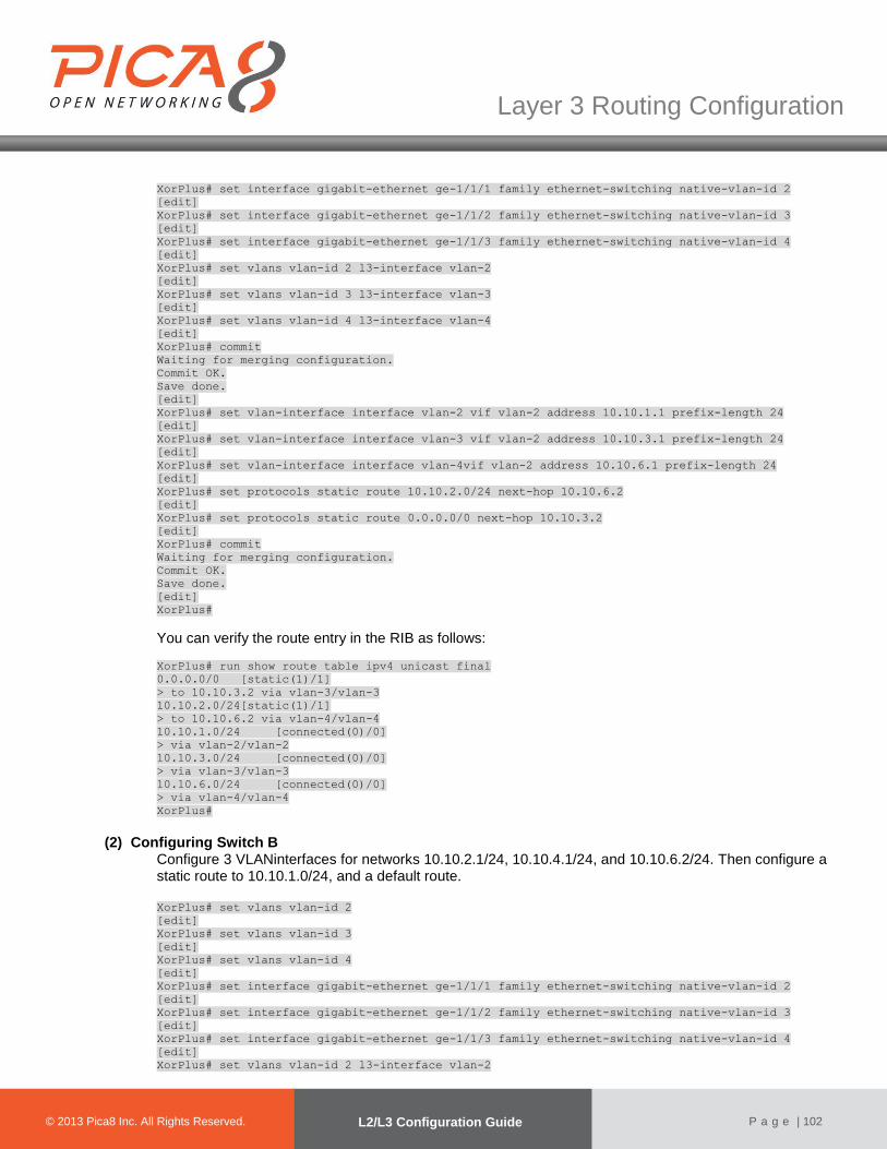
© 2012 Pica8 Inc. All © 2012 Pica8 Inc. All
Layer 3 Routing Configuration
© 2013 Pica8 Inc. All Rights Reserved. L2/L3 Configuration Guide
P a g e | 102
XorPlus# set interface gigabit-ethernet ge-1/1/1 family ethernet-switching native-vlan-id 2
[edit]
XorPlus# set interface gigabit-ethernet ge-1/1/2 family ethernet-switching native-vlan-id 3
[edit]
XorPlus# set interface gigabit-ethernet ge-1/1/3 family ethernet-switching native-vlan-id 4
[edit]
XorPlus# set vlans vlan-id 2 l3-interface vlan-2
[edit]
XorPlus# set vlans vlan-id 3 l3-interface vlan-3
[edit]
XorPlus# set vlans vlan-id 4 l3-interface vlan-4
[edit]
XorPlus# commit
Waiting for merging configuration.
Commit OK.
Save done.
[edit]
XorPlus# set vlan-interface interface vlan-2 vif vlan-2 address 10.10.1.1 prefix-length 24
[edit]
XorPlus# set vlan-interface interface vlan-3 vif vlan-2 address 10.10.3.1 prefix-length 24
[edit]
XorPlus# set vlan-interface interface vlan-4vif vlan-2 address 10.10.6.1 prefix-length 24
[edit]
XorPlus# set protocols static route 10.10.2.0/24 next-hop 10.10.6.2
[edit]
XorPlus# set protocols static route 0.0.0.0/0 next-hop 10.10.3.2
[edit]
XorPlus# commit
Waiting for merging configuration.
Commit OK.
Save done.
[edit]
XorPlus#
You can verify the route entry in the RIB as follows:
XorPlus# run show route table ipv4 unicast final
0.0.0.0/0 [static(1)/1]
> to 10.10.3.2 via vlan-3/vlan-3
10.10.2.0/24[static(1)/1]
> to 10.10.6.2 via vlan-4/vlan-4
10.10.1.0/24 [connected(0)/0]
> via vlan-2/vlan-2
10.10.3.0/24 [connected(0)/0]
> via vlan-3/vlan-3
10.10.6.0/24 [connected(0)/0]
> via vlan-4/vlan-4
XorPlus#
(2) Configuring Switch B Configure 3 VLANinterfaces for networks 10.10.2.1/24, 10.10.4.1/24, and 10.10.6.2/24. Then configure a static route to 10.10.1.0/24, and a default route. XorPlus# set vlans vlan-id 2
[edit]
XorPlus# set vlans vlan-id 3
[edit]
XorPlus# set vlans vlan-id 4
[edit]
XorPlus# set interface gigabit-ethernet ge-1/1/1 family ethernet-switching native-vlan-id 2
[edit]
XorPlus# set interface gigabit-ethernet ge-1/1/2 family ethernet-switching native-vlan-id 3
[edit]
XorPlus# set interface gigabit-ethernet ge-1/1/3 family ethernet-switching native-vlan-id 4
[edit]
XorPlus# set vlans vlan-id 2 l3-interface vlan-2

© 2012 Pica8 Inc. All © 2012 Pica8 Inc. All
Layer 3 Routing Configuration
© 2013 Pica8 Inc. All Rights Reserved. L2/L3 Configuration Guide
P a g e | 103
[edit]
XorPlus# set vlans vlan-id 3 l3-interface vlan-3
[edit]
XorPlus# set vlans vlan-id 4 l3-interface vlan-4
[edit]
XorPlus# commit
Waiting for merging configuration.
Commit OK.
Save done.
[edit]
XorPlus# set vlan-interface interface vlan-2 vif vlan-2 address 10.10.2.1 prefix-length 24
[edit]
XorPlus# set vlan-interface interface vlan-3 vif vlan-2 address 10.10.4.1 prefix-length 24
[edit]
XorPlus# set vlan-interface interface vlan-4vif vlan-2 address 10.10.6.1 prefix-length 24
[edit]
XorPlus# set protocols static route 10.10.1.0/24 next-hop 10.10.6.1
[edit]
XorPlus# set protocols static route 0.0.0.0/0 next-hop 10.10.4.2
[edit]
XorPlus# commit
Waiting for merging configuration.
Commit OK.
Save done.
[edit]
XorPlus#
You can verify the route entry in the RIB:
XorPlus# run show route table ipv4 unicast final
0.0.0.0/0 [static(1)/1]
> to 10.10.4.2 via vlan-3/vlan-3
10.10.1.0/24[static(1)/1]
> to 10.10.6.1 via vlan-4/vlan-4
10.10.2.0/24 [connected(0)/0]
> via vlan-2/vlan-2
10.10.4.0/24 [connected(0)/0]
> via vlan-3/vlan-3
10.10.6.0/24 [connected(0)/0]
> via vlan-4/vlan-4
XorPlus#
(3) Configuring Switch C Configure 3 VLANinterfaces for networks 10.10.3.2/24, 10.10.4.2/24, and 10.10.5.2/24. Then configure a static route to 10.10.1.0/24, and a default route. XorPlus# set vlans vlan-id 2
[edit]
XorPlus# set vlans vlan-id 3
[edit]
XorPlus# set vlans vlan-id 4
[edit]
XorPlus# set interface gigabit-ethernet ge-1/1/1 family ethernet-switching native-vlan-id 2
[edit]
XorPlus# set interface gigabit-ethernet ge-1/1/2 family ethernet-switching native-vlan-id 3
[edit]
XorPlus# set interface gigabit-ethernet ge-1/1/3 family ethernet-switching native-vlan-id 4
[edit]
XorPlus# set vlans vlan-id 2 l3-interface vlan-2
[edit]
XorPlus# set vlans vlan-id 3 l3-interface vlan-3
[edit]
XorPlus# set vlans vlan-id 4 l3-interface vlan-4
[edit]
XorPlus# commit
Waiting for merging configuration.
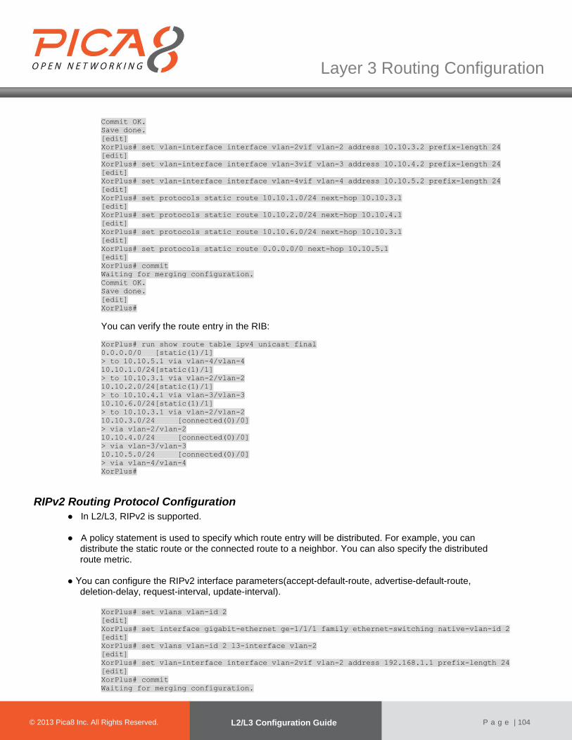
© 2012 Pica8 Inc. All © 2012 Pica8 Inc. All
Layer 3 Routing Configuration
© 2013 Pica8 Inc. All Rights Reserved. L2/L3 Configuration Guide
P a g e | 104
Commit OK.
Save done.
[edit]
XorPlus# set vlan-interface interface vlan-2vif vlan-2 address 10.10.3.2 prefix-length 24
[edit]
XorPlus# set vlan-interface interface vlan-3vif vlan-3 address 10.10.4.2 prefix-length 24
[edit]
XorPlus# set vlan-interface interface vlan-4vif vlan-4 address 10.10.5.2 prefix-length 24
[edit]
XorPlus# set protocols static route 10.10.1.0/24 next-hop 10.10.3.1
[edit]
XorPlus# set protocols static route 10.10.2.0/24 next-hop 10.10.4.1
[edit]
XorPlus# set protocols static route 10.10.6.0/24 next-hop 10.10.3.1
[edit]
XorPlus# set protocols static route 0.0.0.0/0 next-hop 10.10.5.1
[edit]
XorPlus# commit
Waiting for merging configuration.
Commit OK.
Save done.
[edit]
XorPlus#
You can verify the route entry in the RIB:
XorPlus# run show route table ipv4 unicast final
0.0.0.0/0 [static(1)/1]
> to 10.10.5.1 via vlan-4/vlan-4
10.10.1.0/24[static(1)/1]
> to 10.10.3.1 via vlan-2/vlan-2
10.10.2.0/24[static(1)/1]
> to 10.10.4.1 via vlan-3/vlan-3
10.10.6.0/24[static(1)/1]
> to 10.10.3.1 via vlan-2/vlan-2
10.10.3.0/24 [connected(0)/0]
> via vlan-2/vlan-2
10.10.4.0/24 [connected(0)/0]
> via vlan-3/vlan-3
10.10.5.0/24 [connected(0)/0]
> via vlan-4/vlan-4
XorPlus#
RIPv2 Routing Protocol Configuration
● In L2/L3, RIPv2 is supported.
● A policy statement is used to specify which route entry will be distributed. For example, you can distribute the static route or the connected route to a neighbor. You can also specify the distributed route metric.
● You can configure the RIPv2 interface parameters(accept-default-route, advertise-default-route,
deletion-delay, request-interval, update-interval).
XorPlus# set vlans vlan-id 2
[edit]
XorPlus# set interface gigabit-ethernet ge-1/1/1 family ethernet-switching native-vlan-id 2
[edit]
XorPlus# set vlans vlan-id 2 l3-interface vlan-2
[edit]
XorPlus# set vlan-interface interface vlan-2vif vlan-2 address 192.168.1.1 prefix-length 24
[edit]
XorPlus# commit
Waiting for merging configuration.

© 2012 Pica8 Inc. All © 2012 Pica8 Inc. All
Layer 3 Routing Configuration
© 2013 Pica8 Inc. All Rights Reserved. L2/L3 Configuration Guide
P a g e | 105
Commit OK.
Save done.
[edit]
XorPlus# set vlans vlan-id 3
[edit]
XorPlus# set vlans vlan-id 3 l3-interface vlan-3
[edit]
XorPlus# set interface gigabit-ethernet ge-1/1/2 family ethernet-switching native-vlan-id 3
[edit]
XorPlus# set vlan-interface interface vlan-3vif vlan-3 address 192.168.2.1 prefix-length 24
[edit]
XorPlus# set protocols static route 9.9.9.0/24 next-hop 192.168.2.2
[edit]
XorPlus# commit
Waiting for merging configuration.
Commit OK.
Save done.
[edit]
XorPlus# set policy policy-statement connected-to-rip term export from protocol connected
[edit]
XorPlus# set policy policy-statement connected-to-rip term export then metric 0
[edit]
XorPlus# set policy policy-statement static-to-rip term export from protocol static
[edit]
XorPlus# set policy policy-statement static-to-rip term export then metric 1
[edit]
XorPlus# commit
Waiting for merging configuration.
Commit OK.
Save done.
[edit]
XorPlus# set protocols rip interface vlan-2vif vlan-2 address 192.168.1.1
[edit]
XorPlus# set protocols rip export "connected-to-rip,static-to-rip"
[edit]
XorPlus# commit
Waiting for merging configuration.
Commit OK.
Save done.
[edit]
XorPlus# You can verify the RIP configuration: XorPlus# run show rip status all
* RIP on vlan-2vlan-2 192.168.1.1
Status: enabled
XorPlus#
XorPlus# run show rip statistics all
* RIP on vlan-2vlan-2 192.168.1.1
Status: enabled
Counter Value
-------------------------------- ----------------
Requests Sent 7
Updates Sent 6
Triggered Updates Sent 1
Non-RIP Updates Sent 0
Total Packets Received 0
Request Packets Received 0
Update Packets Received 0
Bad Packets Received 0
Authentication Failures 0
Bad Routes Received 0
Non-RIP Requests Received 0
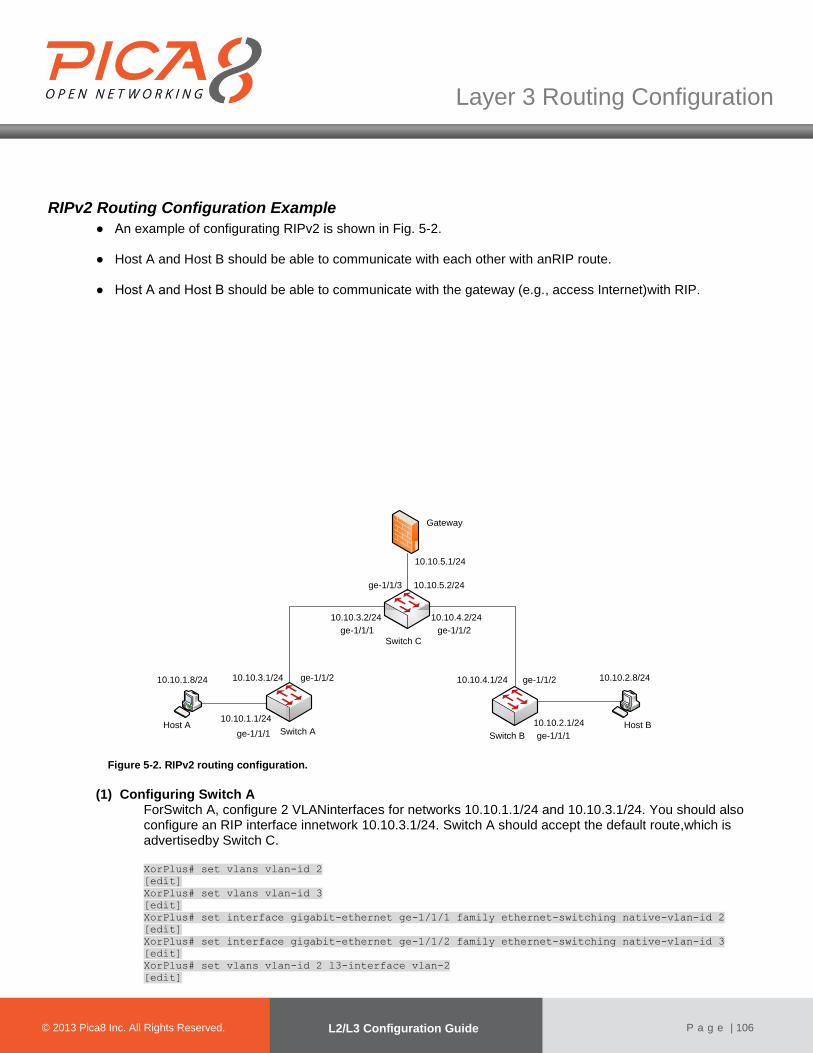
© 2012 Pica8 Inc. All © 2012 Pica8 Inc. All
Layer 3 Routing Configuration
© 2013 Pica8 Inc. All Rights Reserved. L2/L3 Configuration Guide
P a g e | 106
RIPv2 Routing Configuration Example
● An example of configurating RIPv2 is shown in Fig. 5-2. ● Host A and Host B should be able to communicate with each other with anRIP route. ● Host A and Host B should be able to communicate with the gateway (e.g., access Internet)with RIP.
Switch ASwitch B
Switch C
Gateway
Host A Host B10.10.1.1/24
10.10.2.1/24
10.10.3.1/24
10.10.3.2/24
10.10.4.1/24
10.10.4.2/24
10.10.5.2/24
ge-1/1/1 ge-1/1/1
ge-1/1/2ge-1/1/2
ge-1/1/1 ge-1/1/2
ge-1/1/3
10.10.5.1/24
10.10.2.8/2410.10.1.8/24
Figure 5-2. RIPv2 routing configuration.
(1) Configuring Switch A
ForSwitch A, configure 2 VLANinterfaces for networks 10.10.1.1/24 and 10.10.3.1/24. You should also configure an RIP interface innetwork 10.10.3.1/24. Switch A should accept the default route,which is advertisedby Switch C.
XorPlus# set vlans vlan-id 2
[edit]
XorPlus# set vlans vlan-id 3
[edit]
XorPlus# set interface gigabit-ethernet ge-1/1/1 family ethernet-switching native-vlan-id 2
[edit]
XorPlus# set interface gigabit-ethernet ge-1/1/2 family ethernet-switching native-vlan-id 3
[edit]
XorPlus# set vlans vlan-id 2 l3-interface vlan-2
[edit]

© 2012 Pica8 Inc. All © 2012 Pica8 Inc. All
Layer 3 Routing Configuration
© 2013 Pica8 Inc. All Rights Reserved. L2/L3 Configuration Guide
P a g e | 107
XorPlus# set vlans vlan-id 3 l3-interface vlan-3
[edit]
XorPlus# set vlan-interface interface vlan-2vif vlan-2 address 10.10.1.1 prefix-length 24
[edit]
XorPlus# set vlan-interface interface vlan-3vif vlan-3 address 10.10.3.1 prefix-length 24
[edit]
XorPlus# commit
Waiting for merging configuration.
Commit OK.
Save done.
[edit]
XorPlus# set policy policy-statement connected-to-rip term export from protocol connected
[edit]
XorPlus# set policy policy-statement connected-to-rip term export then metric 0
[edit]
XorPlus# commit
Waiting for merging configuration.
Commit OK.
Save done.
[edit]
XorPlus# set protocols rip interface vlan-3 address 10.10.3.1
[edit]
XorPlus# set protocols rip export "connected-to-rip"
[edit]
XorPlus# set protocols rip interface vlan-3vif vlan-3 address 10.10.3.1 accept-default-route true
[edit]
XorPlus# commit
Waiting for merging configuration.
Commit OK.
Save done.
[edit]
XorPlus#
(2) Configuring Switch B Configure 2 VLANinterfaces for networks 10.10.1.1/24 and 10.10.3.1/24. Then configure an RIP interface in network 10.10.3.1/24. Switch B should accept the default route,which is advertisedby Switch C.
XorPlus# set vlans vlan-id 2
[edit]
XorPlus# set vlans vlan-id 3
[edit]
XorPlus# set interface gigabit-ethernet ge-1/1/1 family ethernet-switching native-vlan-id 2
[edit]
XorPlus# set interface gigabit-ethernet ge-1/1/2 family ethernet-switching native-vlan-id 3
[edit]
XorPlus# set vlans vlan-id 2 l3-interface vlan-2
[edit]
XorPlus# set vlans vlan-id 3 l3-interface vlan-3
[edit]
XorPlus# set vlan-interface interface vlan-2vif vlan-2 address 10.10.2.1 prefix-length 24
[edit]
XorPlus# set vlan-interface interface vlan-3vif vlan-2 address 10.10.4.1 prefix-length 24
[edit]
XorPlus# commit
Waiting for merging configuration.
Commit OK.
Save done.
[edit]
XorPlus# set policy policy-statement connected-to-rip term export from protocol connected
[edit]
XorPlus# set policy policy-statement connected-to-rip term export then metric 0
[edit]
XorPlus# commit
Waiting for merging configuration.
Commit OK.
Save done.
[edit]
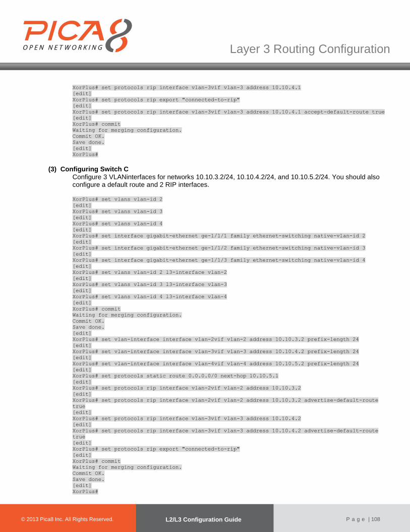
© 2012 Pica8 Inc. All © 2012 Pica8 Inc. All
Layer 3 Routing Configuration
© 2013 Pica8 Inc. All Rights Reserved. L2/L3 Configuration Guide
P a g e | 108
XorPlus# set protocols rip interface vlan-3vif vlan-3 address 10.10.4.1
[edit]
XorPlus# set protocols rip export "connected-to-rip"
[edit]
XorPlus# set protocols rip interface vlan-3vif vlan-3 address 10.10.4.1 accept-default-route true
[edit]
XorPlus# commit
Waiting for merging configuration.
Commit OK.
Save done.
[edit]
XorPlus#
(3) Configuring Switch C Configure 3 VLANinterfaces for networks 10.10.3.2/24, 10.10.4.2/24, and 10.10.5.2/24. You should also configure a default route and 2 RIP interfaces.
XorPlus# set vlans vlan-id 2
[edit]
XorPlus# set vlans vlan-id 3
[edit]
XorPlus# set vlans vlan-id 4
[edit]
XorPlus# set interface gigabit-ethernet ge-1/1/1 family ethernet-switching native-vlan-id 2
[edit]
XorPlus# set interface gigabit-ethernet ge-1/1/2 family ethernet-switching native-vlan-id 3
[edit]
XorPlus# set interface gigabit-ethernet ge-1/1/3 family ethernet-switching native-vlan-id 4
[edit]
XorPlus# set vlans vlan-id 2 l3-interface vlan-2
[edit]
XorPlus# set vlans vlan-id 3 l3-interface vlan-3
[edit]
XorPlus# set vlans vlan-id 4 l3-interface vlan-4
[edit]
XorPlus# commit
Waiting for merging configuration.
Commit OK.
Save done.
[edit]
XorPlus# set vlan-interface interface vlan-2vif vlan-2 address 10.10.3.2 prefix-length 24
[edit]
XorPlus# set vlan-interface interface vlan-3vif vlan-3 address 10.10.4.2 prefix-length 24
[edit]
XorPlus# set vlan-interface interface vlan-4vif vlan-4 address 10.10.5.2 prefix-length 24
[edit]
XorPlus# set protocols static route 0.0.0.0/0 next-hop 10.10.5.1
[edit]
XorPlus# set protocols rip interface vlan-2vif vlan-2 address 10.10.3.2
[edit]
XorPlus# set protocols rip interface vlan-2vif vlan-2 address 10.10.3.2 advertise-default-route
true
[edit]
XorPlus# set protocols rip interface vlan-3vif vlan-3 address 10.10.4.2
[edit]
XorPlus# set protocols rip interface vlan-3vif vlan-3 address 10.10.4.2 advertise-default-route
true
[edit]
XorPlus# set protocols rip export "connected-to-rip"
[edit]
XorPlus# commit
Waiting for merging configuration.
Commit OK.
Save done.
[edit]
XorPlus#

© 2012 Pica8 Inc. All © 2012 Pica8 Inc. All
Layer 3 Routing Configuration
© 2013 Pica8 Inc. All Rights Reserved. L2/L3 Configuration Guide
P a g e | 109
(4) Verifying the RIP Configuration You can verify the RIP configuration of the switchesas shown below. (In our example, weverify the RIP peer and the RIP route table in Switch A.) XorPlus# run show rip peer
Address Interface State Hello Rx Hello Tx Last Hello
--------------- --------------- ------ ---------- ---------- ----------
10.10.3.2vlan-3/vlan-3 Up 0 0 00:41:44
XorPlus#
XorPlus# run show route table ipv4 unicast rip
0.0.0.0/0[rip(120)/1]
> to 10.10.3.2 via vlan-3/vlan-3
10.10.2.0/24 [rip(120)/1]
> to 10.10.3.2 via vlan-3/vlan-3
10.10.4.0/24 [rip(120)/1]
> to 10.10.3.2 via vlan-3/vlan-3
OSPF Routing Protocol Configuration
●In L2/L3, OSPFv2 is supported. ●XorPlus supports normal areas, stub areas, and not-so-stubby areas (NSSAs)in OSPF.
(1) Configuring the router ID
The router ID should be configured first when you configure OSPF. The router ID is a string similar to the IP address, and should be unique in the OSPF domain. You should not change the router IDafter completing the configuration.
XorPlus# set protocols ospf4 router-id 1.1.1.1
[edit]
XorPlus# commit
Waiting for merging configuration.
Commit OK.
Save done.
[edit]
(2) Configuringan OSPF area and area-type Area 0.0.0.0 is the backbone area of OSPF; each OSPF domain should have the area 0.0.0.0. Area types include normal, stub, and NSSA. XorPlus# set protocols ospf4 area 0.0.0.0 area-type normal
[edit]
XorPlus# set protocols ospf4 area 1.1.1.1 area-type stub
[edit]
XorPlus# set protocols ospf4 area 2.2.2.2 area-type nssa
[edit]
XorPlus# commit
Waiting for merging configuration.
Commit OK.
Save done.
[edit]
XorPlus#
(3) Configuring OSPF interfaces After configuringan OSPF area, configure OSPF interfaces in the area. These interfaces will transmit and receive LSAs to calculate the route. XorPlus# set vlans vlan-id 2 l3-interface vlan-2
[edit]
XorPlus# set vlans vlan-id 3 l3-interface vlan-3
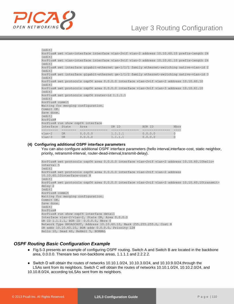
© 2012 Pica8 Inc. All © 2012 Pica8 Inc. All
Layer 3 Routing Configuration
© 2013 Pica8 Inc. All Rights Reserved. L2/L3 Configuration Guide
P a g e | 110
[edit]
XorPlus# set vlan-interface interface vlan-2vif vlan-2 address 10.10.60.10 prefix-length 24
[edit]
XorPlus# set vlan-interface interface vlan-3vif vlan-3 address 10.10.61.10 prefix-length 24
[edit]
XorPlus# set interface gigabit-ethernet ge-1/1/1 family ethernet-switching native-vlan-id 2
[edit]
XorPlus# set interface gigabit-ethernet ge-1/1/2 family ethernet-switching native-vlan-id 3
[edit]
XorPlus# set protocols ospf4 area 0.0.0.0 interface vlan-2vif vlan-2 address 10.10.60.10
[edit]
XorPlus# set protocols ospf4 area 0.0.0.0 interface vlan-3vif vlan-3 address 10.10.61.10
[edit]
XorPlus# set protocols ospf4 router-id 1.1.1.1
[edit]
XorPlus# commit
Waiting for merging configuration.
Commit OK.
Save done.
[edit]
XorPlus#
XorPlus# run show ospf4 interface
Interface State Area DR ID BDR ID Nbrs
--------- -------- --------------- --------------- --------------- ----
vlan-2 DR 0.0.0.0 1.1.1.1 0.0.0.0 0
vlan-3 DR 0.0.0.0 1.1.1.1 0.0.0.0 0
(4) Configuring additional OSPF interface parameters You can also configure additional OSPF interface parameters (hello interval,interface-cost, static neighbor, priority, retransmit-interval, router-dead-interval,transmit-delay).
XorPlus# set protocols ospf4 area 0.0.0.0 interface vlan-2vif vlan-2 address 10.10.60.10hello-
interval 5
[edit]
XorPlus# set protocols ospf4 area 0.0.0.0 interface vlan-2vif vlan-2 address
10.10.60.10interface-cost 8
[edit]
XorPlus# set protocols ospf4 area 0.0.0.0 interface vlan-2vif vlan-2 address 10.10.60.10transmit-
delay 2
[edit]
XorPlus# commit
Waiting for merging configuration.
Commit OK.
Save done.
[edit]
XorPlus#
XorPlus# run show ospf4 interface detail
Interface vlan-2/vlan-2, State DR, Area 0.0.0.0
DR ID 1.1.1.1, BDR ID 0.0.0.0, Nbrs 0
Network Type BROADCAST, Address 10.10.60.10, Mask 255.255.255.0, Cost 8
DR addr 10.10.60.10, BDR addr 0.0.0.0, Priority 128
Hello 10, Dead 40, ReXmit 5, NORMAL
OSPF Routing Basic Configuration Example
● Fig.5-3 presents an example of configuring OSPF routing. Switch A and Switch B are located in the backbone area, 0.0.0.0. Thereare two non-backbone areas, 1.1.1.1 and 2.2.2.2.
● Switch D will obtain the routes of networks 10.10.1.0/24, 10.10.3.0/24, and 10.10.9.0/24,through the
LSAs sent from its neighbors. Switch C will obtain the routes of networks 10.10.1.0/24, 10.10.2.0/24, and 10.10.8.0/24, according toLSAs sent from its neighbors.
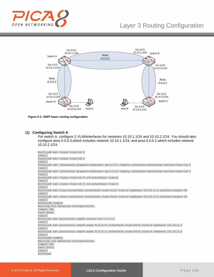
© 2012 Pica8 Inc. All © 2012 Pica8 Inc. All
Layer 3 Routing Configuration
© 2013 Pica8 Inc. All Rights Reserved. L2/L3 Configuration Guide
P a g e | 111
Host A
Area
0.0.0.1
Area
0.0.0.0
Area
0.0.0.2
Switch A
Switch B
Switch CSwitch D
Ge-1/1/1
10.10.2.2/24
Ge-1/1/2
10.10.2.1/24
Ge-1/1/1
10.10.1.1/24
Ge-1/1/1
10.10.1.2/24
Ge-1/1/2
10.10.3.1/24
Ge-1/1/1
10.10.3.2/24
Host BGe-1/1/2
10.10.8.1/24Ge-1/1/2
10.10.9.1/24 Figure 5-3. OSPF basic routing configuration.
(1) Configuring Switch A For switch A, configure 2 VLANinterfaces for networks 10.10.1.1/24 and 10.10.2.1/24. You should also configure area 0.0.0.0,which includes network 10.10.1.1/24, and area 0.0.0.1,which includes network 10.10.2.1/24. XorPlus# set vlans vlan-id 2
[edit]
XorPlus# set vlans vlan-id 3
[edit]
XorPlus# set interface gigabit-ethernet ge-1/1/1 family ethernet-switching native-vlan-id 2
[edit]
XorPlus# set interface gigabit-ethernet ge-1/1/2 family ethernet-switching native-vlan-id 3
[edit]
XorPlus# set vlans vlan-id 2 l3-interface vlan-2
[edit]
XorPlus# set vlans vlan-id 3 l3-interface vlan-3
[edit]
XorPlus# set vlan-interface interface vlan-2vif vlan-2 address 10.10.1.1 prefix-length 24
[edit]
XorPlus# set vlan-interface interface vlan-3vif vlan-3 address 10.10.2.1 prefix-length 24
[edit]
XorPlus# commit
Waiting for merging configuration.
Commit OK.
Save done.
[edit]
XorPlus# set protocols ospf4 router-id 1.1.1.1
[edit]
XorPlus# set protocols ospf4 area 0.0.0.0 interface vlan-2vif vlan-2 address 10.10.1.1
[edit]
XorPlus# set protocols ospf4 area 0.0.0.1 interface vlan-3vif vlan-3 address 10.10.2.1
[edit]
XorPlus# commit
Waiting for merging configuration.
Commit OK.
Save done.
[edit]
XorPlus#

© 2012 Pica8 Inc. All © 2012 Pica8 Inc. All
Layer 3 Routing Configuration
© 2013 Pica8 Inc. All Rights Reserved. L2/L3 Configuration Guide
P a g e | 112
(2) Configuring Switch B Configure 2 VLANinterfaces for networks 10.10.1.2/24 and 10.10.3.1/24. Then configure area 0.0.0.0, which includes network 10.10.1.2/24, and area 0.0.0.3,which includesnetwork 10.10.3.1/24. XorPlus# set vlans vlan-id 2
[edit]
XorPlus# set vlans vlan-id 3
[edit]
XorPlus# set interface gigabit-ethernet ge-1/1/1 family ethernet-switching native-vlan-id 2
[edit]
XorPlus# set interface gigabit-ethernet ge-1/1/2 family ethernet-switching native-vlan-id 3
[edit]
XorPlus# set vlans vlan-id 2 l3-interface vlan-2
[edit]
XorPlus# set vlans vlan-id 3 l3-interface vlan-3
[edit]
XorPlus# set vlan-interface interface vlan-2vif vlan-2 address 10.10.1.2 prefix-length 24
[edit]
XorPlus# set vlan-interface interface vlan-3vif vlan-3 address 10.10.3.1 prefix-length 24
[edit]
XorPlus# commit
Waiting for merging configuration.
Commit OK.
Save done.
[edit]
XorPlus# set protocols ospf4 router-id 2.2.2.2
[edit]
XorPlus# set protocols ospf4 area 0.0.0.0 interface vlan-2vif vlan-2 address 10.10.1.2
[edit]
XorPlus# set protocols ospf4 area 0.0.0.2 interface vlan-3vif vlan-3 address 10.10.3.1
[edit]
XorPlus# commit
Waiting for merging configuration.
Commit OK.
Save done.
[edit]
XorPlus#
(3) Configuring Switch C Configure just one OSPF interface, in area 0.0.0.2. XorPlus# set vlans vlan-id 2
[edit]
XorPlus# set vlans vlan-id 3
[edit]
XorPlus# set interface gigabit-ethernet ge-1/1/1 family ethernet-switching native-vlan-id 2
[edit]
XorPlus# set interface gigabit-ethernet ge-1/1/2 family ethernet-switching native-vlan-id 3
[edit]
XorPlus# set vlans vlan-id 2 l3-interface vlan-2
[edit]
XorPlus# set vlans vlan-id 3 l3-interface vlan-3
[edit]
XorPlus# set vlan-interface interface vlan-2vif vlan-2 address 10.10.3.2 prefix-length 24
[edit]
XorPlus# set vlan-interface interface vlan-3vif vlan-3 address 10.10.9.1 prefix-length 24
[edit]
XorPlus# commit
Waiting for merging configuration.
Commit OK.
Save done.
[edit]
XorPlus# set protocols ospf4 router-id 3.3.3.3
[edit]
XorPlus# set protocols ospf4 area 0.0.0.2 interface vlan-2vif vlan-2 address 10.10.3.2
[edit]

© 2012 Pica8 Inc. All © 2012 Pica8 Inc. All
Layer 3 Routing Configuration
© 2013 Pica8 Inc. All Rights Reserved. L2/L3 Configuration Guide
P a g e | 113
XorPlus# commit
Waiting for merging configuration.
Commit OK.
Save done.
[edit]
XorPlus#
(4) Configuring Switch D Configure just one OSPF interface, in area 0.0.0.1. XorPlus# set vlans vlan-id 2
[edit]
XorPlus# set vlans vlan-id 3
[edit]
XorPlus# set interface gigabit-ethernet ge-1/1/1 family ethernet-switching native-vlan-id 2
[edit]
XorPlus# set interface gigabit-ethernet ge-1/1/2 family ethernet-switching native-vlan-id 3
[edit]
XorPlus# set vlans vlan-id 2 l3-interface vlan-2
[edit]
XorPlus# set vlans vlan-id 3 l3-interface vlan-3
[edit]
XorPlus# set vlan-interface interface vlan-2vif vlan-2 address 10.10.2.2 prefix-length 24
[edit]
XorPlus# set vlan-interface interface vlan-3vif vlan-3 address 10.10.8.1 prefix-length 24
[edit]
XorPlus# commit
Waiting for merging configuration.
Commit OK.
Save done.
[edit]
XorPlus# set protocols ospf4 router-id 4.4.4.4
[edit]
XorPlus# set protocols ospf4 area 0.0.0.1 interface vlan-2vif vlan-2 address 10.10.2.2
[edit]
XorPlus# commit
Waiting for merging configuration.
Commit OK.
Save done.
[edit]
XorPlus#
(5) Verifying the OSPFconfiguration You can verify the OSPF configuration of a switch by checkingits OSPF neighbor. Below, switch A has two OSPF neighbor interfaces, 10.10.1.2 and 10.10.2.2. XorPlus# run show ospf4 neighbor
Address Interface State Router ID Pri Dead
--------------- --------------------- -------- --------------- ----- ----
10.10.1.2vlan-2/vlan-2 Full 2.2.2.2 1 32
10.10.2.2vlan-3/vlan-3 Full 4.4.4.4 1 32
Thencheck the OSPF database as shown below: XorPlus# run show ospf4 database
OSPF link state database, Area 0.0.0.0
Type ID Adv Rtr Seq Age Opt Cksum Len
------- ---------------- --------------- ---------- ---- --- ------ ---
Router *1.1.1.1 1.1.1.1 0x8000025a 394 0x2 0xf2bb 48
Network *10.10.1.1 1.1.1.1 0x80000180 394 0x2 0xc0b9 32
Network *10.10.2.1 1.1.1.1 0x80000180 394 0x2 0xc0b9 32
Router 2.2.2.2 2.2.2.2 0x8000023e 339 0x2 0x3024 36
Network 10.10.3.1 2.2.2.2 0x80000180 394 0x2 0xc0b9 32
Router 3.3.3.33.3.3.3 0x8000023e 339 0x2 0x3024 36
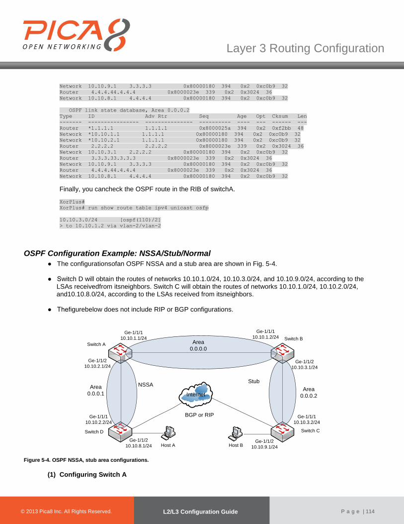
© 2012 Pica8 Inc. All © 2012 Pica8 Inc. All
Layer 3 Routing Configuration
© 2013 Pica8 Inc. All Rights Reserved. L2/L3 Configuration Guide
P a g e | 114
Network 10.10.9.1 3.3.3.3 0x80000180 394 0x2 0xc0b9 32
Router 4.4.4.44.4.4.4 0x8000023e 339 0x2 0x3024 36
Network 10.10.8.1 4.4.4.4 0x80000180 394 0x2 0xc0b9 32
OSPF link state database, Area 0.0.0.2
Type ID Adv Rtr Seq Age Opt Cksum Len
------- ---------------- --------------- ---------- ---- --- ------ ---
Router *1.1.1.1 1.1.1.1 0x8000025a 394 0x2 0xf2bb 48
Network *10.10.1.1 1.1.1.1 0x80000180 394 0x2 0xc0b9 32
Network *10.10.2.1 1.1.1.1 0x80000180 394 0x2 0xc0b9 32
Router 2.2.2.2 2.2.2.2 0x8000023e 339 0x2 0x3024 36
Network 10.10.3.1 2.2.2.2 0x80000180 394 0x2 0xc0b9 32
Router 3.3.3.33.3.3.3 0x8000023e 339 0x2 0x3024 36
Network 10.10.9.1 3.3.3.3 0x80000180 394 0x2 0xc0b9 32
Router 4.4.4.44.4.4.4 0x8000023e 339 0x2 0x3024 36
Network 10.10.8.1 4.4.4.4 0x80000180 394 0x2 0xc0b9 32
Finally, you cancheck the OSPF route in the RIB of switchA.
XorPlus#
XorPlus# run show route table ipv4 unicast osfp
10.10.3.0/24 [ospf(110)/2]
> to 10.10.1.2 via vlan-2/vlan-2
OSPF Configuration Example: NSSA/Stub/Normal
● The configurationsofan OSPF NSSA and a stub area are shown in Fig. 5-4. ● Switch D will obtain the routes of networks 10.10.1.0/24, 10.10.3.0/24, and 10.10.9.0/24, according to the
LSAs receivedfrom itsneighbors. Switch C will obtain the routes of networks 10.10.1.0/24, 10.10.2.0/24, and10.10.8.0/24, according to the LSAs received from itsneighbors.
● Thefigurebelow does not include RIP or BGP configurations.
Internet
Host A
Area
0.0.0.1
Area
0.0.0.0
Area
0.0.0.2
Switch A
Switch B
Switch CSwitch D
Ge-1/1/1
10.10.2.2/24
Ge-1/1/2
10.10.2.1/24
Ge-1/1/1
10.10.1.1/24
Ge-1/1/1
10.10.1.2/24
Ge-1/1/2
10.10.3.1/24
Ge-1/1/1
10.10.3.2/24
Host BGe-1/1/2
10.10.8.1/24Ge-1/1/2
10.10.9.1/24
NSSAStub
BGP or RIP
Figure 5-4. OSPF NSSA, stub area configurations.
(1) Configuring Switch A

© 2012 Pica8 Inc. All © 2012 Pica8 Inc. All
Layer 3 Routing Configuration
© 2013 Pica8 Inc. All Rights Reserved. L2/L3 Configuration Guide
P a g e | 115
For switch A, configure 2 VLANinterfaces for networks 10.10.1.1/24 and 10.10.2.1/24. Youshould also configure area 0.0.0.0,which includes network 10.10.1.1/24,and area 0.0.0.1,which includes network 10.10.2.1/24. XorPlus# set vlans vlan-id 2
[edit]
XorPlus# set vlans vlan-id 3
[edit]
XorPlus# set interface gigabit-ethernet ge-1/1/1 family ethernet-switching native-vlan-id 2
[edit]
XorPlus# set interface gigabit-ethernet ge-1/1/2 family ethernet-switching native-vlan-id 3
[edit]
XorPlus# set vlans vlan-id 2 l3-interface vlan-2
[edit]
XorPlus# set vlans vlan-id 3 l3-interface vlan-3
[edit]
XorPlus# set vlan-interface interface vlan-2vif vlan-2 address 10.10.1.1 prefix-length 24
[edit]
XorPlus# set vlan-interface interface vlan-3vif vlan-3 address 10.10.2.1 prefix-length 24
[edit]
XorPlus# commit
Waiting for merging configuration.
Commit OK.
Save done.
[edit]
XorPlus# set protocols ospf4 router-id 1.1.1.1
[edit]
XorPlus# set protocols ospf4 area 0.0.0.0 interface vlan-2vif vlan-2 address 10.10.1.1
[edit]
XorPlus# set protocols ospf4 area 0.0.0.1 interface vlan-3vif vlan-3 address 10.10.2.1
[edit]
XorPlus# set protocols ospf4 area 0.0.0.1 area-type nssa
[edit]
XorPlus# commit
Waiting for merging configuration.
Commit OK.
Save done.
[edit]
XorPlus#
(2) Configuring Switch B Configure 2 VLANinterfaces for networks 10.10.1.2/24 and 10.10.3.1/24. Then configure area 0.0.0.0,which includes network 10.10.1.2/24, and stub area 0.0.0.3,which includes network 10.10.3.1/24. XorPlus# set vlans vlan-id 2
[edit]
XorPlus# set vlans vlan-id 3
[edit]
XorPlus# set interface gigabit-ethernet ge-1/1/1 family ethernet-switching native-vlan-id 2
[edit]
XorPlus# set interface gigabit-ethernet ge-1/1/2 family ethernet-switching native-vlan-id 3
[edit]
XorPlus# set vlans vlan-id 2 l3-interface vlan-2
[edit]
XorPlus# set vlans vlan-id 3 l3-interface vlan-3
[edit]
XorPlus# set vlan-interface interface vlan-2vif vlan-2 address 10.10.1.2 prefix-length 24
[edit]
XorPlus# set vlan-interface interface vlan-3vif vlan-3 address 10.10.3.1 prefix-length 24
[edit]
XorPlus# commit
Waiting for merging configuration.
Commit OK.
Save done.
[edit]
XorPlus# set protocols ospf4 router-id 2.2.2.2

© 2012 Pica8 Inc. All © 2012 Pica8 Inc. All
Layer 3 Routing Configuration
© 2013 Pica8 Inc. All Rights Reserved. L2/L3 Configuration Guide
P a g e | 116
[edit]
XorPlus# set protocols ospf4 area 0.0.0.0 interface vlan-2vif vlan-2 address 10.10.1.2
[edit]
XorPlus# set protocols ospf4 area 0.0.0.2 interface vlan-3vif vlan-3 address 10.10.3.1
[edit]
XorPlus# set protocols ospf4 area 0.0.0.2area-type stub
[edit]
XorPlus# commit
Waiting for merging configuration.
Commit OK.
Save done.
[edit]
XorPlus#
(3) Configuring Switch C Configure just one OSPF interface, in area 0.0.0.2. XorPlus# set vlans vlan-id 2
[edit]
XorPlus# set vlans vlan-id 3
[edit]
XorPlus# set interface gigabit-ethernet ge-1/1/1 family ethernet-switching native-vlan-id 2
[edit]
XorPlus# set interface gigabit-ethernet ge-1/1/2 family ethernet-switching native-vlan-id 3
[edit]
XorPlus# set vlans vlan-id 2 l3-interface vlan-2
[edit]
XorPlus# set vlans vlan-id 3 l3-interface vlan-3
[edit]
XorPlus# set vlan-interface interface vlan-2vif vlan-2 address 10.10.3.2 prefix-length 24
[edit]
XorPlus# set vlan-interface interface vlan-3vif vlan-3 address 10.10.9.1 prefix-length 24
[edit]
XorPlus# commit
Waiting for merging configuration.
Commit OK.
Save done.
[edit]
XorPlus# set protocols ospf4 router-id 3.3.3.3
[edit]
XorPlus# set protocols ospf4 area 0.0.0.2 interface vlan-2vif vlan-2 address 10.10.3.2
[edit]
XorPlus# set protocols ospf4 area 0.0.0.2area-type stub
[edit]
XorPlus# commit
Waiting for merging configuration.
Commit OK.
Save done.
[edit]
XorPlus#
(4) Configuring Switch D Configure just one OSPF interface, in area 0.0.0.1. Switch D should import the RIPor BGP routefrom theRIB, and distribute it to other areas. XorPlus# set vlans vlan-id 2
[edit]
XorPlus# set vlans vlan-id 3
[edit]
XorPlus# set interface gigabit-ethernet ge-1/1/1 family ethernet-switching native-vlan-id 2
[edit]
XorPlus# set interface gigabit-ethernet ge-1/1/2 family ethernet-switching native-vlan-id 3
[edit]
XorPlus# set vlans vlan-id 2 l3-interface vlan-2
[edit]
XorPlus# set vlans vlan-id 3 l3-interface vlan-3
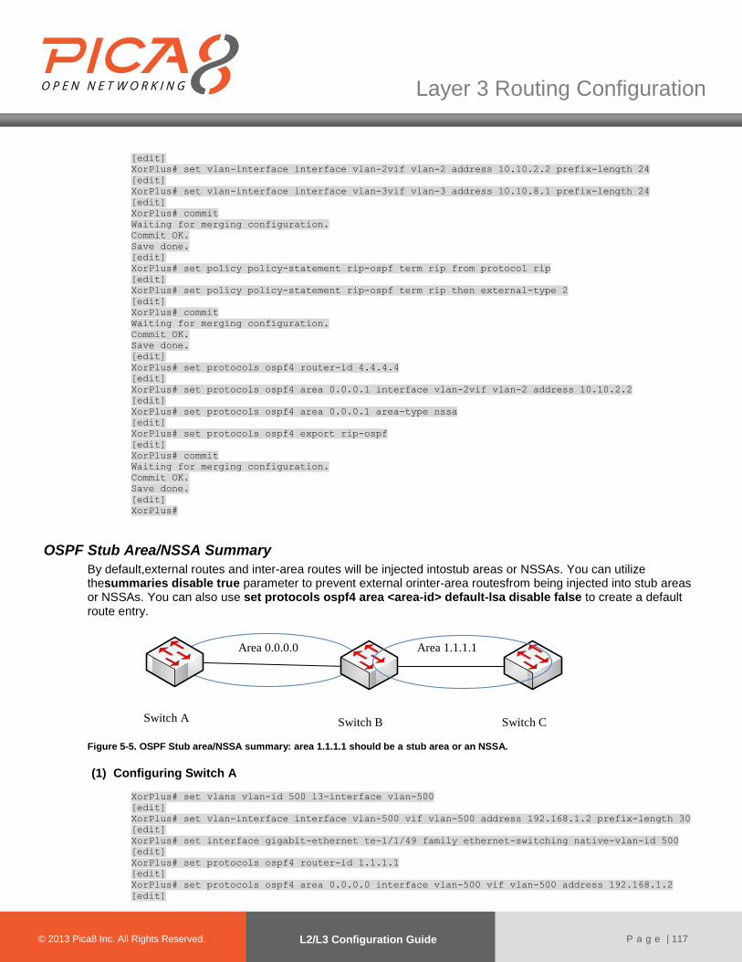
© 2012 Pica8 Inc. All © 2012 Pica8 Inc. All
Layer 3 Routing Configuration
© 2013 Pica8 Inc. All Rights Reserved. L2/L3 Configuration Guide
P a g e | 117
[edit]
XorPlus# set vlan-interface interface vlan-2vif vlan-2 address 10.10.2.2 prefix-length 24
[edit]
XorPlus# set vlan-interface interface vlan-3vif vlan-3 address 10.10.8.1 prefix-length 24
[edit]
XorPlus# commit
Waiting for merging configuration.
Commit OK.
Save done.
[edit]
XorPlus# set policy policy-statement rip-ospf term rip from protocol rip
[edit]
XorPlus# set policy policy-statement rip-ospf term rip then external-type 2
[edit]
XorPlus# commit
Waiting for merging configuration.
Commit OK.
Save done.
[edit]
XorPlus# set protocols ospf4 router-id 4.4.4.4
[edit]
XorPlus# set protocols ospf4 area 0.0.0.1 interface vlan-2vif vlan-2 address 10.10.2.2
[edit]
XorPlus# set protocols ospf4 area 0.0.0.1 area-type nssa
[edit]
XorPlus# set protocols ospf4 export rip-ospf
[edit]
XorPlus# commit
Waiting for merging configuration.
Commit OK.
Save done.
[edit]
XorPlus#
OSPF Stub Area/NSSA Summary
By default,external routes and inter-area routes will be injected intostub areas or NSSAs. You can utilize thesummaries disable true parameter to prevent external orinter-area routesfrom being injected into stub areas or NSSAs. You can also use set protocols ospf4 area <area-id> default-lsa disable false to create a default route entry.
Figure 5-5. OSPF Stub area/NSSA summary: area 1.1.1.1 should be a stub area or an NSSA.
(1) Configuring Switch A
XorPlus# set vlans vlan-id 500 l3-interface vlan-500
[edit]
XorPlus# set vlan-interface interface vlan-500 vif vlan-500 address 192.168.1.2 prefix-length 30
[edit]
XorPlus# set interface gigabit-ethernet te-1/1/49 family ethernet-switching native-vlan-id 500
[edit]
XorPlus# set protocols ospf4 router-id 1.1.1.1
[edit]
XorPlus# set protocols ospf4 area 0.0.0.0 interface vlan-500 vif vlan-500 address 192.168.1.2
[edit]
Switch A Switch B Switch C
Area 0.0.0.0 Area 1.1.1.1

© 2012 Pica8 Inc. All © 2012 Pica8 Inc. All
Layer 3 Routing Configuration
© 2013 Pica8 Inc. All Rights Reserved. L2/L3 Configuration Guide
P a g e | 118
XorPlus# commit
[edit]
Waiting for merging configuration.
Commit OK.
Save Done.
[edit]
XorPlus#
OSPF Virtual Link Configuration Guide
●Thesinglebackbone area (area 0.0.0.0) cannot be disconnected,or certain areas of the Autonomous System will become unreachable. To establish and maintain connectivity of the backbone, virtual links can be configured through non-backbone areas. Virtual links serve to connect physically separate components of the backbone.
● The two endpoints of a virtual link are Area Border Routers (ARBs). The virtual link must be configured in both
routers. The configuration information in each router consists of the other virtual endpoint (the other ARB), and the non-backbone area that the two routers have in common (called the transit area). Virtual links cannot be configured through stub areas.
● Enable OSPF on Switchs A, B, C, and D at the beginning. There is no route entry from the backbone area
(0.0.0.0) to area 2.2.2.2.
Figure 5-7. Virtual link configuration.
(1) Configuring Switch A
XorPlus# set vlans vlan-id 500 l3-interface vlan-500
[edit]
XorPlus# set vlan-interface interface vlan-500 vif vlan-500 address 192.168.1.2 prefix-length 30
[edit]
XorPlus# set interface gigabit-ethernet ge-1/1/47 family ethernet-switching native-vlan-id 500
[edit]
XorPlus# set protocols ospf4 router-id 1.1.1.1
[edit]
XorPlus# set protocols ospf4 area 0.0.0.0 interface vlan-500 vif vlan-500 address 192.168.1.2
[edit]
XorPlus#commit
[edit]
Waiting for merging configuration.
Commit OK.
Save Done.
[edit]
XorPlus#
(2) Configuring Switch B
XorPlus# set vlans vlan-id 400 l3-interface vlan-400
[edit]
Switch A
Switch B
Switch C
Switch D
Area 0.0.0.0 Area 1.1.1.1 Area 2.2.2.2
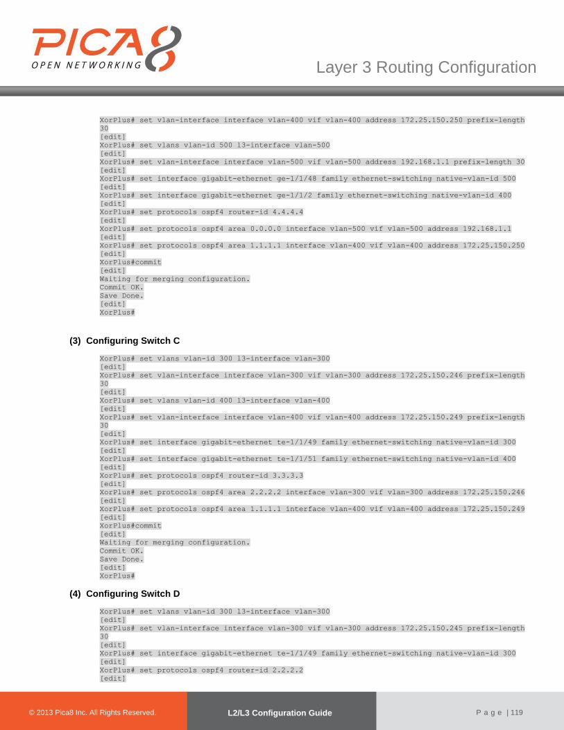
© 2012 Pica8 Inc. All © 2012 Pica8 Inc. All
Layer 3 Routing Configuration
© 2013 Pica8 Inc. All Rights Reserved. L2/L3 Configuration Guide
P a g e | 119
XorPlus# set vlan-interface interface vlan-400 vif vlan-400 address 172.25.150.250 prefix-length
30
[edit]
XorPlus# set vlans vlan-id 500 l3-interface vlan-500
[edit]
XorPlus# set vlan-interface interface vlan-500 vif vlan-500 address 192.168.1.1 prefix-length 30
[edit]
XorPlus# set interface gigabit-ethernet ge-1/1/48 family ethernet-switching native-vlan-id 500
[edit]
XorPlus# set interface gigabit-ethernet ge-1/1/2 family ethernet-switching native-vlan-id 400
[edit]
XorPlus# set protocols ospf4 router-id 4.4.4.4
[edit]
XorPlus# set protocols ospf4 area 0.0.0.0 interface vlan-500 vif vlan-500 address 192.168.1.1
[edit]
XorPlus# set protocols ospf4 area 1.1.1.1 interface vlan-400 vif vlan-400 address 172.25.150.250
[edit]
XorPlus#commit
[edit]
Waiting for merging configuration.
Commit OK.
Save Done.
[edit]
XorPlus#
(3) Configuring Switch C
XorPlus# set vlans vlan-id 300 l3-interface vlan-300
[edit]
XorPlus# set vlan-interface interface vlan-300 vif vlan-300 address 172.25.150.246 prefix-length
30
[edit]
XorPlus# set vlans vlan-id 400 l3-interface vlan-400
[edit]
XorPlus# set vlan-interface interface vlan-400 vif vlan-400 address 172.25.150.249 prefix-length
30
[edit]
XorPlus# set interface gigabit-ethernet te-1/1/49 family ethernet-switching native-vlan-id 300
[edit]
XorPlus# set interface gigabit-ethernet te-1/1/51 family ethernet-switching native-vlan-id 400
[edit]
XorPlus# set protocols ospf4 router-id 3.3.3.3
[edit]
XorPlus# set protocols ospf4 area 2.2.2.2 interface vlan-300 vif vlan-300 address 172.25.150.246
[edit]
XorPlus# set protocols ospf4 area 1.1.1.1 interface vlan-400 vif vlan-400 address 172.25.150.249
[edit]
XorPlus#commit
[edit]
Waiting for merging configuration.
Commit OK.
Save Done.
[edit]
XorPlus#
(4) Configuring Switch D
XorPlus# set vlans vlan-id 300 l3-interface vlan-300
[edit]
XorPlus# set vlan-interface interface vlan-300 vif vlan-300 address 172.25.150.245 prefix-length
30
[edit]
XorPlus# set interface gigabit-ethernet te-1/1/49 family ethernet-switching native-vlan-id 300
[edit]
XorPlus# set protocols ospf4 router-id 2.2.2.2
[edit]

© 2012 Pica8 Inc. All © 2012 Pica8 Inc. All
Layer 3 Routing Configuration
© 2013 Pica8 Inc. All Rights Reserved. L2/L3 Configuration Guide
P a g e | 120
XorPlus# set protocols ospf4 area 2.2.2.2 interface vlan-300 vif vlan-300 address 172.25.150.245
[edit]
XorPlus#commit
[edit]
Waiting for merging configuration.
Commit OK.
Save Done.
[edit]
XorPlus#
Enable virtual links on the Area Border Routers (Switch B and Switch C).After this step, there will be aroute entry from the backbone area, 0.0.0.0, to area 2.2.2.2.
(1) Configuring Switch B
XorPlus# set protocols ospf6 area 0.0.0.0 virtual-link 3.3.3.3 transmit-area 1.1.1.1
XorPlus#commit
[edit]
Waiting for merging configuration.
Commit OK.
Save Done.
[edit]
XorPlus#
(2) Configuring Switch C
XorPlus# set protocols ospf6 area 0.0.0.0 virtual-link 4.4.4.4 transmit-area 1.1.1.1
XorPlus#commit
[edit]
Waiting for merging configuration.
Commit OK.
Save Done.
[edit]
XorPlus#
(3) Checkingan IPv6 OSPF
# Check ipv6 ospf neighbor on Switch B
XorPlus# run show ospf4 neighbor
Address Interface State Router ID Pri Dead
--------------- --------------------- -------- --------------- ----- ----
192.168.1.2 vlan-500/vlan-500 Full 1.1.1.1 128 34
172.25.150.249 vlan-400/vlan-400 Full 3.3.3.3 128 36
172.25.150.249 vlink/3.3.3.3 Init 3.3.3.3 0 0
(2) Configuring Switch B
XorPlus# set vlans vlan-id 500 l3-interface vlan-500
[edit]
XorPlus# set vlan-interface interface vlan-500 vif vlan-500 address 192.168.1.1 prefix-length 30
[edit]
XorPlus# set interface gigabit-ethernet te-1/1/49 family ethernet-switching native-vlan-id 500
[edit]
XorPlus# set protocols ospf4 router-id 4.4.4.4
[edit]
XorPlus# set protocols ospf4 area 0.0.0.0 interface vlan-100 vif vlan-500 address 192.168.1.1
[edit]
XorPlus# set vlans vlan-id 400 l3-interface vlan-400
[edit]
XorPlus# set vlan-interface interface vlan-400 vif vlan-400 address 172.25.150.250 prefix-length
30
[edit]
XorPlus# set interface gigabit-ethernet te-1/1/49 family ethernet-switching native-vlan-id 400
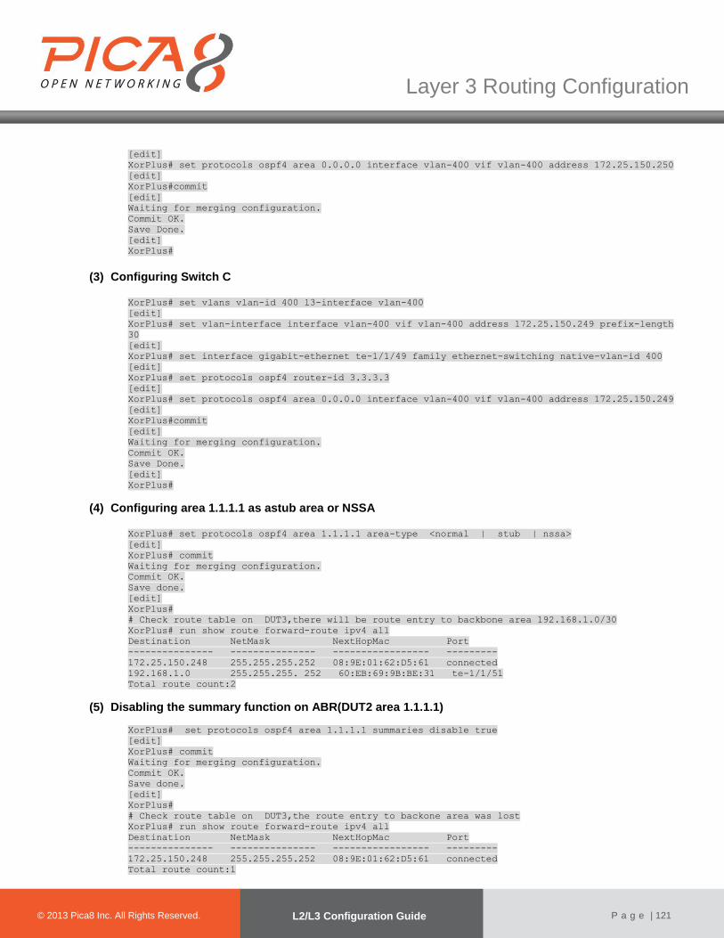
© 2012 Pica8 Inc. All © 2012 Pica8 Inc. All
Layer 3 Routing Configuration
© 2013 Pica8 Inc. All Rights Reserved. L2/L3 Configuration Guide
P a g e | 121
[edit]
XorPlus# set protocols ospf4 area 0.0.0.0 interface vlan-400 vif vlan-400 address 172.25.150.250
[edit]
XorPlus#commit
[edit]
Waiting for merging configuration.
Commit OK.
Save Done.
[edit]
XorPlus#
(3) Configuring Switch C XorPlus# set vlans vlan-id 400 l3-interface vlan-400
[edit]
XorPlus# set vlan-interface interface vlan-400 vif vlan-400 address 172.25.150.249 prefix-length
30
[edit]
XorPlus# set interface gigabit-ethernet te-1/1/49 family ethernet-switching native-vlan-id 400
[edit]
XorPlus# set protocols ospf4 router-id 3.3.3.3
[edit]
XorPlus# set protocols ospf4 area 0.0.0.0 interface vlan-400 vif vlan-400 address 172.25.150.249
[edit]
XorPlus#commit
[edit]
Waiting for merging configuration.
Commit OK.
Save Done.
[edit]
XorPlus#
(4) Configuring area 1.1.1.1 as astub area or NSSA
XorPlus# set protocols ospf4 area 1.1.1.1 area-type <normal | stub | nssa>
[edit]
XorPlus# commit
Waiting for merging configuration.
Commit OK.
Save done.
[edit]
XorPlus#
# Check route table on DUT3,there will be route entry to backbone area 192.168.1.0/30
XorPlus# run show route forward-route ipv4 all
Destination NetMask NextHopMac Port
--------------- --------------- ----------------- ---------
172.25.150.248 255.255.255.252 08:9E:01:62:D5:61 connected
192.168.1.0 255.255.255. 252 60:EB:69:9B:BE:31 te-1/1/51
Total route count:2
(5) Disabling the summary function on ABR(DUT2 area 1.1.1.1)
XorPlus# set protocols ospf4 area 1.1.1.1 summaries disable true
[edit]
XorPlus# commit
Waiting for merging configuration.
Commit OK.
Save done.
[edit]
XorPlus#
# Check route table on DUT3,the route entry to backone area was lost
XorPlus# run show route forward-route ipv4 all
Destination NetMask NextHopMac Port
--------------- --------------- ----------------- ---------
172.25.150.248 255.255.255.252 08:9E:01:62:D5:61 connected
Total route count:1
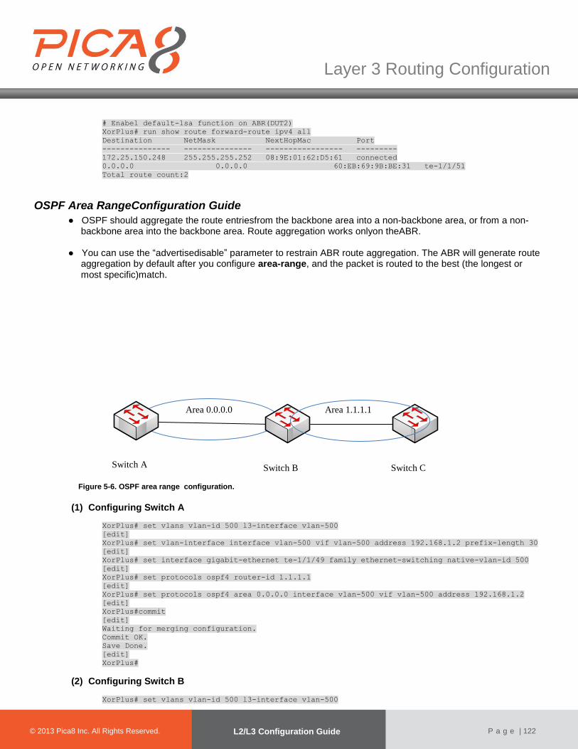
© 2012 Pica8 Inc. All © 2012 Pica8 Inc. All
Layer 3 Routing Configuration
© 2013 Pica8 Inc. All Rights Reserved. L2/L3 Configuration Guide
P a g e | 122
# Enabel default-lsa function on ABR(DUT2)
XorPlus# run show route forward-route ipv4 all
Destination NetMask NextHopMac Port
--------------- --------------- ----------------- ---------
172.25.150.248 255.255.255.252 08:9E:01:62:D5:61 connected
0.0.0.0 0.0.0.0 60:EB:69:9B:BE:31 te-1/1/51
Total route count:2
OSPF Area RangeConfiguration Guide
● OSPF should aggregate the route entriesfrom the backbone area into a non-backbone area, or from a non-backbone area into the backbone area. Route aggregation works onlyon theABR.
● You can use the “advertisedisable” parameter to restrain ABR route aggregation. The ABR will generate route
aggregation by default after you configure area-range, and the packet is routed to the best (the longest or most specific)match.
Figure 5-6. OSPF area range configuration.
(1) Configuring Switch A
XorPlus# set vlans vlan-id 500 l3-interface vlan-500
[edit]
XorPlus# set vlan-interface interface vlan-500 vif vlan-500 address 192.168.1.2 prefix-length 30
[edit]
XorPlus# set interface gigabit-ethernet te-1/1/49 family ethernet-switching native-vlan-id 500
[edit]
XorPlus# set protocols ospf4 router-id 1.1.1.1
[edit]
XorPlus# set protocols ospf4 area 0.0.0.0 interface vlan-500 vif vlan-500 address 192.168.1.2
[edit]
XorPlus#commit
[edit]
Waiting for merging configuration.
Commit OK.
Save Done.
[edit]
XorPlus#
(2) Configuring Switch B
XorPlus# set vlans vlan-id 500 l3-interface vlan-500
Switch A Switch B Switch C
Area 0.0.0.0 Area 1.1.1.1
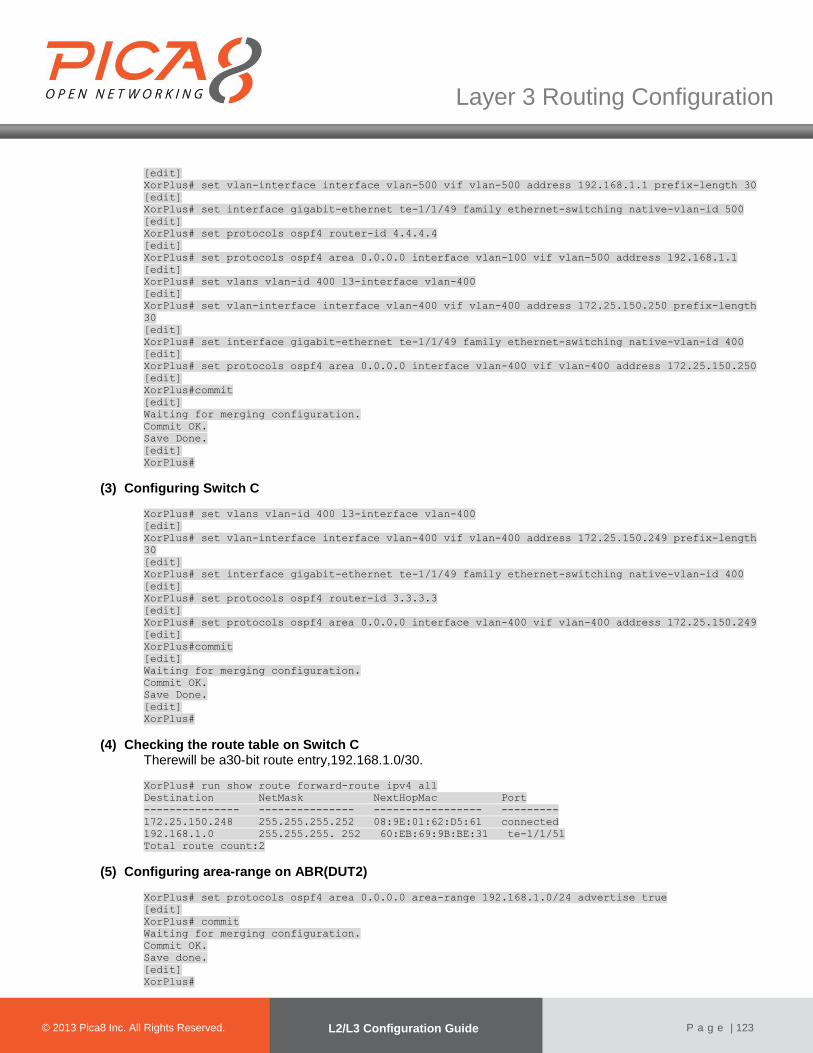
© 2012 Pica8 Inc. All © 2012 Pica8 Inc. All
Layer 3 Routing Configuration
© 2013 Pica8 Inc. All Rights Reserved. L2/L3 Configuration Guide
P a g e | 123
[edit]
XorPlus# set vlan-interface interface vlan-500 vif vlan-500 address 192.168.1.1 prefix-length 30
[edit]
XorPlus# set interface gigabit-ethernet te-1/1/49 family ethernet-switching native-vlan-id 500
[edit]
XorPlus# set protocols ospf4 router-id 4.4.4.4
[edit]
XorPlus# set protocols ospf4 area 0.0.0.0 interface vlan-100 vif vlan-500 address 192.168.1.1
[edit]
XorPlus# set vlans vlan-id 400 l3-interface vlan-400
[edit]
XorPlus# set vlan-interface interface vlan-400 vif vlan-400 address 172.25.150.250 prefix-length
30
[edit]
XorPlus# set interface gigabit-ethernet te-1/1/49 family ethernet-switching native-vlan-id 400
[edit]
XorPlus# set protocols ospf4 area 0.0.0.0 interface vlan-400 vif vlan-400 address 172.25.150.250
[edit]
XorPlus#commit
[edit]
Waiting for merging configuration.
Commit OK.
Save Done.
[edit]
XorPlus#
(3) Configuring Switch C
XorPlus# set vlans vlan-id 400 l3-interface vlan-400
[edit]
XorPlus# set vlan-interface interface vlan-400 vif vlan-400 address 172.25.150.249 prefix-length
30
[edit]
XorPlus# set interface gigabit-ethernet te-1/1/49 family ethernet-switching native-vlan-id 400
[edit]
XorPlus# set protocols ospf4 router-id 3.3.3.3
[edit]
XorPlus# set protocols ospf4 area 0.0.0.0 interface vlan-400 vif vlan-400 address 172.25.150.249
[edit]
XorPlus#commit
[edit]
Waiting for merging configuration.
Commit OK.
Save Done.
[edit]
XorPlus#
(4) Checking the route table on Switch C Therewill be a30-bit route entry,192.168.1.0/30.
XorPlus# run show route forward-route ipv4 all
Destination NetMask NextHopMac Port
--------------- --------------- ----------------- ---------
172.25.150.248 255.255.255.252 08:9E:01:62:D5:61 connected
192.168.1.0 255.255.255. 252 60:EB:69:9B:BE:31 te-1/1/51
Total route count:2
(5) Configuring area-range on ABR(DUT2)
XorPlus# set protocols ospf4 area 0.0.0.0 area-range 192.168.1.0/24 advertise true
[edit]
XorPlus# commit
Waiting for merging configuration.
Commit OK.
Save done.
[edit]
XorPlus#

© 2012 Pica8 Inc. All © 2012 Pica8 Inc. All
Layer 3 Routing Configuration
© 2013 Pica8 Inc. All Rights Reserved. L2/L3 Configuration Guide
P a g e | 124
(6) Checking the route table on DUT3 The route entry 192.168.1.0/30 will be replaced by 192.168.1.0/24.
XorPlus# run show route forward-route ipv4 all
Destination NetMask NextHopMac Port
--------------- --------------- ----------------- ---------
172.25.150.248 255.255.255.252 08:9E:01:62:D5:61 connected
192.168.1.0 255.255.255. 0 60:EB:69:9B:BE:31 te-1/1/51
Total route count:2
Importing anExternal Route into an OSPF Area
Figure 5-8. Importing an external route into an OSPF area.
(1) Configuring Switch A
XorPlus# set vlans vlan-id 500 l3-interface vlan-500
[edit]
XorPlus# set vlan-interface interface vlan-500 vif vlan-500 address 192.168.1.2 prefix-length 30
[edit]
XorPlus# set interface gigabit-ethernet ge-1/1/47 family ethernet-switching native-vlan-id 500
[edit]
XorPlus# set protocols ospf4 router-id 1.1.1.1
[edit]
XorPlus# set protocols ospf4 area 0.0.0.0 interface vlan-500 vif vlan-500 address 192.168.1.2
[edit]
XorPlus#commit
[edit]
Waiting for merging configuration.
Commit OK.
Save Done.
[edit]
XorPlus#
(2) Configuring Switch B
XorPlus# set vlans vlan-id 400 l3-interface vlan-400
[edit]
XorPlus# set vlan-interface interface vlan-400 vif vlan-400 address 172.25.150.250 prefix-length
30
[edit]
XorPlus# set vlans vlan-id 500 l3-interface vlan-500
[edit]
XorPlus# set vlan-interface interface vlan-500 vif vlan-500 address 192.168.1.1 prefix-length 30
[edit]
XorPlus# set interface gigabit-ethernet ge-1/1/48 family ethernet-switching native-vlan-id 500
[edit]
XorPlus# set interface gigabit-ethernet ge-1/1/2 family ethernet-switching native-vlan-id 400
[edit]
XorPlus# set protocols ospf4 router-id 4.4.4.4
[edit]
XorPlus# set protocols ospf4 area 0.0.0.0 interface vlan-500 vif vlan-500 address 192.168.1.1
[edit]
XorPlus# set protocols ospf4 area 1.1.1.1 interface vlan-400 vif vlan-400 address 172.25.150.250
[edit]
Area 1.1.1.1 Area 0.0.0.0
Switch A
Switch B
Switch C
Switch D

© 2012 Pica8 Inc. All © 2012 Pica8 Inc. All
Layer 3 Routing Configuration
© 2013 Pica8 Inc. All Rights Reserved. L2/L3 Configuration Guide
P a g e | 125
XorPlus#commit
[edit]
Waiting for merging configuration.
Commit OK.
Save Done.
[edit]
XorPlus#
(3) Configuring Switch C
XorPlus# set vlans vlan-id 300 l3-interface vlan-300
[edit]
XorPlus# set vlan-interface interface vlan-300 vif vlan-300 address 172.25.150.246 prefix-length
30
[edit]
XorPlus# set vlans vlan-id 400 l3-interface vlan-400
[edit]
XorPlus# set vlan-interface interface vlan-400 vif vlan-400 address 172.25.150.249 prefix-length
30
[edit]
XorPlus# set interface gigabit-ethernet te-1/1/49 family ethernet-switching native-vlan-id 300
[edit]
XorPlus# set interface gigabit-ethernet te-1/1/51 family ethernet-switching native-vlan-id 400
[edit]
XorPlus# set protocols ospf4 router-id 3.3.3.3
[edit]
XorPlus# set protocols ospf4 area 2.2.2.2 interface vlan-300 vif vlan-300 address 172.25.150.246
[edit]
XorPlus# set protocols ospf4 area 1.1.1.1 interface vlan-400 vif vlan-400 address 172.25.150.249
[edit]
XorPlus#commit
[edit]
Waiting for merging configuration.
Commit OK.
Save Done.
[edit]
XorPlus#
(4) Configuring an external route import policy on Switch C
# Configure external static route.
XorPlus# set protocols static route 192.168.6.0/24 next-hop 172.25.150.245
[edit]
XorPlus# commit
Waiting for merging configuration.
Commit OK.
Save done.
[edit]
XorPlus#
# Configure policy to import external route
XorPlus# set policy policy-statement static term 1 from protocol static
[edit]
XorPlus# set policy policy-statement static then accept
[edit]
XorPlus# commit
Waiting for merging configuration.
Commit OK.
Save done.
[edit]
XorPlus#
# Using policy on ospf
XorPlus# set protocols ospf4 export static
[edit]
XorPlus# commit
Waiting for merging configuration.
Commit OK.
Save done.

© 2012 Pica8 Inc. All © 2012 Pica8 Inc. All
Layer 3 Routing Configuration
© 2013 Pica8 Inc. All Rights Reserved. L2/L3 Configuration Guide
P a g e | 126
[edit]
XorPlus#
# Check route table on Switch A , there will be route entry 192.168.6.0/24
XorPlus# run show route forward-route ipv4 all
Destination NetMask NextHopMac Port
--------------- --------------- ----------------- ---------
192.168.1.0 255.255.255.252 C8:0A:A9:AE:0A:66 connected
172.25.150.248 255.255.255.252 60:EB:69:9B:BE:31 te-1/1/47
192.168.6.0 255.255.255.0 60:EB:69:9B:BE:31 te-1/1/47
Total route count:3
BFD Protocol Configuration
●BFD supports for OSPF, BGP, static route and ECMP.
(5) Configuring the mode There are two BFD modes: active and passive. The BFD will send protocol messages initiatively in active mode, and passively in passive mode.
XorPlus# set protocols bfd mode active
[edit]
XorPlus# commit
Merging the configuration.
Commit OK.
Save done.
[edit]
XorPlus# set protocols bfd mode passive
[edit]
XorPlus# commit
Commit OK.
Save done.
[edit]
XorPlus#
(6) Configuring detect-multiplier, min-receive-interval and min-transmit-interval Detect-multiplier: a detection timeout multiple, it is used in calculating detection timeout time by the detector; min-receive-interval: the minimum sending interval of the BFD packet supported by the local side; min-transmit-interval: the minimum receiving interval of the BFD packet supported by the local side.. XorPlus# set protocols bfd interface vlan25 detect-multiplier 5
[edit]
XorPlus# set protocols bfd interface vlan25 min-transmit-interval 1000
[edit]
XorPlus# set protocols bfd interface vlan25 min-receive-interval 2000
[edit]
XorPlus# commit
Merging the configuration.
Commit OK.
Save done.
[edit]
XorPlus#
(7) Enable BFD on L3 interface Enable BFD on the VLAN interface. XorPlus# set protocols bfd interface vlan25 disable false
[edit]
XorPlus# commit
Commit OK.
Save done.
[edit]
XorPlus#

© 2012 Pica8 Inc. All © 2012 Pica8 Inc. All
Layer 3 Routing Configuration
© 2013 Pica8 Inc. All Rights Reserved. L2/L3 Configuration Guide
P a g e | 127
(8) Enable BFD supporting for OSPF4 Enable BFD to support for protocol OSPF4. XorPlus# set protocols ospf4 area 1.1.1.1 interface vlan-25 vif vlan-25 address 125.125.25.6 bfd
disable false
[edit]
XorPlus# commit
Merging the configuration.
Commit OK.
Save done.
[edit]
XorPlus#
(9) Enable BFD supporting for OSPF6 Enable BFD to support for protocol OSPF6. XorPlus# set protocols ospf6 area 1.1.1.1 interface vlan-23 vif vlan-23 bfd disable false
[edit]
XorPlus# commit
Merging the configuration.
Commit OK.
Save done.
[edit]
XorPlus#
(10) Enable BFD supporting for BGP Enable BFD to support for protocol BGP. XorPlus# set protocols bgp peer 125.125.25.1 bfd disable false
[edit]
XorPlus# commit
Merging the configuration.
Commit OK.
Save done.
[edit]
XorPlus#
(11) Enable BFD supporting for static route Enable BFD to support for protocol static route. XorPlus# set protocols static route 201.201.20.0/24 next-hop 113.113.13.1
[edit]
XorPlus# set protocols static route 201.201.20.0/24 bfd true
[edit]
XorPlus# commit
Commit OK.
Save done.
[edit]
XorPlus#
(12) Enable BFD supporting for ECMP Enable BFD to support for protocol ECMP. XorPlus# set protocols static route 201.201.20.0/24 next-hop 113.113.13.1
[edit]
XorPlus# set protocols static route 201.201.20.0/24 bfd true
[edit]
XorPlus# commit
Commit OK.
Save done.
[edit]
XorPlus# set protocols static route 201.201.20.0/24 qualified-next-hop 115.115.15.1 bfd true
[edit]

© 2012 Pica8 Inc. All © 2012 Pica8 Inc. All
Layer 3 Routing Configuration
© 2013 Pica8 Inc. All Rights Reserved. L2/L3 Configuration Guide
P a g e | 128
XorPlus# set protocols static route 201.201.20.0/24 qualified-next-hop 115.115.15.1 metric 1
[edit]
XorPlus# commit
Commit OK.
Save done.
[edit]
XorPlus#
BFD Basic Configuration Example
● Fig.5-9 presents an example of configuring BFD supporting for OSPF4 . Switch A and Switch B are located in the backbone area, 0.0.0.0.
Area
0.0.0.0
Switch A
Ge-1/1/1
123.123.10.6/24
Switch B
123.123.10.1/24
Ge-1/1/1
Figure 5-9. BFD basic configuration.
(6) Configuring Switch A For switch A, configure one VLAN interface for networks 123.123.10.1/24. You should also configure area 0.0.0.0,which includes network 123.123.10.1/24 and 123.123.10.6/24, and enable BFD on OSPF4 and VLAN interface. XorPlus# set vlans vlan-id 10
[edit]
XorPlus# set vlans vlan-id 10 l3-interface vlan10
[edit]
XorPlus# set interface gigabit-ethernet ge-1/1/1 family ethernet-switching native-vlan-id 10
[edit]
XorPlus# set vlan-interface interface vlan10 vif vlan10 address 123.123.10.1 prefix-length 24
[edit]
XorPlus# commit
Merging the configuration.
Commit OK.
Save done.
[edit]
XorPlus# set protocols ospf4 router-id 1.1.1.1
[edit]
XorPlus# set protocols ospf4 area 0.0.0.0 interface vlan10 vif vlan10 address 123.123.10.1 bfd
disable false
[edit]
XorPlus# commit
Merging the configuration.
Commit OK.
Save done.
[edit]
XorPlus# set protocols bfd interface vlan10 disable false
[edit]
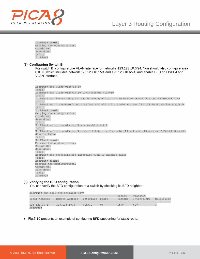
© 2012 Pica8 Inc. All © 2012 Pica8 Inc. All
Layer 3 Routing Configuration
© 2013 Pica8 Inc. All Rights Reserved. L2/L3 Configuration Guide
P a g e | 129
XorPlus# commit
Merging the configuration.
Commit OK.
Save done.
[edit]
XorPlus#
(7) Configuring Switch B For switch B, configure one VLAN interface for networks 123.123.10.6/24. You should also configure area 0.0.0.0,which includes network 123.123.10.1/24 and 123.123.10.6/24, and enable BFD on OSPF4 and VLAN interface. . XorPlus# set vlans vlan-id 10
[edit]
XorPlus# set vlans vlan-id 10 l3-interface vlan-10
[edit]
XorPlus# set interface gigabit-ethernet ge-1/1/1 family ethernet-switching native-vlan-id 10
[edit]
XorPlus# set vlan-interface interface vlan-10 vif vlan-10 address 123.123.10.6 prefix-length 24
[edit]
XorPlus# commit
Merging the configuration.
Commit OK.
Save done.
[edit]
XorPlus# set protocols ospf4 router-id 2.2.2.2
[edit]
XorPlus# set protocols ospf4 area 0.0.0.0 interface vlan-10 vif vlan-10 address 123.123.10.6 bfd
disable false
[edit]
XorPlus# commit
Merging the configuration.
Commit OK.
Save done.
[edit]
XorPlus# set protocols bfd interface vlan-10 disable false
[edit]
XorPlus# commit
Merging the configuration.
Commit OK.
Save done.
[edit]
XorPlus#
(8) Verifying the BFD configuration You can verify the BFD configuration of a switch by checking its BFD neighbor.
XorPlus# run show bfd neighbor ipv4
Detect Transmit
Local Address Remote Address Interface State Time(ms) Interval(ms) Multiplier
--------------- --------------- --------- --------- -------- ------------ ----------
123.123.10.1 123.123.10.6 vlan10 Up 1500 500 3
XorPlus#
● Fig.5-10 presents an example of configuring BFD supporting for static route.
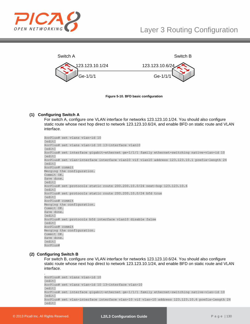
© 2012 Pica8 Inc. All © 2012 Pica8 Inc. All
Layer 3 Routing Configuration
© 2013 Pica8 Inc. All Rights Reserved. L2/L3 Configuration Guide
P a g e | 130
Switch A
Ge-1/1/1
123.123.10.6/24
Switch B
123.123.10.1/24
Ge-1/1/1
Figure 5-10. BFD basic configuration
(1) Configuring Switch A For switch A, configure one VLAN interface for networks 123.123.10.1/24. You should also configure static route whose next hop direct to network 123.123.10.6/24, and enable BFD on static route and VLAN interface. XorPlus# set vlans vlan-id 10
[edit]
XorPlus# set vlans vlan-id 10 l3-interface vlan10
[edit]
XorPlus# set interface gigabit-ethernet ge-1/1/1 family ethernet-switching native-vlan-id 10
[edit]
XorPlus# set vlan-interface interface vlan10 vif vlan10 address 123.123.10.1 prefix-length 24
[edit]
XorPlus# commit
Merging the configuration.
Commit OK.
Save done.
[edit]
XorPlus# set protocols static route 200.200.10.0/24 next-hop 123.123.10.6
[edit]
XorPlus# set protocols static route 200.200.10.0/24 bfd true
[edit]
XorPlus# commit
Merging the configuration.
Commit OK.
Save done.
[edit]
XorPlus# set protocols bfd interface vlan10 disable false
[edit]
XorPlus# commit
Merging the configuration.
Commit OK.
Save done.
[edit]
XorPlus#
(2) Configuring Switch B For switch B, configure one VLAN interface for networks 123.123.10.6/24. You should also configure static route whose next hop direct to network 123.123.10.1/24, and enable BFD on static route and VLAN interface. . XorPlus# set vlans vlan-id 10
[edit]
XorPlus# set vlans vlan-id 10 l3-interface vlan-10
[edit]
XorPlus# set interface gigabit-ethernet ge-1/1/1 family ethernet-switching native-vlan-id 10
[edit]
XorPlus# set vlan-interface interface vlan-10 vif vlan-10 address 123.123.10.6 prefix-length 24
[edit]

© 2012 Pica8 Inc. All © 2012 Pica8 Inc. All
Layer 3 Routing Configuration
© 2013 Pica8 Inc. All Rights Reserved. L2/L3 Configuration Guide
P a g e | 131
XorPlus# commit
Merging the configuration.
Commit OK.
Save done.
[edit]
XorPlus# set protocols static route 178.178.10.0/24 next-hop 123.123.10.1
[edit]
XorPlus# set protocols static route 178.178.10.0/24 bfd true
[edit]
XorPlus# commit
Merging the configuration.
Commit OK.
Save done.
[edit]
XorPlus# set protocols bfd interface vlan-10 disable false
[edit]
XorPlus# commit
Merging the configuration.
Commit OK.
Save done.
[edit]
XorPlus#
(3) Verifying the BFD configuration You can verify the BFD configuration of a switch by checking its BFD neighbor.
XorPlus# run show bfd neighbor ipv4
Detect Transmit
Local Address Remote Address Interface State Time(ms) Interval(ms) Multiplier
--------------- --------------- --------- --------- -------- ------------ ----------
123.123.10.1 123.123.10.6 vlan10 Up 1500 500 3
XorPlus#
BGP Configuration Guide (1) Configuring a BGP router ID
The router ID should be configured first when you configure BGP. The router ID is a string similar to the IP address, and is the identifier of a BGP router in an AS. You should not change the router IDafter completing the configuration. By default, the BGP router ID is not configured. XorPlus# set protocols bgp bgp-id 1.1.1.1
[edit]
XorPlus# commit
Waiting for merging configuration.
Commit OK.
Save done.
[edit]
XorPlus#
(2) Configuring BGP localAS The localAS (autonomous system) should be configured first when you configure BGP. The AS_Path attribute records all the AS’s that a route passes through from the source to the destination,following the order of vectors.
XorPlus# set protocols bgp local-as 100
[edit]
XorPlus# commit
Waiting for merging configuration.

© 2012 Pica8 Inc. All © 2012 Pica8 Inc. All
Layer 3 Routing Configuration
© 2013 Pica8 Inc. All Rights Reserved. L2/L3 Configuration Guide
P a g e | 132
Commit OK.
Save done.
[edit]
XorPlus#
(3) Configuring external BGP peering If the AS number of the specified peer is different from the local AS number during the configuration of BGP peers, an EBGP peer is configured. To establish point-to-point connections between peer autonomous systems, configure a BGP session on each interface of a point-to-point link. Generally,such sessions are made at network exit points with neighboring hosts outside the AS. XorPlus# set protocols bgp local-as 100
[edit]
XorPlus# set protocols bgp peer 192.168.49.1 as 200
[edit]
XorPlus# set protocols bgp peer 192.168.49.1 next-hop-self true[edit]
XorPlus# set protocols bgp peer 192.168.49.1 local-ip 192.168.49.2
[edit]
XorPlus# commit
Waiting for merging configuration.
Commit OK.
Save done.
[edit]
XorPlus#
(4) Configuring internal BGP peering If the AS number of the specified peer is the same as the local AS number during the configuration of BGP peers, an IBGP peer is configured. XorPlus# set protocols bgp local-as 100
[edit]
XorPlus# set protocols bgp peer 192.168.49.1 as 100
[edit]
XorPlus# set protocols bgp peer 192.168.49.1 next-hop-self true[edit]
XorPlus# set protocols bgp peer 192.168.49.1 local-ip 192.168.49.2
[edit]
XorPlus# commit
Waiting for merging configuration.
Commit OK.
Save done.
[edit]
XorPlus#
(5) Configuring the BGP Local Preference Internal BGP (IBGP) sessions use a metric called the local preference, which is carried in IBGP update packets in the path attribute LOCAL_PREF.When an autonomous system (AS) has multiple routes to another AS, the local preference indicates the degree of preference for one route over the other routes. Expectedly, theroute with the highest local preference value is preferred. XorPlus# set policy policy-statement send-network term t1 from network4 172.168.200.0/24
[edit]
XorPlus# set policy policy-statement send-network term t1 from protocol bgp
[edit]
XorPlus# set policy policy-statement send-network term t1 then localpref 200
[edit]
XorPlus# commit
Waiting for merging configuration.
Commit OK.
Save done.
[edit]

© 2012 Pica8 Inc. All © 2012 Pica8 Inc. All
Layer 3 Routing Configuration
© 2013 Pica8 Inc. All Rights Reserved. L2/L3 Configuration Guide
P a g e | 133
XorPlus# set protocols bgp peer 192.168.49.1 export send-network
[edit]
XorPlus# commit
Waiting for merging configuration.
Commit OK.
Save done.
[edit]
XorPlus#
(6) Configuring BGP MED The multi-exit discriminator (MED) helps determine the optimal route for the incoming traffic of an AS, and is similar to the metric used in IGP. When a BGP device obtains multiple routes to the same destination address but with different nexthops from EBGP peers, the BGP device selects the route with the smallest MED value as the optimal route. XorPlus# set policy policy-statement send-network term t1 from network4 172.168.200.0/24
[edit]
XorPlus# set policy policy-statement send-network term t1 from protocol bgp
[edit]
XorPlus# set policy policy-statement send-network term t1 then med 200
[edit]
XorPlus# commit
Waiting for merging configuration.
Commit OK.
Save done.
[edit]
XorPlus# set protocols bgp peer 192.168.49.1 export send-network
[edit]
XorPlus# commit
Waiting for merging configuration.
Commit OK.
Save done.
[edit]
XorPlus#
(7) Configuring BGP nexthop ● When an Autonomous System Boundary Router (ASBR) forwards the route learned from an EBGP
peer to an IBGP peer, the ASBR, by default, does not change the next hop of the route.When the IBGP peer receives this route, it finds the nexthop unreachable, sets the route to inactive, and does not use this route to guide traffic forwarding.
● To enable the IBGP peer to use this route to guide traffic forwarding, configure the ASBR to set its IP
address as the next hop of the route when the ASBR forwards this route to the IBGP peer. After the IBGP peer receives this route from the ASBR, it finds the next hop of the route reachable, sets the route to active,and uses this route to guide traffic forwarding.
● When a BGP route changes, BGP needs to iterate the indirect next hop of the route again. If no
restriction is imposed on the iterated route, BGP may iterate the next hop to an incorrect forwarding path, causing traffic loss. Configure routing policy-based route iteration to prevent traffic loss.
XorPlus# set protocols bgp local-as 100
[edit]
XorPlus# set protocols bgp peer 192.168.49.1 as 100
[edit]
XorPlus# set protocols bgp peer 192.168.49.1 next-hop-self true[edit]
XorPlus# set protocols bgp peer 192.168.49.1 local-ip 192.168.49.2
[edit]
XorPlus# commit
Waiting for merging configuration.
Commit OK.
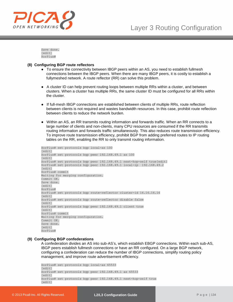
© 2012 Pica8 Inc. All © 2012 Pica8 Inc. All
Layer 3 Routing Configuration
© 2013 Pica8 Inc. All Rights Reserved. L2/L3 Configuration Guide
P a g e | 134
Save done.
[edit]
XorPlus#
(8) Configuring BGP route reflectors ● To ensure the connectivity between IBGP peers within an AS, you need to establish fullmesh
connections between the IBGP peers. When there are many IBGP peers, it is costly to establish a fullymeshed network. A route reflector (RR) can solve this problem.
● A cluster ID can help prevent routing loops between multiple RRs within a cluster, and between
clusters. When a cluster has multiple RRs, the same cluster ID must be configured for all RRs within the cluster.
● If full-mesh IBGP connections are established between clients of multiple RRs, route reflection
between clients is not required and wastes bandwidth resources. In this case, prohibit route reflection between clients to reduce the network burden.
● Within an AS, an RR transmits routing information and forwards traffic. When an RR connects to a
large number of clients and non-clients, many CPU resources are consumed if the RR transmits routing information and forwards traffic simultaneously. This also reduces route transmission efficiency. To improve route transmission efficiency, prohibit BGP from adding preferred routes to IP routing tables on the RR, enabling the RR to only transmit routing information.
XorPlus# set protocols bgp local-as 100
[edit]
XorPlus# set protocols bgp peer 192.168.49.1 as 100
[edit]
XorPlus# set protocols bgp peer 192.168.49.1 next-hop-self true[edit]
XorPlus# set protocols bgp peer 192.168.49.1 local-ip 192.168.49.2
[edit]
XorPlus# commit
Waiting for merging configuration.
Commit OK.
Save done.
[edit]
XorPlus#
XorPlus# set protocols bgp route-reflector cluster-id 16.16.16.16
[edit]
XorPlus# set protocols bgp route-reflector disable false
[edit]
XorPlus# set protocols bgp peer 192.168.49.1 client true
[edit]
XorPlus# commit
Waiting for merging configuration.
Commit OK.
Save done.
[edit]
XorPlus#
(9) Configuring BGP confederations A confederation divides an AS into sub-AS’s, which establish EBGP connections. Within each sub-AS, IBGP peers establish fullmesh connections or have an RR configured. On a large BGP network, configuring a confederation can reduce the number of IBGP connections, simplify routing policy management, and improve route advertisement efficiency.
XorPlus# set protocols bgp local-as 65533
[edit]
XorPlus# set protocols bgp peer 192.168.49.1 as 65533
[edit]
XorPlus# set protocols bgp peer 192.168.49.1 next-hop-self true
[edit]

© 2012 Pica8 Inc. All © 2012 Pica8 Inc. All
Layer 3 Routing Configuration
© 2013 Pica8 Inc. All Rights Reserved. L2/L3 Configuration Guide
P a g e | 135
XorPlus# set protocols bgp peer 192.168.49.1 local-ip 192.168.49.2
[edit]
XorPlus# commit
Waiting for merging configuration.
Commit OK.
Save done.
[edit]
XorPlus#
XorPlus# set protocols bgp confederation identifier 2000
[edit]
XorPlus# set protocols bgp confederation disable false
[edit]
XorPlus# set protocols bgp peer 192.168.49.1 confederation-member true
[edit]
XorPlus# commit
Waiting for merging configuration.
Commit OK.
Save done.
[edit]
XorPlus#
(10) Configuring the BGP connect timer Hold timers can be configured for all peers. The proper maximum interval at which Keepalive messages are sent is one third the holdtime. XorPlus# set protocols bgp peer 192.168.49.1 holdtime 30
XorPlus# commit
Waiting for merging configuration.
Commit OK.
Save done.
[edit]
XorPlus#
(11) Configuring MD5 authentication for TCP connections Configure Message Digest5 (MD5) authentication on a TCP connection between two BGP peers. The two peers must have the same configured password to establish TCP connections. XorPlus# set protocols bgp peer 192.168.11.10 md5-password pica8
XorPlus# commit
Waiting for merging configuration.
Commit OK.
Save done.
[edit]
XorPlus#
(12) Configuring EBGPfast-external-fallover
This feature allows BGP to immediately respond to a fault on an interface, and delete the direct EBGP sessions on the interface without waiting for the hold timer to expire. It implements rapid BGP network convergence. By default, EBGP fast-external-fallover is disabled. XorPlus# set protocols bgp fast-external-fallover disable false
XorPlus# commit
Waiting for merging configuration.
Commit OK.
Save done.
[edit]
XorPlus#
(13) Configuring BGP route summarization
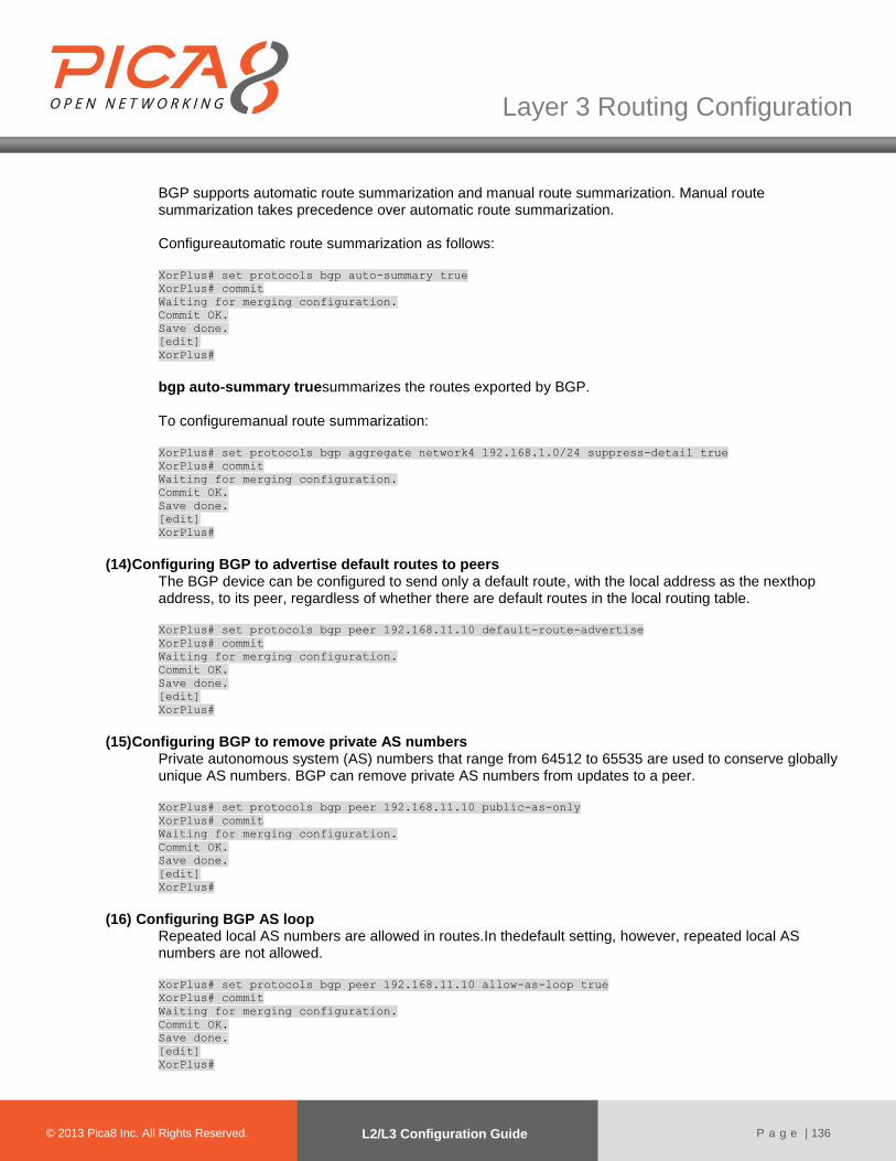
© 2012 Pica8 Inc. All © 2012 Pica8 Inc. All
Layer 3 Routing Configuration
© 2013 Pica8 Inc. All Rights Reserved. L2/L3 Configuration Guide
P a g e | 136
BGP supports automatic route summarization and manual route summarization. Manual route summarization takes precedence over automatic route summarization.
Configureautomatic route summarization as follows: XorPlus# set protocols bgp auto-summary true
XorPlus# commit
Waiting for merging configuration.
Commit OK.
Save done.
[edit]
XorPlus#
bgp auto-summary truesummarizes the routes exported by BGP. To configuremanual route summarization: XorPlus# set protocols bgp aggregate network4 192.168.1.0/24 suppress-detail true
XorPlus# commit
Waiting for merging configuration.
Commit OK.
Save done.
[edit]
XorPlus#
(14) Configuring BGP to advertise default routes to peers
The BGP device can be configured to send only a default route, with the local address as the nexthop address, to its peer, regardless of whether there are default routes in the local routing table. XorPlus# set protocols bgp peer 192.168.11.10 default-route-advertise
XorPlus# commit
Waiting for merging configuration.
Commit OK.
Save done.
[edit]
XorPlus#
(15) Configuring BGP to remove private AS numbers
Private autonomous system (AS) numbers that range from 64512 to 65535 are used to conserve globally unique AS numbers. BGP can remove private AS numbers from updates to a peer.
XorPlus# set protocols bgp peer 192.168.11.10 public-as-only
XorPlus# commit
Waiting for merging configuration.
Commit OK.
Save done.
[edit]
XorPlus#
(16) Configuring BGP AS loop
Repeated local AS numbers are allowed in routes.In thedefault setting, however, repeated local AS numbers are not allowed. XorPlus# set protocols bgp peer 192.168.11.10 allow-as-loop true
XorPlus# commit
Waiting for merging configuration.
Commit OK.
Save done.
[edit]
XorPlus#

© 2012 Pica8 Inc. All © 2012 Pica8 Inc. All
Layer 3 Routing Configuration
© 2013 Pica8 Inc. All Rights Reserved. L2/L3 Configuration Guide
P a g e | 137
(17) Configuring BGP load balancing If multiple paths to a destination exist, you can configure load balancing over such paths to improve linkutilization. Enable BGP load balancing: XorPlus# set protocols bgp multipath disable false
XorPlus# commit
Waiting for merging configuration.
Commit OK.
Save done.
[edit]
XorPlus#
BGP will not load balance across multiple paths by default. This is acceptable if youare multihomed to a single AS, but what if you are multihomed to different AS path? In that case,you cannot load balance across theoretically equal paths. Enter the BGP multipath path-relaxcommand: XorPlus# set protocols bgp multipath path-relax true
XorPlus# commit
Waiting for merging configuration.
Commit OK.
Save done.
[edit]
XorPlus#
BGP Basic Configuration Example
●As shown in Fig. 5-9, BGP runs between switches.An EBGP connection is established between SwitchA and SwitchB, and IBGP fullmesh connections are established betweenSwitchB, SwitchC, and SwitchD.
●Configure IBGP connections between SwitchB, SwitchC, and SwitchD.
●Configure an EBGP connection between SwitchA and SwitchB.
SwitchA SwitchB
SwitchC
SwitchD
Ge-1/1/1 Vlan10192.168.10.1/24
Ge-1/1/2 Vlan20192.168.20.1/24
Ge-1/1/2 Vlan20192.168.20.2/24
Ge-1/1/3 Vlan30192.168.30.1/24
Ge-1/1/4 Vlan40192.168.40.1/24
Ge-1/1/4 Vlan40192.168.40.2/24
Ge-1/1/3 Vlan30192.168.30.2/24
Ge-1/1/5 Vlan50192.168.50.1/24
Ge-1/1/5 Vlan50192.168.50.2/24
Figure 5-9. BGP configuration.
(7) Configuring SwitchA Configure the VLAN that each interface belongs to.
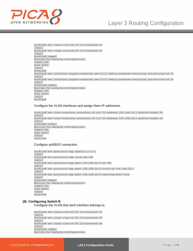
© 2012 Pica8 Inc. All © 2012 Pica8 Inc. All
Layer 3 Routing Configuration
© 2013 Pica8 Inc. All Rights Reserved. L2/L3 Configuration Guide
P a g e | 138
XorPlus# set vlans vlan-id 10 l3-interface 10
[edit]
XorPlus# set vlans vlan-id 20 l3-interface 20
[edit]
XorPlus# commit
Waiting for merging configuration.
Commit OK.
Save done.
[edit]
XorPlus#
XorPlus# set interface gigabit-ethernet ge-1/1/1 family ethernet-switching native-vlan-id 10
[edit]
XorPlus# set interface gigabit-ethernet ge-1/1/2 family ethernet-switching native-vlan-id 20
[edit]
XorPlus# commit
Waiting for merging configuration.
Commit OK.
Save done.
[edit]
XorPlus#
Configure the VLAN interfaces and assign them IP addresses. XorPlus# set vlan-interface interface 10 vif 10 address 192.168.10.1 prefix-length 24
[edit]
XorPlus# set vlan-interface interface 20 vif 20 address 192.168.20.1 prefix-length 24
[edit]
XorPlus# commit
Waiting for merging configuration.
Commit OK.
Save done.
[edit]
XorPlus#
Configure anEBGP connection. XorPlus# set protocols bgp bgp-id 1.1.1.1
[edit]
XorPlus# set protocols bgp local-as 100
[edit]
XorPlus# set protocols bgp peer 192.168.20.2 as 200
[edit]
XorPlus# set protocols bgp peer 192.168.20.2 local-ip 192.168.20.1
[edit]
XorPlus# set protocols bgp peer 192.168.20.2 next-hop-self true
[edit]
XorPlus# commit
Waiting for merging configuration.
Commit OK.
Save done.
[edit]
XorPlus#
(8) Configuring Switch B Configure the VLAN that each interface belongs to.
XorPlus# set vlans vlan-id 20 l3-interface 20
[edit]
XorPlus# set vlans vlan-id 30 l3-interface 30
[edit]
XorPlus# set vlans vlan-id 40 l3-interface 40
[edit]
XorPlus# commit
Waiting for merging configuration.

© 2012 Pica8 Inc. All © 2012 Pica8 Inc. All
Layer 3 Routing Configuration
© 2013 Pica8 Inc. All Rights Reserved. L2/L3 Configuration Guide
P a g e | 139
Commit OK.
Save done.
[edit]
XorPlus#
XorPlus# set interface gigabit-ethernet ge-1/1/2 family ethernet-switching native-vlan-id 20
[edit]
XorPlus# set interface gigabit-ethernet ge-1/1/3 family ethernet-switching native-vlan-id 30
[edit]
XorPlus# set interface gigabit-ethernet ge-1/1/4 family ethernet-switching native-vlan-id 40
[edit]
XorPlus# commit
Waiting for merging configuration.
Commit OK.
Save done.
[edit]
XorPlus#
Configure the VLAN interfaces and assign them IP addresses.
XorPlus# set vlan-interface interface 20 vif 20 address 192.168.20.2 prefix-length 24
[edit]
XorPlus# set vlan-interface interface 30 vif 30 address 192.168.30.1 prefix-length 24
[edit]
XorPlus# set vlan-interface interface 40 vif 40 address 192.168.40.1 prefix-length 24
[edit]
XorPlus# commit
Waiting for merging configuration.
Commit OK.
Save done.
[edit]
XorPlus#
Configure EBGP and IBGP connections.
XorPlus# set protocols bgp bgp-id 2.2.2.2
[edit]
XorPlus# set protocols bgp local-as 200
[edit]
XorPlus# set protocols bgp peer 192.168.20.1 as 100
[edit]
XorPlus# set protocols bgp peer 192.168.20.1 local-ip 192.168.20.2
[edit]
XorPlus# set protocols bgp peer 192.168.20.1 next-hop-self true
[edit]
XorPlus# set protocols bgp peer 192.168.30.2 as 200
[edit]
XorPlus# set protocols bgp peer 192.168.30.2 local-ip 192.168.30.1
[edit]
XorPlus# set protocols bgp peer 192.168.30.2 next-hop-self true
[edit]
XorPlus# set protocols bgp peer 192.168.40.2 as 200
[edit]
XorPlus# set protocols bgp peer 192.168.40.2 local-ip 192.168.40.1
[edit]
XorPlus# set protocols bgp peer 192.168.40.2 next-hop-self true
[edit]
XorPlus# commit
Waiting for merging configuration.
Commit OK.
Save done.
[edit]
XorPlus#
(9) Configuring Switch C Configure the VLAN that each interface belongs to.
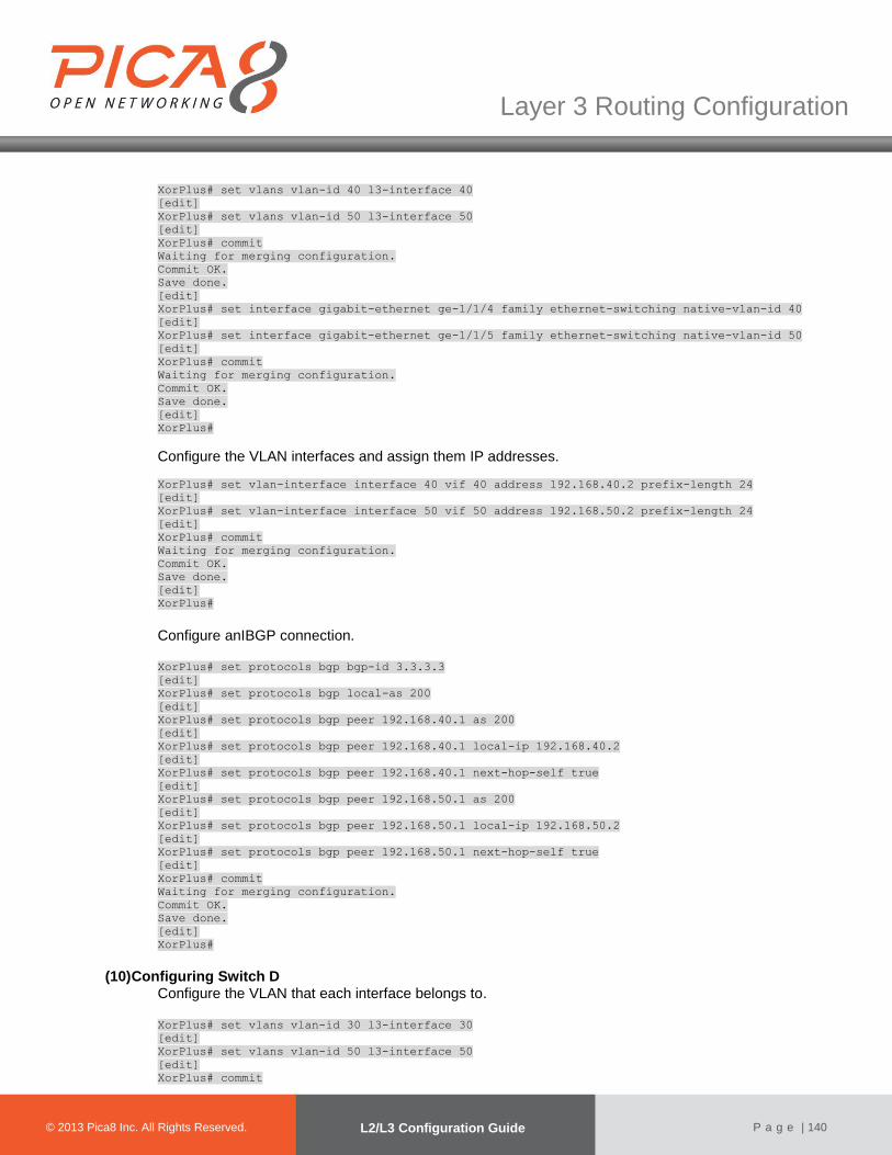
© 2012 Pica8 Inc. All © 2012 Pica8 Inc. All
Layer 3 Routing Configuration
© 2013 Pica8 Inc. All Rights Reserved. L2/L3 Configuration Guide
P a g e | 140
XorPlus# set vlans vlan-id 40 l3-interface 40
[edit]
XorPlus# set vlans vlan-id 50 l3-interface 50
[edit]
XorPlus# commit
Waiting for merging configuration.
Commit OK.
Save done.
[edit]
XorPlus# set interface gigabit-ethernet ge-1/1/4 family ethernet-switching native-vlan-id 40
[edit]
XorPlus# set interface gigabit-ethernet ge-1/1/5 family ethernet-switching native-vlan-id 50
[edit]
XorPlus# commit
Waiting for merging configuration.
Commit OK.
Save done.
[edit]
XorPlus#
Configure the VLAN interfaces and assign them IP addresses.
XorPlus# set vlan-interface interface 40 vif 40 address 192.168.40.2 prefix-length 24
[edit]
XorPlus# set vlan-interface interface 50 vif 50 address 192.168.50.2 prefix-length 24
[edit]
XorPlus# commit
Waiting for merging configuration.
Commit OK.
Save done.
[edit]
XorPlus#
Configure anIBGP connection.
XorPlus# set protocols bgp bgp-id 3.3.3.3
[edit]
XorPlus# set protocols bgp local-as 200
[edit]
XorPlus# set protocols bgp peer 192.168.40.1 as 200
[edit]
XorPlus# set protocols bgp peer 192.168.40.1 local-ip 192.168.40.2
[edit]
XorPlus# set protocols bgp peer 192.168.40.1 next-hop-self true
[edit]
XorPlus# set protocols bgp peer 192.168.50.1 as 200
[edit]
XorPlus# set protocols bgp peer 192.168.50.1 local-ip 192.168.50.2
[edit]
XorPlus# set protocols bgp peer 192.168.50.1 next-hop-self true
[edit]
XorPlus# commit
Waiting for merging configuration.
Commit OK.
Save done.
[edit]
XorPlus#
(10) Configuring Switch D Configure the VLAN that each interface belongs to.
XorPlus# set vlans vlan-id 30 l3-interface 30
[edit]
XorPlus# set vlans vlan-id 50 l3-interface 50
[edit]
XorPlus# commit
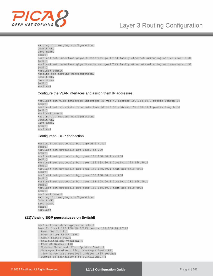
© 2012 Pica8 Inc. All © 2012 Pica8 Inc. All
Layer 3 Routing Configuration
© 2013 Pica8 Inc. All Rights Reserved. L2/L3 Configuration Guide
P a g e | 141
Waiting for merging configuration.
Commit OK.
Save done.
[edit]
XorPlus# set interface gigabit-ethernet ge-1/1/3 family ethernet-switching native-vlan-id 30
[edit]
XorPlus# set interface gigabit-ethernet ge-1/1/5 family ethernet-switching native-vlan-id 50
[edit]
XorPlus# commit
Waiting for merging configuration.
Commit OK.
Save done.
[edit]
XorPlus#
Configure the VLAN interfaces and assign them IP addresses. XorPlus# set vlan-interface interface 30 vif 40 address 192.168.30.2 prefix-length 24
[edit]
XorPlus# set vlan-interface interface 50 vif 50 address 192.168.50.1 prefix-length 24
[edit]
XorPlus# commit
Waiting for merging configuration.
Commit OK.
Save done.
[edit]
XorPlus#
Configurean IBGP connection. XorPlus# set protocols bgp bgp-id 4.4.4.4
[edit]
XorPlus# set protocols bgp local-as 200
[edit]
XorPlus# set protocols bgp peer 192.168.30.1 as 200
[edit]
XorPlus# set protocols bgp peer 192.168.30.1 local-ip 192.168.30.2
[edit]
XorPlus# set protocols bgp peer 192.168.30.1 next-hop-self true
[edit]
XorPlus# set protocols bgp peer 192.168.50.2 as 200
[edit]
XorPlus# set protocols bgp peer 192.168.50.2 local-ip 192.168.50.1
[edit]
XorPlus# set protocols bgp peer 192.168.50.2 next-hop-self true
[edit]
XorPlus# commit
Waiting for merging configuration.
Commit OK.
Save done.
[edit]
XorPlus#
(11) Viewing BGP peerstatuses on SwitchB
XorPlus# run show bgp peers detail
Peer 2: local 192.168.10.2/179 remote 192.168.10.1/179
Peer ID: 1.1.1.1
Peer State: ESTABLISHED
Admin State: START
Negotiated BGP Version: 4
Peer AS Number: 100
Updates Received: 20, Updates Sent: 2
Messages Received: 634, Messages Sent: 611
Time since last received update: 1685 seconds
Number of transitions to ESTABLISHED: 1

© 2012 Pica8 Inc. All © 2012 Pica8 Inc. All
Layer 3 Routing Configuration
© 2013 Pica8 Inc. All Rights Reserved. L2/L3 Configuration Guide
P a g e | 142
Time since last entering ESTABLISHED state: 15995 seconds
Retry Interval: 120 seconds
Hold Time: 90 seconds, Keep Alive Time: 30 seconds
Configured Hold Time: 90 seconds, Configured Keep Alive Time: 30 seconds
Minimum AS Origination Interval: 0 seconds
Minimum Route Advertisement Interval: 0 seconds
Peer 2: local 192.168.30.1/179 remote 192.168.30.2/179
Peer ID: 4.4.4.4
Peer State: ESTABLISHED
Admin State: START
Negotiated BGP Version: 4
Peer AS Number: 100
Updates Received: 20, Updates Sent: 2
Messages Received: 634, Messages Sent: 611
Time since last received update: 1685 seconds
Number of transitions to ESTABLISHED: 1
Time since last entering ESTABLISHED state: 15995 seconds
Retry Interval: 120 seconds
Hold Time: 90 seconds, Keep Alive Time: 30 seconds
Configured Hold Time: 90 seconds, Configured Keep Alive Time: 30 seconds
Minimum AS Origination Interval: 0 seconds
Minimum Route Advertisement Interval: 0 seconds
Peer 3: local 192.168.40.1/179 remote 192.168.40.2/179
Peer ID: 3.3.3.3
Peer State: ESTABLISHED
Admin State: START
Negotiated BGP Version: 4
Peer AS Number: 100
Updates Received: 20, Updates Sent: 2
Messages Received: 634, Messages Sent: 611
Time since last received update: 1685 seconds
Number of transitions to ESTABLISHED: 1
Time since last entering ESTABLISHED state: 15995 seconds
Retry Interval: 120 seconds
Hold Time: 90 seconds, Keep Alive Time: 30 seconds
Configured Hold Time: 90 seconds, Configured Keep Alive Time: 30 seconds
Minimum AS Origination Interval: 0 seconds
Minimum Route Advertisement Interval: 0 seconds
XorPlus#
(12) Configuring Switch A to advertise route 192.168.10.0/24
XorPlus# set policy policy-statement direct-to-bgp term t1 from protocol connected
[edit]
XorPlus# set policy policy-statement direct-to-bgp term t1 from network4 192.168.10.0/24
[edit]
XorPlus# set policy policy-statement direct-to-bgp term t1 then accept
[edit]
XorPlus# commit
Waiting for merging configuration.
Commit OK.
Save done.
[edit]
XorPlus#
XorPlus# set protocols bgp export direct-to-bgp
[edit]
XorPlus# commit
Waiting for merging configuration.
Commit OK.
Save done.
[edit]
XorPlus#
View the BGP routing table of Switch B:
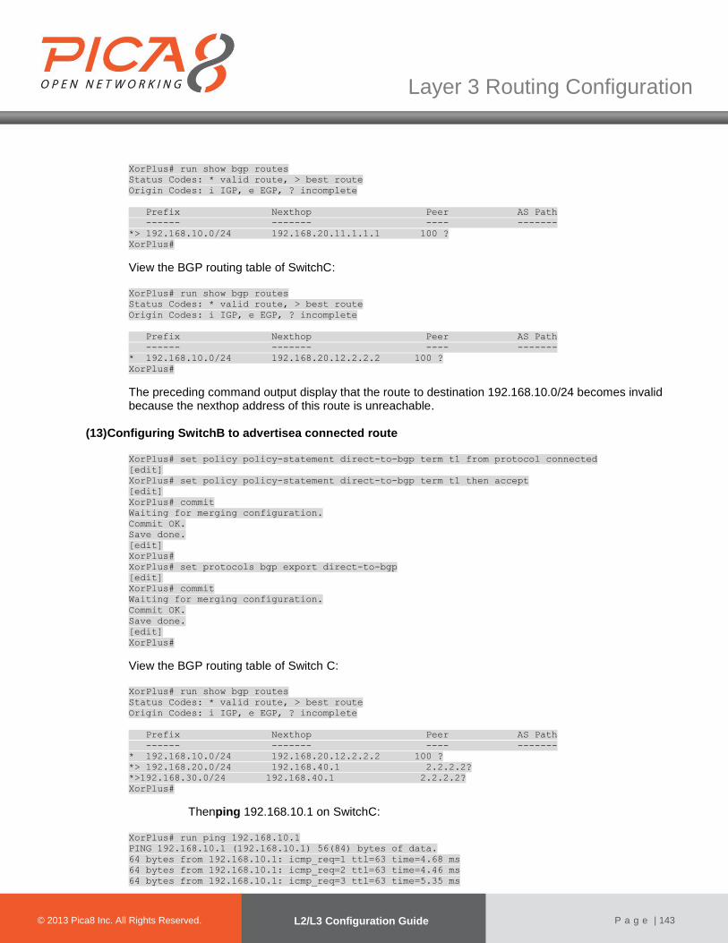
© 2012 Pica8 Inc. All © 2012 Pica8 Inc. All
Layer 3 Routing Configuration
© 2013 Pica8 Inc. All Rights Reserved. L2/L3 Configuration Guide
P a g e | 143
XorPlus# run show bgp routes
Status Codes: * valid route, > best route
Origin Codes: i IGP, e EGP, ? incomplete
Prefix Nexthop Peer AS Path
------ ------- ---- -------
*> 192.168.10.0/24 192.168.20.11.1.1.1 100 ?
XorPlus#
View the BGP routing table of SwitchC: XorPlus# run show bgp routes
Status Codes: * valid route, > best route
Origin Codes: i IGP, e EGP, ? incomplete
Prefix Nexthop Peer AS Path
------ ------- ---- -------
* 192.168.10.0/24 192.168.20.12.2.2.2 100 ?
XorPlus#
The preceding command output display that the route to destination 192.168.10.0/24 becomes invalid because the nexthop address of this route is unreachable.
(13) Configuring SwitchB to advertisea connected route
XorPlus# set policy policy-statement direct-to-bgp term t1 from protocol connected
[edit]
XorPlus# set policy policy-statement direct-to-bgp term t1 then accept
[edit]
XorPlus# commit
Waiting for merging configuration.
Commit OK.
Save done.
[edit]
XorPlus#
XorPlus# set protocols bgp export direct-to-bgp
[edit]
XorPlus# commit
Waiting for merging configuration.
Commit OK.
Save done.
[edit]
XorPlus#
View the BGP routing table of Switch C: XorPlus# run show bgp routes
Status Codes: * valid route, > best route
Origin Codes: i IGP, e EGP, ? incomplete
Prefix Nexthop Peer AS Path
------ ------- ---- -------
* 192.168.10.0/24 192.168.20.12.2.2.2 100 ?
*> 192.168.20.0/24 192.168.40.1 2.2.2.2?
*>192.168.30.0/24 192.168.40.1 2.2.2.2?
XorPlus#
Thenping 192.168.10.1 on SwitchC: XorPlus# run ping 192.168.10.1
PING 192.168.10.1 (192.168.10.1) 56(84) bytes of data.
64 bytes from 192.168.10.1: icmp_req=1 ttl=63 time=4.68 ms
64 bytes from 192.168.10.1: icmp_req=2 ttl=63 time=4.46 ms
64 bytes from 192.168.10.1: icmp_req=3 ttl=63 time=5.35 ms
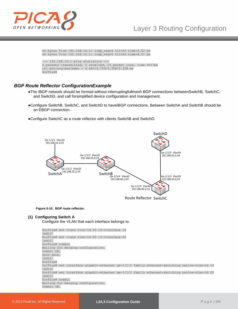
© 2012 Pica8 Inc. All © 2012 Pica8 Inc. All
Layer 3 Routing Configuration
© 2013 Pica8 Inc. All Rights Reserved. L2/L3 Configuration Guide
P a g e | 144
64 bytes from 192.168.10.1: icmp_req=4 ttl=63 time=4.52 ms
64 bytes from 192.168.10.1: icmp_req=5 ttl=63 time=4.51 ms
--- 192.168.10.1 ping statistics ---
5 packets transmitted, 5 received, 0% packet loss, time 4017ms
rtt min/avg/max/mdev = 4.460/4.709/5.358/0.338 ms
XorPlus#
BGP Route Reflector ConfigurationExample
●The IBGP network should be formed without interruptingfullmesh BGP connections betweenSwitchB, SwitchC, and SwitchD, and call forsimplified device configuration and management.
●Configure SwitchB, SwitchC, and SwitchD to haveIBGP connections. Between SwitchA and SwitchB should be an EBGP connection.
●Configure SwitchC as a route reflector with clients SwitchB and SwitchD.
SwitchA SwitchB
SwitchC
SwitchD
Ge-1/1/1 Vlan10192.168.10.1/24
Ge-1/1/2 Vlan20192.168.20.1/24
Ge-1/1/2 Vlan20192.168.20.2/24
Ge-1/1/4 Vlan40192.168.40.1/24
Ge-1/1/4 Vlan40192.168.40.2/24
Ge-1/1/5 Vlan50192.168.50.1/24
Ge-1/1/5 Vlan50192.168.50.2/24
Route Reflector
Figure 5-10. BGP route reflector.
(1) Configuring Switch A Configure the VLAN that each interface belongs to.
XorPlus# set vlans vlan-id 10 l3-interface 10
[edit]
XorPlus# set vlans vlan-id 20 l3-interface 20
[edit]
XorPlus# commit
Waiting for merging configuration.
Commit OK.
Save done.
[edit]
XorPlus#
XorPlus# set interface gigabit-ethernet ge-1/1/1 family ethernet-switching native-vlan-id 10
[edit]
XorPlus# set interface gigabit-ethernet ge-1/1/2 family ethernet-switching native-vlan-id 20
[edit]
XorPlus# commit
Waiting for merging configuration.
Commit OK.
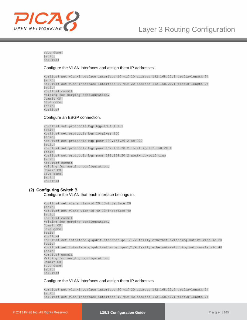
© 2012 Pica8 Inc. All © 2012 Pica8 Inc. All
Layer 3 Routing Configuration
© 2013 Pica8 Inc. All Rights Reserved. L2/L3 Configuration Guide
P a g e | 145
Save done.
[edit]
XorPlus#
Configure the VLAN interfaces and assign them IP addresses. XorPlus# set vlan-interface interface 10 vif 10 address 192.168.10.1 prefix-length 24
[edit]
XorPlus# set vlan-interface interface 20 vif 20 address 192.168.20.1 prefix-length 24
[edit]
XorPlus# commit
Waiting for merging configuration.
Commit OK.
Save done.
[edit]
XorPlus#
Configure an EBGP connection. XorPlus# set protocols bgp bgp-id 1.1.1.1
[edit]
XorPlus# set protocols bgp local-as 100
[edit]
XorPlus# set protocols bgp peer 192.168.20.2 as 200
[edit]
XorPlus# set protocols bgp peer 192.168.20.2 local-ip 192.168.20.1
[edit]
XorPlus# set protocols bgp peer 192.168.20.2 next-hop-self true
[edit]
XorPlus# commit
Waiting for merging configuration.
Commit OK.
Save done.
[edit]
XorPlus#
(2) Configuring Switch B Configure the VLAN that each interface belongs to. XorPlus# set vlans vlan-id 20 l3-interface 20
[edit]
XorPlus# set vlans vlan-id 40 l3-interface 40
[edit]
XorPlus# commit
Waiting for merging configuration.
Commit OK.
Save done.
[edit]
XorPlus#
XorPlus# set interface gigabit-ethernet ge-1/1/2 family ethernet-switching native-vlan-id 20
[edit]
XorPlus# set interface gigabit-ethernet ge-1/1/4 family ethernet-switching native-vlan-id 40
[edit]
XorPlus# commit
Waiting for merging configuration.
Commit OK.
Save done.
[edit]
XorPlus#
Configure the VLAN interfaces and assign them IP addresses. XorPlus# set vlan-interface interface 20 vif 20 address 192.168.20.2 prefix-length 24
[edit]
XorPlus# set vlan-interface interface 40 vif 40 address 192.168.40.1 prefix-length 24

© 2012 Pica8 Inc. All © 2012 Pica8 Inc. All
Layer 3 Routing Configuration
© 2013 Pica8 Inc. All Rights Reserved. L2/L3 Configuration Guide
P a g e | 146
[edit]
XorPlus# commit
Waiting for merging configuration.
Commit OK.
Save done.
[edit]
XorPlus#
Configure EBGP and IBGP connections.
XorPlus# set policy policy-statement p2 term t1 from protocol bgp
[edit]
XorPlus#
XorPlus# set policy policy-statement p2 term t1 from network4 192.168.10.0/24
[edit]
XorPlus# set policy policy-statement p2 term t1 then nexthop4 192.168.40.1
[edit]
XorPlus# commit
Waiting for merging configuration.
Commit OK.
Save done.
[edit]
XorPlus#
XorPlus# set protocols bgp bgp-id 2.2.2.2
[edit]
XorPlus# set protocols bgp local-as 200
[edit]
XorPlus# set protocols bgp peer 192.168.20.2 as 100
[edit]
XorPlus# set protocols bgp peer 192.168.20.1 local-ip 192.168.20.2
[edit]
XorPlus# set protocols bgp peer 192.168.20.1 next-hop-self true
[edit]
XorPlus# set protocols bgp peer 192.168.40.2 as 200
[edit]
XorPlus# set protocols bgp peer 192.168.40.2 local-ip 192.168.40.1
[edit]
XorPlus# set protocols bgp peer 192.168.40.2 next-hop-self true
XorPlus# set protocols bgp export p2
[edit]
XorPlus# commit
Waiting for merging configuration.
Commit OK.
Save done.
[edit]
XorPlus#
(3) Configuring Switch C Configure the VLAN that each interface belongs to. XorPlus# set vlans vlan-id 40 l3-interface 40
[edit]
XorPlus# set vlans vlan-id 50 l3-interface 50
[edit]
XorPlus# commit
Waiting for merging configuration.
Commit OK.
Save done.
[edit]
XorPlus# set interface gigabit-ethernet ge-1/1/4 family ethernet-switching native-vlan-id 40
[edit]
XorPlus# set interface gigabit-ethernet ge-1/1/5 family ethernet-switching native-vlan-id 50
[edit]
XorPlus# commit
Waiting for merging configuration.
Commit OK.
Save done.

© 2012 Pica8 Inc. All © 2012 Pica8 Inc. All
Layer 3 Routing Configuration
© 2013 Pica8 Inc. All Rights Reserved. L2/L3 Configuration Guide
P a g e | 147
[edit]
XorPlus#
Configure the VLAN interfaces and assign them IP addresses. XorPlus# set vlan-interface interface 40 vif 40 address 192.168.40.2 prefix-length 24
[edit]
XorPlus# set vlan-interface interface 50 vif 50 address 192.168.50.2 prefix-length 24
[edit]
XorPlus# commit
Waiting for merging configuration.
Commit OK.
Save done.
[edit]
XorPlus#
Configurean IBGP connection.
XorPlus# set protocols bgp bgp-id 3.3.3.3
[edit]
XorPlus# set protocols bgp local-as 200
[edit]
XorPlus# set protocols bgp peer 192.168.40.1 as 200
[edit]
XorPlus# set protocols bgp peer 192.168.40.1 local-ip 192.168.40.2
[edit]
XorPlus# set protocols bgp peer 192.168.40.1 next-hop-self true
[edit]
XorPlus# set protocols bgp peer 192.168.50.1 as 200
[edit]
XorPlus# set protocols bgp peer 192.168.50.1 local-ip 192.168.50.2
[edit]
XorPlus# set protocols bgp peer 192.168.50.1 next-hop-self true
[edit]
XorPlus# commit
Waiting for merging configuration.
Commit OK.
Save done.
[edit]
XorPlus#
Configure IBGP connections for the route reflector clients. XorPlus# set protocols bgp route-reflector cluster-id 3.3.3.3
[edit]
XorPlus# set protocols bgp route-reflector disable false
[edit]
XorPlus#
XorPlus# set protocols bgp peer 192.168.40.1 client true
[edit]
XorPlus# set protocols bgp peer 192.168.50.1 client true
[edit]
XorPlus# commit
Waiting for merging configuration.
Commit OK.
Save done.
[edit]
XorPlus#
(4) Configuring Switch D Configure the VLAN that each interface belongs to.
XorPlus# set vlans vlan-id 30 l3-interface 30
XorPlus# set vlans vlan-id 50 l3-interface 50
[edit]

© 2012 Pica8 Inc. All © 2012 Pica8 Inc. All
Layer 3 Routing Configuration
© 2013 Pica8 Inc. All Rights Reserved. L2/L3 Configuration Guide
P a g e | 148
XorPlus# commit
Waiting for merging configuration.
Commit OK.
Save done.
[edit]
XorPlus# set interface gigabit-ethernet ge-1/1/3 family ethernet-switching native-vlan-id 30
[edit]
XorPlus# set interface gigabit-ethernet ge-1/1/5 family ethernet-switching native-vlan-id 50
[edit]
XorPlus# commit
Waiting for merging configuration.
Commit OK.
Save done.
[edit]
XorPlus#
Configure the VLAN interfaces and assign them IP addresses.
XorPlus# set vlan-interface interface 30 vif 30 address 192.168.30.2 prefix-length 24
XorPlus# set vlan-interface interface 50 vif 50 address 192.168.50.1 prefix-length 24
[edit]
XorPlus# commit
Waiting for merging configuration.
Commit OK.
Save done.
[edit]
XorPlus#
Configurean IBGP connection. XorPlus# set protocols bgp bgp-id 4.4.4.4
[edit]
XorPlus# set protocols bgp local-as 200
[edit]
XorPlus# set protocols bgp peer 192.168.30.1 as 200
[edit]
XorPlus# set protocols bgp peer 192.168.30.1 local-ip 192.168.30.2
[edit]
XorPlus# set protocols bgp peer 192.168.30.1next-hop-self true
[edit]
XorPlus# set protocols bgp peer 192.168.50.2 as 200
[edit]
XorPlus# set protocols bgp peer 192.168.50.2 local-ip 192.168.50.1
[edit]
XorPlus# set protocols bgp peer 192.168.50.2 next-hop-self true
[edit]
XorPlus# commit
Waiting for merging configuration.
Commit OK.
Save done.
[edit]
XorPlus#
(5) Verifying configurations View the BGP routing table of SwitchB: XorPlus# run show bgp routes
Status Codes: * valid route, > best route
Origin Codes: i IGP, e EGP, ? incomplete
Prefix Nexthop Peer AS Path
------ ------- ---- -------
*> 192.168.10.0/24 192.168.20.11.1.1.1200 ?
XorPlus#
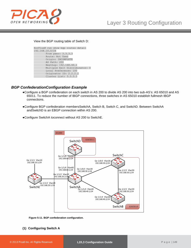
© 2012 Pica8 Inc. All © 2012 Pica8 Inc. All
Layer 3 Routing Configuration
© 2013 Pica8 Inc. All Rights Reserved. L2/L3 Configuration Guide
P a g e | 149
View the BGP routing table of Switch D: XorPlus# run show bgp routes detail
192.168.10.0/24
From peer: 3.3.3.3
Route: Not Used
Origin: INCOMPLETE
AS Path: 200
Nexthop: 192.168.40.1
Multiple Exit Discriminator: 0
Local Preference: 100
Originator ID: 2.2.2.2
Cluster List: 3.3.3.3
BGP ConfederationConfiguration Example
●Configure a BGP confederation on each switch in AS 200 to divide AS 200 into two sub-AS’s: AS 65010 and AS 65011. To reduce the number of IBGP connections, three switches in AS 65010 establish fullmesh IBGP connections.
●Configure BGP confederation membersSwitchA, Switch B, Switch C, and SwitchD. Between SwitchA andSwitchD is an EBGP connection within AS 200.
●Configure SwitchA toconnect without AS 200 to SwitchE.
AS200
AS65010
AS65011
SwitchE SwitchA
SwitchB
SwitchC
Ge-1/1/1 Vlan10192.168.10.1/24
Ge-1/1/2 Vlan20192.168.20.1/24
Ge-1/1/2 Vlan20192.168.20.2/24
Ge-1/0/3 Vlan30192.168.30.1/24
Ge-1/1/4 Vlan40192.168.40.1/24
Ge-1/1/4 Vlan40192.168.40.2/24
Ge-1/0/3 Vlan30192.168.30.2/24
Ge-1/1/5 Vlan50192.168.50.1/24
Ge-1/1/5 Vlan50192.168.50.2/24
SwitchD
Ge-1/1/6 Vlan60192.168.60.1/24
Ge-1/1/6 Vlan60192.168.60.2/24
Figure 5-11. BGP confederation configuration.
(1) Configuring Switch A

© 2012 Pica8 Inc. All © 2012 Pica8 Inc. All
Layer 3 Routing Configuration
© 2013 Pica8 Inc. All Rights Reserved. L2/L3 Configuration Guide
P a g e | 150
Configure the VLAN that each interface belongs to. XorPlus# set vlans vlan-id 20 l3-interface 20
[edit]
XorPlus# set vlans vlan-id 30 l3-interface 30
[edit]
XorPlus# set vlans vlan-id 40 l3-interface 40
[edit]
XorPlus# set vlans vlan-id 60 l3-interface 60
[edit]
XorPlus# commit
Waiting for merging configuration.
Commit OK.
Save done.
[edit]
XorPlus# set interface gigabit-ethernet ge-1/1/2 family ethernet-switching native-vlan-id 20
[edit]
XorPlus# set interface gigabit-ethernet ge-1/1/3 family ethernet-switching native-vlan-id 30
[edit]
XorPlus# set interface gigabit-ethernet ge-1/1/4 family ethernet-switching native-vlan-id 40
[edit]
XorPlus# set interface gigabit-ethernet ge-1/1/6 family ethernet-switching native-vlan-id 60
[edit]
XorPlus# commit
Waiting for merging configuration.
Commit OK.
Save done.
[edit]
XorPlus#
Configure the VLAN interfaces and assign them IP addresses. XorPlus# set vlan-interface interface 20 vif 20 address 192.168.20.2 prefix-length 24
[edit]
XorPlus# set vlan-interface interface 30 vif 30 address 192.168.30.1 prefix-length 24
[edit]
XorPlus# set vlan-interface interface 40 vif 40 address 192.168.40.1 prefix-length 24
[edit]
XorPlus# set vlan-interface interface 60 vif 60 address 192.168.60.1 prefix-length 24
[edit]
XorPlus# commit
Waiting for merging configuration.
Commit OK.
Save done.
[edit]
XorPlus#
Configure EBGP and IBGP connections within confederation AS 200. XorPlus# set protocols bgp bgp-id 2.2.2.2
[edit]
XorPlus# set protocols bgp local-as 65010
[edit]
XorPlus# protocols bgp confederation identifier 200
[edit]
XorPlus# protocols bgp confederation disable false
[edit]
XorPlus# set protocols bgp peer 192.168.30.2 as 65010
[edit]
XorPlus# set protocols bgp peer 192.168.30.2 local-ip 192.168.30.1
[edit]
XorPlus# set protocols bgp peer 192.168.30.2 next-hop-self true
[edit]
XorPlus# set protocols bgp peer 192.168.30.2 confederation-member true
[edit]
XorPlus# set protocols bgp peer 192.168.40.2 as 65010
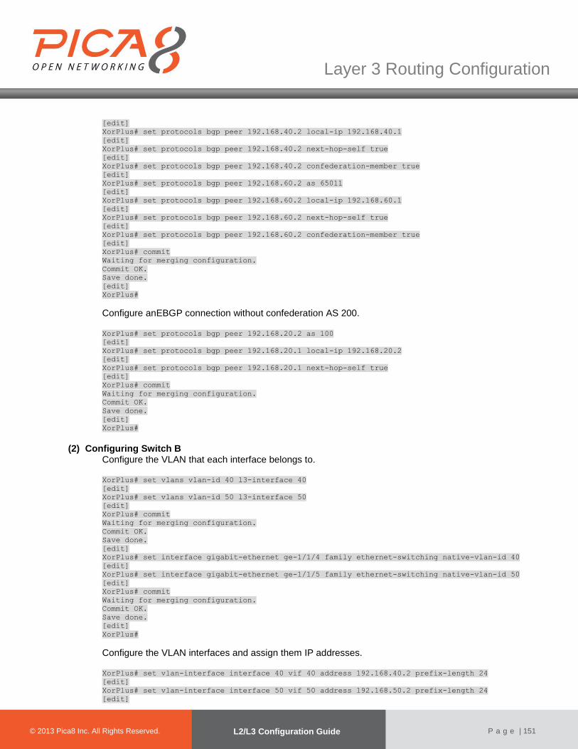
© 2012 Pica8 Inc. All © 2012 Pica8 Inc. All
Layer 3 Routing Configuration
© 2013 Pica8 Inc. All Rights Reserved. L2/L3 Configuration Guide
P a g e | 151
[edit]
XorPlus# set protocols bgp peer 192.168.40.2 local-ip 192.168.40.1
[edit]
XorPlus# set protocols bgp peer 192.168.40.2 next-hop-self true
[edit]
XorPlus# set protocols bgp peer 192.168.40.2 confederation-member true
[edit]
XorPlus# set protocols bgp peer 192.168.60.2 as 65011
[edit]
XorPlus# set protocols bgp peer 192.168.60.2 local-ip 192.168.60.1
[edit]
XorPlus# set protocols bgp peer 192.168.60.2 next-hop-self true
[edit]
XorPlus# set protocols bgp peer 192.168.60.2 confederation-member true
[edit]
XorPlus# commit
Waiting for merging configuration.
Commit OK.
Save done.
[edit]
XorPlus#
Configure anEBGP connection without confederation AS 200. XorPlus# set protocols bgp peer 192.168.20.2 as 100
[edit]
XorPlus# set protocols bgp peer 192.168.20.1 local-ip 192.168.20.2
[edit]
XorPlus# set protocols bgp peer 192.168.20.1 next-hop-self true
[edit]
XorPlus# commit
Waiting for merging configuration.
Commit OK.
Save done.
[edit]
XorPlus#
(2) Configuring Switch B Configure the VLAN that each interface belongs to. XorPlus# set vlans vlan-id 40 l3-interface 40
[edit]
XorPlus# set vlans vlan-id 50 l3-interface 50
[edit]
XorPlus# commit
Waiting for merging configuration.
Commit OK.
Save done.
[edit]
XorPlus# set interface gigabit-ethernet ge-1/1/4 family ethernet-switching native-vlan-id 40
[edit]
XorPlus# set interface gigabit-ethernet ge-1/1/5 family ethernet-switching native-vlan-id 50
[edit]
XorPlus# commit
Waiting for merging configuration.
Commit OK.
Save done.
[edit]
XorPlus#
Configure the VLAN interfaces and assign them IP addresses. XorPlus# set vlan-interface interface 40 vif 40 address 192.168.40.2 prefix-length 24
[edit]
XorPlus# set vlan-interface interface 50 vif 50 address 192.168.50.2 prefix-length 24
[edit]
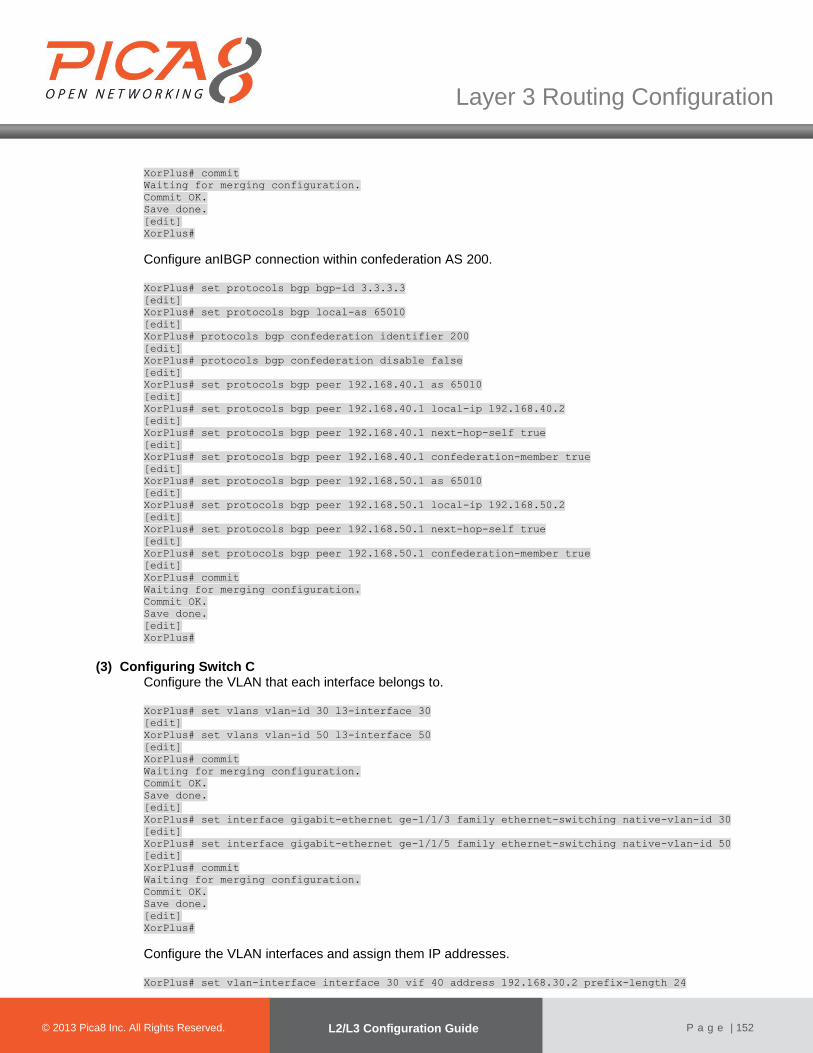
© 2012 Pica8 Inc. All © 2012 Pica8 Inc. All
Layer 3 Routing Configuration
© 2013 Pica8 Inc. All Rights Reserved. L2/L3 Configuration Guide
P a g e | 152
XorPlus# commit
Waiting for merging configuration.
Commit OK.
Save done.
[edit]
XorPlus#
Configure anIBGP connection within confederation AS 200. XorPlus# set protocols bgp bgp-id 3.3.3.3
[edit]
XorPlus# set protocols bgp local-as 65010
[edit]
XorPlus# protocols bgp confederation identifier 200
[edit]
XorPlus# protocols bgp confederation disable false
[edit]
XorPlus# set protocols bgp peer 192.168.40.1 as 65010
[edit]
XorPlus# set protocols bgp peer 192.168.40.1 local-ip 192.168.40.2
[edit]
XorPlus# set protocols bgp peer 192.168.40.1 next-hop-self true
[edit]
XorPlus# set protocols bgp peer 192.168.40.1 confederation-member true
[edit]
XorPlus# set protocols bgp peer 192.168.50.1 as 65010
[edit]
XorPlus# set protocols bgp peer 192.168.50.1 local-ip 192.168.50.2
[edit]
XorPlus# set protocols bgp peer 192.168.50.1 next-hop-self true
[edit]
XorPlus# set protocols bgp peer 192.168.50.1 confederation-member true
[edit]
XorPlus# commit
Waiting for merging configuration.
Commit OK.
Save done.
[edit]
XorPlus#
(3) Configuring Switch C Configure the VLAN that each interface belongs to. XorPlus# set vlans vlan-id 30 l3-interface 30
[edit]
XorPlus# set vlans vlan-id 50 l3-interface 50
[edit]
XorPlus# commit
Waiting for merging configuration.
Commit OK.
Save done.
[edit]
XorPlus# set interface gigabit-ethernet ge-1/1/3 family ethernet-switching native-vlan-id 30
[edit]
XorPlus# set interface gigabit-ethernet ge-1/1/5 family ethernet-switching native-vlan-id 50
[edit]
XorPlus# commit
Waiting for merging configuration.
Commit OK.
Save done.
[edit]
XorPlus#
Configure the VLAN interfaces and assign them IP addresses. XorPlus# set vlan-interface interface 30 vif 40 address 192.168.30.2 prefix-length 24
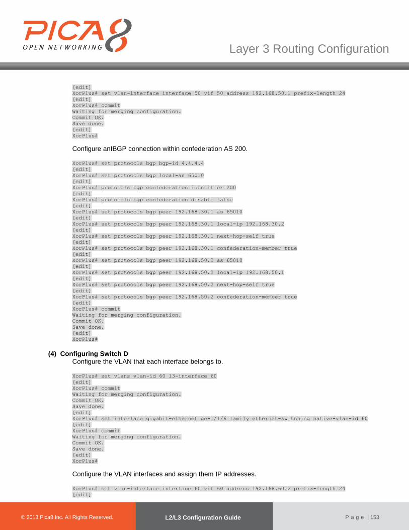
© 2012 Pica8 Inc. All © 2012 Pica8 Inc. All
Layer 3 Routing Configuration
© 2013 Pica8 Inc. All Rights Reserved. L2/L3 Configuration Guide
P a g e | 153
[edit]
XorPlus# set vlan-interface interface 50 vif 50 address 192.168.50.1 prefix-length 24
[edit]
XorPlus# commit
Waiting for merging configuration.
Commit OK.
Save done.
[edit]
XorPlus#
Configure anIBGP connection within confederation AS 200. XorPlus# set protocols bgp bgp-id 4.4.4.4
[edit]
XorPlus# set protocols bgp local-as 65010
[edit]
XorPlus# protocols bgp confederation identifier 200
[edit]
XorPlus# protocols bgp confederation disable false
[edit]
XorPlus# set protocols bgp peer 192.168.30.1 as 65010
[edit]
XorPlus# set protocols bgp peer 192.168.30.1 local-ip 192.168.30.2
[edit]
XorPlus# set protocols bgp peer 192.168.30.1 next-hop-self true
[edit]
XorPlus# set protocols bgp peer 192.168.30.1 confederation-member true
[edit]
XorPlus# set protocols bgp peer 192.168.50.2 as 65010
[edit]
XorPlus# set protocols bgp peer 192.168.50.2 local-ip 192.168.50.1
[edit]
XorPlus# set protocols bgp peer 192.168.50.2 next-hop-self true
[edit]
XorPlus# set protocols bgp peer 192.168.50.2 confederation-member true
[edit]
XorPlus# commit
Waiting for merging configuration.
Commit OK.
Save done.
[edit]
XorPlus#
(4) Configuring Switch D Configure the VLAN that each interface belongs to.
XorPlus# set vlans vlan-id 60 l3-interface 60
[edit]
XorPlus# commit
Waiting for merging configuration.
Commit OK.
Save done.
[edit]
XorPlus# set interface gigabit-ethernet ge-1/1/6 family ethernet-switching native-vlan-id 60
[edit]
XorPlus# commit
Waiting for merging configuration.
Commit OK.
Save done.
[edit]
XorPlus#
Configure the VLAN interfaces and assign them IP addresses. XorPlus# set vlan-interface interface 60 vif 60 address 192.168.60.2 prefix-length 24
[edit]

© 2012 Pica8 Inc. All © 2012 Pica8 Inc. All
Layer 3 Routing Configuration
© 2013 Pica8 Inc. All Rights Reserved. L2/L3 Configuration Guide
P a g e | 154
XorPlus# commit
Waiting for merging configuration.
Commit OK.
Save done.
[edit]
XorPlus#
ConfigureanEBGP connection within confederation AS 200. XorPlus# set protocols bgp bgp-id 5.5.5.5
[edit]
XorPlus# set protocols bgp local-as 65011
[edit]
XorPlus# protocols bgp confederation identifier 200
[edit]
XorPlus# protocols bgp confederation disable false
[edit]
XorPlus# set protocols bgp peer 192.168.60.2 as 65010
[edit]
XorPlus# set protocols bgp peer 192.168.60.2 local-ip 192.168.60.1
[edit]
XorPlus# set protocols bgp peer 192.168.60.2 next-hop-self true
[edit]
XorPlus# set protocols bgp peer 192.168.60.2 confederation-member true
[edit]
XorPlus# commit
Waiting for merging configuration.
Commit OK.
Save done.
[edit]
XorPlus#
(5) Configuring Switch E Configure the VLAN that each interface belongs to. XorPlus# set vlans vlan-id 10 l3-interface 10
[edit]
XorPlus# set vlans vlan-id 20 l3-interface 20
[edit]
XorPlus# commit
Waiting for merging configuration.
Commit OK.
Save done.
[edit]
XorPlus# set interface gigabit-ethernet ge-1/1/1 family ethernet-switching native-vlan-id 10
[edit]
XorPlus# set interface gigabit-ethernet ge-1/1/2 family ethernet-switching native-vlan-id 20
[edit]
XorPlus# commit
Waiting for merging configuration.
Commit OK.
Save done.
[edit]
XorPlus#
Configure the VLAN interfaces and assign them IP addresses. XorPlus# set vlan-interface interface 10 vif 10 address 192.168.10.1 prefix-length 24
[edit]
XorPlus# set vlan-interface interface 20 vif 20 address 192.168.20.1 prefix-length 24
[edit]
XorPlus# commit
Waiting for merging configuration.
Commit OK.
Save done.
[edit]

© 2012 Pica8 Inc. All © 2012 Pica8 Inc. All
Layer 3 Routing Configuration
© 2013 Pica8 Inc. All Rights Reserved. L2/L3 Configuration Guide
P a g e | 155
XorPlus#
ConfigureanEBGP connection. XorPlus# set protocols bgp bgp-id 1.1.1.1
[edit]
XorPlus# set protocols bgp local-as 100
[edit]
XorPlus# set protocols bgp peer 192.168.20.2 as 200
[edit]
XorPlus# set protocols bgp peer 192.168.20.2 local-ip 192.168.20.1
[edit]
XorPlus# set protocols bgp peer 192.168.20.2 next-hop-self true
[edit]
XorPlus# commit
Waiting for merging configuration.
Commit OK.
Save done.
[edit]
XorPlus#
(6) Verifying the configuration View the BGP routing table of Switch B: XorPlus# run show bgp routes detail
192.168.10.0/24
From peer: 2.2.2.2
Route: Not Used
Origin: INCOMPLETE
AS Path: 100
Nexthop: 192.168.20.1
Multiple Exit Discriminator: 0
Local Preference: 100
View the BGP routing table of Switch D: XorPlus# run show bgp routes detail
192.168.10.0/24
From peer: 15.15.15.15
Route: Not Used
Origin: INCOMPLETE
AS Path: (65010) 100
Nexthop: 192.168.30.2
Local Preference: 100
BGP Load Balancing Configuration Example
● Configure load balancing on SwitchA.
● Configure EBGP connections between SwitchB and SwitchA, andbetween SwitchB and SwitchD.
● Configure EBGP connections between SwitchC and SwitchA, and between SwitchC and SwitchD.
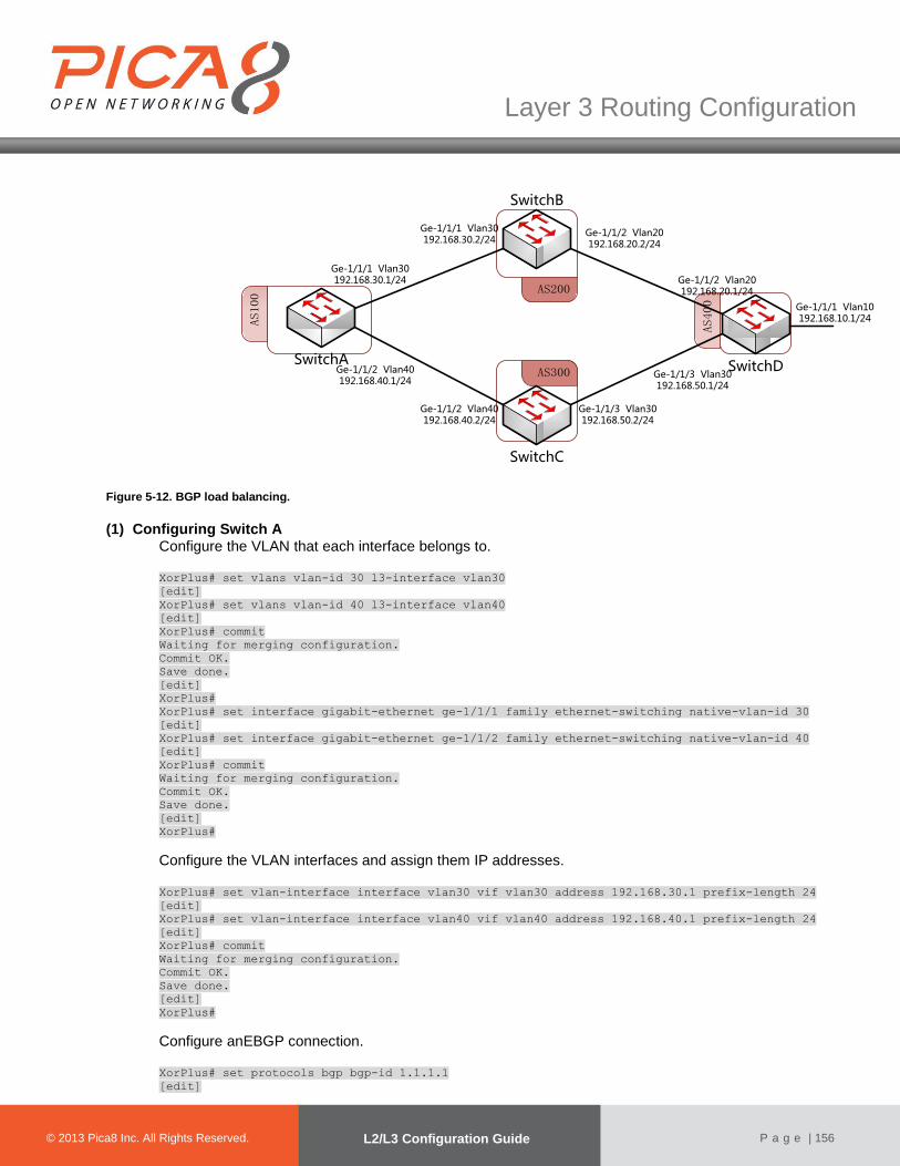
© 2012 Pica8 Inc. All © 2012 Pica8 Inc. All
Layer 3 Routing Configuration
© 2013 Pica8 Inc. All Rights Reserved. L2/L3 Configuration Guide
P a g e | 156
AS100
AS200
AS300
AS400
SwitchDSwitchA
SwitchC
SwitchB
Ge-1/1/1 Vlan10192.168.10.1/24
Ge-1/1/2 Vlan20192.168.20.1/24
Ge-1/1/2 Vlan20192.168.20.2/24
Ge-1/1/1 Vlan30192.168.30.1/24
Ge-1/1/2 Vlan40192.168.40.1/24
Ge-1/1/2 Vlan40192.168.40.2/24
Ge-1/1/1 Vlan30192.168.30.2/24
Ge-1/1/3 Vlan30192.168.50.2/24
Ge-1/1/3 Vlan30192.168.50.1/24
Figure 5-12. BGP load balancing.
(1) Configuring Switch A Configure the VLAN that each interface belongs to. XorPlus# set vlans vlan-id 30 l3-interface vlan30
[edit]
XorPlus# set vlans vlan-id 40 l3-interface vlan40
[edit]
XorPlus# commit
Waiting for merging configuration.
Commit OK.
Save done.
[edit]
XorPlus#
XorPlus# set interface gigabit-ethernet ge-1/1/1 family ethernet-switching native-vlan-id 30
[edit]
XorPlus# set interface gigabit-ethernet ge-1/1/2 family ethernet-switching native-vlan-id 40
[edit]
XorPlus# commit
Waiting for merging configuration.
Commit OK.
Save done.
[edit]
XorPlus#
Configure the VLAN interfaces and assign them IP addresses. XorPlus# set vlan-interface interface vlan30 vif vlan30 address 192.168.30.1 prefix-length 24
[edit]
XorPlus# set vlan-interface interface vlan40 vif vlan40 address 192.168.40.1 prefix-length 24
[edit]
XorPlus# commit
Waiting for merging configuration.
Commit OK.
Save done.
[edit]
XorPlus#
Configure anEBGP connection. XorPlus# set protocols bgp bgp-id 1.1.1.1
[edit]
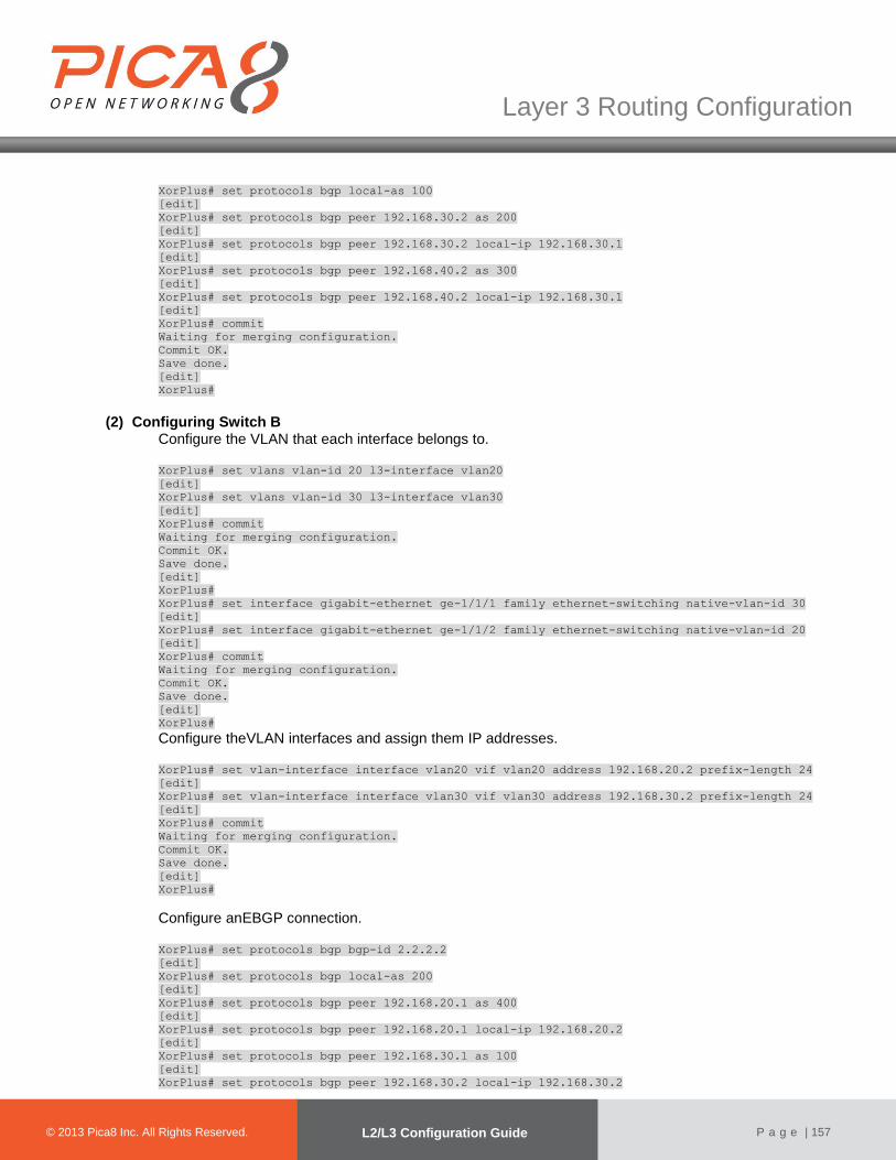
© 2012 Pica8 Inc. All © 2012 Pica8 Inc. All
Layer 3 Routing Configuration
© 2013 Pica8 Inc. All Rights Reserved. L2/L3 Configuration Guide
P a g e | 157
XorPlus# set protocols bgp local-as 100
[edit]
XorPlus# set protocols bgp peer 192.168.30.2 as 200
[edit]
XorPlus# set protocols bgp peer 192.168.30.2 local-ip 192.168.30.1
[edit]
XorPlus# set protocols bgp peer 192.168.40.2 as 300
[edit]
XorPlus# set protocols bgp peer 192.168.40.2 local-ip 192.168.30.1
[edit]
XorPlus# commit
Waiting for merging configuration.
Commit OK.
Save done.
[edit]
XorPlus#
(2) Configuring Switch B Configure the VLAN that each interface belongs to. XorPlus# set vlans vlan-id 20 l3-interface vlan20
[edit]
XorPlus# set vlans vlan-id 30 l3-interface vlan30
[edit]
XorPlus# commit
Waiting for merging configuration.
Commit OK.
Save done.
[edit]
XorPlus#
XorPlus# set interface gigabit-ethernet ge-1/1/1 family ethernet-switching native-vlan-id 30
[edit]
XorPlus# set interface gigabit-ethernet ge-1/1/2 family ethernet-switching native-vlan-id 20
[edit]
XorPlus# commit
Waiting for merging configuration.
Commit OK.
Save done.
[edit]
XorPlus#
Configure theVLAN interfaces and assign them IP addresses.
XorPlus# set vlan-interface interface vlan20 vif vlan20 address 192.168.20.2 prefix-length 24
[edit]
XorPlus# set vlan-interface interface vlan30 vif vlan30 address 192.168.30.2 prefix-length 24
[edit]
XorPlus# commit
Waiting for merging configuration.
Commit OK.
Save done.
[edit]
XorPlus#
Configure anEBGP connection.
XorPlus# set protocols bgp bgp-id 2.2.2.2
[edit]
XorPlus# set protocols bgp local-as 200
[edit]
XorPlus# set protocols bgp peer 192.168.20.1 as 400
[edit]
XorPlus# set protocols bgp peer 192.168.20.1 local-ip 192.168.20.2
[edit]
XorPlus# set protocols bgp peer 192.168.30.1 as 100
[edit]
XorPlus# set protocols bgp peer 192.168.30.2 local-ip 192.168.30.2
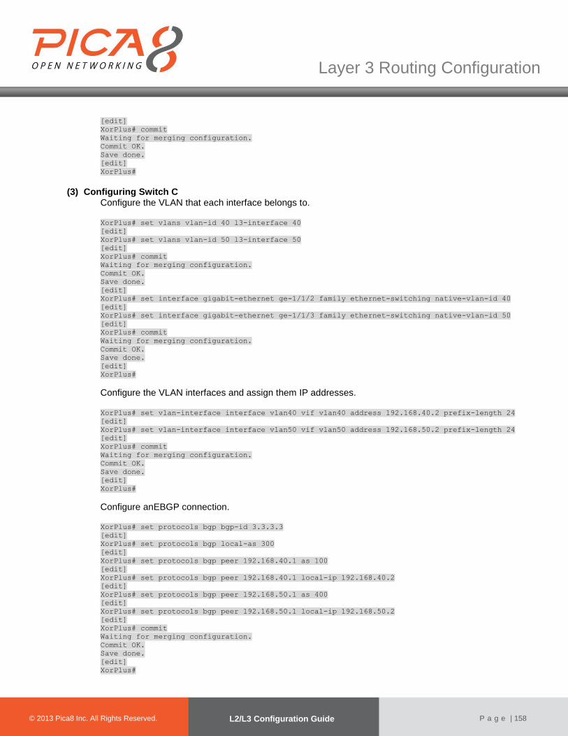
© 2012 Pica8 Inc. All © 2012 Pica8 Inc. All
Layer 3 Routing Configuration
© 2013 Pica8 Inc. All Rights Reserved. L2/L3 Configuration Guide
P a g e | 158
[edit]
XorPlus# commit
Waiting for merging configuration.
Commit OK.
Save done.
[edit]
XorPlus#
(3) Configuring Switch C Configure the VLAN that each interface belongs to. XorPlus# set vlans vlan-id 40 l3-interface 40
[edit]
XorPlus# set vlans vlan-id 50 l3-interface 50
[edit]
XorPlus# commit
Waiting for merging configuration.
Commit OK.
Save done.
[edit]
XorPlus# set interface gigabit-ethernet ge-1/1/2 family ethernet-switching native-vlan-id 40
[edit]
XorPlus# set interface gigabit-ethernet ge-1/1/3 family ethernet-switching native-vlan-id 50
[edit]
XorPlus# commit
Waiting for merging configuration.
Commit OK.
Save done.
[edit]
XorPlus#
Configure the VLAN interfaces and assign them IP addresses. XorPlus# set vlan-interface interface vlan40 vif vlan40 address 192.168.40.2 prefix-length 24
[edit]
XorPlus# set vlan-interface interface vlan50 vif vlan50 address 192.168.50.2 prefix-length 24
[edit]
XorPlus# commit
Waiting for merging configuration.
Commit OK.
Save done.
[edit]
XorPlus#
Configure anEBGP connection. XorPlus# set protocols bgp bgp-id 3.3.3.3
[edit]
XorPlus# set protocols bgp local-as 300
[edit]
XorPlus# set protocols bgp peer 192.168.40.1 as 100
[edit]
XorPlus# set protocols bgp peer 192.168.40.1 local-ip 192.168.40.2
[edit]
XorPlus# set protocols bgp peer 192.168.50.1 as 400
[edit]
XorPlus# set protocols bgp peer 192.168.50.1 local-ip 192.168.50.2
[edit]
XorPlus# commit
Waiting for merging configuration.
Commit OK.
Save done.
[edit]
XorPlus#

© 2012 Pica8 Inc. All © 2012 Pica8 Inc. All
Layer 3 Routing Configuration
© 2013 Pica8 Inc. All Rights Reserved. L2/L3 Configuration Guide
P a g e | 159
(4) Configuring Switch D Configure the VLAN that each interface belongs to. XorPlus# set vlans vlan-id 10 l3-interface vlan10
[edit]
XorPlus# set vlans vlan-id 20 l3-interface vlan20
[edit]
XorPlus# set vlans vlan-id 50 l3-interface vlan50
[edit]
XorPlus# commit
Waiting for merging configuration.
Commit OK.
Save done.
[edit]
XorPlus# set interface gigabit-ethernet ge-1/1/1 family ethernet-switching native-vlan-id 10
[edit]
XorPlus# set interface gigabit-ethernet ge-1/1/2 family ethernet-switching native-vlan-id 20
[edit]
XorPlus# set interface gigabit-ethernet ge-1/1/3 family ethernet-switching native-vlan-id 50
[edit]
XorPlus# commit
Waiting for merging configuration.
Commit OK.
Save done.
[edit]
XorPlus#
Configure the VLAN interfaces and assign them IP addresses. XorPlus# set vlan-interface interface vlan10 vif vlan10 address 192.168.10.1 prefix-length 24
[edit]
XorPlus# set vlan-interface interface vlan20 vif vlan20 address 192.168.20.1 prefix-length 24
[edit]
XorPlus# set vlan-interface interface vlan50 vif vlan50 address 192.168.50.1 prefix-length 24
[edit]
XorPlus# commit
Waiting for merging configuration.
Commit OK.
Save done.
[edit]
XorPlus#
ConfigureanEBGP connection. XorPlus# set protocols bgp bgp-id 4.4.4.4
[edit]
XorPlus# set protocols bgp local-as 400
[edit]
XorPlus# set protocols bgp peer 192.168.20.2 as 200
[edit]
XorPlus# set protocols bgp peer 192.168.20.2 local-ip 192.168.20.1
[edit]
XorPlus# set protocols bgp peer 192.168.50.2 as 300
[edit]
XorPlus# set protocols bgp peer 192.168.50.2 local-ip 192.168.50.1
[edit]
XorPlus# commit
Waiting for merging configuration.
Commit OK.
Save done.
[edit]
XorPlus#
(5) ViewingBGP peer statuseson Switch B

© 2012 Pica8 Inc. All © 2012 Pica8 Inc. All
Layer 3 Routing Configuration
© 2013 Pica8 Inc. All Rights Reserved. L2/L3 Configuration Guide
P a g e | 160
XorPlus# run show bgp peers detail
Peer 2: local 192.168.20.2/179 remote 192.168.20.1/39912
Peer ID: 1.1.1.1
Peer State: ESTABLISHED
Admin State: START
Negotiated BGP Version: 4
Peer AS Number: 100
Updates Received: 20, Updates Sent: 2
Messages Received: 634, Messages Sent: 611
Time since last received update: 1685 seconds
Number of transitions to ESTABLISHED: 1
Time since last entering ESTABLISHED state: 15995 seconds
Retry Interval: 120 seconds
Hold Time: 90 seconds, Keep Alive Time: 30 seconds
Configured Hold Time: 90 seconds, Configured Keep Alive Time: 30 seconds
Minimum AS Origination Interval: 0 seconds
Minimum Route Advertisement Interval: 0 seconds
Peer 2: local 192.168.30.2/16808 remote 192.168.30.1/179
Peer ID: 4.4.4.4
Peer State: ESTABLISHED
Admin State: START
Negotiated BGP Version: 4
Peer AS Number: 100
Updates Received: 20, Updates Sent: 2
Messages Received: 634, Messages Sent: 611
Time since last received update: 1685 seconds
Number of transitions to ESTABLISHED: 1
Time since last entering ESTABLISHED state: 15995 seconds
Retry Interval: 120 seconds
Hold Time: 90 seconds, Keep Alive Time: 30 seconds
Configured Hold Time: 90 seconds, Configured Keep Alive Time: 30 seconds
Minimum AS Origination Interval: 0 seconds
Minimum Route Advertisement Interval: 0 seconds
(6) Viewing BGP peer statusesonSwitch C
XorPlus# run show bgp peers detail
Peer 2: local 192.168.40.2/179 remote 192.168.40.1/38815
Peer ID: 1.1.1.1
Peer State: ESTABLISHED
Admin State: START
Negotiated BGP Version: 4
Peer AS Number: 100
Updates Received: 20, Updates Sent: 2
Messages Received: 634, Messages Sent: 611
Time since last received update: 1685 seconds
Number of transitions to ESTABLISHED: 1
Time since last entering ESTABLISHED state: 15995 seconds
Retry Interval: 120 seconds
Hold Time: 90 seconds, Keep Alive Time: 30 seconds
Configured Hold Time: 90 seconds, Configured Keep Alive Time: 30 seconds
Minimum AS Origination Interval: 0 seconds
Minimum Route Advertisement Interval: 0 seconds
Peer 2: local 192.168.50.2/49923 remote 192.168.50.1/179
Peer ID: 4.4.4.4
Peer State: ESTABLISHED
Admin State: START
Negotiated BGP Version: 4
Peer AS Number: 100
Updates Received: 20, Updates Sent: 2
Messages Received: 634, Messages Sent: 611
Time since last received update: 1685 seconds
Number of transitions to ESTABLISHED: 1
Time since last entering ESTABLISHED state: 15995 seconds
Retry Interval: 120 seconds
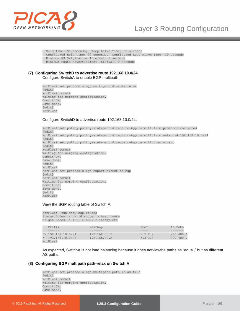
© 2012 Pica8 Inc. All © 2012 Pica8 Inc. All
Layer 3 Routing Configuration
© 2013 Pica8 Inc. All Rights Reserved. L2/L3 Configuration Guide
P a g e | 161
Hold Time: 90 seconds, Keep Alive Time: 30 seconds
Configured Hold Time: 90 seconds, Configured Keep Alive Time: 30 seconds
Minimum AS Origination Interval: 0 seconds
Minimum Route Advertisement Interval: 0 seconds
(7) Configuring SwitchD to advertise route 192.168.10.0/24 Configure SwitchA to enable BGP multipath: XorPlus# set protocols bgp multipath disable false
[edit]
XorPlus# commit
Waiting for merging configuration.
Commit OK.
Save done.
[edit]
XorPlus#
Configure SwitchD to advertise route 192.168.10.0/24: XorPlus# set policy policy-statement direct-to-bgp term t1 from protocol connected
[edit]
XorPlus# set policy policy-statement direct-to-bgp term t1 from network4 192.168.10.0/24
[edit]
XorPlus# set policy policy-statement direct-to-bgp term t1 then accept
[edit]
XorPlus# commit
Waiting for merging configuration.
Commit OK.
Save done.
[edit]
XorPlus#
XorPlus# set protocols bgp export direct-to-bgp
[edit]
XorPlus# commit
Waiting for merging configuration.
Commit OK.
Save done.
[edit]
XorPlus#
View the BGP routing table of Switch A: XorPlus# run show bgp routes
Status Codes: * valid route, > best route
Origin Codes: i IGP, e EGP, ? incomplete
Prefix Nexthop Peer AS Path
------ ------- ---- -------
*> 192.168.10.0/24 192.168.30.2 2.2.2.2 200 400 ?
* 192.168.10.0/24 192.168.40.2 3.3.3.3 200 400 ?
XorPlus#
As expected, SwitchA is not load balancing because it does notviewthe paths as “equal,” but as different AS paths.
(8) Configuring BGP multipath path-relax on Switch A
XorPlus# set protocols bgp multipath path-relax true
[edit]
XorPlus# commit
Waiting for merging configuration.
Commit OK.
Save done.
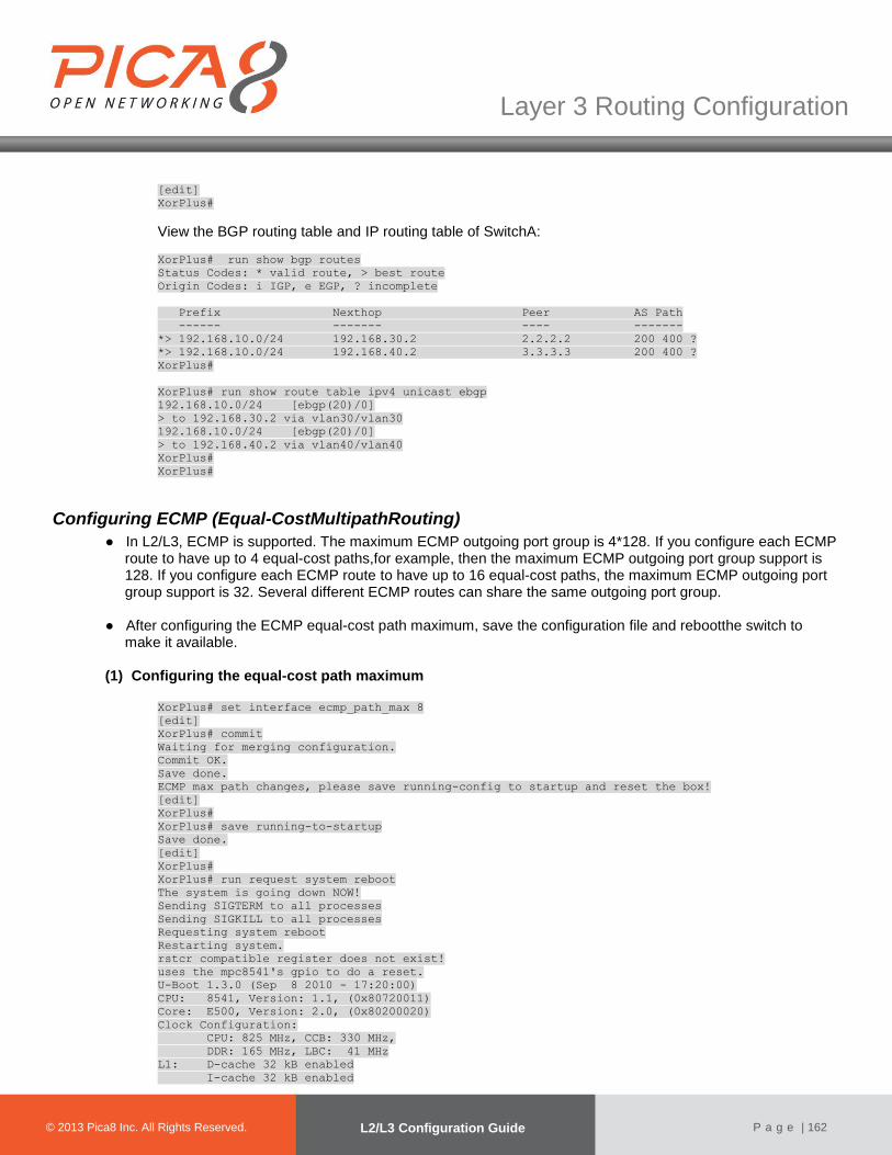
© 2012 Pica8 Inc. All © 2012 Pica8 Inc. All
Layer 3 Routing Configuration
© 2013 Pica8 Inc. All Rights Reserved. L2/L3 Configuration Guide
P a g e | 162
[edit]
XorPlus#
View the BGP routing table and IP routing table of SwitchA:
XorPlus# run show bgp routes
Status Codes: * valid route, > best route
Origin Codes: i IGP, e EGP, ? incomplete
Prefix Nexthop Peer AS Path
------ ------- ---- -------
*> 192.168.10.0/24 192.168.30.2 2.2.2.2 200 400 ?
*> 192.168.10.0/24 192.168.40.2 3.3.3.3 200 400 ?
XorPlus#
XorPlus# run show route table ipv4 unicast ebgp
192.168.10.0/24 [ebgp(20)/0]
> to 192.168.30.2 via vlan30/vlan30
192.168.10.0/24 [ebgp(20)/0]
> to 192.168.40.2 via vlan40/vlan40
XorPlus#
XorPlus#
Configuring ECMP (Equal-CostMultipathRouting)
● In L2/L3, ECMP is supported. The maximum ECMP outgoing port group is 4*128. If you configure each ECMP route to have up to 4 equal-cost paths,for example, then the maximum ECMP outgoing port group support is 128. If you configure each ECMP route to have up to 16 equal-cost paths, the maximum ECMP outgoing port group support is 32. Several different ECMP routes can share the same outgoing port group.
● After configuring the ECMP equal-cost path maximum, save the configuration file and rebootthe switch to
make it available.
(1) Configuring the equal-cost path maximum
XorPlus# set interface ecmp_path_max 8
[edit]
XorPlus# commit
Waiting for merging configuration.
Commit OK.
Save done.
ECMP max path changes, please save running-config to startup and reset the box!
[edit]
XorPlus#
XorPlus# save running-to-startup
Save done.
[edit]
XorPlus#
XorPlus# run request system reboot
The system is going down NOW!
Sending SIGTERM to all processes
Sending SIGKILL to all processes
Requesting system reboot
Restarting system.
rstcr compatible register does not exist!
uses the mpc8541's gpio to do a reset.
U-Boot 1.3.0 (Sep 8 2010 - 17:20:00)
CPU: 8541, Version: 1.1, (0x80720011)
Core: E500, Version: 2.0, (0x80200020)
Clock Configuration:
CPU: 825 MHz, CCB: 330 MHz,
DDR: 165 MHz, LBC: 41 MHz
L1: D-cache 32 kB enabled
I-cache 32 kB enabled

© 2012 Pica8 Inc. All © 2012 Pica8 Inc. All
Layer 3 Routing Configuration
© 2013 Pica8 Inc. All Rights Reserved. L2/L3 Configuration Guide
P a g e | 163
I2C: ready
DRAM: Initializing
(2) Configuringstatic ECMP routing
XorPlus# set vlans vlan-id 2
[edit]
XorPlus# set vlans vlan-id 3
[edit]
XorPlus# set vlans vlan-id 4
[edit]
XorPlus# set interface gigabit-ethernet ge-1/1/3 family ethernet-switching native-vlan-id 2
[edit]
XorPlus# set interface gigabit-ethernet ge-1/1/4 family ethernet-switching native-vlan-id 3
[edit]
XorPlus# set interface gigabit-ethernet ge-1/1/5 family ethernet-switching native-vlan-id 4
[edit]
XorPlus# set vlans vlan-id 2 l3-interface vlan-2
[edit]
XorPlus# set vlans vlan-id 3 l3-interface vlan-3
[edit]
XorPlus# set vlans vlan-id 4 l3-interface vlan-4
[edit]
XorPlus# set vlan-interface interface vlan-2 address 10.10.60.10 prefix-length 24
[edit]
XorPlus# set vlan-interface interface vlan-3 address 10.10.61.10 prefix-length 24
[edit]
XorPlus# set vlan-interface interface vlan-4 address 10.10.62.10 prefix-length 24
[edit]
XorPlus# commit
Waiting for merging configuration.
Commit OK.
Save done.
[edit]
XorPlus# set protocols static route 10.10.51.0/24 next-hop 10.10.61.20
[edit]
XorPlus# set protocols static route 10.10.51.0/24 qualified-next-hop 10.10.62.20 metric 1
[edit]
XorPlus# commit
Waiting for merging configuration.
Commit OK.
Save done.
[edit]
XorPlus#
You can check the static ECMP route for 10.10.51.0/24 in the RIB.
XorPlus# run show route table ipv4 unicast final
10.10.51.0/24 [static(1)/1]
> to 10.10.61.20 via vlan-3/vlan-3
10.10.51.0/24 [static(1)/1]
> to 10.10.62.20 via vlan-4/vlan-4
10.10.60.0/24 [connected(0)/0]
> via vlan-2/vlan-2
10.10.61.0/24 [connected(0)/0]
> via vlan-3/vlan-3
10.10.62.0/24 [connected(0)/0]
> via vlan-4/vlan-4
(3) Configuring ECMP hash fields In the default setting, all fields are hashed by“ip-source,” “port-destination,” “port-source,” and “vlan.” You can enable additional fields as shown below: XorPlus# set interface ecmp hash-mapping field ingress-interface disable false
[edit]
XorPlus# set interface ecmp hash-mapping field ip-destination disable false

© 2012 Pica8 Inc. All © 2012 Pica8 Inc. All
Layer 3 Routing Configuration
© 2013 Pica8 Inc. All Rights Reserved. L2/L3 Configuration Guide
P a g e | 164
[edit]
XorPlus# set interface ecmp hash-mapping field ip-protocol disable false
[edit]
XorPlus# set interface ecmp hash-mapping field ip-source disable false
[edit]
XorPlus# set interface ecmp hash-mapping field port-destination disable false
[edit]
XorPlus# set interface ecmp hash-mapping field port-source disable false
[edit]
XorPlus# set interface ecmp hash-mapping field vlan disable false
[edit]
XorPlus# commit
Waiting for merging configuration.
Commit OK.
Save done.
[edit]
XorPlus#
Configuring VRRP (Virtual Router Redundancy Protocol)
In L2/L3, VRRP is supported, for both preempt and non-preempt parameters. (1) Configuring VRRP
In the configuration below, a virtual router with IP 192.168.1.5/24 has been created.You can configureVRRP preemption and the VRRP priority. XorPlus# set vlans vlan-id 2
[edit]
XorPlus# set vlans vlan-id 3
[edit]
XorPlus# set interface gigabit-ethernet ge-1/1/2 family ethernet-switching native-vlan-id 2
[edit]
XorPlus# set interface gigabit-ethernet ge-1/1/3 family ethernet-switching native-vlan-id 3
[edit]
XorPlus# set vlans vlan-id 2 l3-interface vlan-2
[edit]
XorPlus# set vlans vlan-id 3 l3-interface vlan-3
[edit]
XorPlus# set vlan-interface interface vlan-2vif vlan-2 address 192.168.1.1 prefix-length 24
[edit]
XorPlus# set vlan-interface interface vlan-3vif vlan-3 address 192.168.2.1 prefix-length 24
[edit]
XorPlus# commit
Waiting for merging configuration.
Commit OK.
Save done.
[edit]
XorPlus# set protocols vrrp interface vlan-2 vrid 1
[edit]
XorPlus# set protocols vrrp interface vlan-2vif vlan-2 vrid 1 ip 192.168.1.5 prefix-length 24
[edit]
XorPlus# set protocols vrrp interface vlan-2vif vlan-2 vrid 1 preempt true
[edit]
XorPlus# set protocols vrrp interface vlan-2vif vlan-2 vrid 1 priority 100
[edit]
XorPlus# commit
Waiting for merging configuration.
Commit OK.
Save done.
[edit]
XorPlus#
You can check the VRRP configuration.
XorPlus# run show vrrp vlan-2

© 2012 Pica8 Inc. All © 2012 Pica8 Inc. All
Layer 3 Routing Configuration
© 2013 Pica8 Inc. All Rights Reserved. L2/L3 Configuration Guide
P a g e | 165
Interface vlan-2
Vif vlan-2
VRID 1
State master
Master IP 192.168.1.1
XorPlus#
IPv6 Neighbor Configuration (1) Configuring the IPv6 neighbor aging time
You can configure the IPv6 neighbor aging time. The neighbor will be removed after the timer has expired. XorPlus# set protocols neighbour aging-time 480
[edit]
XorPlus# commit
Waiting for merging configuration.
Commit OK.
Save done.
[edit]
XorPlus#
(2) Configuring a static IPv6 neighbor Youcan configure a static IPv6 neighbor in a specified interface. XorPlus# set vlans vlan-id 2 l3-interface vlan-2
[edit]
XorPlus# set protocols neighbour interface vlan-2 vif vlan-2 address 2001::01 mac-address
22:22:22:22:22:22
[edit]
XorPlus# commit
Waiting for merging configuration.
Commit OK.
Save done.
[edit]
XorPlus# run show ipv6-neighbors static
aging-time(seconds): 480
Address HW Address Interface
--------------------------------------- ----------------- ---------
2001::1 22:22:22:22:22:22 vlan-2
XorPlus#
(3) Configuring IPv6 routeradvertisement You can manuallyenable routeradvertisement messages. XorPlus# set vlans vlan-id 2 l3-interface vlan-2
[edit]
XorPlus# set vlan-interface interface vlan1 router-advertisement disable false
[edit]
XorPlus# commit
Waiting for merging configuration.
Commit OK.
Save done.
[edit]
XorPlus#
IPv6 Static Routing Configuration
● In L2/L3, IPv6 static routing is supported. The IPv6 for OSPFv3 and RIPng will be supported soon. ●In P-3290 and P-3780, you should configure the link-local IPv6 address,otherwise all the IPv6 interfaces will
share the same link-local address. This problem will be fixed in afuture version.

© 2012 Pica8 Inc. All © 2012 Pica8 Inc. All
Layer 3 Routing Configuration
© 2013 Pica8 Inc. All Rights Reserved. L2/L3 Configuration Guide
P a g e | 166
(1) Configuring a static route for IPv6 Youcan configure the link-local address and global address for a VLAN interface. XorPlus# set vlans vlan-id 2
[edit]
XorPlus# set vlans vlan-id 3
[edit]
XorPlus# set interface gigabit-ethernet ge-1/1/3 family ethernet-switching native-vlan-id 2
[edit]
XorPlus# set interface gigabit-ethernet ge-1/1/4 family ethernet-switching native-vlan-id 3
[edit]
XorPlus# set vlans vlan-id 2 l3-interface vlan-2
[edit]
XorPlus# set vlans vlan-id 3 l3-interface vlan-3
[edit]
XorPlus# set vlan-interface interface vlan-2vif vlan-2 address 2001:db8:3c4d:5:60:ff:73:87
prefix-length 64
[edit]
XorPlus# set vlan-interface interface vlan-2vif vlan-2 address fe80::ca0a:a9ff:fe04:4931 prefix-
length 64
[edit]
XorPlus# set vlan-interface interface vlan-3vif vlan-3 address 2001:db8:3c4d:6:0:ff:73:87 prefix-
length 64
[edit]
XorPlus# set vlan-interface interface vlan-3vif vlan-3 address fe80::ca0a:a9ff:4:4932 prefix-
length 64
[edit]
XorPlus# commit
Waiting for merging configuration.
Commit OK.
Save done.
[edit]
XorPlus# set protocols static route 2001:db8:3c4d:7::/64 next-hop 2001:db8:3c4d:5:60:d6ff:73:89
[edit]
XorPlus# commit
Waiting for merging configuration.
Commit OK.
Save done.
[edit]
XorPlus#
Then verify the IPv6 static route in the RIB: XorPlus# run show route table ipv6 unicast final
2001:db8:3c4d:5::/64[connected(0)/0]
> via vlan-2/vlan-2
2001:db8:3c4d:6::/64[connected(0)/0]
> via vlan-3/vlan-3
fe80::/64 [connected(0)/0]
> via vlan-3/vlan-3
fe80::/64 [connected(0)/0]
> via vlan-2/vlan-2
OSPFv3 Routing Protocol Configuration
In XorPlus, OSPFv3 is supported.
(1) Configuring the router ID
XorPlus# set protocols ospf6 instance-id 1
[edit]
XorPlus# commit
Waiting for merging configuration.
Commit OK.

© 2012 Pica8 Inc. All © 2012 Pica8 Inc. All
Layer 3 Routing Configuration
© 2013 Pica8 Inc. All Rights Reserved. L2/L3 Configuration Guide
P a g e | 167
Save done.
[edit]
(2) ConfiguringanOSPF area and area-type Area 0.0.0.0 is the backbone area of OSPF; each OSPF domain should have the area 0.0.0.0. Area types includes normal, stub,and NSSA.
XorPlus# set protocols ospf6 area 0.0.0.0 area-type normal
[edit]
XorPlus# set protocols ospf6 area 1.1.1.1 area-type stub
[edit]
XorPlus# set protocols ospf6 area 2.2.2.2 area-type nssa
[edit]
XorPlus# commit
Waiting for merging configuration.
Commit OK.
Save done.
[edit]
XorPlus#
(3) ConfiguringOSPF interfaces
XorPlus# set vlans vlan-id 2 l3-interface vlan-2
[edit]
XorPlus# set vlans vlan-id 3 l3-interface vlan-3
[edit]
XorPlus# set vlan-interface interface vlan-2 vif vlan-2 address 2001::15 prefix-length 64
[edit]
XorPlus# set vlan-interface interface vlan-3 vif vlan-3 address 2002::15 prefix-length 64
[edit]
XorPlus# set interface gigabit-ethernet ge-1/1/1 family ethernet-switching native-vlan-id 2
[edit]
XorPlus# set interface gigabit-ethernet ge-1/1/2 family ethernet-switching native-vlan-id 3
[edit]
XorPlus# set protocols ospf6 area 0.0.0.0 interface vlan-2 vif vlan-2 address 2001::15
[edit]
XorPlus# set protocols ospf6 area 0.0.0.0 interface vlan-3 vif vlan-3 address 2002::15
[edit]
XorPlus# set protocols ospf6 instance-id 1
[edit]
XorPlus# set protocols ospf6 router-id 1.1.1.1
[edit]
XorPlus# commit
Waiting for merging configuration.
Commit OK.
Save done.
[edit]
XorPlus#
XorPlus# run show ospf6 interface
Interface State Area DR ID BDR ID Nbrs
--------- -------- --------------- --------------- --------------- ----
vlan-2 Down 0.0.0.0 0.0.0.0 0.0.0.0 0
vlan-3 Down 0.0.0.0 0.0.0.0 0.0.0.0 0
(4) Configuring additional OSPF interface parameters You can also configure additional OSPF interfaceparameters (hello-interval, interface-cost, static neighbor, priority, retransmit-interval, router-dead-interval, and transmit-delay).
XorPlus# set protocols ospf6 area 0.0.0.0 interface vlan-2 vif vlan-2 hello-interval 10
[edit]
XorPlus# set protocols ospf6 area 0.0.0.0 interface vlan-2 vif vlan-2 interface-cost 8
[edit]
XorPlus# set protocols ospf6 area 0.0.0.0 interface vlan-2 vif vlan-2 transmit-delay 2
[edit]
XorPlus# commit
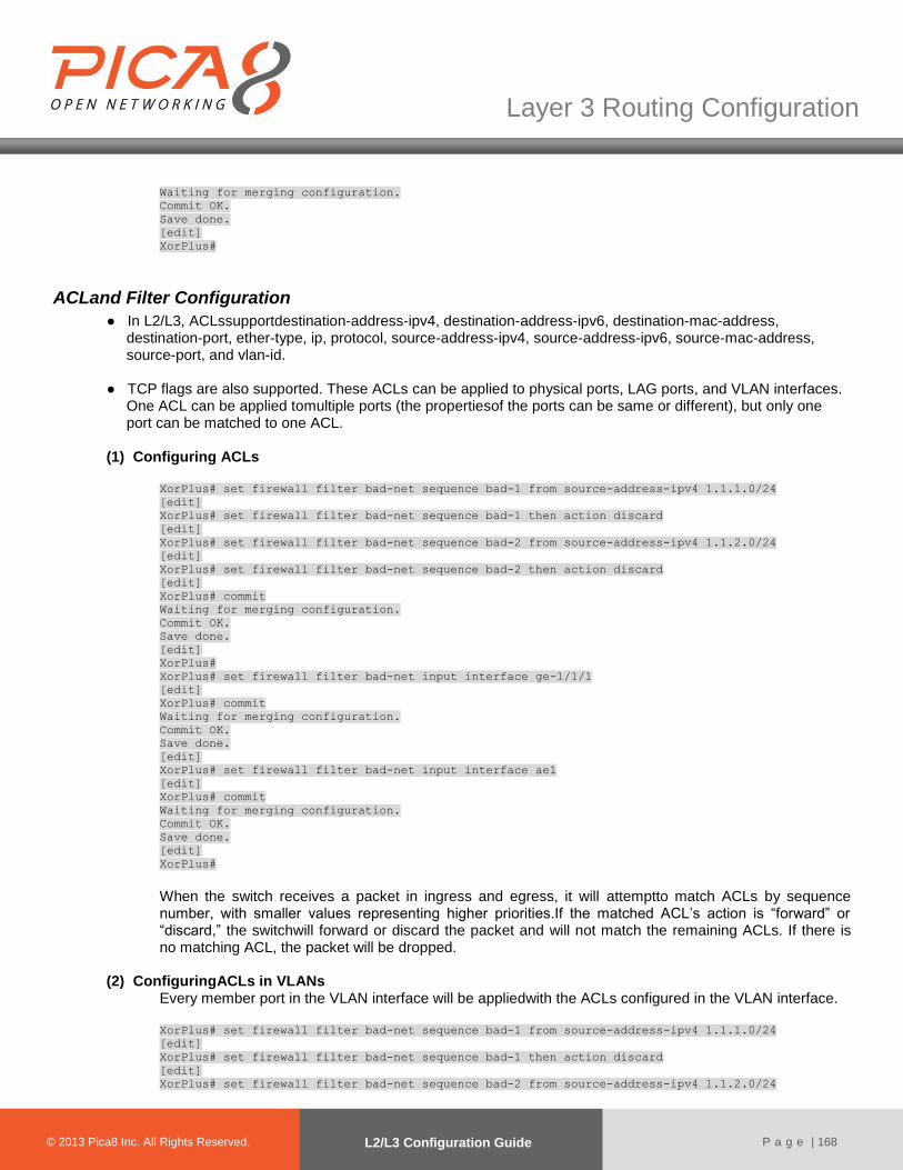
© 2012 Pica8 Inc. All © 2012 Pica8 Inc. All
Layer 3 Routing Configuration
© 2013 Pica8 Inc. All Rights Reserved. L2/L3 Configuration Guide
P a g e | 168
Waiting for merging configuration.
Commit OK.
Save done.
[edit]
XorPlus#
ACLand Filter Configuration
● In L2/L3, ACLssupportdestination-address-ipv4, destination-address-ipv6, destination-mac-address, destination-port, ether-type, ip, protocol, source-address-ipv4, source-address-ipv6, source-mac-address, source-port, and vlan-id.
● TCP flags are also supported. These ACLs can be applied to physical ports, LAG ports, and VLAN interfaces.
One ACL can be applied tomultiple ports (the propertiesof the ports can be same or different), but only one port can be matched to one ACL.
(1) Configuring ACLs
XorPlus# set firewall filter bad-net sequence bad-1 from source-address-ipv4 1.1.1.0/24
[edit]
XorPlus# set firewall filter bad-net sequence bad-1 then action discard
[edit]
XorPlus# set firewall filter bad-net sequence bad-2 from source-address-ipv4 1.1.2.0/24
[edit]
XorPlus# set firewall filter bad-net sequence bad-2 then action discard
[edit]
XorPlus# commit
Waiting for merging configuration.
Commit OK.
Save done.
[edit]
XorPlus#
XorPlus# set firewall filter bad-net input interface ge-1/1/1
[edit]
XorPlus# commit
Waiting for merging configuration.
Commit OK.
Save done.
[edit]
XorPlus# set firewall filter bad-net input interface ae1
[edit]
XorPlus# commit
Waiting for merging configuration.
Commit OK.
Save done.
[edit]
XorPlus#
When the switch receives a packet in ingress and egress, it will attemptto match ACLs by sequence number, with smaller values representing higher priorities.If the matched ACL’s action is “forward” or “discard,” the switchwill forward or discard the packet and will not match the remaining ACLs. If there is no matching ACL, the packet will be dropped.
(2) ConfiguringACLs in VLANs
Every member port in the VLAN interface will be appliedwith the ACLs configured in the VLAN interface. XorPlus# set firewall filter bad-net sequence bad-1 from source-address-ipv4 1.1.1.0/24
[edit]
XorPlus# set firewall filter bad-net sequence bad-1 then action discard
[edit]
XorPlus# set firewall filter bad-net sequence bad-2 from source-address-ipv4 1.1.2.0/24

© 2012 Pica8 Inc. All © 2012 Pica8 Inc. All
Layer 3 Routing Configuration
© 2013 Pica8 Inc. All Rights Reserved. L2/L3 Configuration Guide
P a g e | 169
[edit]
XorPlus# set firewall filter bad-net sequencebad-2 then action discard
[edit]
XorPlus# commit
Waiting for merging configuration.
Commit OK.
Save done.
[edit]
XorPlus#
XorPlus# set firewall filter bad-netinput vlan-interface vlan-2
[edit]
XorPlus# commit
Waiting for merging configuration.
Commit OK.
Save done.
[edit]
XorPlus#
(3) Configuring ACL discard TCP ACK
You can configure ACL TCP flags ( ACK/FIN/PSH/RST/SYN/URG/TCP-ESTABLISHED/TCP-INITIAL) to specify what action (forward/discard) to perform on which packets (true/false). XorPlus# set firewall filter bad-net sequence bad-1 then action discard
[edit]
XorPlus# set firewall filter bad-net sequence bad-1 from protocol tcp flags ack true
[edit]
XorPlus# commit
Waiting for merging configuration.
Commit OK.
Save done.
[edit]
XorPlus# set firewall filter bad-net output interface ge-1/1/1
[edit]
XorPlus# commit
Waiting for merging configuration.
Commit OK.
Save done.
[edit]
XorPlus#
(4) Configuring ACL logging for match statistics
XorPlus# set firewall filter bad-net sequence bad-1 then action discard
[edit]
XorPlus# set firewall filter bad-net sequence bad-1 from destination-address-ipv4
192.168.100.0/24
[edit]
XorPlus# commit
Waiting for merging configuration.
Commit OK.
Save done.
[edit]
XorPlus# set firewall filter bad-net input interface ge-1/1/1
[edit]
XorPlus# commit
Waiting for merging configuration.
Commit OK.
Save done.
[edit]
XorPlus# set firewall filter bad-net sequence bad-1 log interval 10
[edit]
XorPlus# commit
Waiting for merging configuration.
Commit OK.
Save done.
[edit]
© 2012 Pica8 Inc. All © 2012 Pica8 Inc. All
Layer 3 Routing Configuration
© 2013 Pica8 Inc. All Rights Reserved. L2/L3 Configuration Guide
P a g e | 170
XorPlus#
XorPlus# run syslog monitor on
XorPlus#

MulticastConfiguration
© 2012 Pica8 Inc. All © 2012 Pica8 Inc. All
© 2013 Pica8 Inc. All Rights Reserved. Configuration Guide
P a g e | 171
Chapter 6. Multicast Configuration
This chapter describes IGMP, PIM-SM, and IGMP Snooping configurations.
IGMP Snooping Configuration
In L2/L3, IGMPv2 Snooping and IGMPv2Snooping Querier are both supported.
(1) IGMP snooping basic configuration In the default setting, the switch disables IGMP snooping. You should globally enable IGMP per VLAN. XorPlus# set protocols igmp-snooping enable true
[edit]
XorPlus# set protocols igmp-snooping vlan-id 1 enable true
[edit]
XorPlus# set protocols igmp-snooping vlan-id 1 mrouter interface ge-1/1/3
[edit]
XorPlus# set protocols igmp-snooping vlan-id 1 querier other-querier-timer 1
[edit]
XorPlus# set protocols igmp-snooping vlan-id 1 static group 238.255.0.1 interface ge-1/1/2
[edit]
XorPlus# commit
Waiting for merging configuration.
Commit OK.
Save done.
[edit]
XorPlus# run show igmp-snooping vlan 1
Vlan 1:
----------------------------------------------
IGMP snooping : Enabled
IGMPv2 fast leave : Disabled
IGMP querier state : Disabled
IGMP querier source ip address : 0.0.0.0
IGMP other querier timer : 1
IGMP querier version : 2
XorPlus#
(2) IGMP snooping querier For multicast traffic in Layer2, enable an IGMP snooping querier in the VLAN. XorPlus# set protocols igmp-snooping vlan-id 1 querier enable true
[edit]
XorPlus# set protocols igmp-snooping vlan-id 1 querier address 10.10.1.1
[edit]
XorPlus# set protocols igmp-snooping vlan-id 1 querier version 2
[edit]
XorPlus# commit
Waiting for merging configuration.
Commit OK.
Save done.
[edit]
XorPlus#
XorPlus# run show igmp-snooping querier
Vlan IP Address IGMP Version
-------- ------------------ ------------
1 10.10.1.1 v2
XorPlus#

© 2012 Pica8 Inc. All © 2012 Pica8 Inc. All
Multicast Configuration
© 2013 Pica8 Inc. All Rights Reserved. L2/L3 Configuration Guide
P a g e | 172
IGMP Configuration
In XorPlus, IGMPv1/v2/v3 is supported.
(1) Configuring anIGMP interface Enable the multicast interface before enabling the IGMP interface. XorPlus# set vlans vlan-id 2 l3-interface vlan2
[edit]
XorPlus# set vlans vlan-id 3 l3-interface vlan3
[edit]
XorPlus# set interface gigabit-ethernet ge-1/1/1 family ethernet-switching native-vlan-id 2
[edit]
XorPlus# set interface gigabit-ethernet ge-1/1/2 family ethernet-switching native-vlan-id 3
[edit]
XorPlus# set vlan-interface interface vlan2 vif vlan2 address 10.10.60.10 prefix-length 24
[edit]
XorPlus# set vlan-interface interface vlan3 vif vlan3 address 10.10.61.10 prefix-length 24
[edit]
XorPlus# commit
Waiting for merging configuration.
Commit OK.
Save done.
[edit]
XorPlus# set multicast-interface interface vlan2 vif vlan2disable false
[edit]
XorPlus# set multicast-interface interface vlan3 vif vlan2 disable false
[edit]
XorPlus# commit
Waiting for merging configuration.
Commit OK.
Save done.
[edit]
XorPlus# set protocols igmp interface vlan2 vif vlan2
[edit]
XorPlus# set protocols igmp interface vlan3 vif vlan3
[edit]
XorPlus# commit
Waiting for merging configuration.
Commit OK.
Save done.
[edit]
XorPlus#
XorPlus# run show igmp interface
Interface State Querier Timeout Version Groups
------------ -------- --------------- --------- --------- --------
vlan2 UP 10.10.60.10 None 2 2
vlan3 UP 10.10.61.10 None 2 2
XorPlus#
(2) Configuring IGMP parameters for the IGMP interface
XorPlus# set protocols igmp interface vlan2 vif vlan2query-interval 4
[edit]
XorPlus# set protocols igmp interface vlan2 vif vlan2query-last-member-interval 3
[edit]
XorPlus# set protocols igmp interface vlan2 vif vlan2query-response-interval 100
[edit]
XorPlus# commit
Waiting for merging configuration.
Commit OK.
Save done.
[edit]
XorPlus#

© 2012 Pica8 Inc. All © 2012 Pica8 Inc. All
Multicast Configuration
© 2013 Pica8 Inc. All Rights Reserved. L2/L3 Configuration Guide
P a g e | 173
(3) Configuring an IGMPv3 interface You can configure IGMPv3 in a specified interface. XorPlus# set protocols igmp interface vlan3 vif vlan3version 3
[edit]
XorPlus# commit
Waiting for merging configuration.
Commit OK.
Save done.
XorPlus# run show igmp interface
Interface State Querier Timeout Version Groups
------------ -------- --------------- --------- --------- --------
vlan2 UP 10.10.60.10 None 2 2
vlan3 UP 10.10.61.10 None 3 2
(4) Joining and leaving a group; displaying group information If you send an IGMPv2 report to VLAN 2, and an IGMPv3 report to VLAN 3, for example, you can display the group information of the switch. You should not have to worry about 224.0.0.2, 224.0.0.22, etc., which are used for the system (e.g. OSPF, RIP). XorPlus# run show igmp group
Interface Group Source LastReported Timeout V State
------------ --------------- --------------- ------------ ------- - -----
vlan2 224.0.0.2 0.0.0.0 10.10.60.10 92 2 E
vlan2 224.0.0.22 0.0.0.0 10.10.60.10 101 2 E
vlan2 238.255.0.1 0.0.0.0 10.10.60.100 61 2 E
vlan3 224.0.0.2 0.0.0.0 10.10.61.10 205 3 E
vlan3 224.0.0.22 0.0.0.0 10.10.61.10 205 3 E
vlan3 238.255.0.2 0.0.0.0 10.10.61.100 0 3 I
vlan3 238.255.0.2 20.20.20.20 10.10.61.100 257 3 F
If you send a Ieaving message for the above group, the specified group will be removed. XorPlus# run show igmp group
Interface Group Source LastReported Timeout V State
------------ --------------- --------------- ------------ ------- - -----
vlan2 224.0.0.2 0.0.0.0 10.10.60.10 88 2 E
vlan2 224.0.0.22 0.0.0.0 10.10.60.10 105 2 E
vlan3 224.0.0.2 0.0.0.0 10.10.61.10 227 3 E
vlan3 224.0.0.22 0.0.0.0 10.10.61.10 227 3 E
XorPlus#
PIM-SM Configuration
In L2/L3, PIM-SM is supported.
(1) PIM-SM basic configuration ●Before configuring a PIM-SM interface, you should enable a multicast interface.
● You can then configure a candidate-RP and a candidate-BSR. For configuring the candidate-BSR, “scope-
zone”denotes the zone of the multicast group, which is included in the multicast domain. XorPlus# set vlans vlan-id 2 l3-interface vlan-2
[edit]
XorPlus# set vlans vlan-id 3 l3-interface vlan-3
[edit]
XorPlus# set interface gigabit-ethernet ge-1/1/1 family ethernet-switching native-vlan-id 2
[edit]
XorPlus# set interface gigabit-ethernet ge-1/1/2 family ethernet-switching native-vlan-id 3
[edit]
XorPlus# set vlan-interface interface vlan-2vif vlan-2address 10.10.60.10 prefix-length 24
[edit]

© 2012 Pica8 Inc. All © 2012 Pica8 Inc. All
Multicast Configuration
© 2013 Pica8 Inc. All Rights Reserved. L2/L3 Configuration Guide
P a g e | 174
XorPlus# set vlan-interface interface vlan-3vif vlan-3 address 10.10.61.10 prefix-length 24
[edit]
XorPlus# commit
Waiting for merging configuration.
Commit OK.
Save done.
[edit]
XorPlus# set multicast-interface interface vlan-2vif vlan-2 disable false
[edit]
XorPlus# set multicast-interface interface vlan-3vif vlan-3 disable false
[edit]
XorPlus# set multicast-interface interface register_vif disable false
[edit]
XorPlus# commit
Waiting for merging configuration.
Commit OK.
Save done.
[edit]
XorPlus# set protocols igmp interface vlan-3
[edit]
XorPlus# commit
Waiting for merging configuration.
Commit OK.
Save done.
[edit]
XorPlus# set protocols pimsm4 interface vlan-2vif vlan-2 disable false
[edit]
XorPlus# set protocols pimsm4 interface vlan-3vif vlan-3 disable false
[edit]
XorPlus# set protocols pimsm4 interface register_vif disable false
[edit]
XorPlus# commit
Waiting for merging configuration.
Commit OK.
Save done.
[edit]
XorPlus# set protocols pimsm4 bootstrap cand-bsr scope-zone 224.0.0.0/4 cand-bsr-by-vif-name
vlan-3
[edit]
XorPlus# set protocols pimsm4 bootstrap cand-rp group-prefix 237.0.0.0/8 cand-rp-by-vif-name
vlan-2
[edit]
XorPlus# set protocols pimsm4 bootstrap cand-rp group-prefix 231.0.0.0/8 cand-rp-by-vif-name
vlan-3
[edit]
XorPlus# commit
Waiting for merging configuration.
Commit OK.
Save done.
[edit]
XorPlus#
(2) Static RP configuration
Youcan also configure static RP instead of BSR or dynamic RP. XorPlus# set protocols pimsm4 static-rps rp 10.10.60.10 group-prefix 238.0.0.0/8 rp-priority 10
[edit]
XorPlus# commit
Waiting for merging configuration.
Commit OK.
Save done.
[edit]
XorPlus#
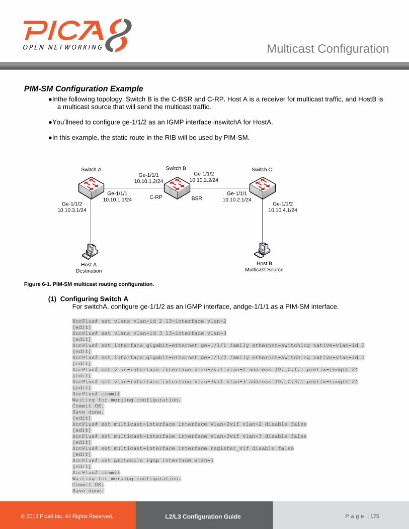
© 2012 Pica8 Inc. All © 2012 Pica8 Inc. All
Multicast Configuration
© 2013 Pica8 Inc. All Rights Reserved. L2/L3 Configuration Guide
P a g e | 175
PIM-SM Configuration Example
●Inthe following topology, Switch B is the C-BSR and C-RP. Host A is a receiver for multicast traffic, and HostB is a multicast source that will send the multicast traffic.
●You’llneed to configure ge-1/1/2 as an IGMP interface inswitchA for HostA. ●In this example, the static route in the RIB will be used by PIM-SM.
Host B
Multicast Source
Switch A
Ge-1/1/1
10.10.1.1/24
Host A
Destination
Switch B Switch CGe-1/1/1
10.10.1.2/24
Ge-1/1/2
10.10.2.2/24
Ge-1/1/1
10.10.2.1/24Ge-1/1/2
10.10.3.1/24
Ge-1/1/2
10.10.4.1/24
BSRC-RP
Figure 6-1. PIM-SM multicast routing configuration.
(1) Configuring Switch A For switchA, configure ge-1/1/2 as an IGMP interface, andge-1/1/1 as a PIM-SM interface. XorPlus# set vlans vlan-id 2 l3-interface vlan-2
[edit]
XorPlus# set vlans vlan-id 3 l3-interface vlan-3
[edit]
XorPlus# set interface gigabit-ethernet ge-1/1/1 family ethernet-switching native-vlan-id 2
[edit]
XorPlus# set interface gigabit-ethernet ge-1/1/2 family ethernet-switching native-vlan-id 3
[edit]
XorPlus# set vlan-interface interface vlan-2vif vlan-2 address 10.10.1.1 prefix-length 24
[edit]
XorPlus# set vlan-interface interface vlan-3vif vlan-3 address 10.10.3.1 prefix-length 24
[edit]
XorPlus# commit
Waiting for merging configuration.
Commit OK.
Save done.
[edit]
XorPlus# set multicast-interface interface vlan-2vif vlan-2 disable false
[edit]
XorPlus# set multicast-interface interface vlan-3vif vlan-3 disable false
[edit]
XorPlus# set multicast-interface interface register_vif disable false
[edit]
XorPlus# set protocols igmp interface vlan-3
[edit]
XorPlus# commit
Waiting for merging configuration.
Commit OK.
Save done.
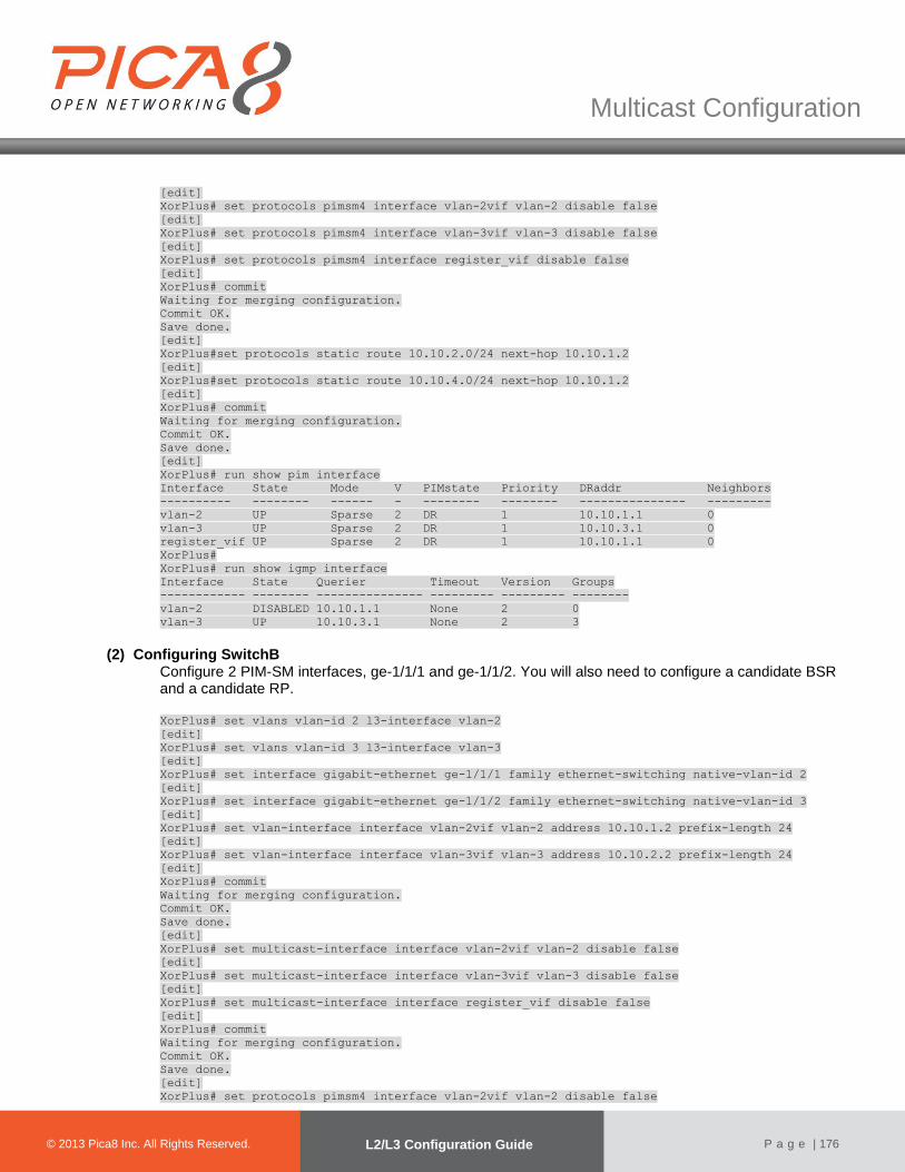
© 2012 Pica8 Inc. All © 2012 Pica8 Inc. All
Multicast Configuration
© 2013 Pica8 Inc. All Rights Reserved. L2/L3 Configuration Guide
P a g e | 176
[edit]
XorPlus# set protocols pimsm4 interface vlan-2vif vlan-2 disable false
[edit]
XorPlus# set protocols pimsm4 interface vlan-3vif vlan-3 disable false
[edit]
XorPlus# set protocols pimsm4 interface register_vif disable false
[edit]
XorPlus# commit
Waiting for merging configuration.
Commit OK.
Save done.
[edit]
XorPlus#set protocols static route 10.10.2.0/24 next-hop 10.10.1.2
[edit]
XorPlus#set protocols static route 10.10.4.0/24 next-hop 10.10.1.2
[edit]
XorPlus# commit
Waiting for merging configuration.
Commit OK.
Save done.
[edit]
XorPlus# run show pim interface
Interface State Mode V PIMstate Priority DRaddr Neighbors
---------- -------- ------ - -------- -------- --------------- ---------
vlan-2 UP Sparse 2 DR 1 10.10.1.1 0
vlan-3 UP Sparse 2 DR 1 10.10.3.1 0
register_vif UP Sparse 2 DR 1 10.10.1.1 0
XorPlus#
XorPlus# run show igmp interface
Interface State Querier Timeout Version Groups
------------ -------- --------------- --------- --------- --------
vlan-2 DISABLED 10.10.1.1 None 2 0
vlan-3 UP 10.10.3.1 None 2 3
(2) Configuring SwitchB
Configure 2 PIM-SM interfaces, ge-1/1/1 and ge-1/1/2. You will also need to configure a candidate BSR and a candidate RP. XorPlus# set vlans vlan-id 2 l3-interface vlan-2
[edit]
XorPlus# set vlans vlan-id 3 l3-interface vlan-3
[edit]
XorPlus# set interface gigabit-ethernet ge-1/1/1 family ethernet-switching native-vlan-id 2
[edit]
XorPlus# set interface gigabit-ethernet ge-1/1/2 family ethernet-switching native-vlan-id 3
[edit]
XorPlus# set vlan-interface interface vlan-2vif vlan-2 address 10.10.1.2 prefix-length 24
[edit]
XorPlus# set vlan-interface interface vlan-3vif vlan-3 address 10.10.2.2 prefix-length 24
[edit]
XorPlus# commit
Waiting for merging configuration.
Commit OK.
Save done.
[edit]
XorPlus# set multicast-interface interface vlan-2vif vlan-2 disable false
[edit]
XorPlus# set multicast-interface interface vlan-3vif vlan-3 disable false
[edit]
XorPlus# set multicast-interface interface register_vif disable false
[edit]
XorPlus# commit
Waiting for merging configuration.
Commit OK.
Save done.
[edit]
XorPlus# set protocols pimsm4 interface vlan-2vif vlan-2 disable false
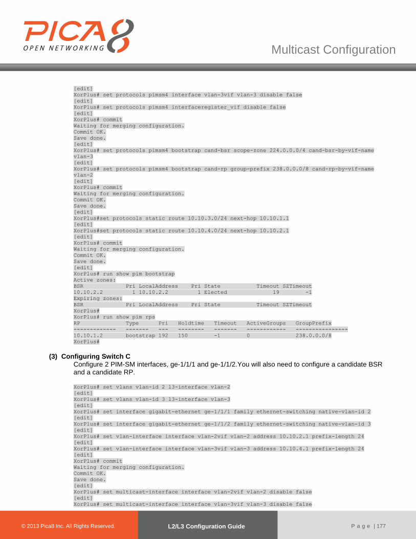
© 2012 Pica8 Inc. All © 2012 Pica8 Inc. All
Multicast Configuration
© 2013 Pica8 Inc. All Rights Reserved. L2/L3 Configuration Guide
P a g e | 177
[edit]
XorPlus# set protocols pimsm4 interface vlan-3vif vlan-3 disable false
[edit]
XorPlus# set protocols pimsm4 interfaceregister_vif disable false
[edit]
XorPlus# commit
Waiting for merging configuration.
Commit OK.
Save done.
[edit]
XorPlus# set protocols pimsm4 bootstrap cand-bsr scope-zone 224.0.0.0/4 cand-bsr-by-vif-name
vlan-3
[edit]
XorPlus# set protocols pimsm4 bootstrap cand-rp group-prefix 238.0.0.0/8 cand-rp-by-vif-name
vlan-2
[edit]
XorPlus# commit
Waiting for merging configuration.
Commit OK.
Save done.
[edit]
XorPlus#set protocols static route 10.10.3.0/24 next-hop 10.10.1.1
[edit]
XorPlus#set protocols static route 10.10.4.0/24 next-hop 10.10.2.1
[edit]
XorPlus# commit
Waiting for merging configuration.
Commit OK.
Save done.
[edit] XorPlus# run show pim bootstrap
Active zones:
BSR Pri LocalAddress Pri State Timeout SZTimeout
10.10.2.2 1 10.10.2.2 1 Elected 19 -1
Expiring zones:
BSR Pri LocalAddress Pri State Timeout SZTimeout
XorPlus#
XorPlus# run show pim rps
RP Type Pri Holdtime Timeout ActiveGroups GroupPrefix
------------- ------- --- -------- ------- ------------ ----------------
10.10.1.2 bootstrap 192 150 -1 0 238.0.0.0/8
XorPlus#
(3) Configuring Switch C
Configure 2 PIM-SM interfaces, ge-1/1/1 and ge-1/1/2.You will also need to configure a candidate BSR and a candidate RP. XorPlus# set vlans vlan-id 2 l3-interface vlan-2
[edit]
XorPlus# set vlans vlan-id 3 l3-interface vlan-3
[edit]
XorPlus# set interface gigabit-ethernet ge-1/1/1 family ethernet-switching native-vlan-id 2
[edit]
XorPlus# set interface gigabit-ethernet ge-1/1/2 family ethernet-switching native-vlan-id 3
[edit]
XorPlus# set vlan-interface interface vlan-2vif vlan-2 address 10.10.2.1 prefix-length 24
[edit]
XorPlus# set vlan-interface interface vlan-3vif vlan-3 address 10.10.4.1 prefix-length 24
[edit]
XorPlus# commit
Waiting for merging configuration.
Commit OK.
Save done.
[edit]
XorPlus# set multicast-interface interface vlan-2vif vlan-2 disable false
[edit]
XorPlus# set multicast-interface interface vlan-3vif vlan-3 disable false
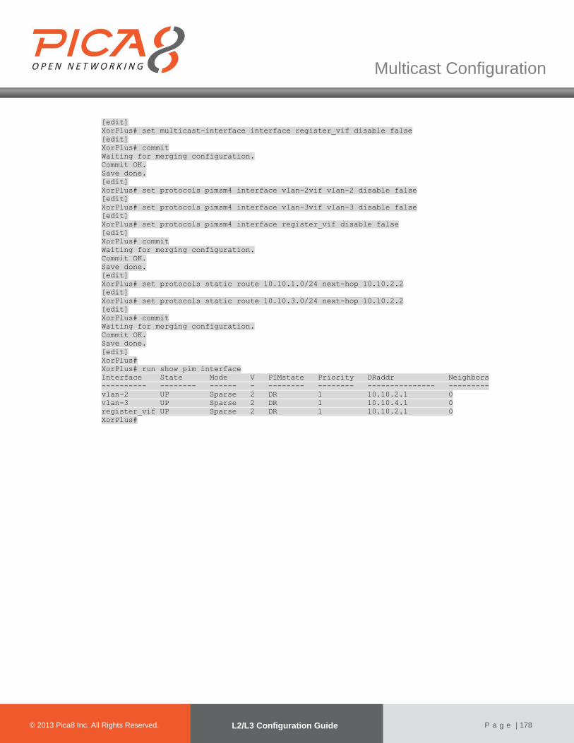
© 2012 Pica8 Inc. All © 2012 Pica8 Inc. All
Multicast Configuration
© 2013 Pica8 Inc. All Rights Reserved. L2/L3 Configuration Guide
P a g e | 178
[edit]
XorPlus# set multicast-interface interface register_vif disable false
[edit]
XorPlus# commit
Waiting for merging configuration.
Commit OK.
Save done.
[edit]
XorPlus# set protocols pimsm4 interface vlan-2vif vlan-2 disable false
[edit]
XorPlus# set protocols pimsm4 interface vlan-3vif vlan-3 disable false
[edit]
XorPlus# set protocols pimsm4 interface register_vif disable false
[edit]
XorPlus# commit
Waiting for merging configuration.
Commit OK.
Save done.
[edit]
XorPlus# set protocols static route 10.10.1.0/24 next-hop 10.10.2.2
[edit]
XorPlus# set protocols static route 10.10.3.0/24 next-hop 10.10.2.2
[edit]
XorPlus# commit
Waiting for merging configuration.
Commit OK.
Save done.
[edit]
XorPlus#
XorPlus# run show pim interface
Interface State Mode V PIMstate Priority DRaddr Neighbors
---------- -------- ------ - -------- -------- --------------- ---------
vlan-2 UP Sparse 2 DR 1 10.10.2.1 0
vlan-3 UP Sparse 2 DR 1 10.10.4.1 0
register_vif UP Sparse 2 DR 1 10.10.2.1 0
XorPlus#
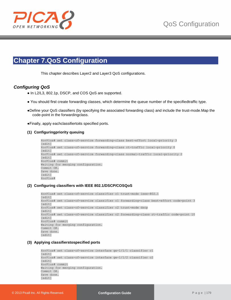
QoS Configuration
© 2012 Pica8 Inc. All © 2012 Pica8 Inc. All
© 2013 Pica8 Inc. All Rights Reserved. Configuration Guide
P a g e | 179
Chapter 7.QoS Configuration
This chapter describes Layer2 and Layer3 QoS configurations.
Configuring QoS
● In L2/L3, 802.1p, DSCP, and COS QoS are supported. ● You should first create forwarding classes, which determine the queue number of the specifiedtraffic type.
●Define your QoS classifiers (by specifying the associated forwarding class) and include the trust-mode.Map the
code-point in the forwardingclass.
●Finally, apply eachclassifiertoits specified ports.
(1) Configuringpriority queuing
XorPlus# set class-of-service forwarding-class best-effort local-priority 3
[edit]
XorPlus# set class-of-service forwarding-class rt-traffic local-priority 0
[edit]
XorPlus# set class-of-service forwarding-class normal-traffic local-priority 2
[edit]
XorPlus# commit
Waiting for merging configuration.
Commit OK.
Save done.
[edit]
XorPlus#
(2) Configuring classifiers with IEEE 802.1/DSCP/COSQoS
XorPlus# set class-of-service classifier c1 trust-mode ieee-802.1
[edit]
XorPlus# set class-of-service classifier c1 forwarding-class best-effort code-point 3
[edit]
XorPlus# set class-of-service classifier c2 trust-mode dscp
[edit]
XorPlus# set class-of-service classifier c2 forwarding-class rt-traffic code-point 10
[edit]
XorPlus# commit
Waiting for merging configuration.
Commit OK.
Save done.
[edit]
(3) Applying classifierstospecified ports
XorPlus# set class-of-service interface ge-1/1/1 classifier c1
[edit]
XorPlus# set class-of-service interface ge-1/1/2 classifier c2
[edit]
XorPlus# commit
Waiting for merging configuration.
Commit OK.
Save done.
[edit]

© 2012 Pica8 Inc. All © 2012 Pica8 Inc. All
QoS Configuration
© 2013 Pica8 Inc. All Rights Reserved. L2/L3 Configuration Guide
P a g e | 180
XorPlus
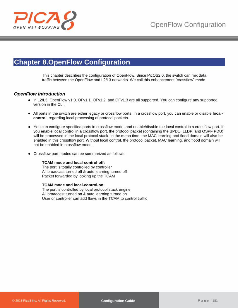
OpenFlow Configuration
© 2012 Pica8 Inc. All © 2012 Pica8 Inc. All
© 2013 Pica8 Inc. All Rights Reserved. Configuration Guide
P a g e | 181
Chapter 8.OpenFlow Configuration
This chapter describes the configuration of OpenFlow. Since PicOS2.0, the switch can mix data traffic between the OpenFlow and L2/L3 networks. We call this enhancement “crossflow” mode.
OpenFlow Introduction
● In L2/L3, OpenFlow v1.0, OFv1.1, OFv1.2, and OFv1.3 are all supported. You can configure any supported version in the CLI.
● All ports in the switch are either legacy or crossflow ports. In a crossflow port, you can enable or disable local-
control, regarding local processing of protocol packets.
● You can configure specified ports in crossflow mode, and enable/disable the local control in a crossflow port. If you enable local control in a crossflow port, the protocol packet (containing the BPDU, LLDP, and OSPF PDU) will be processed in the local protocol stack. In the mean time, the MAC learning and flood domain will also be enabled in this crossflow port. Without local control, the protocol packet, MAC learning, and flood domain will not be enabled in crossflow mode.
● Crossflow port modes can be summarized as follows:
TCAM mode and local-control-off: The port is totally controlled by controller All broadcast turned off & auto learning turned off Packet forwarded by looking up the TCAM TCAM mode and local-control-on: The port is controlled by local protocol stack engine All broadcast turned on & auto learning turned on User or controller can add flows in the TCAM to control traffic
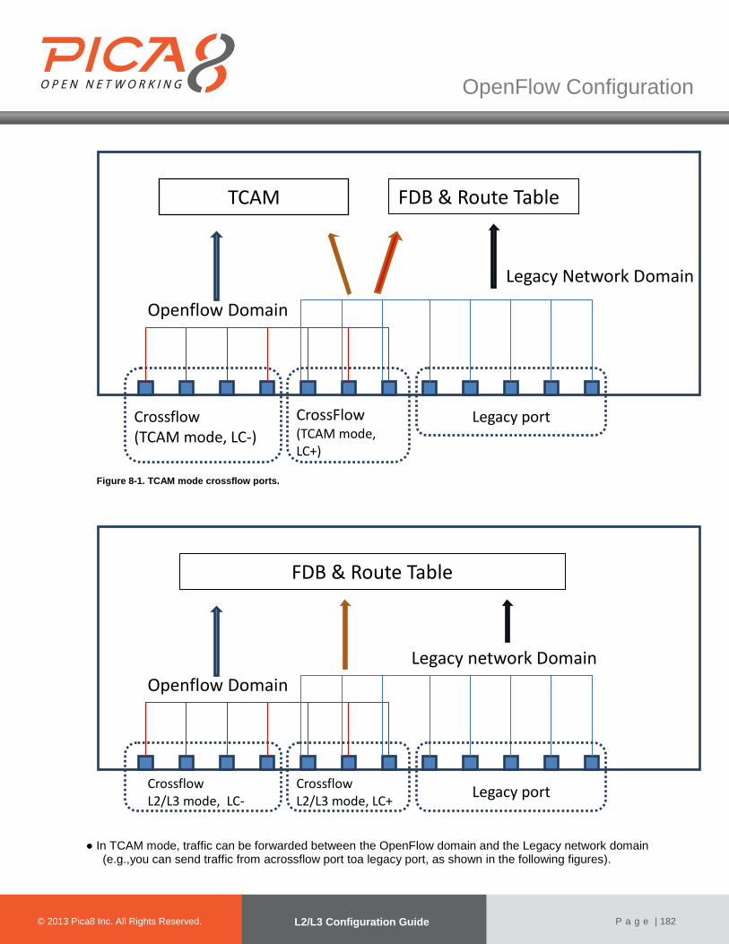
© 2012 Pica8 Inc. All © 2012 Pica8 Inc. All
OpenFlow Configuration
© 2013 Pica8 Inc. All Rights Reserved. L2/L3 Configuration Guide
P a g e | 182
Figure 8-1. TCAM mode crossflow ports.
● In TCAM mode, traffic can be forwarded between the OpenFlow domain and the Legacy network domain
(e.g.,you can send traffic from acrossflow port toa legacy port, as shown in the following figures).
Openflow Domain
Legacy network Domain
FDB & Route Table
Crossflow L2/L3 mode, LC-
Crossflow L2/L3 mode, LC+
Legacy port
Openflow Domain
Legacy Network Domain
FDB & Route Table TCAM
Crossflow (TCAM mode, LC-)
CrossFlow (TCAM mode, LC+)
Legacy port

© 2012 Pica8 Inc. All © 2012 Pica8 Inc. All
OpenFlow Configuration
© 2013 Pica8 Inc. All Rights Reserved. L2/L3 Configuration Guide
P a g e | 183
Figure 8-3. TCAM mode traffic between crossflow ports.
Openflow Domain
Legacy network Domain
FDB & Route Table TCAM
Traffic Traffic
Openflow Domain
Legacy network Domain
FDB & Route Table TCAM
Traffic Traffic
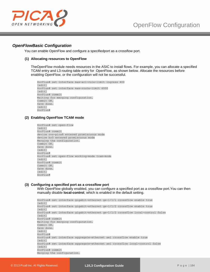
© 2012 Pica8 Inc. All © 2012 Pica8 Inc. All
OpenFlow Configuration
© 2013 Pica8 Inc. All Rights Reserved. L2/L3 Configuration Guide
P a g e | 184
OpenFlowBasic Configuration
You can enable OpenFlow and configure a specifiedport as a crossflow port. (1) Allocating resources to OpenFlow
TheOpenFlow module needs resources in the ASIC to install flows. For example, you can allocate a specified TCAM entry and L3 routing table entry for OpenFlow, as shown below. Allocate the resources before enabling OpenFlow, or the configuration will not be successful.
XorPlus# set interface max-acl-rule-limit ingress 400
[edit]
XorPlus# set interface max-route-limit 6000
[edit]
XorPlus# commit
Waiting for merging configuration.
Commit OK.
Save done.
[edit]
XorPlus#
(2) Enabling OpenFlow TCAM mode
XorPlus# set open-flow
[edit]
XorPlus# commit
device ovs-pica8 entered promiscuous mode
device br0 entered promiscuous mode
Merging the configuration.
Commit OK.
Save done.
[edit]
XorPlus#
XorPlus# set open-flow working-mode tcam-mode
[edit]
XorPlus# commit
Commit OK.
Save done.
[edit]
XorPlus#
(3) Configuring a specified port as a crossflow port With OpenFlow globally enabled, you can configure a specified port as a crossflow port.You can then manually disable local-control, which is enabled in the default setting.
XorPlus# set interface gigabit-ethernet ge-1/1/1 crossflow enable true
[edit]
XorPlus# set interface gigabit-ethernet ge-1/1/2 crossflow enable true
[edit]
XorPlus# set interface gigabit-ethernet ge-1/1/2 crossflow local-control false
[edit]
XorPlus# commit
Waiting for merging configuration.
Commit OK.
Save done.
[edit]
XorPlus#
XorPlus# set interface aggregate-ethernet ae1 crossflow enable true
[edit]
XorPlus# set interface aggregate-ethernet ae1 crossflow local-control false
[edit]
XorPlus# commit
Merging the configuration.
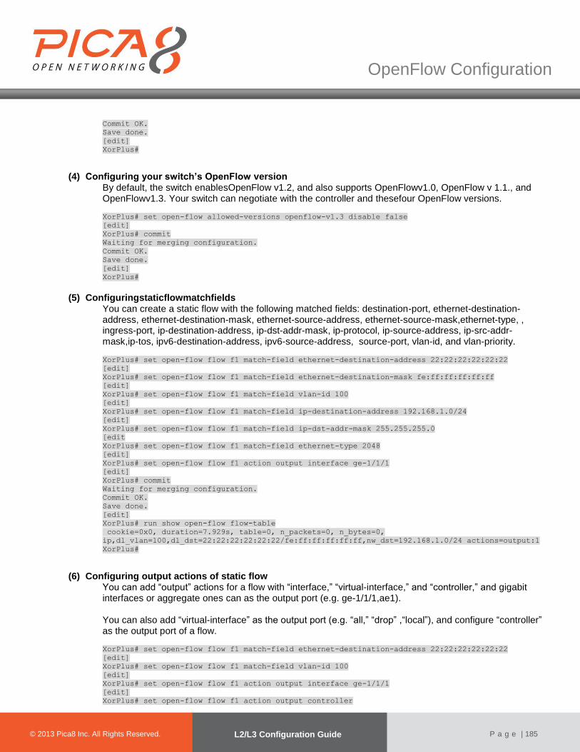
© 2012 Pica8 Inc. All © 2012 Pica8 Inc. All
OpenFlow Configuration
© 2013 Pica8 Inc. All Rights Reserved. L2/L3 Configuration Guide
P a g e | 185
Commit OK.
Save done.
[edit]
XorPlus#
(4) Configuring your switch’s OpenFlow version By default, the switch enablesOpenFlow v1.2, and also supports OpenFlowv1.0, OpenFlow v 1.1., and OpenFlowv1.3. Your switch can negotiate with the controller and thesefour OpenFlow versions.
XorPlus# set open-flow allowed-versions openflow-v1.3 disable false
[edit]
XorPlus# commit
Waiting for merging configuration.
Commit OK.
Save done.
[edit]
XorPlus#
(5) Configuringstaticflowmatchfields
You can create a static flow with the following matched fields: destination-port, ethernet-destination-address, ethernet-destination-mask, ethernet-source-address, ethernet-source-mask,ethernet-type, , ingress-port, ip-destination-address, ip-dst-addr-mask, ip-protocol, ip-source-address, ip-src-addr-mask,ip-tos, ipv6-destination-address, ipv6-source-address, source-port, vlan-id, and vlan-priority.
XorPlus# set open-flow flow f1 match-field ethernet-destination-address 22:22:22:22:22:22
[edit]
XorPlus# set open-flow flow f1 match-field ethernet-destination-mask fe:ff:ff:ff:ff:ff
[edit]
XorPlus# set open-flow flow f1 match-field vlan-id 100
[edit]
XorPlus# set open-flow flow f1 match-field ip-destination-address 192.168.1.0/24
[edit]
XorPlus# set open-flow flow f1 match-field ip-dst-addr-mask 255.255.255.0
[edit
XorPlus# set open-flow flow f1 match-field ethernet-type 2048
[edit]
XorPlus# set open-flow flow f1 action output interface ge-1/1/1
[edit]
XorPlus# commit
Waiting for merging configuration.
Commit OK.
Save done.
[edit]
XorPlus# run show open-flow flow-table
cookie=0x0, duration=7.929s, table=0, n_packets=0, n_bytes=0,
ip,dl_vlan=100,dl_dst=22:22:22:22:22:22/fe:ff:ff:ff:ff:ff,nw_dst=192.168.1.0/24 actions=output:1
XorPlus#
(6) Configuring output actions of static flow You can add “output” actions for a flow with “interface,” “virtual-interface,” and “controller,” and gigabit interfaces or aggregate ones can as the output port (e.g. ge-1/1/1,ae1). You can also add “virtual-interface” as the output port (e.g. “all,” “drop” ,“local”), and configure “controller” as the output port of a flow.
XorPlus# set open-flow flow f1 match-field ethernet-destination-address 22:22:22:22:22:22
[edit]
XorPlus# set open-flow flow f1 match-field vlan-id 100
[edit]
XorPlus# set open-flow flow f1 action output interface ge-1/1/1
[edit]
XorPlus# set open-flow flow f1 action output controller
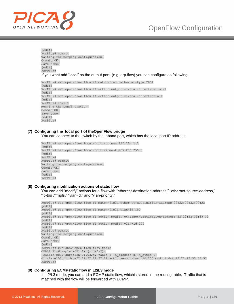
© 2012 Pica8 Inc. All © 2012 Pica8 Inc. All
OpenFlow Configuration
© 2013 Pica8 Inc. All Rights Reserved. L2/L3 Configuration Guide
P a g e | 186
[edit]
XorPlus# commit
Waiting for merging configuration.
Commit OK.
Save done.
[edit]
XorPlus#
If you want add “local” as the output port, (e.g. arp flow) you can configure as following.
XorPlus# set open-flow flow f1 match-field ethernet-type 2054
[edit]
XorPlus# set open-flow flow f1 action output virtual-interface local
[edit]
XorPlus# set open-flow flow f1 action output virtual-interface all
[edit]
XorPlus# commit
Merging the configuration.
Commit OK.
Save done.
[edit]
XorPlus#
(7) Configuring the local port of theOpenFlow bridge You can connect to the switch by the inband port, which has the local port IP address.
XorPlus# set open-flow local-port address 192.168.1.1
[edit]
XorPlus# set open-flow local-port netmask 255.255.255.0
[edit]
XorPlus#
XorPlus# commit
Waiting for merging configuration.
Commit OK.
Save done.
[edit]
XorPlus#
(8) Configuring modification actions of static flow
You can add “modify” actions for a flow with “ethernet-destination-address,” “ethernet-source-address,” “ip-tos ,““mpls,” “vlan-id,” and “vlan-priority.”
XorPlus# set open-flow flow f1 match-field ethernet-destination-address 22:22:22:22:22:22
[edit]
XorPlus# set open-flow flow f1 match-field vlan-id 100
[edit]
XorPlus# set open-flow flow f1 action modify ethernet-destination-address 22:22:22:33:33:33
[edit]
XorPlus# set open-flow flow f1 action modify vlan-id 200
[edit]
XorPlus# commit
Waiting for merging configuration.
Commit OK.
Save done.
[edit]
XorPlus# run show open-flow flow-table
OFPST_FLOW reply (OF1.2) (xid=0x2):
cookie=0x0, duration=11.032s, table=0, n_packets=0, n_bytes=0,
dl_vlan=100,dl_dst=22:22:22:22:22:22 actions=mod_vlan_vid:200,mod_dl_dst:22:22:22:33:33:33
XorPlus#
(9) Configuring ECMPstatic flow in L2/L3 mode
In L2/L3 mode, you can add a ECMP static flow, whichis stored in the routing table. Traffic that is matched with the flow will be forwarded with ECMP.
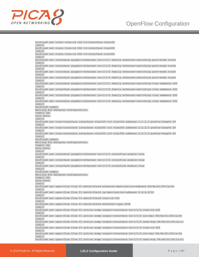
© 2012 Pica8 Inc. All © 2012 Pica8 Inc. All
OpenFlow Configuration
© 2013 Pica8 Inc. All Rights Reserved. L2/L3 Configuration Guide
P a g e | 187
XorPlus# set vlans vlan-id 100 l3-interface vlan100
[edit]
XorPlus# set vlans vlan-id 200 l3-interface vlan200
[edit]
XorPlus# set vlans vlan-id 300 l3-interface vlan300
[edit]
XorPlus# set interface gigabit-ethernet te-1/1/1 family ethernet-switching port-mode trunk
[edit]
XorPlus# set interface gigabit-ethernet te-1/1/2 family ethernet-switching port-mode trunk
[edit]
XorPlus# set interface gigabit-ethernet te-1/1/3 family ethernet-switching port-mode trunk
[edit]
XorPlus# set interface gigabit-ethernet te-1/1/4 family ethernet-switching port-mode trunk
[edit]
XorPlus# set interface gigabit-ethernet te-1/1/1 family ethernet-switching vlan members 100
[edit]
XorPlus# set interface gigabit-ethernet te-1/1/2 family ethernet-switching vlan members 100
[edit]
XorPlus# set interface gigabit-ethernet te-1/1/3 family ethernet-switching vlan members 200
[edit]
XorPlus# set interface gigabit-ethernet te-1/1/4 family ethernet-switching vlan members 300
[edit]
XorPlus# commit
Waiting for merging configuration.
Commit OK.
Save done.
[edit]
XorPlus# set vlan-interface interface vlan100 vif vlan100 address 1.1.1.1 prefix-length 24
[edit]
XorPlus# set vlan-interface interface vlan200 vif vlan200 address 2.2.2.2 prefix-length 24
[edit]
XorPlus# set vlan-interface interface vlan300 vif vlan300 address 3.3.3.3 prefix-length 24
[edit]
XorPlus# commit
Waiting for merging configuration.
Commit OK.
Save done.
[edit]
XorPlus# set interface gigabit-ethernet te-1/1/1 crossflow enable true
[edit]
XorPlus# set interface gigabit-ethernet te-1/1/2 crossflow enable true
[edit]
XorPlus# set interface gigabit-ethernet te-1/1/3 crossflow enable true
[edit]
XorPlus# commit
Waiting for merging configuration.
Commit OK.
Save done.
[edit]
XorPlus# set open-flow flow f1 match-field ethernet-destination-address 08:9e:01:39:1a:fe
[edit]
XorPlus# set open-flow flow f1 match-field ip-destination-address 4.4.4.0/24
[edit]
XorPlus# set open-flow flow f1 match-field vlan-id 100
[edit]
XorPlus# set open-flow flow f1 match-field ethernet-type 2048
[edit]
XorPlus# set open-flow flow f1 action ecmp output-interface te-1/1/2 vlan-id 200
[edit]
XorPlus# set open-flow flow f1 action ecmp output-interface te-1/1/2 src-mac 08:9e:01:39:1a:fe
[edit]
XorPlus# set open-flow flow f1 action ecmp output-interface te-1/1/2 next-hop 08:9e:01:39:1a:11
[edit]
XorPlus# set open-flow flow f1 action ecmp output-interface te-1/1/3 vlan-id 300
[edit]
XorPlus# set open-flow flow f1 action ecmp output-interface te-1/1/3 src-mac 08:9e:01:39:1a:fe
[edit]
XorPlus# set open-flow flow f1 action ecmp output-interface te-1/1/3 next-hop 08:9e:01:39:1a:22

© 2012 Pica8 Inc. All © 2012 Pica8 Inc. All
OpenFlow Configuration
© 2013 Pica8 Inc. All Rights Reserved. L2/L3 Configuration Guide
P a g e | 188
[edit]
XorPlus# commit
Waiting for merging configuration.
Commit OK.
Save done.
[edit]
XorPlus# run show open-flow flow-table layer-3
FlowID Destination NetMask NextHopMac Output
------ --------------- --------------- ----------------- ---------
1 4.4.4.0 255.255.255.0 08:9e:01:39:1a:11 te-1/1/2
1 4.4.4.0 255.255.255.0 08:9e:01:39:1a:22 te-1/1/3
XorPlus#
(10) Configuring the switch’s working mode You can configure the switch to work in TCAMmode or L2/L3 mode. In TCAMmode, all flows will be installed in theTCAM table. In L2/L3mode, all flows will be installed in the routing and FDB tables.
XorPlus# set open-flow working-mode tcam-mode
[edit]
XorPlus# commit
Waiting for merging configuration.
Commit OK.
Save done.
[edit]
XorPlus#
(11) Configuring your OpenFlow controller
You can configure multiple controllers for the OpenFlow bridge (only one of them will be the active controller).
XorPlus# set open-flow controller contr-serv address 192.168.1.100
[edit]
XorPlus# set open-flow controller contr-serv port 6633
[edit]
XorPlus# set open-flow controller contr-serv protocol tcp
[edit]
XorPlus# commit
Waiting for merging configuration.
Commit OK.
Save done.
[edit]
Group table Configuration
In PicOS2.1, supports goup table. Because of the ASIC limitation, not all buckets in a group table will be installed to ASIC for a flow. The system will install buckets at most as possible to ASIC. User can create group tables with type all/indirect/select/fast-failover. You can add “modify” actions for a bucket with “ethernet-destination-address,” “ethernet-source-address,” “ip-tos ,“ “mpls,” “vlan-id,” and “vlan-priority.”
(1) Create group table with one bucket
user can create a group table and a flow whose action is a group table.
XorPlus# set open-flow groups group-id 1 type all
[edit]
XorPlus# set open-flow groups group-id 1 bucket-id 1 action modify eth-dst-address
22:22:22:22:22:22
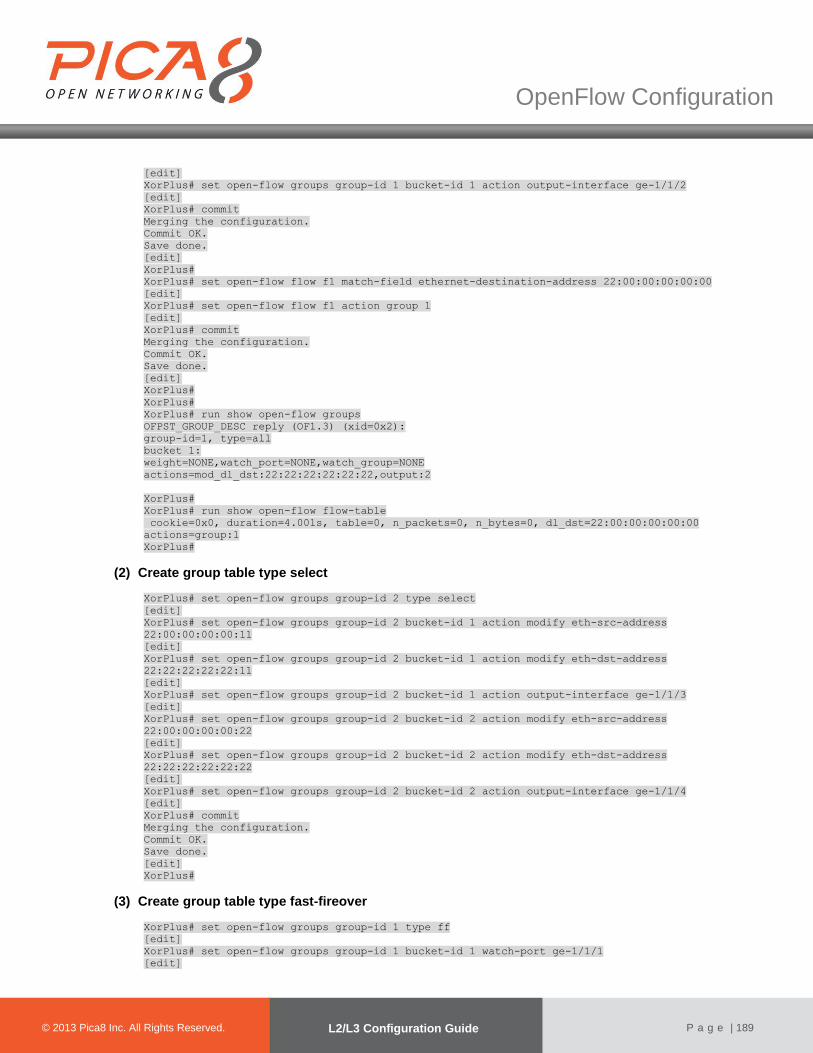
© 2012 Pica8 Inc. All © 2012 Pica8 Inc. All
OpenFlow Configuration
© 2013 Pica8 Inc. All Rights Reserved. L2/L3 Configuration Guide
P a g e | 189
[edit]
XorPlus# set open-flow groups group-id 1 bucket-id 1 action output-interface ge-1/1/2
[edit]
XorPlus# commit
Merging the configuration.
Commit OK.
Save done.
[edit]
XorPlus#
XorPlus# set open-flow flow f1 match-field ethernet-destination-address 22:00:00:00:00:00
[edit]
XorPlus# set open-flow flow f1 action group 1
[edit]
XorPlus# commit
Merging the configuration.
Commit OK.
Save done.
[edit]
XorPlus#
XorPlus#
XorPlus# run show open-flow groups
OFPST_GROUP_DESC reply (OF1.3) (xid=0x2):
group-id=1, type=all
bucket 1:
weight=NONE,watch_port=NONE,watch_group=NONE
actions=mod_dl_dst:22:22:22:22:22:22,output:2
XorPlus#
XorPlus# run show open-flow flow-table
cookie=0x0, duration=4.001s, table=0, n_packets=0, n_bytes=0, dl_dst=22:00:00:00:00:00
actions=group:1
XorPlus#
(2) Create group table type select
XorPlus# set open-flow groups group-id 2 type select
[edit]
XorPlus# set open-flow groups group-id 2 bucket-id 1 action modify eth-src-address
22:00:00:00:00:11
[edit]
XorPlus# set open-flow groups group-id 2 bucket-id 1 action modify eth-dst-address
22:22:22:22:22:11
[edit]
XorPlus# set open-flow groups group-id 2 bucket-id 1 action output-interface ge-1/1/3
[edit]
XorPlus# set open-flow groups group-id 2 bucket-id 2 action modify eth-src-address
22:00:00:00:00:22
[edit]
XorPlus# set open-flow groups group-id 2 bucket-id 2 action modify eth-dst-address
22:22:22:22:22:22
[edit]
XorPlus# set open-flow groups group-id 2 bucket-id 2 action output-interface ge-1/1/4
[edit]
XorPlus# commit
Merging the configuration.
Commit OK.
Save done.
[edit]
XorPlus#
(3) Create group table type fast-fireover
XorPlus# set open-flow groups group-id 1 type ff
[edit]
XorPlus# set open-flow groups group-id 1 bucket-id 1 watch-port ge-1/1/1
[edit]
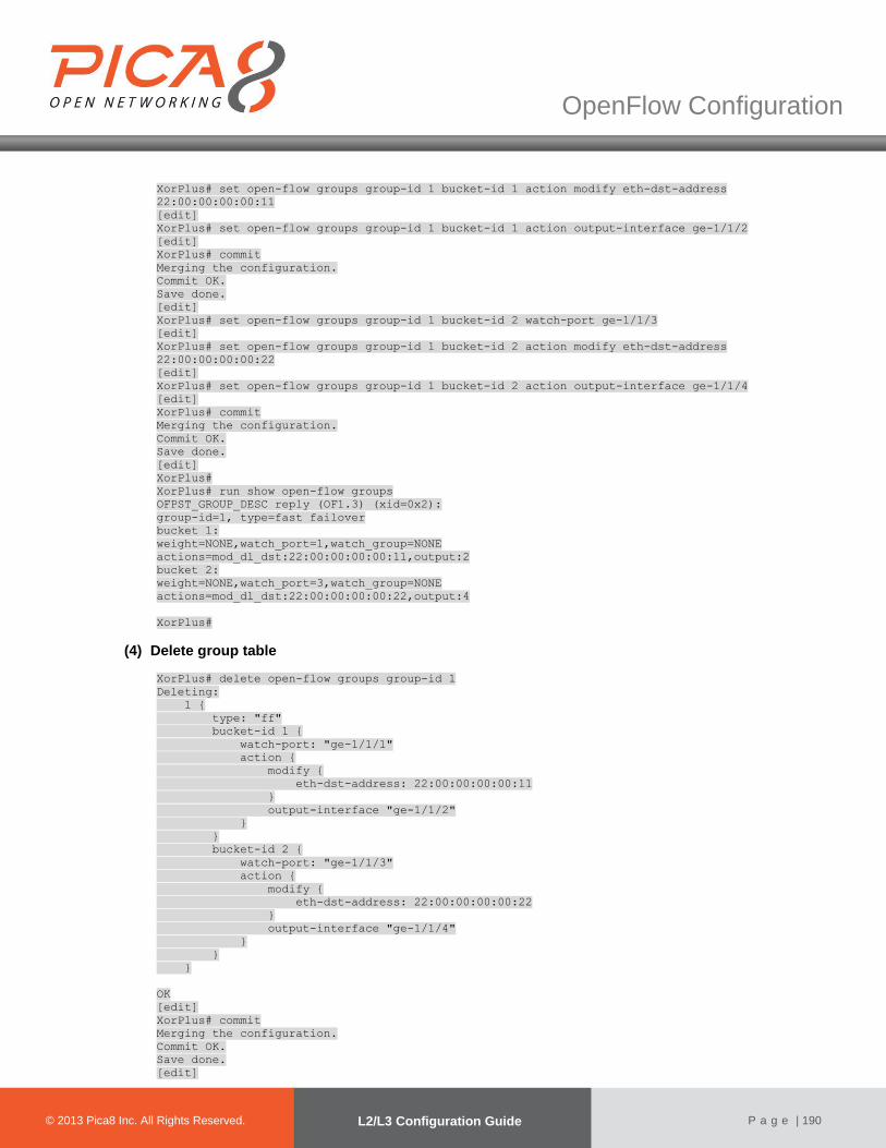
© 2012 Pica8 Inc. All © 2012 Pica8 Inc. All
OpenFlow Configuration
© 2013 Pica8 Inc. All Rights Reserved. L2/L3 Configuration Guide
P a g e | 190
XorPlus# set open-flow groups group-id 1 bucket-id 1 action modify eth-dst-address
22:00:00:00:00:11
[edit]
XorPlus# set open-flow groups group-id 1 bucket-id 1 action output-interface ge-1/1/2
[edit]
XorPlus# commit
Merging the configuration.
Commit OK.
Save done.
[edit]
XorPlus# set open-flow groups group-id 1 bucket-id 2 watch-port ge-1/1/3
[edit]
XorPlus# set open-flow groups group-id 1 bucket-id 2 action modify eth-dst-address
22:00:00:00:00:22
[edit]
XorPlus# set open-flow groups group-id 1 bucket-id 2 action output-interface ge-1/1/4
[edit]
XorPlus# commit
Merging the configuration.
Commit OK.
Save done.
[edit]
XorPlus#
XorPlus# run show open-flow groups
OFPST_GROUP_DESC reply (OF1.3) (xid=0x2):
group-id=1, type=fast failover
bucket 1:
weight=NONE,watch_port=1,watch_group=NONE
actions=mod_dl_dst:22:00:00:00:00:11,output:2
bucket 2:
weight=NONE,watch_port=3,watch_group=NONE
actions=mod_dl_dst:22:00:00:00:00:22,output:4
XorPlus#
(4) Delete group table
XorPlus# delete open-flow groups group-id 1
Deleting:
1 {
type: "ff"
bucket-id 1 {
watch-port: "ge-1/1/1"
action {
modify {
eth-dst-address: 22:00:00:00:00:11
}
output-interface "ge-1/1/2"
}
}
bucket-id 2 {
watch-port: "ge-1/1/3"
action {
modify {
eth-dst-address: 22:00:00:00:00:22
}
output-interface "ge-1/1/4"
}
}
}
OK
[edit]
XorPlus# commit
Merging the configuration.
Commit OK.
Save done.
[edit]
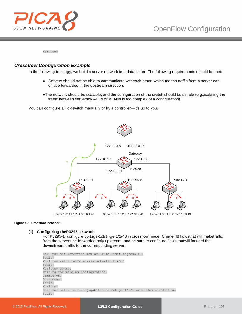
© 2012 Pica8 Inc. All © 2012 Pica8 Inc. All
OpenFlow Configuration
© 2013 Pica8 Inc. All Rights Reserved. L2/L3 Configuration Guide
P a g e | 191
XorPlus#
Crossflow Configuration Example
In the following topology, we build a server network in a datacenter. The following requirements should be met:
● Servers should not be able to communicate witheach other, which means traffic from a server can onlybe forwarded in the upstream direction.
●The network should be scalable, and the configuration of the switch should be simple (e.g.,isolating the
traffic between serversby ACLs or VLANs is too complex of a configuration).
You can configure a ToRswitch manually or by a controller—it’s up to you.
172.16.1.1
Server:172.16.1.2~172.16.1.49
172.16.3.1
172.16.2.1
172.16.4.x
P-3920
P-3295-1 P-3295-2 P-3295-3
OSPF/BGP
Server:172.16.2.2~172.16.2.49 Server:172.16.3.2~172.16.3.49
X XX X
V
Gateway
Figure 8-5. Crossflow network.
(1) Configuring theP3295-1 switch For P3295-1, configure portsge-1/1/1~ge-1/1/48 in crossflow mode. Create 48 flowsthat will maketraffic from the servers be forwarded only upstream, and be sure to configure flows thatwill forward the downstream traffic to the corresponding server. XorPlus# set interface max-acl-rule-limit ingress 400
[edit]
XorPlus# set interface max-route-limit 6000
[edit]
XorPlus# commit
Waiting for merging configuration.
Commit OK.
Save done.
[edit]
XorPlus#
XorPlus# set interface gigabit-ethernet ge-1/1/1 crossflow enable true
[edit]
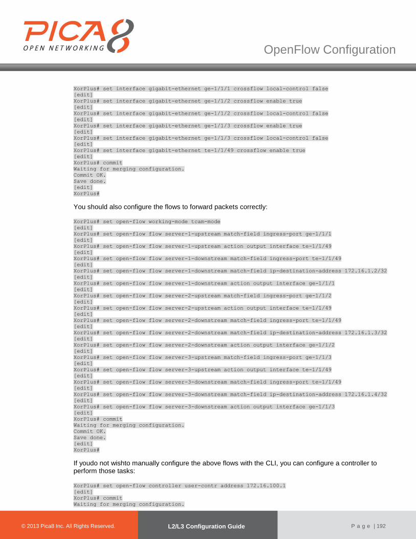
© 2012 Pica8 Inc. All © 2012 Pica8 Inc. All
OpenFlow Configuration
© 2013 Pica8 Inc. All Rights Reserved. L2/L3 Configuration Guide
P a g e | 192
XorPlus# set interface gigabit-ethernet ge-1/1/1 crossflow local-control false
[edit]
XorPlus# set interface gigabit-ethernet ge-1/1/2 crossflow enable true
[edit]
XorPlus# set interface gigabit-ethernet ge-1/1/2 crossflow local-control false
[edit]
XorPlus# set interface gigabit-ethernet ge-1/1/3 crossflow enable true
[edit]
XorPlus# set interface gigabit-ethernet ge-1/1/3 crossflow local-control false
[edit]
XorPlus# set interface gigabit-ethernet te-1/1/49 crossflow enable true
[edit]
XorPlus# commit
Waiting for merging configuration.
Commit OK.
Save done.
[edit]
XorPlus#
You should also configure the flows to forward packets correctly: XorPlus# set open-flow working-mode tcam-mode
[edit]
XorPlus# set open-flow flow server-1-upstream match-field ingress-port ge-1/1/1
[edit]
XorPlus# set open-flow flow server-1-upstream action output interface te-1/1/49
[edit]
XorPlus# set open-flow flow server-1-downstream match-field ingress-port te-1/1/49
[edit]
XorPlus# set open-flow flow server-1-downstream match-field ip-destination-address 172.16.1.2/32
[edit]
XorPlus# set open-flow flow server-1-downstream action output interface ge-1/1/1
[edit]
XorPlus# set open-flow flow server-2-upstream match-field ingress-port ge-1/1/2
[edit]
XorPlus# set open-flow flow server-2-upstream action output interface te-1/1/49
[edit]
XorPlus# set open-flow flow server-2-downstream match-field ingress-port te-1/1/49
[edit]
XorPlus# set open-flow flow server-2-downstream match-field ip-destination-address 172.16.1.3/32
[edit]
XorPlus# set open-flow flow server-2-downstream action output interface ge-1/1/2
[edit]
XorPlus# set open-flow flow server-3-upstream match-field ingress-port ge-1/1/3
[edit]
XorPlus# set open-flow flow server-3-upstream action output interface te-1/1/49
[edit]
XorPlus# set open-flow flow server-3-downstream match-field ingress-port te-1/1/49
[edit]
XorPlus# set open-flow flow server-3-downstream match-field ip-destination-address 172.16.1.4/32
[edit]
XorPlus# set open-flow flow server-3-downstream action output interface ge-1/1/3
[edit]
XorPlus# commit
Waiting for merging configuration.
Commit OK.
Save done.
[edit]
XorPlus#
If youdo not wishto manually configure the above flows with the CLI, you can configure a controller to perform those tasks: XorPlus# set open-flow controller user-contr address 172.16.100.1
[edit]
XorPlus# commit
Waiting for merging configuration.
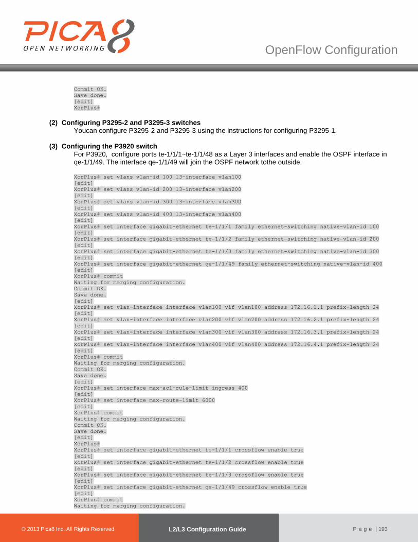
© 2012 Pica8 Inc. All © 2012 Pica8 Inc. All
OpenFlow Configuration
© 2013 Pica8 Inc. All Rights Reserved. L2/L3 Configuration Guide
P a g e | 193
Commit OK.
Save done.
[edit]
XorPlus#
(2) Configuring P3295-2 and P3295-3 switches
Youcan configure P3295-2 and P3295-3 using the instructions for configuring P3295-1.
(3) Configuring the P3920 switch For P3920, configure ports te-1/1/1~te-1/1/48 as a Layer 3 interfaces and enable the OSPF interface in qe-1/1/49. The interface qe-1/1/49 will join the OSPF network tothe outside. XorPlus# set vlans vlan-id 100 l3-interface vlan100
[edit]
XorPlus# set vlans vlan-id 200 l3-interface vlan200
[edit]
XorPlus# set vlans vlan-id 300 l3-interface vlan300
[edit]
XorPlus# set vlans vlan-id 400 l3-interface vlan400
[edit]
XorPlus# set interface gigabit-ethernet te-1/1/1 family ethernet-switching native-vlan-id 100
[edit]
XorPlus# set interface gigabit-ethernet te-1/1/2 family ethernet-switching native-vlan-id 200
[edit]
XorPlus# set interface gigabit-ethernet te-1/1/3 family ethernet-switching native-vlan-id 300
[edit]
XorPlus# set interface gigabit-ethernet qe-1/1/49 family ethernet-switching native-vlan-id 400
[edit]
XorPlus# commit
Waiting for merging configuration.
Commit OK.
Save done.
[edit]
XorPlus# set vlan-interface interface vlan100 vif vlan100 address 172.16.1.1 prefix-length 24
[edit]
XorPlus# set vlan-interface interface vlan200 vif vlan200 address 172.16.2.1 prefix-length 24
[edit]
XorPlus# set vlan-interface interface vlan300 vif vlan300 address 172.16.3.1 prefix-length 24
[edit]
XorPlus# set vlan-interface interface vlan400 vif vlan400 address 172.16.4.1 prefix-length 24
[edit]
XorPlus# commit
Waiting for merging configuration.
Commit OK.
Save done.
[edit]
XorPlus# set interface max-acl-rule-limit ingress 400
[edit]
XorPlus# set interface max-route-limit 6000
[edit]
XorPlus# commit
Waiting for merging configuration.
Commit OK.
Save done.
[edit]
XorPlus#
XorPlus# set interface gigabit-ethernet te-1/1/1 crossflow enable true
[edit]
XorPlus# set interface gigabit-ethernet te-1/1/2 crossflow enable true
[edit]
XorPlus# set interface gigabit-ethernet te-1/1/3 crossflow enable true
[edit]
XorPlus# set interface gigabit-ethernet qe-1/1/49 crossflow enable true
[edit]
XorPlus# commit
Waiting for merging configuration.
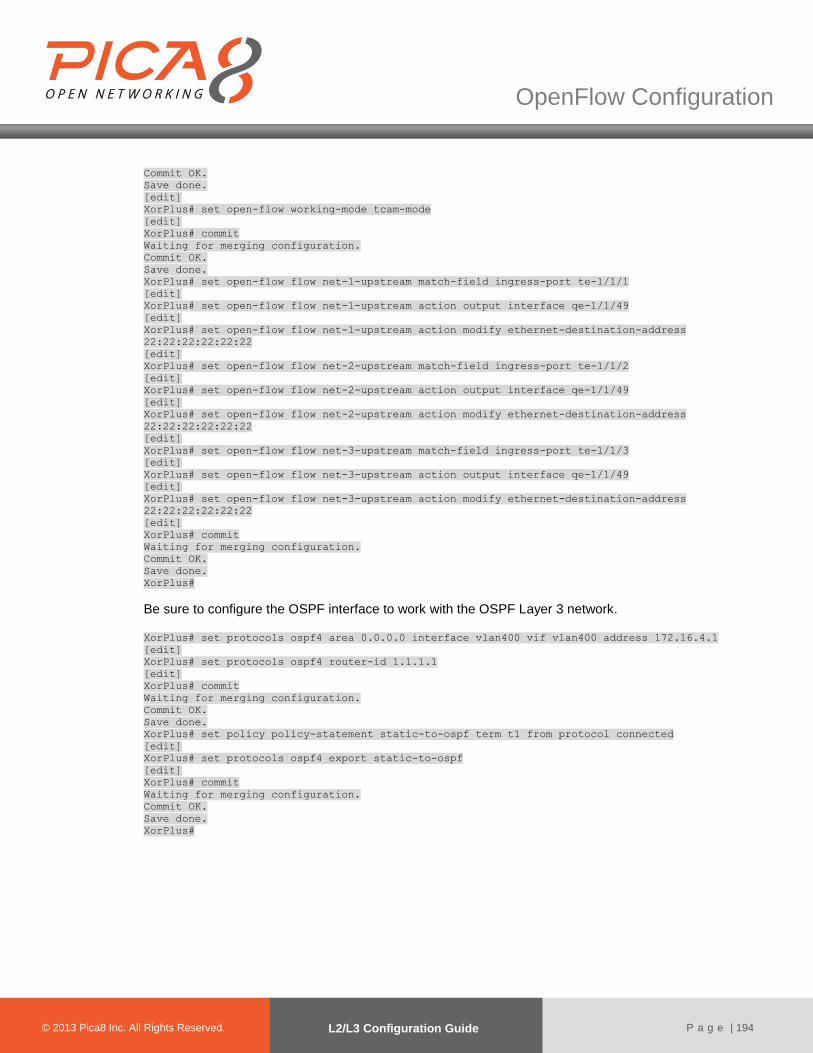
© 2012 Pica8 Inc. All © 2012 Pica8 Inc. All
OpenFlow Configuration
© 2013 Pica8 Inc. All Rights Reserved. L2/L3 Configuration Guide
P a g e | 194
Commit OK.
Save done.
[edit]
XorPlus# set open-flow working-mode tcam-mode
[edit]
XorPlus# commit
Waiting for merging configuration.
Commit OK.
Save done.
XorPlus# set open-flow flow net-1-upstream match-field ingress-port te-1/1/1
[edit]
XorPlus# set open-flow flow net-1-upstream action output interface qe-1/1/49
[edit]
XorPlus# set open-flow flow net-1-upstream action modify ethernet-destination-address
22:22:22:22:22:22
[edit]
XorPlus# set open-flow flow net-2-upstream match-field ingress-port te-1/1/2
[edit]
XorPlus# set open-flow flow net-2-upstream action output interface qe-1/1/49
[edit]
XorPlus# set open-flow flow net-2-upstream action modify ethernet-destination-address
22:22:22:22:22:22
[edit]
XorPlus# set open-flow flow net-3-upstream match-field ingress-port te-1/1/3
[edit]
XorPlus# set open-flow flow net-3-upstream action output interface qe-1/1/49
[edit]
XorPlus# set open-flow flow net-3-upstream action modify ethernet-destination-address
22:22:22:22:22:22
[edit]
XorPlus# commit
Waiting for merging configuration.
Commit OK.
Save done.
XorPlus#
Be sure to configure the OSPF interface to work with the OSPF Layer 3 network. XorPlus# set protocols ospf4 area 0.0.0.0 interface vlan400 vif vlan400 address 172.16.4.1
[edit]
XorPlus# set protocols ospf4 router-id 1.1.1.1
[edit]
XorPlus# commit
Waiting for merging configuration.
Commit OK.
Save done.
XorPlus# set policy policy-statement static-to-ospf term t1 from protocol connected
[edit]
XorPlus# set protocols ospf4 export static-to-ospf
[edit]
XorPlus# commit
Waiting for merging configuration.
Commit OK.
Save done.
XorPlus#