Embed Size (px)
Citation preview
CAN Newsletter, www.can-cia.org
The majority of the devel-opment tasks within the
framework of the V-Model can be ascribed to the ar-eas of verification and val-idation. Comprehensive testing conducted as early as possible allows the de-veloper to nearly exclude errors that might otherwise be discovered too late. The bandwidth of tasks involved in developing a CANopen system ranges from the de-velopment of a single ECU to configuration and start-up of the total system. The use of proven tools is advisable so that CANopen’s flexibility can be fully exploited. Also, one must not overlook the protocol functionality that is needed to implement a sin-gle ECU. Each stage in de-veloping the total system must always be accompa-nied by appropriate tests. In practice, initial testing is not performed in a real system at the first-tier customer. In-stead a test bench is used which contains all system components of what will later become the total sys-tem. It also includes special measuring and diagnostic instruments for testing as well as actuators used to make the system environ-ment as realistic as possi-ble. Depending on the sys-tem size, such a test bench might be very difficult to construct and is therefore also cost-intensive. Gener-ally only a single test bench is available, which almost guarantees that there will be bottlenecks in the test-ing phase.
A way out of this di-lemma is a mature tool that makes it easy to prototype
Prototyping and testing CANopen systems
Mirko Tischer (Vector Informatik)
the future total system. In an optimal solution this tool would also provide test functionality.
Prototype environment
First and foremost, the prototype of a total system networked by CAN should support testing and valida-tion activities. Moreover, it should be available at a very early phase of the de-velopment project. There-fore it is important that in-dividual components of the overall system lend them-selves to representation by real or simulated ECUs. This makes it relatively easy to test the functional integ-rity of real ECUs over the course of system develop-ment. Consequently, the functionality of a prototype environment must extend far beyond that of a pure simulation.
Prototyping of a com-plex total system always in-curs high cost and effort. Suitable tools simplify this task considerably. CANoe.CANopen from Vector Infor-matik (www.vector-informa-tik.com) supports the user
primarily in setting up com-munications for the proto-type system. With just a few configuration steps it is pos-sible to create a prototype system whose communica-tion properties match those of the later real system. First, description files (EDS – Electronic Data Sheet) are selected for the CANopen ECUs that are to communi-cate with one another in the system. If no description file exists for a device, because its development has not yet been completed, an empty template is used as a place-holder instead. In the next
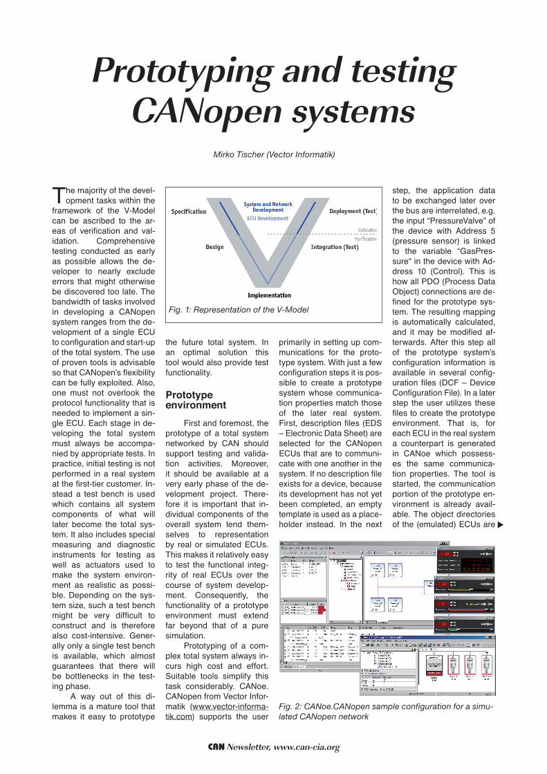
step, the application data to be exchanged later over the bus are interrelated, e.g. the input “PressureValve” of the device with Address 5 (pressure sensor) is linked to the variable “GasPres-sure“ in the device with Ad-dress 10 (Control). This is how all PDO (Process Data Object) connections are de-fined for the prototype sys-tem. The resulting mapping is automatically calculated, and it may be modified af-terwards. After this step all of the prototype system’s configuration information is available in several config-uration files (DCF – Device Configuration File). In a later step the user utilizes these files to create the prototype environment. That is, for each ECU in the real system a counterpart is generated in CANoe which possess-es the same communica-tion properties. The tool is started, the communication portion of the prototype en-vironment is already avail-able. The object directories of the (emulated) ECUs are
Tool
Fig. 2: CANoe.CANopen sample configuration for a simu-lated CANopen network
Fig. 1: Representation of the V-Model

CAN Newsletter, www.can-cia.org
accessed by SDOs (Service Data Objects); it is possible to make additional changes within these directories.
Application behaviorAlso of interest in pro-
totyping is the application behavior of the individual ECUs in the system. This behavior cannot be derived from the EDS files, because only the framework of an object directory is repre-sented there. Generally, the formulation of application behavior is associated with additional programming ef-fort. The software tool with its integrated CAPL pro-gramming language de-scribes ECU behavior very simply. An alternative would be to describe ECU behav-ior in a DLL. Such a DLL is written in C or C++ and is then linked to the pro-totype environment under the tool. It is also possible to integrate Matlab/Simu-link models trouble-free. Depending on the required level of detail, the proto-type can always be refined afterwards.Upon comple-tion of the prototype system there follow the necessary tests of the total system. In this context the tool offers support, both in the creat-ing the tests and in evaluat-ing and logging them. The test functionality required of a CANopen system en-compasses several levels: Protocol level:
An example of this is testing of the SDO protocol as defined by the conformity test of the organization CiA e.V. This involves sending a request to the DUT (device under test), then evaluat-ing the received response. This is a way to test wheth-er CANopen-specific com-munication protocols have been implemented cor-rectly in an individual de-vice within a total system. Communication level:
The correctness of the protocol is not tested here, rather a check is made to verify proper logical flow of (independent) protocol se-quences, e.g. in the config-uration of PDOs. In the case of PDOs, the PDO-relevant entries in the object direc-tory must be written in a specific order. Observance of this order can be test-ed (Good Cases), as can the reaction of the DUT to a faulty order (Bad Cases). Creating this test requires detailed CANopen know-how. Primarily this task in-volves working with the in-terdependencies between the different communication mechanisms that are used.
Application level: Application tests check the interrelationships between process variables. To even be capable of determin-ing these interrelationships the following prerequisites must be satisfied: The pro-cess variables must be ex-changed by PDOs and the
system must be fully config-ured. For example, the state of a valve might be tested as a function of temperature or pressure. Such examples suggest that it is clearly the user who must formulate the test.
Test procedures Under the tool, test
procedures are formulated with the help of the integrat-ed CAPL programming lan-guage. The developer uses this language to formulate extremely flexible tests for complex communication systems.
Each CAPL test mod-ule is a separate test con-sisting of many individual test cases. In turn, each of these test cases contains a number of test steps. Dur-ing test execution the tool runs through the individu-al test cases sequentially. Suitable test flow control could enable skipping or repeating of specific tests. A dynamic aspect is intro-duced to test functionality in this way. The process of building test cases is great-ly simplified by predefined CAPL functions. A typi-cal test sequence might be structured as follows: After stimulation of the DUT, the tester waits for the response which is then evaluated. There are functions for syn-chronizing the test proce-dure to events such as re-ceipt of a specific message or a changed environment variable value (which might also be modified via COM). At the same time fulfillment of other conditions and con-straints can be monitored in quasi background. This approach makes sense if,
Tool
while waiting for a specific message, the user wishes to check whether a different message is being sent pe-riodically on the bus. Espe-cially when setting up auto-matically executable tests, it is important to keep a de-tailed record of the results of individual test steps. Oth-er CAPL functions may be used to write test results to an XML file for post-pro-cessing. The results are also available as an HTML file for immediate evalua-tion. The tool’s test proce-dures may also be specified under XML. This is prefera-ble if many similar test pro-cedures are being gener-ated with a tool. The tool utilizes a large number of test patterns specified in XML and can process them suitably.
SummaryPrototyping in CAN-
open-networked systems is always associated with significant effort. Neverthe-less, prototyping is often es-sential in order to arrive at conclusions regarding func-tionality and system per-formance without having to wait until a very late project phase. The user gets sup-port in creating a prototype from special tools. In par-ticular, coverage of tech-nical communication re-quirements is very easy to implement. The tool’s test functionality lets the system developer perform verifica-tion work in every phase of a project, right up to the fin-ished system.
mirko.tischer@ vector-informatik.de
Fig. 3: Overview
of the ”CANoe.
CANopen” Environ-
ment
Fig. 4: CANopen test levels

![J1939 CANopen gateway - umu.se · J1939-CANopen gateway _____ 24 3 CANopen CANopen [3] is a higher layer protocol for CAN based networks. It is an offspring from CAL (see Section](https://img.dokumen.tips/doc/110x75/5e7174efe1907e55be07658a/j1939-canopen-gateway-umu-j1939-canopen-gateway-24-3-canopen-canopen-3.jpg)