Embed Size (px)
Citation preview

RM-RK252
30˚
1
Parts list for installation and connectionThe following parts are provided for this unit.If anything is missing, contact your dealer immediately.
KW-AV50Installation/Connection Manual
ENGLISHThis unit is designed to operate on 12 V DC, NEGATIVE ground electrical systems. If your vehicle does not have this system, a voltage inverter is required, which can be purchased at JVC car audio dealers.
WARNINGS• DO NOT install any unit or wire any cable in a location where;
– it may obstruct the steering wheel and gearshift lever operations, as this may result in a traffic accident.
– it may obstruct the operation of safety devices such as air bags, as this may result in a fatal accident.
– it may obstruct visibility.• DO NOT operate any unit while manipulating the steering wheel, as this may result in a traffic
accident.• The driver must not watch the monitor while driving. It may lead to carelessness and cause an
accident.• If you need to operate the unit while driving, be sure to look around carefully or you may be
involved in a traffic accident.• If the parking brake is not engaged, “Parking Brake” appears on the monitor, and no playback
picture will be shown.– This warning appears only when the parking brake lead is connected to the parking brake
system built in the car.
To prevent short circuits, we recommend that you disconnect the battery’s negative terminal and make all electrical connections before installing the unit.• Be sure to ground this unit to the car’s chassis again after installation.• Be sure any cable is not caught on the car’s chassis or under seats.
Notes on electrical connections:• Replace the fuse with one of the specified rating. If the fuse blows frequently, consult your JVC
car audio dealer.• It is recommended to connect speakers with maximum power of more than 50 W (both at the
rear and at the front, with an impedance of 4 Ω to 8 Ω). If the maximum power is less than 50 W, change <Amplifier Gain> setting to prevent the
speakers from being damaged (see page 42 of the INSTRUCTIONS).• To prevent short circuits, cover the terminals of the UNUSED leads with insulating tape.• The heat sink becomes very hot after use. Be careful not to touch it when removing this unit.• At the time of installation, be sure to fix all wires (wires both from this unit and from the car
itself) in a way that any wires cannot come into contact with heat sinks on the rear and side of the unit.
Heat sink
LVT2288-002A[U]
0911NSHMDWJEINEN, CT, TH
© 2011 JVC KENWOOD Corporation
Round head screws(M5 x 8 mm)
Flat head screws (M5 x 8 mm)
Main unit
Power cord
Batteries
Remote controller
Crimp connector
Monitor panel and soft case
INSTALLATION (IN-DASH MOUNTING)The following illustration shows a typical installation. However, you should make adjustments corresponding to your specific car. If you have any questions or require information regarding installation kits, consult your JVC car audio dealer or a company supplying kits.• If you are not sure how to install this unit correctly, have it installed by a qualified technician.
Before installing the unit• When mounting the unit, be sure to use the screws provided, as instructed. If other screws are used, parts could
become loose or damaged.• When tightening screws or bolts, be careful not to pinch any connection cord.• Make sure not to block the fan on the rear to maintain proper ventilation when installing the unit.
1 Remove the audio system originally installed in the car, together with its mounting brackets.• Be sure to keep all the screws and parts removed from your car for future use.
2 Attach the mounting brackets (removed from the car) to this unit (see below).• Use flat head screws or round head screws, depending on installation location.• When you need to use round head screws, use the supplied screws and the screws used to attach the metal
protection plates to the unit when shipped.
3 Do the required electrical connections.• See “ELECTRICAL CONNECTIONS” on pages 1 and 2.
4 Install this unit using the screws removed in step 1.
5 Attach the monitor panel (see below).
Install the unit at an angle of less than 30˚.
Connecting the parking brake lead
Parking brake
Parking brake switch (inside the car)
Parking brake lead (light green)
To metallic body or chassis of the car
Crimp connector
ELECTRICAL CONNECTIONS
PRECAUTIONS on power supply and speaker connections:• DO NOT connect the speaker leads of the power cord to the car battery; otherwise,
the unit will be seriously damaged.• BEFORE connecting the speaker leads of
the power cord to the speakers, check the speaker wiring in your car.
TROUBLESHOOTING
Supplied screws
Mounting bracket removed from the car
Screws removed from the car in step 1Supplied screws
Select the appropriate type fitting to your audio system space.
Monitor panel
If necessary, restore the protruding tabs.
When installing the unit in a Nissan carIf your Nissan car needs a plate, purchase the plate separately.
Plate for use with a Nissan car (not supplied)
Step 5
• When you use screws other than those supplied, use 8 mm-long screws. If longer screws are used, they could damage the unit.
• Tighten the screws firmly to prevent the unit from falling off.
Locate the reverse lamp lead in the trunk. Extension lead (not supplied for this unit)Purple with white stripe
Reverse lamps
To reverse lamps
Reverse lamp lead
Connecting the reverse gear signal lead (for rear view camera)
Crimp connector (not supplied for this unit)
• The fuse blows.* Are the red and black leads connected
correctly?• Power cannot be turned on.* Is the yellow lead connected?• No sound from the speakers.* Is the speaker output lead short-circuited?• Sound is distorted.* Is the speaker output lead grounded?* Are the “–” terminals of L and R speakers
grounded in common?
• Noise interfere with sounds.* Is the rear ground terminal connected to
the car’s chassis using shorter and thicker cords?
• This unit becomes hot.* Is the speaker output lead grounded?* Are the “–” terminals of L and R speakers
grounded in common?• This unit does not work at all.* Have you reset your unit?
Remove the metal protection plates from the unit before installation.• Keep the round head screws (M5 x 8 mm) used to attach the metal protection plates. You
may need to use the screws for installation.
The following example is for installation in a Toyota car. For more details, consult your JVC car audio dealer.
Extension lead
Extension lead
EN_1-2_KW-AV50[U].indd 1EN_1-2_KW-AV50[U].indd 1 11.9.15 6:25:10 PM11.9.15 6:25:10 PM
*1
*11
2
3
4
5
6
7
8
3 1CAMERA IN
SUBWOOFER OUT
PARKING BRAKE
REVERSEGEAR
SIGNAL
STEERINGWHEEL
REMOTE
2
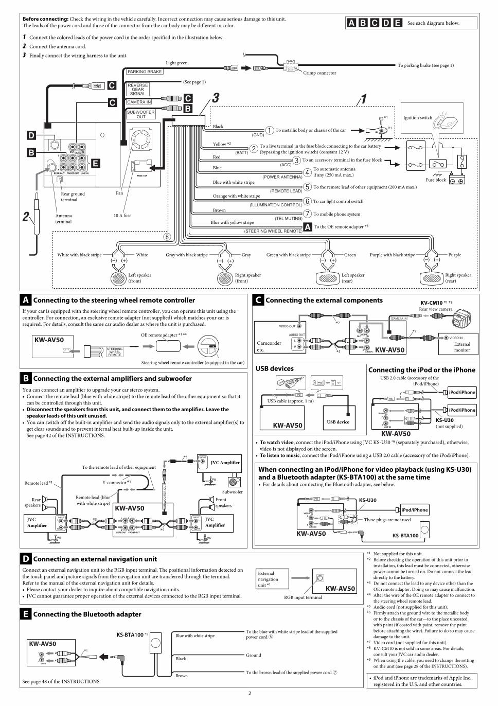
Before connecting: Check the wiring in the vehicle carefully. Incorrect connection may cause serious damage to this unit.The leads of the power cord and those of the connector from the car body may be different in color.
1 Connect the colored leads of the power cord in the order specified in the illustration below.
2 Connect the antenna cord.
3 Finally connect the wiring harness to the unit.
See each diagram below.
Black
Yellow *2
Red
Orange with white stripe
Brown
Light green
Blue with white stripe
Blue
To the OE remote adapter *3
To metallic body or chassis of the car
To a live terminal in the fuse block connecting to the car battery (bypassing the ignition switch) (constant 12 V)
To an accessory terminal in the fuse block
To car light control switch
To mobile phone system
To automatic antenna if any (250 mA max.)
To the remote lead of other equipment (200 mA max.)
Crimp connector
White with black stripe White Gray with black stripe Gray Green with black stripe Green Purple with black stripe Purple
Left speaker (front)
Right speaker (front)
Left speaker (rear)
Right speaker (rear)
10 A fuse
FanRear ground terminal
Antenna terminal
Connecting to the steering wheel remote controllerIf your car is equipped with the steering wheel remote controller, you can operate this unit using the controller. For connection, an exclusive remote adapter (not supplied) which matches your car is required. For details, consult the same car audio dealer as where the unit is purchased.
A
OE remote adapter *1 *4
Steering wheel remote controller (equipped in the car)
*5
*5
*5
*6 *6
*6
Connecting the external amplifiers and subwooferYou can connect an amplifier to upgrade your car stereo system.• Connect the remote lead (blue with white stripe) to the remote lead of the other equipment so that it
can be controlled through this unit.• Disconnect the speakers from this unit, and connect them to the amplifier. Leave the
speaker leads of this unit unused.• You can switch off the built-in amplifier and send the audio signals only to the external amplifier(s) to
get clear sounds and to prevent internal heat built-up inside the unit. See page 42 of the INSTRUCTIONS.
B
Subwoofer
JVC Amplifier
JVC Amplifier
JVC Amplifier
Remote lead *1
Rear speakers
Front speakers
To the remote lead of other equipment
Remote lead (blue with white stripe)
Y-connector *1
*7
*5
*7
CAMERA IN
Connecting the external components C
Camcorder etc.
External monitor
KV-CM10 *1 *8
Rear view camera
USB devices
USB cable (approx. 1 m)
USB device
Connecting the iPod or the iPhone
KS-U30(not supplied)
USB 2.0 cable (accessory of the iPod/iPhone)
*1 Not supplied for this unit.*2 Before checking the operation of this unit prior to
installation, this lead must be connected, otherwise power cannot be turned on. Do not connect the lead directly to the battery.
*3 Do not connect the lead to any device other than the OE remote adapter. Doing so may cause malfunction.
*4 Alter the wire of the OE remote adapter to connect to the steering wheel remote lead.
*5 Audio cord (not supplied for this unit).*6 Firmly attach the ground wire to the metallic body
or to the chassis of the car—to the place uncoated with paint (if coated with paint, remove the paint before attaching the wire). Failure to do so may cause damage to the unit.
*7 Video cord (not supplied for this unit).*8 KV-CM10 is not sold in some areas. For details,
consult your JVC car audio dealer.*9 When using the cable, you need to change the setting
on the unit (see page 28 of the INSTRUCTIONS).
• iPod and iPhone are trademarks of Apple Inc., registered in the U.S. and other countries.
Connecting an external navigation unitDConnect an external navigation unit to the RGB input terminal. The positional information detected on the touch panel and picture signals from the navigation unit are transferred through the terminal. Refer to the manual of the external navigation unit for details.• Please contact your dealer to inquire about compatible navigation units.• JVC cannot guarantee proper operation of the external devices connected to the RGB input terminal.
External navigation unit *1
RGB input terminal
Fuse block
Ignition switch
(See page 1)
To parking brake (see page 1)
E Connecting the Bluetooth adapter
To the brown lead of the supplied power cord 7
To the blue with white stripe lead of the supplied power cord 5
Ground*1
Blue with white stripe
Black
Brown
KS-BTA100 *1
See page 48 of the INSTRUCTIONS.
Blue with yellow stripe
• To watch video, connect the iPod/iPhone using JVC KS-U30 *9 (separately purchased), otherwise, video is not displayed on the screen.
• To listen to music, connect the iPod/iPhone using a USB 2.0 cable (accessory of the iPod/iPhone).
When connecting an iPod/iPhone for video playback (using KS-U30) and a Bluetooth adapter (KS-BTA100) at the same time• For details about connecting the Bluetooth adapter, see below.
These plugs are not used
KS-BTA100
KS-U30
EN_1-2_KW-AV50[U].indd 2EN_1-2_KW-AV50[U].indd 2 11.9.15 6:25:13 PM11.9.15 6:25:13 PM

3
中文
本機僅可使用直流 12 V、負極接地的電源系統。如果您的車輛沒有這一電源系統,則需要一個電壓變換器,可以在 JVC 汽車音響分銷商處買到。
警告• 切勿在以下位置安裝本機或連接電纜;
– 可能會妨礙方向盤和變速排檔桿的操作,引發交通事故。– 可能會妨礙操作安全裝置,如安全氣袋等,引發致命的交通事故。– 可能會妨礙視野。
• 切勿在操作方向盤的過程中操作本機,否則可能引發交通事故。• 駕駛時,駕駛員切勿緊盯顯示器。這可能會導致疏忽並引發事故。• 在駕駛過程中若需要操作本機,切記要密切注意前方,否則可能引發交通事故。• 若手煞車未嚙合,“Parking Brake(手煞車)”字樣在顯示器上出現,且無法播放圖片。– 僅當手煞車導線與汽車內置的手煞車系統相連接時此警告信息才會出現。
為防止短路,建議在安裝本機之前,拔開電池的負極,並把所有電路都連接好。• 安裝完畢後務必將本機的地線重新接至車身。• 確定沒有任何電纜纏繞在汽車底盤上或座位下方。
進行電路連接時注意:• 把保險絲更換為額定負荷值的保險絲。如果保險絲經常燒壞,請向 JVC 汽車音響分銷商詢問。
• 後置和前置揚聲器的最大輸入功率應大於 50 W,其阻抗為 4 Ω – 8 Ω。 如果最大功率少於 50 W,請調校 <Amplifier Gain> 設定值,以防止揚聲器損壞(參閱使用說明書的第 42 頁)。
• 為防止短路,請用絕緣帶包住未使用電線的端子。• 本機使用後,散熱片會很熱。因此,在移出本機時,小心不要觸摸散熱片。• 安裝的時候請務必固定住所有電線(本機和汽車本身的電線),使任何電線不會和本機後面板和側面板上的散熱片接觸。
散熱片
安裝(裝設、固定在儀表板內)下面的圖解表示了典型的安裝程序。但是在實際安裝時,您應該根據您的汽車作適當的調整。如果您有問題,或需要有關配套元件的資料,請向 JVC 汽車音響分銷商或配套元件供應公司詢問。• 如果您不能確定如何正確地安裝本機,應請合格的技術人員來安裝。
安裝本機之前• 當裝上本機時,必須按照指示使用配備的螺絲釘。如果使用其它的螺絲釘,相關零件可能會鬆脫或損壞。
• 當鎖緊螺絲釘或螺栓時,切記不要壓擠到任何連接電線。• 當安裝上後,切記不要阻擋到後面板的風扇以維持適當的通風。
1 拆卸原本安裝在汽車內的音響系統,以及其裝配架。• 請務必保留所有從您汽車拆卸的螺絲和零件做日後使用。
2 將(從汽車拆卸的)裝配架安上本機(參閱下列內容)。• 根據安裝位置使用平頭螺絲或圓頭螺絲。• 當您需要使用圓頭螺絲時,請使用配備的螺絲和出廠時就已用來將金屬保護框安裝至本機的螺絲。
3 執行必要的電路連接。• 參閱第 3 和 4 頁的“電路連接”。
4 使用在步驟 1 拆卸的螺絲安裝本機。5 安裝顯示器面板(參閱下列內容)。
連接至手煞車導線
手煞車
手煞車開關(位於車內)
手煞車導線(淺綠色)
接至金屬體或汽車底盤
夾子接頭
電路連接
30˚
將本機安裝在少於 30˚ 的角度。
配備螺絲從汽車拆卸的裝配架
在步驟 1 從汽車拆卸的螺絲配備螺絲
選擇適合您的音響系統安裝空間的型號。
顯示器面板
若有必要,請重新裝上凸緣。
當安裝本機於日產汽車時若有需要,請另購用於日產汽車的框。
用於日產汽車的框(另購)
步驟 5
• 當您使用的不是配備的螺絲時,請使用 8 mm 長的螺絲。若使用比較長的螺絲,有關螺絲可能會損壞本機。
• 擰緊螺絲以防本機摔落。
找出後車箱的倒車信號燈導線。 延長導線(不隨本機提供)
紫色帶有白色條紋
倒車信號燈
連接至倒車信號燈
倒車信號燈導線
連接反向變速器信號導線(對應後視照相機)
夾子接頭(不隨本機提供)
以下以豐田(Toyota)汽車安裝為例。請聯絡您的 JVC 汽車音響分銷商有關更多細節。
延長導線
電源和揚聲器接線注意事項:• 切勿把揚聲器導線接頭接至電池,否則本機將會嚴重損壞。• 在把揚聲器導線接頭接至揚聲器之前,檢查您汽車上的揚聲器線路。
故障排除• 保險絲燒斷。* 檢查紅色導線接頭和黑色導線接頭是否正確接上?
• 電源不能接通。* 檢查黃色導線接頭是否接上?• 揚聲器沒有聲訊。* 檢查揚聲器輸出導線接頭是否短路?• 聲訊失真。* 檢查揚聲器輸出導線接頭是否接地?* 檢查揚聲器的左(L),右(R)端子的負極“–”是否共同接地?
• 噪音干擾音響。* 後接地端子與車身是否使用較短和較厚的電線連接?
• 本機發熱。* 檢查揚聲器輸出導線接頭是否接地?* 檢查揚聲器的左(L),右(R)端子的負極“–”是否共同接地?
• 本機完全不能正確操作。* 您有沒有重置本機?
RM-RK252
用於安裝和連接的零件清單本機配備以下零件。若發現缺少任何一件零件,請即刻聯絡您的分銷商。
圓頭螺絲(M5 x 8 mm)
平頭螺絲(M5 x 8 mm)
主機
電源線
電池
遙控器
夾子接頭
顯示器面板和軟盒
安裝前請從本機上卸下金屬保護框。• 請妥善保管用於安裝金屬保護框的圓頭螺絲(M5 x 8 mm)。您可能需要使用這些螺絲來進行安裝。
延長導線
Install_3-4_KW-AV50[U]f.indd 3 9/27/11 9:23:00 AM
*1
*11
2
3
4
5
6
7
8
3 1CAMERA IN
SUBWOOFER OUT
PARKING BRAKE
REVERSEGEAR
SIGNAL
STEERINGWHEEL
REMOTE
4
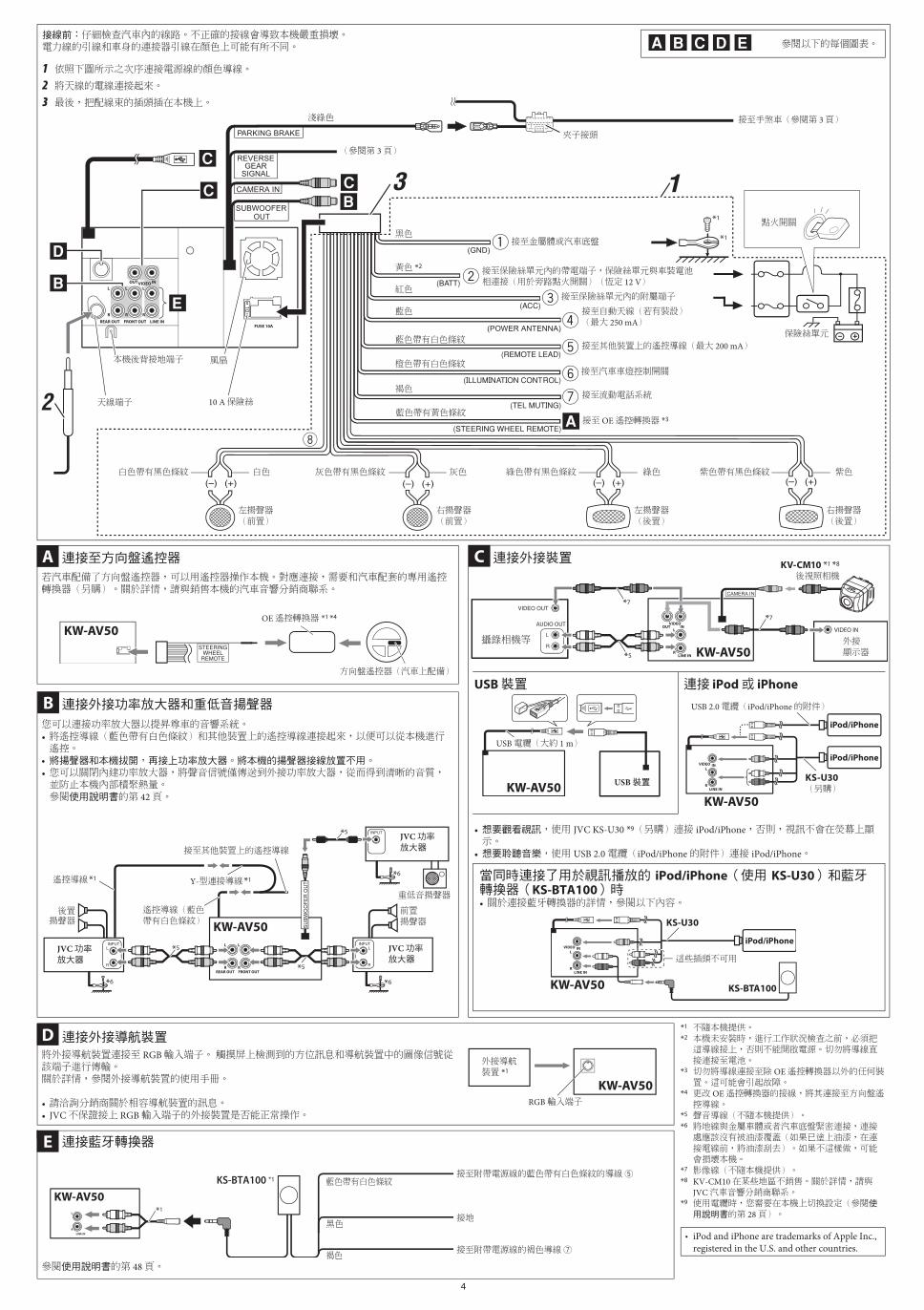
接線前:仔細檢查汽車內的線路。不正確的接線會導致本機嚴重損壞。電力線的引線和車身的連接器引線在顏色上可能有所不同。
1 依照下圖所示之次序連接電源線的顏色導線。2 將天線的電線連接起來。3 最後,把配線束的插頭插在本機上。
參閱以下的每個圖表。
黑色
黃色 *2
紅色
橙色帶有白色條紋
褐色
淺綠色
藍色帶有白色條紋
藍色
接至 OE 遙控轉換器 *3
接至金屬體或汽車底盤
接至保險絲單元內的帶電端子,保險絲單元與車裝電池相連接(用於旁路點火開關)(恆定 12 V)
接至保險絲單元內的附屬端子
接至汽車車燈控制開關
接至流動電話系統
接至自動天線(若有裝設)(最大 250 mA)
接至其他裝置上的遙控導線(最大 200 mA)
夾子接頭
白色帶有黑色條紋 白色 灰色帶有黑色條紋 灰色 綠色帶有黑色條紋 綠色 紫色帶有黑色條紋 紫色
左揚聲器(前置)
右揚聲器(前置)
左揚聲器(後置)
右揚聲器(後置)
10 A 保險絲
風扇本機後背接地端子
天線端子
連接至方向盤遙控器
若汽車配備了方向盤遙控器,可以用遙控器操作本機。對應連接,需要和汽車配套的專用遙控轉換器(另購)。關於詳情,請與銷售本機的汽車音響分銷商聯系。
A
OE 遙控轉換器 *1 *4
方向盤遙控器(汽車上配備)
*5
*5
*5
*6 *6
*6
連接外接功率放大器和重低音揚聲器
您可以連接功率放大器以提昇尊車的音響系統。• 將遙控導線(藍色帶有白色條紋)和其他裝置上的遙控導線連接起來,以便可以從本機進行遙控。
• 將揚聲器和本機拔開,再接上功率放大器。將本機的揚聲器接線放置不用。• 您可以關閉內建功率放大器,將聲音信號僅傳送到外接功率放大器,從而得到清晰的音質,並防止本機內部積聚熱量。參閱使用說明書的第 42 頁。
B
重低音揚聲器
JVC 功率放大器
JVC 功率放大器
JVC 功率放大器
遙控導線 *1
後置揚聲器
前置揚聲器
接至其他裝置上的遙控導線
遙控導線(藍色帶有白色條紋)
Y-型連接導線 *1
*7
*5
*7
CAMERA IN
連接外接裝置D
攝錄相機等 外接顯示器
KV-CM10 *1 *8
後視照相機
USB 裝置
USB 電纜(大約 1 m)
USB 裝置
連接 iPod 或 iPhone
KS-U30(另購)
USB 2.0 電纜(iPod/iPhone 的附件)
• 想要觀看視訊,使用 JVC KS-U30 *9(另購)連接 iPod/iPhone,否則,視訊不會在熒幕上顯示。
• 想要聆聽音樂,使用 USB 2.0 電纜(iPod/iPhone 的附件)連接 iPod/iPhone。
*1 不隨本機提供。*2 本機未安裝時,進行工作狀況檢查之前,必須把這導線接上,否則不能開啟電源。切勿將導線直接連接至電池。
*3 切勿將導線連接至除 OE 遙控轉換器以外的任何裝置。這可能會引起故障。
*4 更改 OE 遙控轉換器的接線,將其連接至方向盤遙控導線。
*5 聲音導線(不隨本機提供)。*6 將地線與金屬車體或者汽車底盤緊密連接,連接處應該沒有被油漆覆蓋(如果已塗上油漆,在連接電線前,將油漆刮去)。如果不這樣做,可能會損壞本機。
*7 影像線(不隨本機提供)。*8 KV-CM10 在某些地區不銷售。關於詳情,請與
JVC 汽車音響分銷商聯系。*9 使用電纜時,您需要在本機上切換設定(參閱使用說明書的第 28 頁)。
• iPod and iPhone are trademarks of Apple Inc., registered in the U.S. and other countries.
保險絲單元
點火開關
(參閱第 3 頁)
接至手煞車(參閱第 3 頁)
連接藍牙轉換器
接至附帶電源線的褐色導線 7
接至附帶電源線的藍色帶有白色條紋的導線 5
接地*1
藍色帶有白色條紋
黑色
褐色
KS-BTA100 *1
參閱使用說明書的第 48 頁。
藍色帶有黃色條紋
E
將外接導航裝置連接至 RGB 輸入端子。 觸摸屏上檢測到的方位訊息和導航裝置中的圖像信號從該端子進行傳輸。關於詳情,參閱外接導航裝置的使用手冊。
• 請洽詢分銷商關於相容導航裝置的訊息。• JVC 不保證接上 RGB 輸入端子的外接裝置是否能正常操作。
外接導航裝置 *1
RGB 輸入端子
連接外接導航裝置D
C
當同時連接了用於視訊播放的 iPod/iPhone(使用 KS-U30)和藍牙轉換器(KS-BTA100)時• 關於連接藍牙轉換器的詳情,參閱以下內容。
這些插頭不可用
KS-BTA100
KS-U30
Install_3-4_KW-AV50[U]f.indd 4 9/27/11 9:23:01 AM

RM-RK252
30˚
5
รายการชนสวนสำหรบการตดตงและการเชอมตอชนสวนตอไปนจดสงใหพรอมเครองน
หากมสงใดขาดหายไป โปรดตดตอตวแทนจำหนายของคณทนท
ไทย
อปกรณ น ได รบ การ ออกแบบ เพอ ใช งาน กบ ระบบ ไฟฟา สายดนขวลบ กระแสตรง 12 โวลต หาก รถยนต ของ คณ ไม ได
ใชระบบ น ตอง ใช เครอง แปลง กระแส ไฟ ซง สามารถ หา ซอ ได จากตวแทน จำหนาย เครอง เสยง ตด รถยนต JVC
คำเตอน• อยาตดตงเครองหรอตอสายไฟในตำแหนงท
– อาจ กดขวาง การ ทำงาน ของ พวง มาลย และ คน เกยร เพราะ อาจ เปน สาเหต ให เกด อบตเหต ทาง รถยนต
– อาจ กดขวาง การ ทำงาน ของ อปกรณ ปองกน ความ ปลอดภย เชน ถง ลม นรภย เพราะ อาจ เปน สาเหต ให เกด อบตเหต
ราย แรง
– อาจบดบงสายตา
• อยา ใช งาน เครอง ใน ขณะ ขบข เพราะ อาจ เปน สาเหต ให เกดอบตเหต ทาง รถยนต
• ผขบขตองไมมองจอภาพขณะขบข เพราะอาจนำไปสความประมาทและเปนเหตใหเกดอบตเหตได• ถาตองใชเครองขณะขบรถ ขอใหแนใจวาดทางรอบคอบดแลว มเชนนนอาจเกดอบตเหตขนได• หาก ไม ได เขา เบรค ขอความ “Parking Brake(เบรก จอด รถ)” จะ ปรากฏ บน หนา จอ และ ไม แสดง ภาพ การ เลน ใดๆ
– คำ เตอน น จะ ปรากฏ ขน ตอ เมอ สาย เบรค เชอม ตอ กบ ระบบเบรค ท ตด ตง อย ใน รถ เทานน
เพอ ปองกน ไฟฟา ลดวงจร ขอ แนะนำ ให คณ ถอด ขวลบ ของ แบตเตอร และ ทำการ เชอม ตอ ระบบ ไฟฟา ทงหมด ให
เรยบรอย กอน ตด ตง เครอง น
• ตรวจสอบใหแนใจวาตดตงเครองกบโครงรถกอนการตดตง• ตองแนใจวา ไมมสายเคเบลใดๆ ตดอยทแชสซรถยนตหรอใตทนง
หมายเหตเกยวกบการเชอมตอทางไฟฟา:• หากฟวสขาดบอยๆ สอบถามตวแทนจำหนายเครองเสยงตดรถยนต JVC ของคณ
• ขอแนะนำใหเชอมตอลำโพงกบกำลงไฟสงกวา 50 วตต (ทงดานหลงและดานหนง โดยมคาความตานทานท 4 Ω ถง
8 Ω) หากกำลงไฟสงสดตำกวา 50 วตต เปลยนการตงคา <Amplifier Gain> เพอปองกนไม ใหลำโพงเสยหาย (ดหนา
42 ของคำแนะนำ)• เพอปองกนไฟฟาลดวงจร พนขวตอของสายไฟท ไม ได ใชงานดวยเทปพนสายไฟ• แผนระบายความรอนรอนมากหลงใชงาน หามสมผสเมอถอดเครองออก
• ในระหวางการตดตง โปรดแนใจวาจดการกบสายทงหมด
(ทงสายจากตวเครองและจากในรถยนตเอง) โดยไมมสายใดสมผสกบแผนระบายความรอนทดานหลงและดานขางของเครอง
แผนระบายความรอน
สกรหวกลม
(M5 x 8 มม)ตะปควงหวแบน
(M5 x 8 มม)
ตวเครอง
สายตอ
แบตเตอร
รโมทคอนโทรล
ชอง เสยบ แบบ หนบ เขา หว สาย
แผงจอภาพและกลองบรรจแบบออน
การตดตง (การตดตงในแผงหนาป ทม)ภาพ ประกอบ ตอ ไป น แสดง การ ตด ตง แบบ ปกต อยางไร กตาม คณ ควร ทำการ ปรบ เปลยน ให เหมาะ กบ รถยนต ของ คณ หาก ทาน ม คำถาม หรอ ตองการ ขอมล เกยว กบ ชด ตด ตง โปรด ปรกษา ตวแทน จำหนาย เครอง เสยง ตด รถยนต JVC ของ ทาน หรอ บรษท ท จดหา ชด อปกรณ ให• หาก คณ ไม มนใจ ใน การ ตด ตง อปกรณ ชด น ได อยาง ถก ตอง ให ชาง เทคนค ผ ชำนาญ การ ทำการ ตด ตง
กอนตดตงอปกรณชดน• เมอทำการตดตง โปรดแนใจวาใชสกรท ให ไว ตามคำแนะนำ หากใชสกรแบบอน ชนสวนอาจหลวมหลดหรอไดรบความเสยหายได• เมอขนสกรหรอสลกเกลยว ระวงอยาเจาะถกสายใดๆ ทเชอมตออย• โปรดแนใจวาไม ไดปดกนพดลมทดานหลง เพอใหสามารถระบายความรอนไดอยางเหมาะสมเมอตดตงเครอง
1 ถอดระบบเครองเสยงใดๆ ทตดตงไว ในรถยนต รวมถงแทนรองรบการตดตง• อยา ลม เกบ สก ร ทงหมด และ ชน สวน ท ถอด ออก จากรถยนต ของ คณ ไว ใช ใน อนาคต
2 ตดแทนรองรบการตดตง (ทถอดออกจากรถ) เขากบเครองน (ดดานลาง)• ใชสกรหวแบนหรอสกรหวกลม ขนอยกบตำแหนงทตดตง• เมอ คณ ตอง ใช สก ร หว กลม ให ใช สก ร ท จด สง ให และสก ร ท ตด แผน โลหะ ปองกน เขา กบ เครอง เมอ ครง จด สง
3 เชอมตอไฟฟาทจำเปน• ดท “การเชอมตอไฟฟา” ในหนา 5 และหนา 6
4 ตดตงเครองนโดยใชสกรทถอดออกมา ในขนตอน 15 ตดแผงจอภาพ (ดดานลาง)
ตดตงเครองในมมนอยกวา 30˚
การเชอมตอสายเบรค
เบรค
สวตชเบรค ( ในรถยนต)
สายเบรค (สเขยวออน)
สำหรบ ตว เครอง ท เปน โลหะ
หรอ โครง รถ
ชอง เสยบ แบบ
หนบ เขา หว สาย
การเชอมตอไฟฟา
ขอควรระวงเกยวกบการเชอมตอแหลงจายไฟและลำโพง:• อยา ตอ สาย ลำ โพง ท เป น สาย ไฟ กบ แบตเตอร รถยนต ไม เชน นน เครอง อาจ ได รบ ความ เสย หาย ราย แรง
• กอน ตอ สาย ลำโพง ท เปน สาย ไฟ กบ ลำโพง ควร ตรวจ
สอบ การ เดน สาย ลำโพง ใน รถ ของ ทาน
การแก ไขป ญหาเบองตน
สกรทจดสงใหถอดขายดจากรถ
สกรทถอดออกจากรถยนต ในขนตอน 1สกรทจดสงให
เลอก ตว ยด ประเภท
ท เหมาะ สม กบ พนท
ของ ระบบ เครอง เสยง
ของ คณ
แผงจอภาพ
หากจำเปน ให ใสแถบยนกลบคน
เมอตดตงเครองนในรถยนตนสสนหากการตดตงในรถยนตนสสนตองใชแผนโลหะ ใหซอแยกตางหาก
แผน โลหะ สำหรบ ใช กบ รถ ยนต
นส สน ( ไม ได จด สง ให)
ขนตอน 5
• หาก คณ ใช สก ร แบบ อน นอก เหนอ จาก ท จด สง ให
ให ใช สก ร ความยาว 8 มม. หาก ใช สก ร ยาว กวา นน อาจ สราง ความ เสย หาย กบ เครอง ได
• ขนสกรใหแนนเพอปองกนเครองรวงหลน
คนหาสายไฟไฟถอยหลงในกระโปรงทาย สายตอ ( ไมไดจดสงใหสำหรบเครองน)
สมวงทมแถบสขาว
ไฟถอยหลง
ตอกบไฟถอยหลง
สายไฟไฟถอยหลง
การเชอมตอสายสญญาณเกยรถอยหลง (สำหรบกลองมองหลง)
ชองเสยบแบบหนบเขาหวสาย
( ไมไดจดสงใหสำหรบเครองน)
• ฟวสขาด* ตอสายสแดงและสดำถกตองหรอไม?• ไมสามารถเปดเครองได* ตอสายสเหลองแลวหรอไม?• ไม ไดยนเสยงจากลำโพง* สายสญญาณออกของลำโพงลดวงจรหรอไม?• เสยงผดเพยน* สายสญญาณออกของลำโพงตอกบสายดนหรอไม?* ขวตอ “–” ของลำโพง L (ซาย) และ R (ขวา) ตอสายดนไวดวยกนหรอไม?
• มเสยงรบกวน* ขว ตอ สายดน ดาน หลง ท ตอ กบ โครง รถ ใช สาย ท สน และหนา กวา หรอ ไม?
• เครองรอน* สายสญญาณออกของลำโพงตอกบสายดนหรอไม?* ขวตอ “–” ของลำโพง L (ซาย) และ R (ขวา) ตอสายดนไวดวยกนหรอไม?
• เครองใชงานไม ไดเลย* ทานตงเครองใหม ใชหรอไม?
ถอดแผนโลหะปองกนออกจากเครองกอนการตดตง
• เกบสกรหวกลม (M5 x 8 มม.) ท ใชยดแผงโลหะปองกนเอาไว คณอาจตองใชสกรนสำหรบการตดตง
ตวอยาง ตอ ไป น สำหรบ การ ตด ตง ใน รถยนต โต โย ตา สำหรบ ราย ละเอยด เพม เตม สอบถาม ตวแทน จำหนาย เครอง เสยง ตด รถยนต JVC ของ คณ
สายตอ
สายไฟ
Install_5-6_KW-AV50[U]f.indd 5 9/27/11 9:23:25 AM

*1
*11
2
3
4
5
6
7
8
3 1CAMERA IN
SUBWOOFER OUT
PARKING BRAKE
REVERSEGEAR
SIGNAL
STEERINGWHEEL
REMOTE
6
กอนเชอมตอ: ตรวจ สอบ สาย ไฟ ใน รถยนต อยาง รอบคอบ การ เชอม ตอ ไม ถก ตอง อาจ สราง ความ เสย หาย รนแรง กบ เครอง น
สาย ไฟ และ สาย ของ ขว ตอ จาก ตว รถยนต อาจ ใช ส ตาง กน
1 เชอมตอสายทมสของสายไฟตามลำดบทระบในภาพประกอบดานลาง
2 เชอมตอสายเสาอากาศ
3 สดทาย เชอมตอชดสายไฟกบเครอง
ดแผนภาพดานลาง
สดำ
สเหลอง *2
สแดง
สสมแถบขาว
สนำตาล
สเขยวออน
สนำเงนทมแถบสขาว
สนำเงน
สำหรบอะแดปเตอรรโมท OE *3
สำหรบตวเครองทเปนโลหะหรอโครงรถ
ตอกบขวตอทมกระแสในบลอกฟวสทเชอมตอกบแบตเตอรรถยนต (เลยงสวตชกญแจสตารท) (คงท 12 V)
ตอกบขวตออปกรณเสรมในบลอกฟวส
สวตซควบคมไฟของรถยนฅร
ตอกบระบบโทรศพทเคลอนท
สำหรบ สาย อากาศ อตโนมต
ถา ม (สงสด 250 mA)
สำหรบสายรโมทของอปกรณอน (สงสด 200 mA)
ชองเสยบแบบหนบเขาหวสาย
สขาวทมแถบสดำ สขาว สเทาทมแถบสดำ สเทา สเขยวทมแถบสดำ สเขยว สมวงทมแถบสดำ สมวง
ลำโพงซาย (หนา) ลำโพงขวา (หนา) ลำโพงซาย (หลง) ลำโพงขวา (หลง)
ฟวส 10 A
พดลมขวตอสายดนดานหลง
ขวตอสายอากาศ
การเชอมตอกบรโมทคอนโทรลทพวงมาลย
หาก รถยนต ของ คณ ม รโมทคอนโทรล ท พวง มาลย ตด ตง อย คณ สามารถ ใช งาน เครอง น โดย ใช รโมท ดง กลาว สำหรบ การ เชอม ตอ
ตอง ใช อะ แดป เตอร รโมท เฉพาะ ( ไม ได จด สง ให) ท เหมาะ สม กบ รถ ของ คณ สำหรบ ราย ละเอยด สอบถาม ตวแทน จำหนาย
เครอง เสยง ตด รถยนต ราย ท คณ ซอ เครอง เสยง น
A
อะแดปเตอรรโมท OE *1 *4
รโมทคอนโทรลทพวงมาลย (ทตดตงในรถยนต)
*5
*5
*5
*6 *6
*6
การเชอมตอเครองขยายเสยงและซบวฟเฟอรภายนอก
คณสามารถเชอมตอเครองขยายเสยงเพอเพมประสทธภาพระบบเสยงสเตอรโอในรถยนตของคณ
• เชอมตอสายรโมท (สนำเงนทมแถบสขาว) กบสายรโมทของอปกรณอน เพอใชสามารถทำการควบคมผานทางเครองน ได
• ถอดสายลำโพงออกจากเครองน และเสยบเขากบเครองขยายเสยง ปลอยสายลำโพงของเครองน ไว โดยไมตองใช
• คณ สามารถ ปด เครอง ขยาย เสยง ใน ตว และ สง สญญาณ เสยง ไป ยง เครอง ขยาย เสยง ภายนอก เทานน เพอ ให ได รบ เสยง ท กระจาง
ชด และ เพอ ปองกน ความ รอน สะสม ภายใน ตว เครอง
ด หนา 42 ใน คำ แนะนำ
B
ซบวเฟอร
แอม พล ฟลาย เอ อร ของ JVC
แอม พล ฟลาย เอ อร ของ JVC
แอม พล ฟลาย เอ อร ของ JVC
สายรโมท *1
ลำโพงหลง ลำโพงหนา
สำหรบสายรโมทของอปกรณอน
สายรโมท
(สนำเงนทมแถบสขาว)
ขอตอ Y *1
*7
*5
*7
CAMERA IN
การเชอมตออปกรณภายนอกC
กลองวดโอ ฯลฯ จอนอก
KV-CM10 *1 *8
กลองมองหลง
อปกรณ USB
สายเคเบล USB (ราว 1 ม.)
อปกรณ USB
การเชอมตอ iPod หรอ iPhone
KS-U30( ไม ไดจดสงให)
สาย USB 2.0 (อปกรณเสรมของ iPod/iPhone)
*1 ไม ได จด สง ให สำหรบ เครอง น*2 กอน ตรวจ สอบ การ ทำงาน ของ เครอง น กอน การ ตด ตง สาย ไฟ ตอง
ตอ ไว แลว ไม เชน นน จะ ไม สามารถ เปด เครอง ได อยา ตอ สาย ไฟ เขา กบ แบตเตอร โดยตรง*3 หาม เชอม ตอ สาย ไฟ กบ อ ปก รณ ใดๆ นอก เหนอ จา กอะ แดป เตอร
รโมท OE เนองจาก อาจ ทำให การ ทำงาน ผด ปกต*4 เปลยน สา ยอะ แดป เตอร รโมท OE เพอ เชอม ตอ สาย
รโมทคอนโทรล บน พวง มาลย*5 สาย สญญาณ เสยง ( ไม ได จด สง ให สำหรบ เครอง น)*6 ตด สายดน กบ ตว ถง รถ สวน ท เปน โลหะ หรอ โครง รถ ให แนน โดย
ตด กบ สวน ท ไมม ส พน ทบ (หาก ม ส พน ทบ อย ให ลอก ส ออก กอน ตด สายดน) หาก ไม ดำเนน การ เชน นน อาจ สง ผล เสย หาย ตอ เครอง
*7 สาย สญญาณ ภาพ ( ไม ได จด สง ให สำหรบ เครอง น)*8 KV-CM10 อาจ ไม ได ใช วสด ท ม ความ แขง ใน บาง สวน โปรด
สอบถาม ราย ละเอยด จาก ตวแทน จำหนาย เครอง เสยง ตด รถยนต JVC ของ คณ
*9 เมอ ใช สาย เคเบล คณ ตอง เปลยน การ ตง คา บน เครอง (ด หนา 28 ของ คำ แนะนำ)
• iPod and iPhone are trademarks of Apple Inc., registered in the U.S. and other countries.
การเชอมตออปกรณนำทางภายนอกDเชอม ตอ อปกรณ นำทาง ภายนอก กบ ขว ตอ รบ สญญาณ RGB ขอมล ตำแหนง ท พบ บน แผง สมผส และ สญญาณ ภาพ จาก
อปกรณ นำทาง จะ ถก ถาย โอน ผาน ชอง ตอ โปรด ด ราย ละเอยด จาก คมอ ของ อปกรณ นำทาง ภายนอก
• โปรด ตดตอ ตวแทน จำหนาย ของ คณ เพอ สอบถาม เกยว กบ อปกรณ นำทาง ท สามารถ ใช รวม กน ได
• JVC ไม สามารถ รบ ประกน การ ทำงาน ท เหมาะ สม ของ อปกรณ ภายนอก ท เชอม ตอ กบ ขว ตอ รบ สญญาณ RGB
อปกรณ นำทาง
ภาย นอ กก *1
ขวตอรบสญญาณ RGB
กลองฟวส
สวตชจดระเบด
(ดหนา 5)
ตอกบสายเบรค (ดหนา 5)
E การเชอมตออะแดปเตอร Bluetooth
กบสายสนำตาลของสายไฟ 7 ทจดสงให
กบสายสนำเงนทมแถบสขาวของสายไฟทจดสงให 5
สายดน*1
สนำเงนทมแถบสขาว
สดำ
สนำตาล
KS-BTA100 *1
ดหนา 48 ของคำแนะนำ
สนำเงนทมแถบสเหลอง
• หากตองการชมวดโอ ใหเชอมตอ iPod/iPhone โดยใช JVC KS-U30 *9 (แยกซอตางหาก) มเชนนน
วดโอจะไมแสดงผลบนหนาจอ
• หากตองการ งเพลง ใหเชอมตอ iPod/iPhone โดยใชสาย USB 2.0 (อปกรณเสรมของ iPod/iPhone)
เมอเชอมตอ iPod/iPhone สำหรบเลนวดโอ ( โดยใช KS-U30) และบลทธอะแดปเตอร (KS-BTA100) พรอมกน• กรณาดรายละเอยดเกยวกบการเชอมตอบลทธอะแดปเตอร ไดทดานลางน
ไม ได ใชปลกเหลาน
KS-BTA100
KS-U30
Install_5-6_KW-AV50[U]f.indd 6 9/27/11 9:23:25 AM


![M-313 - 株式会社JVCケンウッドmanual2.jvckenwood.com/files/502f24142fe2c.pdfM-313 0810YOMMDWMTS LVT2193-001A [J] コンパクト ハイファイ コンポーネント システム](https://img.dokumen.tips/doc/110x75/5f237b74aa841f3f0e524863/m-313-cjvcffff-m-313-0810yommdwmts-lvt2193-001a-j-fff.jpg)