Embed Size (px)
Citation preview

Kuliah Rangkaian Digital Kuliah Rangkaian Digital Kuliah 6: Blok Pembangun Logika Kuliah 6: Blok Pembangun Logika
KombinasionalKombinasional
Teknik Komputer Teknik Komputer Universitas GunadarmaUniversitas Gunadarma
Tri-state buffersTri-state buffers
XOR & XNORXOR & XNOR
DecodersDecoders
EncodersEncoders
MultiplexersMultiplexers
DemultiplexersDemultiplexers
Topic #6 – Combinational Logic Building Topic #6 – Combinational Logic Building BlocksBlocks
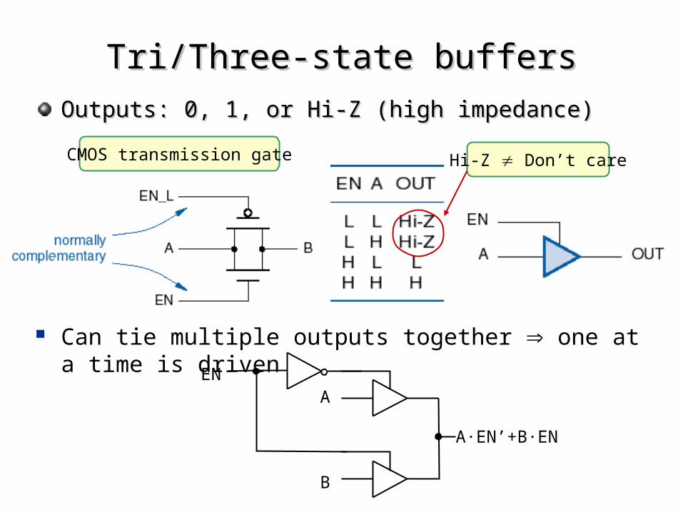
Outputs: 0, 1, or Hi-Z (high impedance)Outputs: 0, 1, or Hi-Z (high impedance)
Tri/Three-state buffersTri/Three-state buffers
Hi-Z Don’t careCMOS transmission gate
A
B
EN
A·EN’+B·EN
Can tie multiple outputs together one at a time is driven
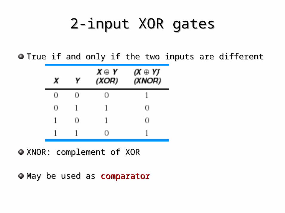
2-input XOR gates2-input XOR gates
True if and only if the two inputs are differentTrue if and only if the two inputs are different
XNOR: complement of XORXNOR: complement of XOR
May be used as May be used as comparatorcomparator
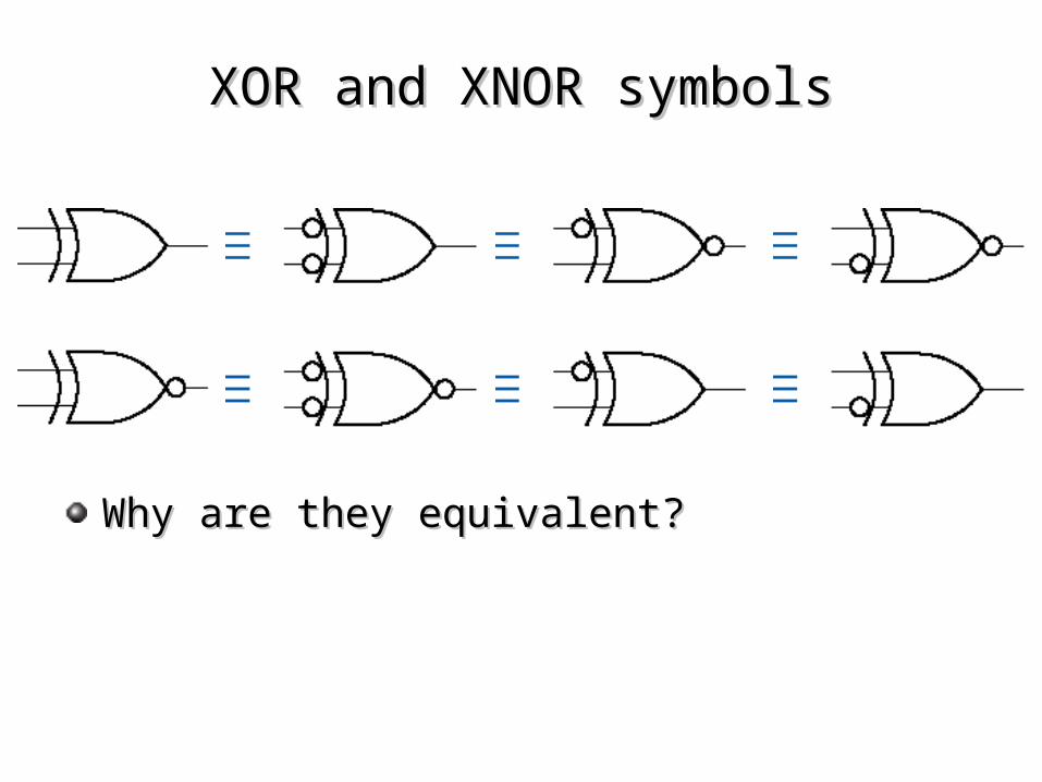
XOR and XNOR symbolsXOR and XNOR symbols
Why are they equivalent?Why are they equivalent?
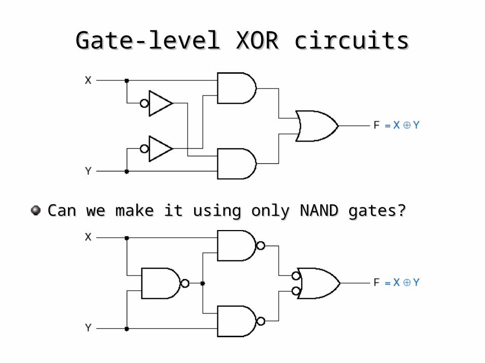
Gate-level XOR circuitsGate-level XOR circuits
Can we make it using only NAND gates?Can we make it using only NAND gates?
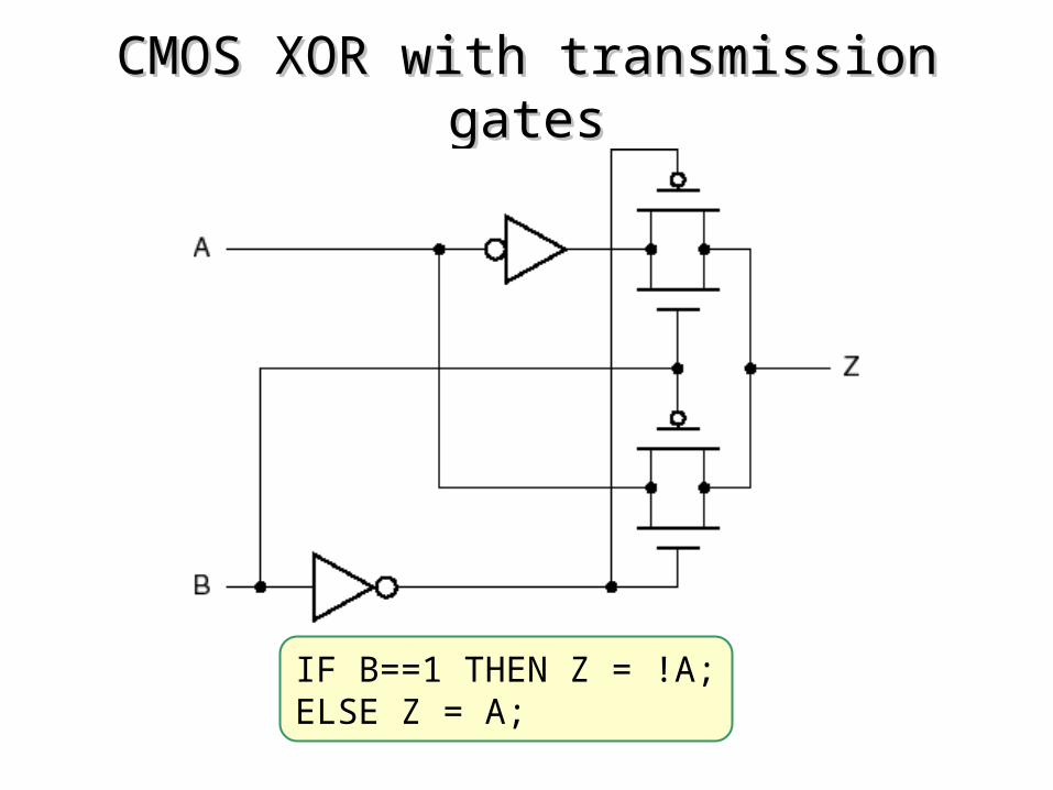
CMOS XOR with transmission gatesCMOS XOR with transmission gates
IF B==1 THEN Z = !A;ELSE Z = A;
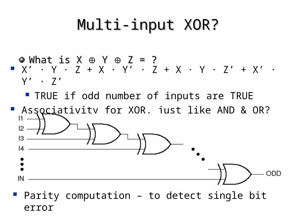
Multi-input XOR?Multi-input XOR?
What is X What is X Y Y Z = ? Z = ? X’ · Y · Z + X · Y’ · Z + X · Y · Z’ + X’ · Y’ · Z’
TRUE if odd number of inputs are TRUE Associativity for XOR, just like AND & OR?
Parity computation – to detect single bit error
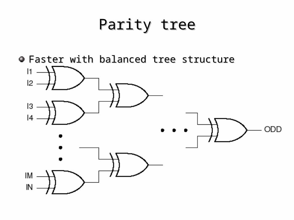
Parity treeParity tree
Faster with balanced tree structureFaster with balanced tree structure
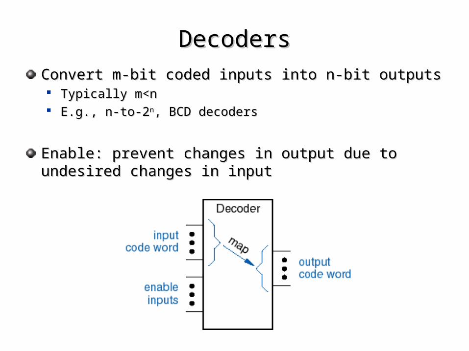
Convert m-bit coded inputs into n-bit outputsConvert m-bit coded inputs into n-bit outputs Typically m<nTypically m<n E.g., n-to-2E.g., n-to-2nn, BCD decoders, BCD decoders
Enable: prevent changes in output due to undesired Enable: prevent changes in output due to undesired changes in inputchanges in input
DecodersDecoders
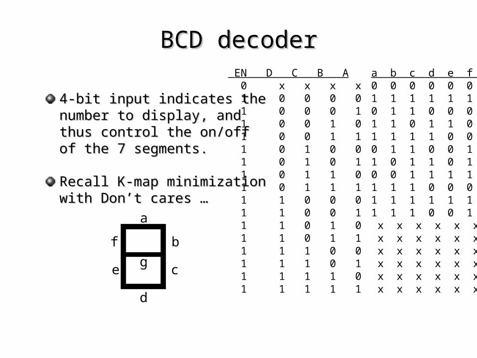
4-bit input indicates the 4-bit input indicates the number to display, and thus number to display, and thus control the on/off of the 7 control the on/off of the 7 segments.segments.
Recall K-map minimization with Recall K-map minimization with Don’t cares …Don’t cares …
EN D C B A a b c d e f g 0 x x x x 0 0 0 0 0 0 0 1 0 0 0 0 1 1 1 1 1 1 0 1 0 0 0 1 0 1 1 0 0 0 0 1 0 0 1 0 1 1 0 1 1 0 1 1 0 0 1 1 1 1 1 1 0 0 1 1 0 1 0 0 0 1 1 0 0 1 1 1 0 1 0 1 1 0 1 1 0 1 1 1 0 1 1 0 0 0 1 1 1 1 1 1 0 1 1 1 1 1 1 0 0 0 0 1 1 0 0 0 1 1 1 1 1 1 1 1 1 0 0 1 1 1 1 0 0 1 1 1 1 0 1 0 x x x x x x x 1 1 0 1 1 x x x x x x x 1 1 1 0 0 x x x x x x x 1 1 1 0 1 x x x x x x x 1 1 1 1 0 x x x x x x x 1 1 1 1 1 x x x x x x x
BCD decoderBCD decoder
a
b
c
d
e
f
g
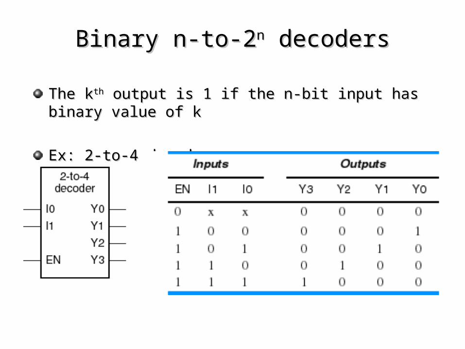
The kThe kthth output is 1 if the n-bit input has binary value of k output is 1 if the n-bit input has binary value of k
Ex: 2-to-4 decoderEx: 2-to-4 decoder
Binary n-to-2Binary n-to-2nn decoders decoders
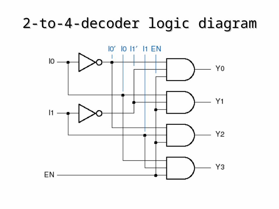
2-to-4-decoder logic diagram2-to-4-decoder logic diagram
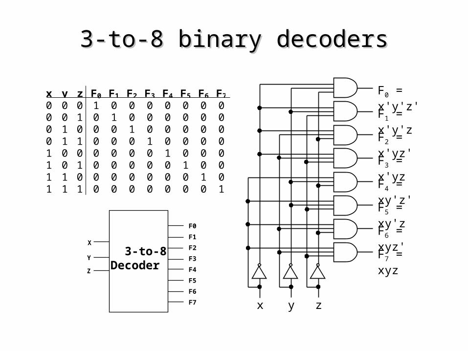
x y z F0 F1 F2 F3 F4 F5 F6 F7
0 0 0 1 0 0 0 0 0 0 00 0 1 0 1 0 0 0 0 0 00 1 0 0 0 1 0 0 0 0 00 1 1 0 0 0 1 0 0 0 01 0 0 0 0 0 0 1 0 0 01 0 1 0 0 0 0 0 1 0 01 1 0 0 0 0 0 0 0 1 01 1 1 0 0 0 0 0 0 0 1
F1 = x'y'z
x zy
F0 = x'y'z'
F2 = x'yz'
F3 = x'yz
F5 = xy'z
F4 = xy'z'
F6 = xyz'
F7 = xyz 3-to-8Decoder
X
Y
F0
F1
F2
F3
F4
F5
F6
F7
Z
3-to-8 binary decoders3-to-8 binary decoders
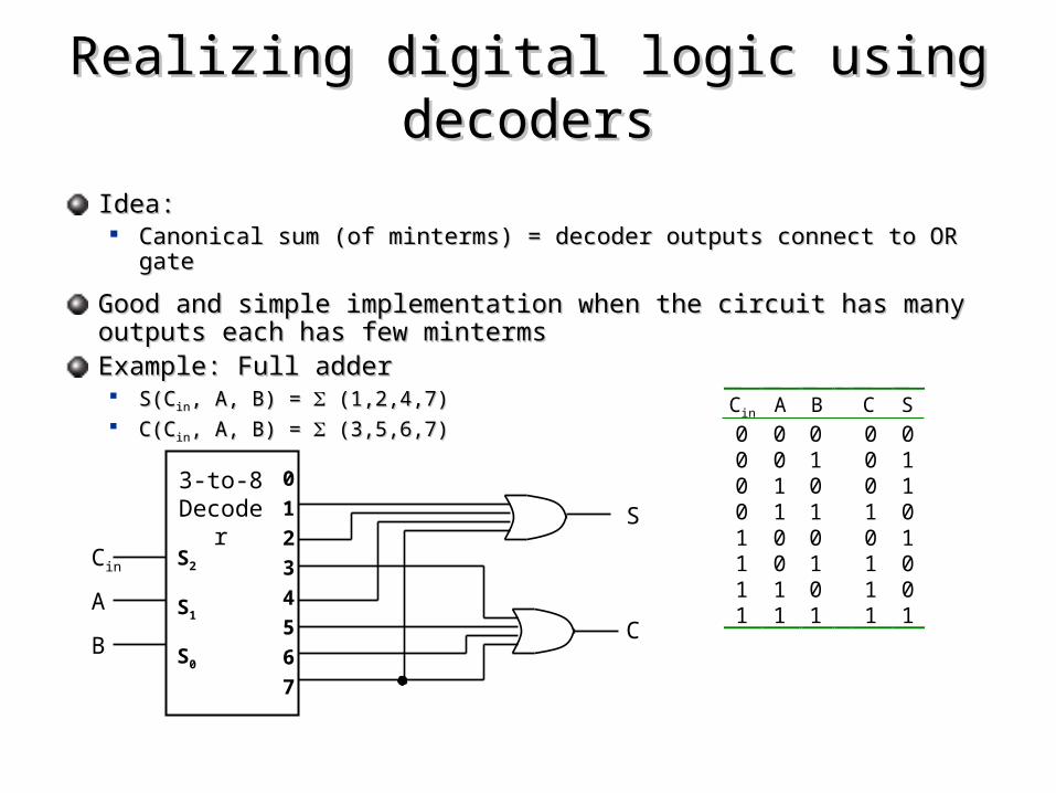
Idea:Idea: Canonical sum (of minterms) = decoder outputs connect to OR gateCanonical sum (of minterms) = decoder outputs connect to OR gate
Good and simple implementation when the circuit has many outputs Good and simple implementation when the circuit has many outputs each has few mintermseach has few mintermsExample: Full adderExample: Full adder
S(CS(Cinin, A, B) = , A, B) = (1,2,4,7) (1,2,4,7) C(CC(Cinin, A, B) = , A, B) = (3,5,6,7) (3,5,6,7)
Realizing digital logic using decodersRealizing digital logic using decoders
3-to-8Decoder
S2
S1
S0
Cin
A
B
0
1
2
3
4
5
6
7
S
C
Cin A B C S0 0 0 0 00 0 1 0 10 1 0 0 10 1 1 1 01 0 0 0 11 0 1 1 01 1 0 1 01 1 1 1 1
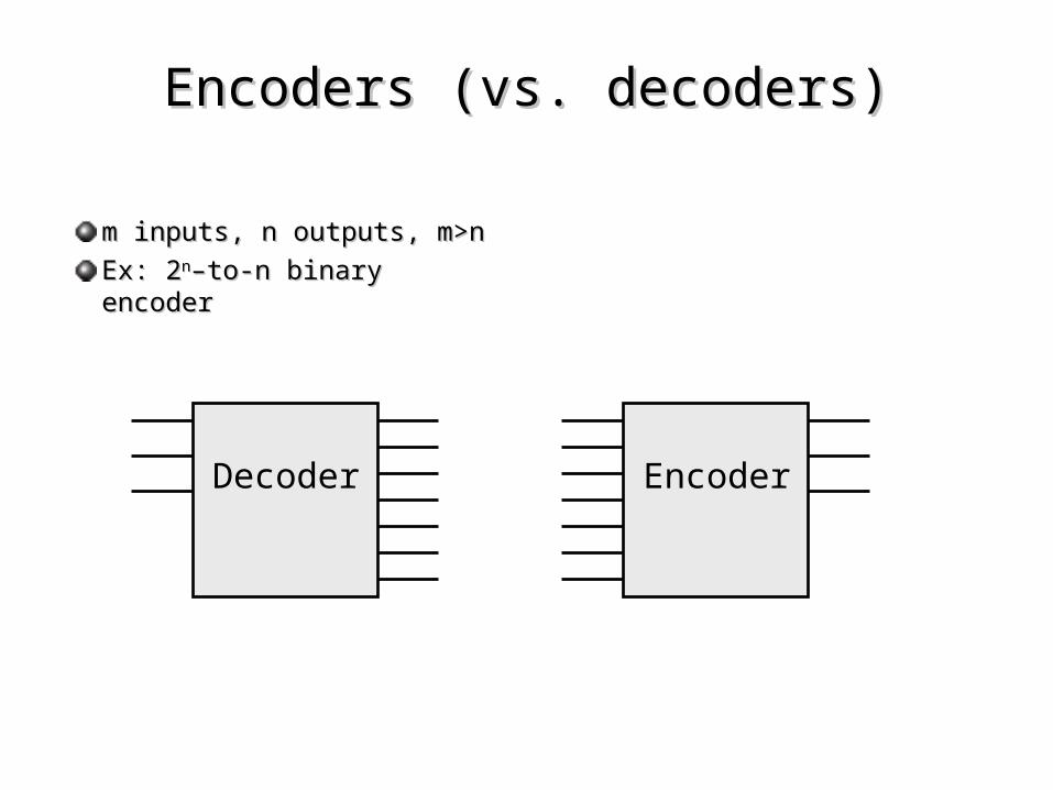
Encoders (vs. decoders)Encoders (vs. decoders)
m inputs, n outputs, m>nm inputs, n outputs, m>n
Ex: 2Ex: 2nn–to-n binary encoder–to-n binary encoder
Decoder Encoder
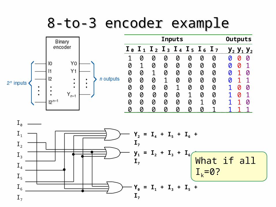
Inputs Outputs
I 0 I 1 I 2 I 3 I 4 I 5 I 6 I 7 y2 y1 y2
1 0 0 0 0 0 0 0 0 0 00 1 0 0 0 0 0 0 0 0 10 0 1 0 0 0 0 0 0 1 00 0 0 1 0 0 0 0 0 1 10 0 0 0 1 0 0 0 1 0 00 0 0 0 0 1 0 0 1 0 10 0 0 0 0 0 1 0 1 1 00 0 0 0 0 0 0 1 1 1 1
I0
I1
I2
I3
I4
I5
I6
I7
Y0 = I1 + I3 + I5 + I7
y1 = I2 + I3 + I6 + I7
Y2 = I4 + I5 + I6 + I7
8-to-3 encoder example8-to-3 encoder example
What if all Ik=0?
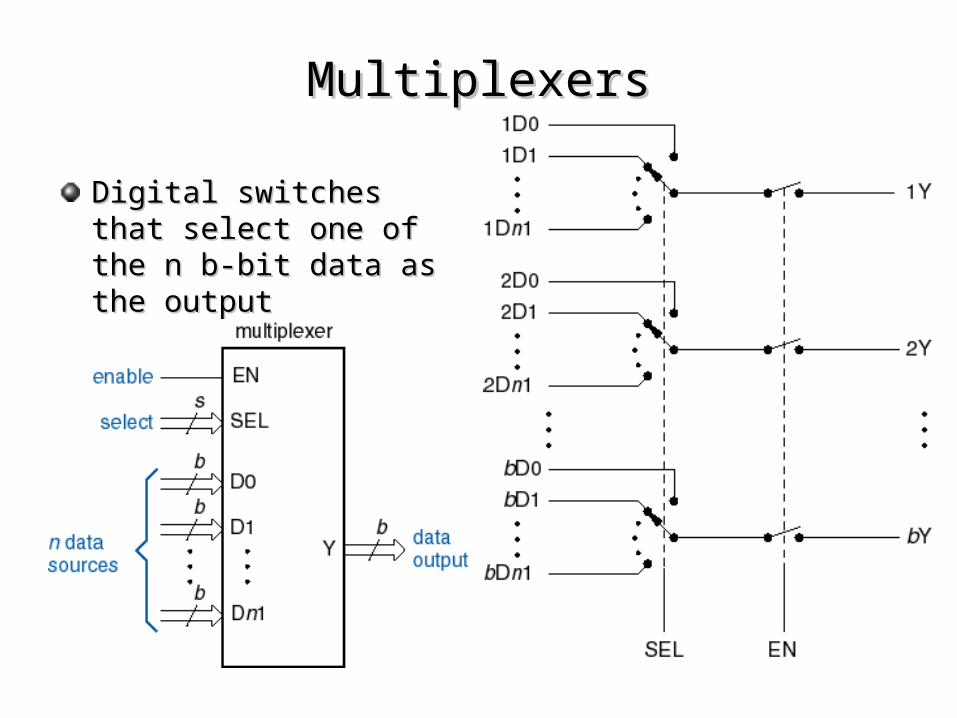
MultiplexersMultiplexers
Digital switches that select Digital switches that select one of the n b-bit data as one of the n b-bit data as the outputthe output
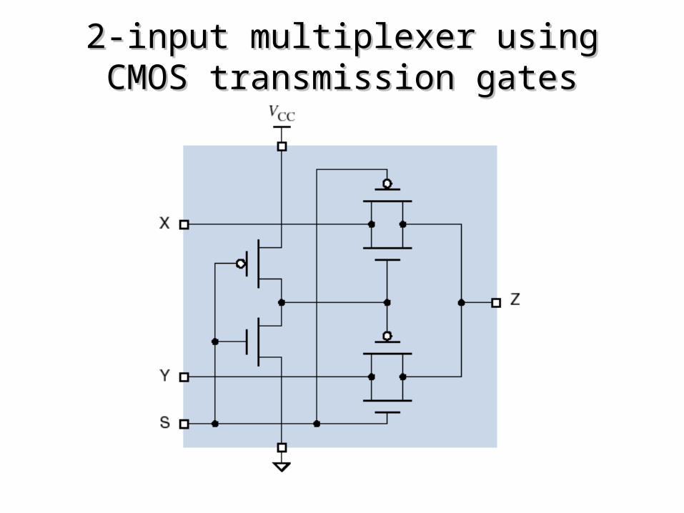
2-input multiplexer using CMOS 2-input multiplexer using CMOS transmission gatestransmission gates
mux Y
Inputs
select
S1 S0
I0
I1
I2
I3
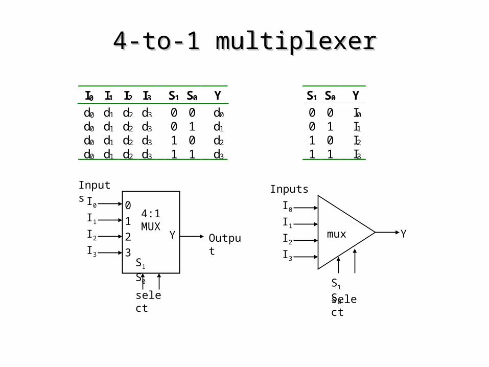
I0 I1 I2 I3 S1 S0 Y
d0 d1 d2 d3 0 0 d0
d0 d1 d2 d3 0 1 d1
d0 d1 d2 d3 1 0 d2
d0 d1 d2 d3 1 1 d3
S1 S0 Y
0 0 I0
0 1 I1
1 0 I2
1 1 I3
4:1MUX
Y
Inputs
select
S1 S0
I0
I1
I2
I3
0
1
2
3Output
4-to-1 multiplexer4-to-1 multiplexer
S1 S0
0 1 2 3
2-to-4 Decoder
I0
I1
I2
I3
Y
S1 S0
I0
I1
I2
I3
Y
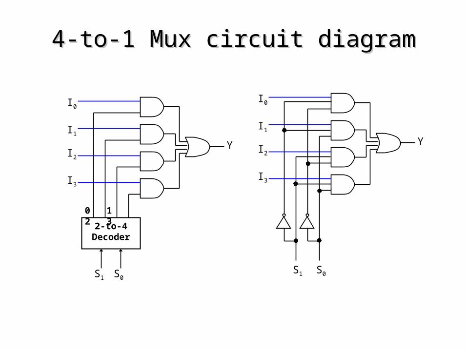
4-to-1 Mux circuit diagram4-to-1 Mux circuit diagram
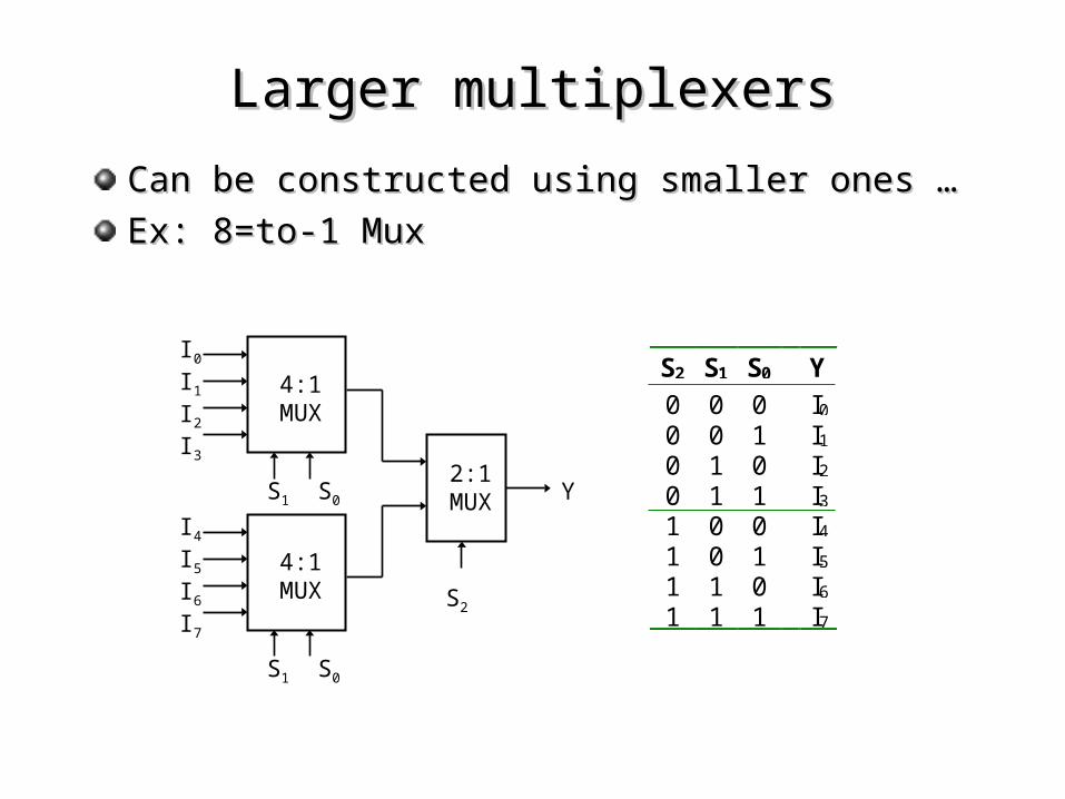
Can be constructed using smaller ones …Can be constructed using smaller ones …
Ex: 8=to-1 MuxEx: 8=to-1 Mux
4:1 MUX
I0
I1
I2
I3
S1 S0
4:1 MUX
I4
I5
I6
I7
S1 S0
2:1 MUX
S2
Y
S2 S1 S0 Y
0 0 0 I0
0 0 1 I1
0 1 0 I2
0 1 1 I3
1 0 0 I4
1 0 1 I5
1 1 0 I6
1 1 1 I7
Larger multiplexersLarger multiplexers
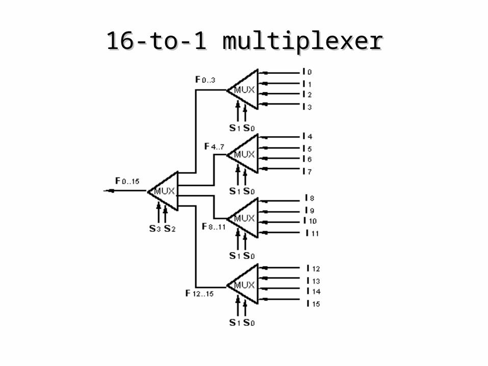
16-to-1 multiplexer16-to-1 multiplexer
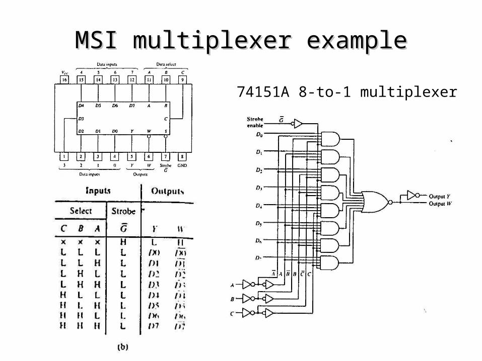
74151A 8-to-1 multiplexer
MSI multiplexer exampleMSI multiplexer example
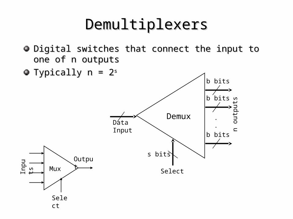
Digital switches that connect the input to one of n outputsDigital switches that connect the input to one of n outputs
Typically n = 2Typically n = 2ss
DemultiplexersDemultiplexers
s bits
Select
b bits
b bits
b bits
.
.DataInput
Demux
n o
utp
uts
Mux
Output
Inpu
ts
Select
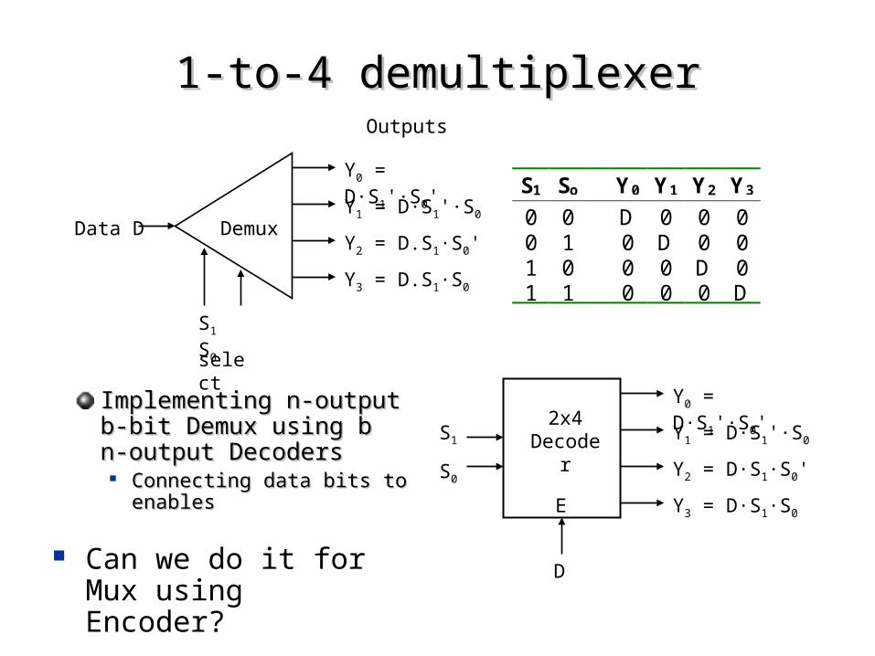
S1 So Y0 Y1 Y2 Y3
0 0 D 0 0 00 1 0 D 0 01 0 0 0 D 01 1 0 0 0 D
DemuxData D
Outputs
select
S1 S0
Y0 = D·S1'·S0'
Y1 = D·S1'·S0
Y2 = D.S1·S0'
Y3 = D.S1·S0
2x4 Decoder
D
S1
S0
Y0 = D·S1'·S0'
Y1 = D·S1'·S0
Y2 = D·S1·S0'
Y3 = D·S1·S0E
1-to-4 demultiplexer1-to-4 demultiplexer
Implementing n-output b-Implementing n-output b-bit Demux using b n-bit Demux using b n-output Decodersoutput Decoders
Connecting data bits to Connecting data bits to enablesenables
Can we do it for Mux using Encoder?
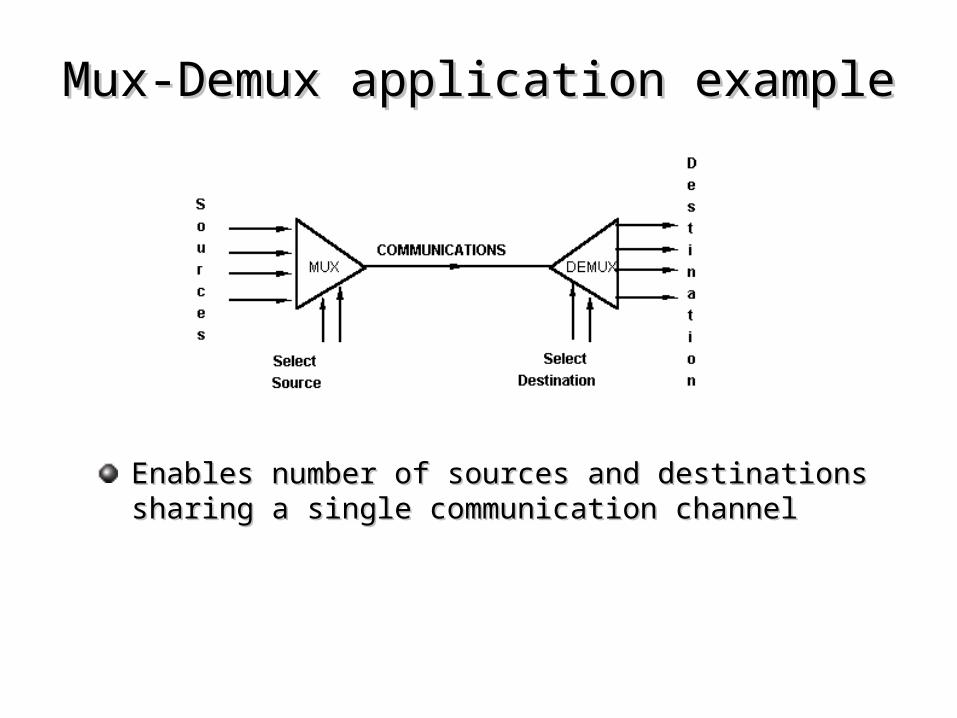
Mux-Demux application exampleMux-Demux application example
Enables number of sources and destinations sharing a Enables number of sources and destinations sharing a single communication channelsingle communication channel
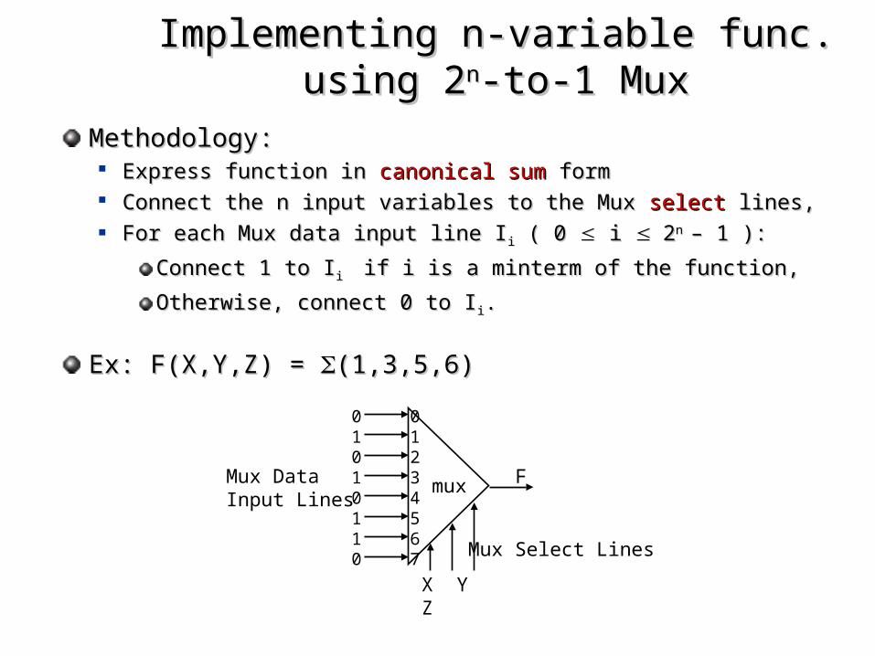
Implementing n-variable func. using 2Implementing n-variable func. using 2nn-to-1 -to-1 MuxMux
Methodology:Methodology: Express function in Express function in canonical sumcanonical sum form form Connect the n input variables to the Mux Connect the n input variables to the Mux selectselect lines, lines, For each Mux data input line IFor each Mux data input line I ii ( 0 ( 0 i i 22n n – 1 ):– 1 ):
Connect 1 to IConnect 1 to Ii i if i is a minterm of the function, if i is a minterm of the function,
Otherwise, connect 0 to IOtherwise, connect 0 to I ii..
Ex: Ex: F(X,Y,Z) = F(X,Y,Z) = (1,3,5,6)(1,3,5,6)
mux
X Y Z
01234567
01010110
F
Mux Select Lines
Mux DataInput Lines
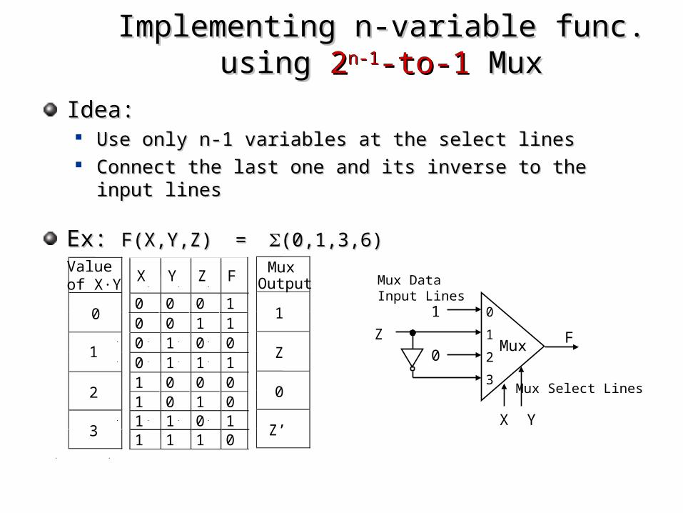
Idea:Idea: Use only n-1 variables at the select linesUse only n-1 variables at the select lines Connect the last one and its inverse to the input linesConnect the last one and its inverse to the input lines
Ex: Ex: F(X,Y,Z) = F(X,Y,Z) = (0,1,3,6) (0,1,3,6)
Implementing n-variable func. using Implementing n-variable func. using 22n-1n-1-to--to-11 Mux Mux
X Y Z F
0 0 0 10 0 1 10 1 0 00 1 1 11 0 0 01 0 1 01 1 0 11 1 1 0
MuxOutput
1
Z
0
Z’
Valueof X·Y
0
1
2
3
Mux
X Y
0
1
2
3
1
0 FZ
Mux Select Lines
Mux DataInput Lines

F(xF(x11,x,x22,x,x33,x,x44) = ) = (0,1,2,3,4,9,13,14,15) (0,1,2,3,4,9,13,14,15) using a 8-to-1 using a 8-to-1 Mux (Mux (74151A74151A) and an inverter.) and an inverter.
Another exampleAnother example

1.1. Express function F Express function F in in canonical sumcanonical sum form form
2.2. Choose n-1 variables connecting to mux Choose n-1 variables connecting to mux selectselect lines lines
3.3. Construct the Construct the truth tabletruth table via grouping inputs based via grouping inputs based on select line valueson select line values
4.4. Determine multiplexer input line i values by Determine multiplexer input line i values by comparing thecomparing the last input variable last input variable X and F: X and F: Four possible mux input line i values:Four possible mux input line i values:
0 if F=0 regardless of the value of X0 if F=0 regardless of the value of X
1 if F=1 regardless of the value of X1 if F=1 regardless of the value of X
F=XF=X
F=X’ F=X’
Implementing n-variable func. using Implementing n-variable func. using 22n-1n-1-to--to-11 Mux Mux